

Page 1

JULY 2003
SW625A-R3
SW626A-R3
Page 2

1
THE SERVSWITCH™ FAMILY
Welcome to the ServSwitch
TM
Family!
Thank you for purchasing a BLACK BOX®ServSwitch™Brand KVM switch! We
appreciate your business, and we think you’ll appreciate the many ways that your
new ServSwitch keyboard/video/mouse switch will save you money, time, and
effort.
That’s because our ServSwitch family is all about breaking away from the
traditional, expensive model of computer management. You know, the one-sizefits-all-even-if-it-doesn’t model that says, “One computer gets one user station, no
more, no less.” Why not a single user station (monitor, keyboard, and mouse) for
multiple computers—even computers of different platforms? Why not a pair of
user stations, each of which can control multiple computers? Why not multiple
user stations for the same computer?
With our ServSwitch products, there’s no reason why not. We carry a broad line
of robust solutions for all these applications. Do you have just two PCs, and need
an economical alternative to keeping two monitors, keyboards, and mice on your
desk? Or do you need to share dozens of computers, including a mix of IBM
®
PC,
RS/6000
®
, Apple®Macintosh®, Sun Microsystems®, and SGI®compatibles among
multiple users with different access levels? Does your switch have to sit solidly on a
worktable and use regular everyday cables? Or does it have to be mounted in an
equipment rack and use convenient many-to-one cables? No matter how large or
small your setup is, no matter how simple or how complex, we’re confident we
have a ServSwitch system that’s just right for you.
The ServSwitch
™
family from Black Box—the one-stop answer for all your KVM-
switching needs!
*
This manual will tell you all about your new Personal ServSwitch™ unit,
including how to install, operate, and troubleshoot it. For an introduction to the
Personal ServSwitch, see Chapter 2. The Personal ServSwitch product codes
covered in this manual are:
SW625A-R3
SW626A-R3
Page 3

2
PERSONAL SERVSWITCH™
TRADEMARKS USED IN THIS MANUAL
BLACK BOX and the logo are registered trademarks, and ServSwitch and
Personal ServSwitch are trademarks, of Black Box Corporation.
Apple and Macintosh are registered trademarks of Apple Computer, Inc.
IBM, PC/AT, PS/2, and RS/6000 are registered trademarks of International
Business Machines Corporation.
Microsoft, IntelliMouse, and Windows are registered trademarks and/or
trademarks of Microsoft Corporation in the United States and/or other
countries.
Sun Microsystems is a registered trademark of Sun Microsystems, Inc. in the
United States and other countries.
Any other trademarks mentioned in this manual are acknowledged to be the property of the
trademark owners.
Page 4

3
FCC/IC STATEMENTS
FEDERAL COMMUNICATIONS COMMISSION AND INDUSTRY CANADA
RADIO-FREQUENCY INTERFERENCE STATEMENTS
Class B Digital Device. This equipment has been tested and found to comply with
the limits for a Class B computing device pursuant to Part 15 of the FCC Rules.
These limits are designed to provide reasonable protection against harmful
interference in a residential installation. This equipment generates, uses, and can
radiate radio frequency energy and, if not installed and used in accordance with
the instructions, may cause harmful interference to radio communications.
However, there is no guarantee that interference will not occur in a particular
installation. If this equipment does cause harmful interference to radio or telephone
reception, which can be determined by turning the equipment off and on, the user
is encouraged to try to correct the interference by one of the following measures:
• Reorient or relocate the receiving antenna.
• Increase the separation between the equipment and receiver.
• Connect the equipment into an outlet on a circuit different from that to which
the receiver is connected.
• Consult an experienced radio/TV technician for help.
Caution: Changes or modifications not expressly approved by the party responsible
for compliance could void the user’s authority to operate the equipment.
To meet FCC requirements, shielded cables and power cords are required to
connect this device to a personal computer or other Class B certified device.
This digital apparatus does not exceed the Class B limits for radio noise emission from digital
apparatus set out in the Radio Interference Regulation of Industry Canada.
Le présent appareil numérique n’émet pas de bruits radioélectriques dépassant les limites
applicables aux appareils numériques de classe B prescrites dans le Règlement sur le brouillage
radioélectrique publié par Industrie Canada.
Page 5

4
PERSONAL SERVSWITCH™
NORMAS OFICIALES MEXICANAS (NOM)
ELECTRICAL SAFETY STATEMENT
INSTRUCCIONES DE SEGURIDAD
1. Todas las instrucciones de seguridad y operación deberán ser leídas antes de
que el aparato eléctrico sea operado.
2. Las instrucciones de seguridad y operación deberán ser guardadas para
referencia futura.
3. Todas las advertencias en el aparato eléctrico y en sus instrucciones de
operación deben ser respetadas.
4. Todas las instrucciones de operación y uso deben ser seguidas.
5. El aparato eléctrico no deberá ser usado cerca del agua—por ejemplo, cerca
de la tina de baño, lavabo, sótano mojado o cerca de una alberca, etc..
6. El aparato eléctrico debe ser usado únicamente con carritos o pedestales que
sean recomendados por el fabricante.
7. El aparato eléctrico debe ser montado a la pared o al techo sólo como sea
recomendado por el fabricante.
8. Servicio—El usuario no debe intentar dar servicio al equipo eléctrico más allá
a lo descrito en las instrucciones de operación. Todo otro servicio deberá ser
referido a personal de servicio calificado.
9. El aparato eléctrico debe ser situado de tal manera que su posición no
interfiera su uso. La colocación del aparato eléctrico sobre una cama, sofá,
alfombra o superficie similar puede bloquea la ventilación, no se debe colocar
en libreros o gabinetes que impidan el flujo de aire por los orificios de
ventilación.
10. El equipo eléctrico deber ser situado fuera del alcance de fuentes de calor
como radiadores, registros de calor, estufas u otros aparatos (incluyendo
amplificadores) que producen calor.
11. El aparato eléctrico deberá ser connectado a una fuente de poder sólo del
tipo descrito en el instructivo de operación, o como se indique en el aparato.
Page 6

5
NOM STATEMENT
12. Precaución debe ser tomada de tal manera que la tierra fisica y la polarización
del equipo no sea eliminada.
13. Los cables de la fuente de poder deben ser guiados de tal manera que no
sean pisados ni pellizcados por objetos colocados sobre o contra ellos,
poniendo particular atención a los contactos y receptáculos donde salen del
aparato.
14. El equipo eléctrico debe ser limpiado únicamente de acuerdo a las
recomendaciones del fabricante.
15. En caso de existir, una antena externa deberá ser localizada lejos de las lineas
de energia.
16. El cable de corriente deberá ser desconectado del cuando el equipo no sea
usado por un largo periodo de tiempo.
17. Cuidado debe ser tomado de tal manera que objectos liquidos no sean
derramados sobre la cubierta u orificios de ventilación.
18. Servicio por personal calificado deberá ser provisto cuando:
A: El cable de poder o el contacto ha sido dañado; u
B: Objectos han caído o líquido ha sido derramado dentro del aparato; o
C: El aparato ha sido expuesto a la lluvia; o
D: El aparato parece no operar normalmente o muestra un cambio en su
desempeño; o
E: El aparato ha sido tirado o su cubierta ha sido dañada.
Page 7

6
PERSONAL SERVSWITCH™
Contents
Chapter Page
1. Specifications ............................................................................................. 7
2. Introduction ............................................................................................... 9
3. Installation ................................................................................................ 10
3.1 Basic Installation ............................................................................... 10
3.1.1 Before You Install .................................................................... 10
3.1.2 Connecting Your Peripherals ................................................. 10
3.1.3 Connecting Your Computers ................................................. 11
3.2 Cascading .......................................................................................... 12
4. Operation ................................................................................................. 15
4.1 Selecting PCs ..................................................................................... 15
4.2 Scanning PCs ..................................................................................... 16
5. Troubleshooting ...................................................................................... 17
5.1 Problems That Might Occur ............................................................ 17
5.1.1 With the Unit Itself ................................................................. 17
5.1.2 With Video ............................................................................... 17
5.1.3 With the Mouse ....................................................................... 17
5.1.4 With the Keyboard .................................................................. 18
5.2 Calling Black Box .............................................................................. 19
5.3 Shipping and Packaging .................................................................... 19
Appendix: Keyboard Commands ................................................................... 20
Page 8

7
CHAPTER 1: Specifications
1. Specifications
Compliance — FCC Class B, IC Class/classe B
Hardware
Required — VGA/SVGA monitor that supports your computers’
highest video standard
Compliance — Safety: UL 1950, CSA 22.2 No. 950, EN60950;
EMI/RFI: FCC Class B, IC Class/classe B, EN55022,
EN50082
Standards — VGA (color or monochrome/page white), SVGA, or
XGA video
Interfaces — PS/2 keyboard and mouse, video as listed above, and
(computer side only) RS-232 serial mouse
Resolution — Up to 1024 x 768 noninterlaced at 80 Hz
Protocol — RS-232 (serial mouse): Asynchronous, 3-byte/8-bit
Data Rate — RS-232 (serial mouse): 1200 bps (fixed)
Maximum
Distance — 6 ft. (1.8 m) from Personal ServSwitch to any attached
device; might be farther depending on the quality of
your cable and the voltages at which your computers
drive the keyboard, mouse, and video signals
User Controls — Keyboard commands;
(1) Front-mounted CPU SELECT pushbutton
Indicators — SW625A-R3: (4) Front-mounted LEDs:
(2) CPU operating, (2) CPU selected;
SW626A-R3: (8) Front-mounted LEDs:
(4) CPU operating, (4) CPU selected
Connectors — All rear-mounted:
(1) 1.3-mm barrel jack for optional 6-VDC power;
(2) 6-pin mini-DIN female: (1) To shared keyboard,
(1) To shared mouse;
(1) HD15 female: To shared monitor;
Page 9

8
PERSONAL SERVSWITCH™
Connectors
(continued) — For each computer port (SW625A-R3 has 2, SW626A-R3
has 4):
(2) 6-pin mini-DIN female: (1) To keyboard ports,
(1) To PS/2 mouse ports;
(1) HD15 female: To video cards;
(1) DB9 female: To RS-232 serial mouse ports
Temperature
Tolerance — Operating: 41 to 104˚F (5 to 40˚C);
Storage: –4 to +122˚C (–20 to +50˚C)
Humidity
Tolerance — Up to 90% noncondensing
Enclosure — High-impact plastic
Power — From keyboard interface (no other power supply
necessary for most applications);
Optional external power supply for use in cascaded
systems (see Section 3.2):
For 115-VAC operation, PS626 (wallmount):
Input: 120 VAC, 60 Hz;
Output: 6 VDC, 700 mA;
For 220-VAC operation, PS626E (in-line):
Input: 100 to 250 VAC, 47 to 63 Hz autosensing;
Output: 6 VDC, 2 A
NOTE
In the unlikely event your computer interface does not
provide sufficient power to the Personal ServSwitch,
please use a Listed Direct Plug-In Transformer marked
“Class 2,” or a power supply that is confirmed to be a
Limited Power Source (“LPS”), and rated at 6 VDC, 700 mA
only.
Size — SW625A-R3
1.9" H (1U) x 8.1"W x 5"D (4.8 x 20.6 x 12.7 cm);
SW626A-R3 :
2.7" H (1U) x 8.1"W x 5"D (6.9 x 20.6 x 12.7 cm)
Weight — SW625A-R3:
Net: 1.1 lb. (0.5 kg); Shipping: 1.5 lb. (0.7 kg);
SW626A-R3:
Net: 1.3 lb. (0.6 kg); Shipping: 1.7 lb. (0.8 kg)
Page 10

9
CHAPTER 2: Introduction
2. Introduction
The Personal ServSwitch allows you to control multiple PCs, easily and affordably,
with just one keyboard, monitor and mouse. There is no software to install and no
boards to configure, so installation is simple. The Switch works with IBM
®
PC/AT
®
and PS/2®compatible systems that support VGA, SVGA, or XGA video.
When you turn on your PCs, they will boot up without interruption, because the
Personal ServSwitch sends out keyboard-response signals that eliminate boot-time
keyboard errors. You can turn on your PCs one at a time or all at once. The first
available channel is automatically selected upon power-up.
You can switch computer channels two ways: with the CPU Select button on the
Personal ServSwitch’s front panel, or with a short keyboard sequence.
The Personal ServSwitch also has these features:
• PS/2 mouse translation: Your PS/2 mouse will work with any attached PC,
regardless of whether the PC uses a serial or PS/2 mouse!
• Full support for the Microsoft
®
IntelliMouse®.
• You can use standard straight-through-pinned keyboard, mouse, and video
cables to attach computers to the Switch.
• Built-in scanning: Scan through all of your attached PCs automatically, for 2 to
60 seconds each.
• Cascadable expansion: Add up to two additional tiers of Personal ServSwitch
units for system expansion. With cascading, the SW625A-R3 supports up to
8 PCs; the SW626A-R3 supports up to 64 attached computers.
• Hot-pluggable: New PCs can be added or removed without powering down the
Switch or other attached PCs.
•
Status LEDs: Two LEDs per port give you constant readings on the status of your
Personal ServSwitch. The green LED stays lit as long as a powered PC is attached
to the port; the amber LED lights to show that the port is selected for display.
Page 11

10
PERSONAL SERVSWITCH™
3. Installation
3.1 Basic Installation
3.1.1 B
EFOREYOU
I
NSTALL
You will need the appropriate kits of straight-through-pinned cables in order to
connect your PCs to the Personal ServSwitch, one kit for each PC. These kits
consist of 6-pin mini-DIN male-to-male cables for keyboard connections, HD15
male-to-male for video connections, and either a second 6-pin mini-DIN male-tomale for PS/2 type mouse connections (our product code EHN405-PS2) or a DB9
male-to-female for serial mouse connections (our product code EHN405-AT). The
EHN405-AT kit also comes with an FA212 keyboard adapter so that you can
connect a computer with one of the older-style 5-pin DIN AT keyboard connectors.
3.1.2 C
ONNECTINGYOURPERIPHERALS
Take these steps to attach the shared peripherals to your Personal ServSwitch,
referring to Figure 3-1. Use their own cables to connect your VGA monitor,
keyboard, and mouse to the Switch instead of your computer: Plug your PS/2
keyboard’s cable into the 6-pin mini-DIN Switch connector marked with the
keyboard symbol (“ ”; this connector is on the back of your Switch in its User
Console section). Plug your PS/2’s mouse cable into the 6-pin mini-DIN User
Console connector marked with the mouse symbol (“ ”). Lastly, plug your VGA,
SVGA, or XGA video cable into the HD15 female User Console video port.
Figure 3-1. Attaching the peripherals.
Your PS/2
keyboard cable
Your PS/2
mouse cable
Your VGA/
SVGA/XGA
video cable
6V
0
CONSOLE
D
6VDC
0.7A
SOLE
D
Page 12

11
CHAPTER 3: Installation
3.1.3 C
ONNECTINGYOURCOMPUTERS
Take these steps to attach the computers to your Personal ServSwitch, referring to
Figure 3-2:
Figure 3-2. Attaching the computers.
1.
Power down all computers that will be part of your Personal ServSwitch system.
2. Get the appropriate cable kit to attach your first computer to the Switch
(refer to Section 3.1.1). Plug the keyboard patch cable (6-pin mini-DIN maleto-male) into the connector of the first available computer port on your
Personal ServSwitch. The computer ports are labeled A and B on the
SW625A-R3 and A through D on the SW626A-R3.
Next, plug your mouse patch cable into the appropriate connector of the
same port. Depending on what type of mouse port your computer has, you
should either plug the second 6-pin mini-DlN male-to-male cable from an
EHN405-PS2 kit into the 6-pin mini-DIN female (PS/2 style) connector, or
plug the DB9 male-to-female cable from the EHN405-AT kit into the DB9
female (PC/AT style) connector. Attach only one mouse cable per computer.
Plug the HD15 male-to-male video cable into the monitor input connector.
C
PS/2
Keyboard
Cable
Mouse
Cable
VGA Video
Cable
VDC
.7A
USER CONSOLE
D
C
Page 13

12
PERSONAL SERVSWITCH™
Lastly, plug the free end of each cable into the matching port on your
computer. (You’ll need the FA212 keyboard adapter from the EHN405-AT
cable kit for any computer that has a 5-pin DIN keyboard port.) Tighten all
thumbscrews.
3. Repeat step 2 for each additional computer you want to attach to the Switch,
then power up all attached computers.
3.2 Cascading
If you need to control more computers than one Personal ServSwitch will support,
you can cascade, or interconnect, multiple Personal ServSwitch units.
You can connect your keyboard, monitor, and PS/2 mouse to the User Console
connectors of the first Personal ServSwitch in the cascade, called the “base unit,”
just as you would for a single unit installation. Additional Switches, called
“expansion units,” can be added to the system by connecting cables between the
labeled ports on the base unit and the User Console connectors of the expansion
unit. (Ports are labeled A and B on the SW625A-R3, A through D on the
SW626A-R3.) See Figure 3-3.
Figure 3-3. Cascade: Base unit (bottom) plus one tier with one expansion
unit (top).
Cables from
EHN405-PS2
cable kit
Base unit
Expansion unit
6V
0
NSOLE
USER CONSOLE
D
C
B
D
C
A
6VDC
0.7A
Page 14
13
CHAPTER 3: Installation
At this point, you can either connect PCs to the ports on the expansion units, or
expand your system further by adding a second tier of expansion units, as shown in
Figure 3-4. (The maximum size of a cascaded system is one SW626A-R3 base unit,
four first-tier SW626A-R3 expansion units, sixteen second-tier SW626A-R3
expansion units,
and 64 PCs.)
Figure 3-4. Cascade: Base unit (bottom) plus two tiers, each with one
expansion unit (middle, top).
Before beginning your cascaded installation, please note that you will need an
EHN405-PS2 cable kit for each expansion unit in the system.
1.
Choose an unused computer port on the rear of your Personal ServSwitch base unit.
Plug one of the kit’s 6-pin mini-DIN male-to-male cables into the port’s
connector, and the other 6-pin mini-DIN male-to-male cable into the PS/2
style (6-pin mini-DIN) connector. Plug the kit’s HD15 male-to-male video
cable into the port’s HD15 female video connector.
2. Plug the other end of the PS/2 keyboard cable into the User Console
connector on your Personal ServSwitch expansion unit. Plug the other end of
the PS/2 mouse cable connector into the User Console connector. Plug
the other end of the video cable into the User Console video connector. See
Figure 3-5 on the next page.
Cables from
EHN405-PS2
cable kit
Base unit
Expansion unit
Expansion unit
6V
0
N
S
O
LE
6V
0
6VD
0.7A
D
C
N
SO
LE
D
C
U
SER
C
O
NS
O
LE
D
B
A
C
Page 15

14
PERSONAL SERVSWITCH™
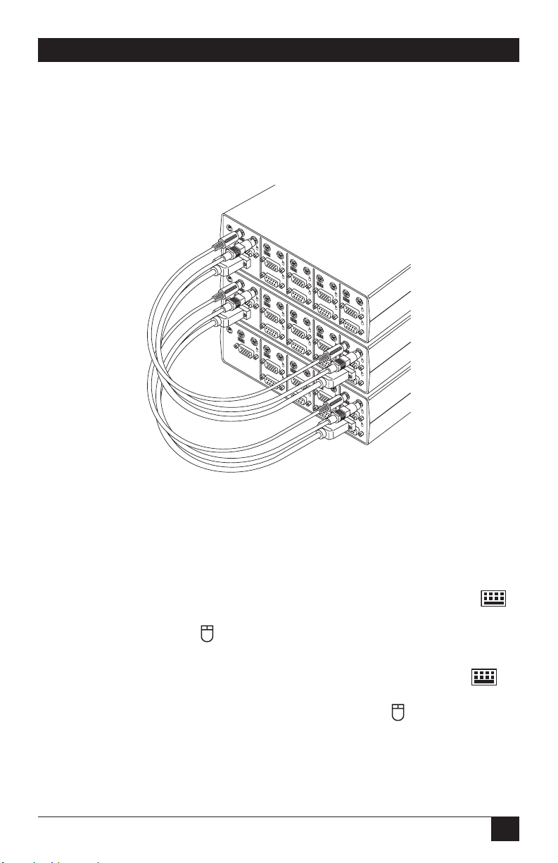
Figure 3-5. Cascade: Cable interconnection.
3.
For cascaded operation, you should use the optional 6-VDC power supply—
our
product code PS626 for 110-VAC operation or PS626E for 220-VAC
operation—with any Switch that does not have at least one attached PC. (You
should not need this power supply with any Switch that can get power from an
attached PC.) Plug the transformer into the power socket on the Switch’s rear
panel, as shown in Figure 3-6. Plug the other end into an appropriate AC wall
outlet. In the unlikely event your computer interface does not provide
sufficient power to the Personal ServSwitch, please use a Listed Direct Plug-In
Transformer marked “Class 2,” or a power supply that is confirmed to be a
Limited Power Source (“LPS”), and rated at 6 VDC, 700 mA only.
Figure 3-6. Cascade: Attaching the optional 6-VDC power supply.
4. Make sure that all Switch units with power supplies are plugged in, then turn
on all attached PCs.
6V
0
NSOLE
6VDC
0.7A
USER
D
DC
0.7A
USER CONSOLE
D
Page 16

15
CHAPTER 4: Operation
4. Operation
You can turn on your PCs one at a time or all at once. The green LEDs over each
port letter on the Personal ServSwitch will light, indicating that the attached
computer is powered on. After power-up, the Switch will light the amber LED of
the currently selected port. Other PCs may now be selected for operation, as
detailed in Section 4.1. You can also scan the PCs, as shown in Section 4.2, or enter
other commands (see the Appendix).
4.1 Selecting PCs
There are two ways to select a PC on the Personal ServSwitch. One way is with the
CPU
Select pushbutton. Pressing this selects the next computer in sequence; for
example, if you are currently interacting with the PC on Port B, pressing CPU Select
switches to the PC on Port C. The other way of selecting ports is by entering a short
sequence of keystrokes on the keyboard. This is called keyboard, or hotkey, switching.
Press the Control key twice within one second to place your Personal ServSwitch
in Command Mode. Your keyboard LEDs (Num Lock, Caps Lock, and Scroll Lock)
will flash to verify that you are operating in Command Mode. Now, whatever you
type will be interpreted as Personal ServSwitch system commands until you press
[Enter] to accept the command or [Esc] (escape) to cancel.
Once you’re in Command Mode, type the letter(s) corresponding to the port
address of the PC you wish to select. (The port address will be one letter if you are
using a single Switch, two letters if you’re using two tiers of Switches, and so on,
because you need to specify which port each successive expansion unit is on before
you specify the actual PC port.) For example:
[CTRL][CTRL] C [ENTER] Selects the PC on Port C.
[CTRL][CTRL] B [ENTER] Selects the PC on Port B.
[CTRL][CTRL] AB [ENTER] Selects the expansion unit on the base unit’s
Port A, then the PC on the expansion unit’s
Port B.
[CTRL][CTRL] D [ESCAPE] (When [ESCAPE] is pressed, command in
progress is aborted. Currently selected port
remains selected.)
Page 17

16
PERSONAL SERVSWITCH™
4.2 Scanning PCs
The Personal ServSwitch’s scanning feature allows you to automatically monitor, or
scan, each PC in your Switch system. If you use the keyboard during scanning, the
scan will pause until you finish, then resume with the next PC. (You can set the
Switch to pause scanning on mouse activity as well if you want.) The scan “dwell
time” (the length of time each PC’s video remains on the screen) can be changed
at any time. Scanning will be halted if the Halt command is entered or if another
PC is selected.
The following key sequences configure and control scanning.
Key Sequence Action
[CTRL][CTRL] Dnn [ENTER] Sets the dwell time in seconds, where nn = any
value from 02 to 60. The default value is 05
(five seconds).
[CTRL][CTRL] SG [ENTER] Scan Go (starts scan).
[CTRL][CTRL] SH [ENTER] Scan Halt (stops scan).
[CTRL][CTRL] M- [ENTER] Mouse activity does not pause scan (default
setting).
[CTRL][CTRL] M+ [ENTER] Mouse activity pauses scan in the same way that
keyboard activity does.
Some examples:
[CTRL][CTRL] D10 [ENTER] Each PC’s video will remain on screen for ten
seconds before the next port is displayed.
[CTRL][CTRL] SG [ENTER] Scanning begins with the current computer,
then continues to the next PC in sequence.
[CTRL][CTRL] SH [ENTER]
Scanning stops until the Go command is reissued.
[CTRL][CTRL] M+ [ENTER] Until the M- command is issued, scans pause on
ports until all keyboard and mouse activity
stops.
Page 18

17
CHAPTER 5: Troubleshooting
5. Troubleshooting
5.1 Problems That Might Occur
5.1.1 W
ITH THEUNITITSELF
Green channel LED not lit
Verify that the computer is powered on. Check the cabling between your computer
and the Personal ServSwitch. Verify that a keyboard works when plugged directly
into your PC.
Unable to switch channels
Verify that all attached PCs are powered and correctly connected to the unit.
5.1.2 W
ITHVIDEO
No video
Verify that the video cable between the computer and the Personal ServSwitch is
connected to the selected port. Verify that the monitor cable is also correctly
connected to the video port in the User Console section of the single or base unit.
Power down the computer. Connect the monitor directly to the computer and
power up again. If the monitor does not operate correctly when attached directly
to the computer, try another monitor.
5.1.3 W
ITH THEMOUSE
Mouse jumps or “hugs screen”
Try the mouse-resynchronization command, [CTRL][CTRL] ZM [ENTER], once
or—if the first command doesn’t help—twice.
If this doesn’t work—especially if the mouse has been hot-plugged while the
selected PC is running in Windows®—you might need to exit Windows and restart it.
Mouse is inoperable on one or more channels
Try the mouse reset command: [CTRL][CTRL] MR [ENTER] if it’s a PS/2 mouse
or [CTRL][CTRL] MW [ENTER] if it’s an IntelliMouse.
Verify that the cables from the computer to the Personal ServSwitch are
connected properly. Verify that the mouse is plugged into the mouse port in the
User Console section on the rear panel of the single or base unit.
Verify that the computer works properly with a mouse connected directly to it. If
not, try another mouse.
Lost mouse signal after hot-plugging cascaded Switch
This sometimes happens. Switch ports on the cascaded Switch to restore the signal.
Page 19

18
PERSONAL SERVSWITCH™
5.1.4 W
ITH THEKEYBOARD
Keyboard is inoperable on one or more channels
Verify that the cables from the PC to the Personal ServSwitch are connected
properly. Verify that the keyboard is plugged into the keyboard port in the User
Console section on the rear panel of the single or base unit.
Verify that the keyboard works properly when connected directly to the
computer. If not, try a different keyboard.
If the keyboard still does not function, cycle power on all attached computers
and try again.
Keyboard is inoperable after switching channels or
Characters on screen do not match keyboard input
Some types of IBM compatible computers, particularly some PS/2s and high-end
servers, use unusual keyboard “scan modes.” This means that they interpret
keyboard signals slightly differently than most other computers. Try changing the
keyboard scan mode by using the keyboard command sequence [CTRL][CTRL]
Kn [ENTER], where n is the number of the scan mode from 1 to 3 (2 is the default
used by most IBM compatible computers).
Page 20

19
CHAPTER 5: Troubleshooting
5.2 Calling Black Box
If you determine that your Personal ServSwitch is malfunctioning, do not attempt to
alter or repair the unit. It contains no user-serviceable parts. Contact Black Box
Technical Support at 724-746-5500.
Before you do, make a record of the history of the problem. We will be able to
provide more efficient and accurate assistance if you have a complete description,
including:
• the nature and duration of the problem;
• when the problem occurs;
• the components involved in the problem—that is, what type of PCs, what type
of keyboard, brand of mouse, make and model of monitor, etc.;
• any particular application that, when used, appears to create the problem or
make it worse; and
• the results of any testing you’ve already done.
5.3 Shipping and Packaging
If you need to transport or ship your Personal ServSwitch:
• Package it carefully. We recommend that you use the original container.
• Before you ship the unit back to Black Box for repair or return, contact us to
get a Return Authorization (RA) number.
Page 21

20
PERSONAL SERVSWITCH™
Appendix: Keyboard Commands
These are all of the keyboard commands that you can currently use to operate the
Personal ServSwitch.
Key Sequence Action
[CTRL][CTRL] X [ENTER]
Selects the PC on the single or base unit’s port X.
[CTRL][CTRL] XY [ENTER] Selects the expansion unit on the base unit’s
port X and the PC on that expansion unit’s port Y.
[CTRL][CTRL] XYZ [ENTER] Selects the expansion unit on the base unit’s
port X, the expansion unit on that unit’s port Y,
and the PC on that unit’s port Z.
[CTRL][CTRL] Dnn [ENTER] Sets the dwell time in seconds, where nn = any
value from 02 to 60. Default is 05 (five seconds).
[CTRL][CTRL] SG [ENTER] Scan Go (starts scan).
[CTRL][CTRL] SH [ENTER] Scan Halt (stops scan).
[CTRL][CTRL] M- [ENTER] Mouse activity does not pause scan (default).
[CTRL][CTRL] M+ [ENTER] Mouse activity pauses scan.
[CTRL][CTRL] ZM [ENTER] Resynchronizes the mouse.
[CTRL][CTRL] MR [ENTER] Resets the mouse if it is PS/2 type.
[CTRL][CTRL] MW [ENTER] Resets the mouse if it is an IntelliMouse.
[CTRL][CTRL] Kn [ENTER] Sets the keyboard scan mode, where n = the
number of the scan mode from 1 to 3. Default
is scan mode 2.
[CTRL][CTRL] AV [ENTER] Displays the current firmware version of your
Switch. You must be either at a DOS prompt or
in a text editor or word processor to view this.
Page 22

NOTES
Page 23

NOTES
Page 24

Doc. No. 590-033-001E
Customer Support Information:
FREE tech support 24 hours a day, 7 days a week: Call 724-746-5500 or fax 724-746-0746.
Mailing address: Black Box Corporation, 1000 Park Dr., Lawrence, PA 15055-1018
World-Wide Web: www.blackbox.com • E-mail: info@blackbox.com
© Copyright 2003. Black Box Corporation. All rights reserved.
 Loading...