

Page 1

CUSTOMER
SUPPORT
INFORMATION
Order toll-free in the U.S. 24 hours, 7 A.M. Monday to midnight Friday: 877-877-BBOX
FREE technical support, 24 hours a day, 7 days a week: Call 724-746-5500 or fax 724-746-0746
Mail order: Black Box Corporation, 1000 Park Drive, Lawrence, PA 15055-1018
Web site: www.blackbox.com • E-mail: info@blackbox.com
OCTOBER 1996
SW545A
SW546A
Port Manager Switches
Port Manager Switch
ON
RDY
ACTIVITY
1
2
3
4
5
6
7
8
Port Manager Switch
ON
RDY
ACTIVITY
1
2
3
4
5
6
7
8
ACTIVITY
1
2
3
4
5
6
7
8
Page 2

FCC AND IC STATEMENTS, TRADEMARKS
3
FEDERAL COMMUNICATIONS COMMISSION
AND
INDUSTRY CANADA
RADIO FREQUENCY INTERFERENCE STATEMENTS
This equipment generates, uses, and can radiate radio frequency
energy and if not installed and used properly, that is, in strict
accordance with the manufacturer’s instructions, may cause
interference to radio communication. It has been tested and found
to comply with the limits for a Class A computing device in
accordance with the specifications in Subpart J of Part 15 of FCC
rules, which are designed to provide reasonable protection against
such interference when the equipment is operated in a commercial
environment. Operation of this equipment in a residential area is
likely to cause interference, in which case the user at his own
expense will be required to take whatever measures may be
necessary to correct the interference.
Changes or modifications not expressly approved by the party
responsible for compliance could void the user’s authority to
operate the equipment.
This digital apparatus does not exceed the Class A limits for radio noise
emission from digital apparatus set out in the Radio Interference
Regulation of Industry Canada.
Le présent appareil numérique n’émet pas de bruits radioélectriques
dépassant les limites applicables aux appareils numériques de
classe A prescrites dans le Règlement sur le brouillage radioélectrique
publié par Industrie Canada.
TRADEMARKS USED IN THIS MANUAL
AT and IBM are registered trademarks, and PC/XT is a trademark,
of IBM Corporation.
ProComm is a registered trademark of Symantec Corporation.
Page 3

PORT MANAGER SWITCHES
NORMAS OFICIALES MEXICANAS (NOM) ELECTRICAL SAFETY STATEMENT
INSTRUCCIONES DE SEGURIDAD
1. Todas las instrucciones de seguridad y operación deberán ser leídas antes
de que el aparato eléctrico sea operado.
2. Las instrucciones de seguridad y operación deberán ser guardadas para
referencia futura.
3. Todas las advertencias en el aparato eléctrico y en sus instrucciones de
operación deben ser respetadas.
4. Todas las instrucciones de operación y uso deben ser seguidas.
5. El aparato eléctrico no deberá ser usado cerca del agua—por ejemplo,
cerca de la tina de baño, lavabo, sótano mojado o cerca de una alberca,
etc.
6. El aparato eléctrico debe ser usado únicamente con carritos o pedestales
que sean recomendados por el fabricante.
7. El aparato eléctrico debe ser montado a la pared o al techo sólo como
sea recomendado por el fabricante.
8. Servicio—El usuario no debe intentar dar servicio al equipo eléctrico más
allá a lo descrito en las instrucciones de operación. Todo otro servicio
deberá ser referido a personal de servicio calificado.
9. El aparato eléctrico debe ser situado de tal manera que su posición no
interfiera su uso. La colocación del aparato eléctrico sobre una cama,
sofá, alfombra o superficie similar puede bloquea la ventilación, no se
debe colocar en libreros o gabinetes que impidan el flujo de aire por los
orificios de ventilación.
10. El equipo eléctrico deber ser situado fuera del alcance de fuentes de
calor como radiadores, registros de calor, estufas u otros aparatos
(incluyendo amplificadores) que producen calor.
11. El aparato eléctrico deberá ser connectado a una fuente de poder sólo
del tipo descrito en el instructivo de operación, o como se indique en el
aparato.
4
Page 4

NOM STATEMENT
12. Precaución debe ser tomada de tal manera que la tierra fisica y la
polarización del equipo no sea eliminada.
13. Los cables de la fuente de poder deben ser guiados de tal manera que no
sean pisados ni pellizcados por objetos colocados sobre o contra ellos,
poniendo particular atención a los contactos y receptáculos donde salen
del aparato.
14. El equipo eléctrico debe ser limpiado únicamente de acuerdo a las
recomendaciones del fabricante.
15. En caso de existir, una antena externa deberá ser localizada lejos de las
lineas de energia.
16. El cable de corriente deberá ser desconectado del cuando el equipo no
sea usado por un largo periodo de tiempo.
17. Cuidado debe ser tomado de tal manera que objectos liquidos no sean
derramados sobre la cubierta u orificios de ventilación.
18. Servicio por personal calificado deberá ser provisto cuando:
A: El cable de poder o el contacto ha sido dañado; u
B: Objectos han caído o líquido ha sido derramado dentro del
aparato; o
C: El aparato ha sido expuesto a la lluvia; o
D: El aparato parece no operar normalmente o muestra un cambio en
su desempeño; o
E: El aparato ha sido tirado o su cubierta ha sido dañada.
5
Page 5

PORT MANAGER SWITCHES
Contents
Chapter Page
1. Specifications ............................................................................................. 7
2. Introduction ............................................................................................. 11
2.1 General Overview .............................................................................. 11
2.2 The Port Manager Switches Illustrated ........................................... 13
3. Getting Started ......................................................................................... 15
3.1 Setting Default Communication Parameters .................................. 15
3.2 Connecting Your PC to the PM Switch ............................................ 16
3.3 Applying Power to the PM Switch .................................................... 17
3.4 Communicating with the PM Switch Unit ....................................... 18
4. Installation ................................................................................................ 22
4.1 Setting the SETUP Switch ................................................................ 22
4.2 Connecting a Modem to the PM Switch .......................................... 25
4.3 Initializing the Unit to Default Settings .......................................... 26
4.4 Connecting Devices to the PM Switch ............................................. 26
5. Configuration ........................................................................................... 28
5.1 Accessing the PM Switch’s Command Mode .................................. 28
5.2 Defining and Reading the Site I.D. ................................................... 29
5.3 Port Configuration ............................................................................ 30
6. Operation ................................................................................................. 36
6.1 Connecting and Disconnecting Ports .............................................. 36
6.2 Defining Hunt Groups ..................................................................... 39
6.3 Port Buffers ....................................................................................... 41
6
Page 6

7
TABLE OF CONTENTS
Chapter Page
7. Saving Configuration Parameters ............................................................ 42
7.1 Sending Parameters to a File ............................................................ 42
7.2 Restoring Saved Parameters ............................................................. 43
8. Command Reference Guide ................................................................... 44
8.1 Command Conventions .................................................................... 44
8.2 Command Response ......................................................................... 45
8.3 Command Summary ......................................................................... 46
8.4 Command Set .................................................................................... 47
9. Troubleshooting ...................................................................................... 56
9.1 Calling Black Box .............................................................................. 56
9.2 Shipping and Packaging ................................................................... 56
Appendix A: Pinouts .........................................................................................57
Appendix B: SW546A-D48 ................................................................................62
Page 7

8
PORT MANAGER SWITCHES
Compliance — FCC Class A, IC Class/classe A
Interfaces — Proprietary modular serial, compatible with EIA
RS-232 (DTE)
Protocol — Asynchronous
Code Set — ASCII
Data Format — Either 8 data bits, no parity, or 7 data bits, even or
odd parity; either 1 or 2 stop bits (independently
user-selectable for each port)
Flow Control — DTR/CTS (hardware), X-ON/X-OFF (software), or
both (independently user-selectable for each port)
Operation —
Full duplex (command echo) or half-duplex (no echo),
user-selectable
Data Rate — 38,400, 19,200, 9600, 4800, 2400, 1200, or 300 bps
(independently user-selectable for each port)
Maximum
Distance — Up to 150 ft. (45.7 m); might be less if you use flat-
Internal Memory — 256 KB battery-backed, autoconfiguring, dynamically
allocated buffer SRAM on SIMMs (or DIPs in some
units); units with 512 KB are available as special
quotes
1. Specifications
Page 8

9
CHAPTER 1: Specifications
User Controls — Keyboard commands;
(2) Front-mounted CLEAR and SET pushbuttons;
(3) Rear-mounted:
(1) 8-position DIP switch for comm. parameters;
(1) 115-/220-VAC slide switch;
(1) OFF/ON rocker switch
Indicators — All front-mounted:
Both models: ON and RDY (ready) LEDs;
SW545 models: (8) ACTIVITY LEDs;
SW546 models: (16) ACTIVITY LEDs
Connectors — All rear-mounted:
All models: (1) IEC 320 male power inlet;
SW545 models: (8) RJ-11 female;
SW546 models: (16) RJ-11 female
Leads/Signals
Supported — Ports 1 and 2:
Pins 1 through 6 (CTS in, SGND, RD in, RLSD
[DCD] in, TD out, and DTR out respectively);
Ports 3 and up:
Pins 1 through 6 (CTS in, SGND, RD in, RTS [held
high], TD out, and DTR out respectively)
Power — From outlet through 6-ft. (1.8-m) power cord
(included with SW545 units only) and internal
power supply:
Either 115 VAC, 60 Hz or 220 VAC, 50 Hz (user-
selectable);
Consumption: 5 watts
Fuse — 250 volts, 125 mA Slo-Blo
Temperature
Tolerance — 32 to 122˚ F (0 to 50˚ C)
Page 9

10
PORT MANAGER SWITCHES
Humidity
Tolerance — 20 to 80% noncondensing
Size — 1.8" (1U) H x 17"W x 6.5"D (4.4 x 43.2 x 16.5 cm);
when rackmount brackets are added, the unit is
19" (48.3 cm) wide
Weight — 6 lb. (2.7 kg)
Page 10

11
CHAPTER 2: Introduction
2.1 General Overview
With our 8-port and 16-port Port Manager (PM) Switches, you can control
and manage a network without having to worry about the in-band restrictions
associated with SNMP. Both models of the Switch make it possible to establish
on-site or remote communication with any piece of equipment that has an RS232 command port. You can access such devices without having to travel to
the installation site, even when your network is down.
Versatile Connectivity
The PM Switch provides a practical solution for applications that require
communicating with devices using dissimilar data rates. You can individually
tailor the Switch’s 8 or 16 ports for specific data rates, data formats, types of
flow control, and various other custom parameters and options.
Easy Setup and Operation
Configuring the PM Switch is simple. You can select communications
parameters or enable or disable options through a convenient menu system.
The Switch can be easily configured to fit the requirements of almost any
data-communications application.
Limited Command Access
The PM Switch is ideal for situations that require two tiers of command/
configuration security. You can individually configure the Switch’s ports
either as Administrator ports with access to all commands, or as User ports
with access to basic commands only.
Modular Design
The PM Switch’s RJ-11 jacks can be quickly and easily connected (through
RS-232 modular adapters) to computers, modems, and other LAN/WAN
hardware. The Switch is compact and occupies only one rack unit (1.75
inches) of vertical rack space.
Buffered Ports
The PM Switch has 256 KB of nonvolatile, dynamically allocated buffer
memory that prevents data from overflowing during communication sessions.
If your application requires more memory, call Black Box for technical
support; they might be able to provide you with a quote on units with 512-KB
buffers.
2. Introduction
Page 11

12
PORT MANAGER SWITCHES
Modem Communication
You can control the PM Switch either from a local PC directly cabled to it or
from a remote PC across a modem link. Use ProComm®(or another
communications program) to send commands to ports and to receive and
display status information from them. All devices connected to the Switch’s
ports would have outbound access to the outside world through any
connected modem, but the Switch’s modem ports are password-protected to
restrict unauthorized inbound access to other devices connected to the
Switch.
Configuration Backup
Once you have configured the PM Switch to fit the requirements of your
application, you can save your chosen parameters and options in the form of
an ASCII text file for future retrieval. If the Switch’s configuration is
accidentally altered or deleted, you can use your terminal-emulation software
to reload this configuration file into the unit.
Page 12

13
CHAPTER 2: Introduction
2.2 The Port Manager Switches Illustrated
2.2.1 THEF
RONTPANELS
The front panels of the Port Manager Switches are very similar to each other.
The front panel of the 16-port unit is shown in Figure 2-1 below; it includes
several controls and indicators, whose functions are described beneath the
illustration. The front panel of the 8-port unit does not have ACTIVITY LEDs
9 through 16.
Figure 2-1. The front panel of the 16-port PM Switch.
➀ CLEAR Button: Press this to restart the PM Switch’s operating program
without changing the parameter settings you’ve chosen or breaking
existing port connections.
➁ ON LED: Lights when the unit is receiving AC power.
➂ SET Button: Press this button to initialize the PM Switch to the default
values corresponding to the current settings of its SETUP Switch (see
Section 3.1). To initialize the PM Switch, press and hold both the SET
button and the CLEAR button, release only the CLEAR button, and then
release the SET button.
NOTE
Be aware that when you initialize the PM Switch, all command-selected
parameters will be cleared, and the PM Switch will revert to its default
parameters. This might cause existing connections to fail and prevent
new connections until you issue commands to change parameters on
certain ports.
➃ RDY LED: Flashes to show that the unit is operational.
➄ ACTIVITY LEDs: Light to show that the corresponding port is receiving
data.
Page 13

14
PORT MANAGER SWITCHES
2.2.2 THER
EARPANELS
The rear panels of the Port Manager Switches are also similar. The rear panel
of the 16-port unit is shown in Figure 2-2 below; it includes several controls
and connectors whose functions are described beneath the illustration. The
rear panel of the 8-port unit does not have RS-232 ports 9 through 16.
Figure 2-2. The rear panel of the 16-port PM Switch.
➀ RS-232 Ports: Plug six-wire flat-satin or twisted-pair cable from the
devices you want to control into these RJ-11 jacks.
Use Port 1 to communicate with the PM Switch during setup and
configuration. When the PM Switch is initialized to its default state, Port
1 is the only port with access to all PM Switch commands.
You can connect Port 1 to either a PC or modem. (After initial setup,
this is also true for Port 2.) When a modem is connected to the PM
Switch, you can control the Switch from a remote PC.
➁ SETUP Switch: Use this 8-position DIP switch to set the PM Switch’s
default data rate, flow-control type, message type, port mode, and duplex
type. See Section 3.1.1.
➂ Fuse: If this should happen to blow for whatever reason, replace it with a
250-volt, 1/8-amp Slo-Blo fuse only.
➃ AC Switch: Slide this switch to the left to select 115-VAC input power.
Slide it to the right to select 220-VAC input power.
➄ ON/OFF Switch: Move to the ON position to turn the PM Switch ON.
Move it to OFF to turn the PM Switch OFF.
➅ LINE Connector: Plug the included AC power cord into this universal
IEC 320 male inlet.
Page 14

15
CHAPTER 3: Getting Started
This chapter provides a brief overview of the Port Manager Switch’s basic
capabilities, and describes tests that you can perform to determine whether
the unit is operating properly.
3.1 Setting Default Communication Parameters
3.1.1 U
SINGFACTORY-DEFAULTPARAMETERS
Use the SETUP DIP switch on the rear panel of the PM Switch to select
default settings for all of the PM Switch’s RS-232 ports. (A label next to the
SETUP switch summarizes its functions.)
When the PM Switch is shipped from the factory, all eight positions of the
SETUP switch are set to down. This collective setting corresponds to these
parameters: 9600 bps, 8 data bits, no parity, DTR/CTS flow control, verbose
command response, and no echo (half-duplex). These parameters should suit
most applications; if you need different settings for your application, see
Section 3.1.2.
Now turn ON the PC you will be using to control the PM Switch. Run its
communications program (ProComm, for example), and set the program to
use parameters matching those of the PM Switch (9600 bps, 8 data bits, no
parity, DTR/CTS flow control, and full duplex in the factory-default
configuration).
If you’ll be connecting the PC and the PM Switch across a modem link,
make sure the modem is set for the data rate and other communication
parameters you are using.
3.1.2 S
ETTINGNEWDEFAULTPARAMETERS
If you want to, you can set the PM Switch to use default parameters that match
those of your communications program or device instead of vice versa. To do
this, refer to the label on the bottom of the PM Switch that shows the possible
settings of the SETUP switch, and set the SETUP switch for your desired
parameters (see Section 4.1). After moving the SETUP switch, initialize
(reset) the PM Switch: Press and hold the SET and CLEAR keys, release
CLEAR, then release SET. (Your changes will not take effect until you
initialize the Switch.) All of the PM Switch’s Activity LEDs will flash briefly,
then the unit will return to normal operation.
3. Getting Started
Page 15

16
PORT MANAGER SWITCHES
3.2 Connecting Your PC to the PM Switch
In order to initially configure the PM Switch, you must connect a PC to
Port 1. Port 1 is always used for communication during initial setup, because
Port 1 is the only PM Switch port through which you can access all commands
(including Administrator commands) when the unit has been initialized to
the default state.
(Note that after the unit has been installed and configured, you can give
other PM Switch ports access to all PM Switch commands. This allows any PM
Switch port to function as a “Control Port” after initial configuration is
complete.)
You can control the PM Switch either by using a local PC that
communicates with the unit across a single cable, as descibed in
Section 3.2.1, or by using a remote PC that communicates with the unit across
a modem link, as described in Section 3.2.2.
NOTE
You can use one of the three modular adapters included with the
PM Switch for this purpose if you want to. Two are PC-type adapters:
One has a DB9 female connector, pinnned to interface with an IBM
®AT®
or compatible computer; the other has a DB25 female connector,
pinnned to interface with an IBM
®
PC/XT™ or compatible computer. The
third adapter has a DB25 male connector and is pinned to interface with
a standard modem. See Appendix A for a description of the adapter
pinouts, end-to-end pinning, and the product codes of the relevant
adapter kits if you want to build your own adapters. If you want to order
assembled adapters instead of building more, call Black Box for a
special quote.
3.2.1 D
IRECTCONNECTION
Making a direct connection is the easiest way to configure the PM Switch for
the first time. Take these steps:
1. Attach an appropriate modular adapter to your PC’s COM port. (Make
sure you connect the adapter to the COM port used by your
communications program.)
2. Plug one end of one of the modular flat-satin cables included with the
PM Switch into the unit’s Port 1. Plug the other end of the cable into the
adapter you just attached to your PC’s COM port. (If you want to use a
different cable to make this connection, it must be a six-wire, straightthrough-pinned twisted-pair [our product code EYN725MS] or flat-satin
[our product code EL06MS] cable with RJ-11 male connectors.)
Page 16

17
CHAPTER 3: Getting Started
3. Turn ON the PC and run ProComm (or a similar communications
program). Go on to Section 3.3.
3.2.2 C
ONNECTION ACROSS AMODEMLINK
If you want to, you can perform first-time configuration across a modem link
instead of through a direct connection. Take these steps:
1. If you haven’t already done so, run a normal modem cable from the
remote PC’s COM port to the remote modem’s serial port. Make sure
you connect this cable to the COM port used by your communications
program.
2. Attach an appropriate modular adapter to your local modem’s serial
port.
3. Plug one end of one of the modular flat-satin cables included with the
PM Switch into the unit’s Port 1. Plug the other end of the cable into the
adapter you just attached to your modem’s serial port. (If you want to
use a different cable to make this connection, it must be a six-wire,
straight-through-pinned twisted-pair [our product code EYN725MS] or
flat-satin [our product code EL06MS] cable with RJ-11 male connectors.)
4. Turn ON the remote PC and run ProComm (or a similar
communications program). Go on to Section 3.3.
3.3 Applying Power to the PM Switch
Connect a power cord to the IEC 320 male inlet on the rear panel of the PM
Switch. (A power cord is included with the 115-VAC versions of the
PM Switches.) Plug the other end of the cord into a working AC outlet. Move
the PM Switch’s ON/OFF switch to ON. The PM Switch’s ON LED should
light, and its RDY LED should begin to flash.
NOTE
If all of the PM Switch’s Port Activity LEDs flash when you power up the
box, this may indicate a problem with the PM Switch unit. Please contact
Black Box for technical support as described in Section 9.1.
Page 17

18
PORT MANAGER SWITCHES
3.4 Communicating with the PM Switch Unit
Take these steps to enter the PM Switch’s command mode, explore the unit’s
basic features, and check for proper operation:
1. If you have not already done so, start your communications program
(ProComm, for example).
2. Issue the “Wake Port” command to access the PM Switch Command
Mode and make certain the port is ready to receive commands. Type
“/^E [Enter]” (that is, press the [/] key, then simultaneously press the
[Ctrl] key and the [E] key, then press [Enter]). The “PM_>>” prompt
should appear.
a) If the “PM_>>” prompt is displayed, you have successfully accessed the
Command Mode. This shows the PC has contacted the PM Switch,
and the unit is operating properly.
b) If the “PM_>>” prompt is not displayed, this might indicate a problem
in communicating with the PM Switch unit. Check the following:
• Cable connection: Check the cable connection between the
PM Switch unit and the PC. Make certain the modular adapter and
the RJ-11 cable connectors are firmly seated.
• Communication parameters: Make certain the PM Switch and
ProComm (and the modems, if a modem link is involved) are
using the same communication parameters.
3. Type “/H” and press [Enter]. The PM Switch’s Help Screen will appear
as shown in Figure 3-1 on the next page. The Help Screen lists all
available PM Switch commands, along with a brief description of each
command.
4. Type “/S” and press [Enter]. The PM Switch’s Status Screen will appear
as shown in Figure 3-2 on the next page. The Status Screen summarizes
current conditions at all PM Switch ports. The various fields of the Status
Screen are described in more detail in the entry for the /S command in
Section 8.4.
Page 18

19
CHAPTER 3: Getting Started
Figure 3-1. The PM Switch’s Help Screen.
/^E Wake-Up Port
/X Sleep - Only Accepts Wake-Up Command
/H Help - Displays COmmand List
/S Status - Displays Status Screen n Port # or name
/W [n] Who - Displays Port Parameters N Port #
/C <n> [n] Connect - Local [Remote] | "or"
/D <n> |...| * Disconnect * "all"
/E <n> | * Erase Buffer <> Required Entry
/I Initialize / Test Unit [] Optional Entry
/F Enter Site ID
/J Read Site ID
/P <n> Set Port Parameters
/U Read Port Parameters
/L-[n] Load Port Parameters
/G-00 Reset All Ports
/D, /E, /I Commands: Add /Y to bypass "SURE? (Y/N)"
Page 19

20
PORT MANAGER SWITCHES
Figure 3-2. The PM Switch’s Status Screen.
SYSTEM STATUS VERSION 1.4 MEMORY 256KB
PORT | NAME | STATUS | BAUD | B/P | HS | MODE | TIMEOUT | BUFF | CTS
------+----------+--------+------+-----+------+--------+---------+------+---01 | |*FREE | 9600 | 8N | DTR | ANY | OFF | ---- | H
02 | | FREE | 9600 | 8N | DTR | ANY | OFF | ---- | L
03 | | FREE | 9600 | 8N | DTR | ANY | OFF | ---- | L
04 | | FREE | 9600 | 8N | DTR | ANY | OFF | ---- | L
05 | | FREE | 9600 | 8N | DTR | ANY | OFF | ---- | L
06 | | FREE | 9600 | 8N | DTR | ANY | OFF | ---- | L
07 | | FREE | 9600 | 8N | DTR | ANY | OFF | ---- | L
08 | | FREE | 9600 | 8N | DTR | ANY | OFF | ---- | L
| | | | | | | | |
09 | | FREE | 9600 | 8N | DTR | ANY | OFF | ---- | L
10 | | FREE | 9600 | 8N | DTR | ANY | OFF | ---- | L
11 | | FREE | 9600 | 8N | DTR | ANY | OFF | ---- | L
12 | | FREE | 9600 | 8N | DTR | ANY | OFF | ---- | L
13 | | FREE | 9600 | 8N | DTR | ANY | OFF | ---- | L
14 | | FREE | 9600 | 8N | DTR | ANY | OFF | ---- | L
15 | | FREE | 9600 | 8N | DTR | ANY | OFF | ---- | L
16 | | FREE | 9600 | 8N | DTR | ANY | OFF | ---- | L
Page 20

21
CHAPTER 3: Getting Started
5. The PM Switch can perform two different types of port connections:
Resident Connections and Third-Party Connections.
a) Resident Connection: This type of connection occurs when your
resident port (the port that the device you’re using is attached to)
issues a /C command to connect to a second port:
i. To connect Port 1 to Port 3, type “/C 3” and press [Enter]. Note
that while Port 1 is connected to Port 3, the PM Switch will not
recognize commands received through Port 1. However, the
PM Switch will recognize a Resident Disconnect Sequence (see
below) issued at a connected port.
ii. Issue a Resident Disconnect Sequence to disconnect Port 1 from
Port 3: Type “[Enter]+++[Enter]”.
b) Third-Party Connection: This type of connection occurs when your
resident port issues a command to create a connection between two
other ports.
i. To connect Port 3 to Port 4, type “/C 3 4” and press [Enter].
ii. Note that while Ports 3 and 4 are connected, Port 1 will still
recognize PM Switch commands. For example, if you type “/S”
and press [Enter], the Status Screen will appear. Note that the
“STATUS” column now lists Ports 3 and 4 as connected, while Port
1 is listed as “FREE”.
iii. Issue a Third-Party Disconnect command to disconnect Ports 3
and 4. Type “/D 3” and press [Enter].
iv. Type “/S” and press [Enter] to re-display the Status Screen. Note
that the “STATUS” column now lists Ports 3 and 4 as “FREE”.
Page 21

22
PORT MANAGER SWITCHES
6. Define the Site I.D. message. The Site I.D. allows the user to denote the
location or name of the PM Switch unit. The Site I.D. cannot include
nonprintable ASCII codes such as [NUL] (the null character) and [LF]
(the line-feed character).
a) Type “/F” and press [Enter]. The PM Switch will prompt the user to
enter the Site I.D. Key in the desired Site I.D. and press [Enter]. The
Site I.D. can be up to 32 characters long.
b) To display the Site I.D., type “/J” and press [Enter].
c) Note that the Site I.D. will be cleared when the PM Switch is
initialized.
This completes the introductory overview of the PM Switch unit. After you
have determined that the unit is operating properly, configure the
PM Switch as described in Chapter 4.
This chapter describes the procedures for installing the Port Manager Switch
and connecting devices to the unit.
4.1 Setting the SETUP Switch
When the PM Switch is shipped from the factory, all of the positions of its
SETUP DIP switch are set to down, which means the PM Switch is configured
to default to 9600 bps, 8 data bits, no parity, DTR flow control, verbose
command response, and no command echo (half-duplex operation). These
factory-default switch settings are compatible with most applications. If the
default settings are not compatible with your application, change the switch
settings as described in the following subsections.
The SETUP Switch should be set to match the communication parameters
used by the device attached to Port 1. This assures that you can access the PM
Switch if the unit is initialized to default parameters.
4. Installation
Page 22

NOTE
Communication parameters (data rate, parity, etc.) can also be
individually selected for each PM Switch port by accessing the
Command Mode and invoking the /P command as described in Section
5.3.4. However, when the PM Switch is initialized, these parameters will
return to the settings specified by the current SETUP switch
configuration.
If you change the configuration of the SETUP switch while the unit is
powered ON, the new configuration will not take effect until you initialize
the PM Switch. You can do this by sending the unit the /I command, or
you can press and hold the unit’s CLEAR and SET buttons, release the
CLEAR button, then release the SET button.
Positions 6 and 8 of the SETUP switch are reservedc for future use.
4.1.1 D
EFAULTDATARATE(POSITIONS1 THROUGH
3)
Use positions 1 through 3 of the SETUP switch to select the default data rate
for all PM Switch ports. The default data rate must match the data rate your
control device will use when communicating with the PM Switch. If the
control device will communicate across a modem link, select a default data
rate that is compatible with the modem.
After the PM Switch has been installed, you can also use the port-
configuration command /P to select individual data rates for each port.
Switch Data Rate
Position (bps)
123
D D D 9600*
U D D 300
D U D 1200
U U D 2400
D D U 4800
U D U 9600
D U U 19.2K
U U U 38.4K
* = Factory Default
23
CHAPTER 4: Installation
Page 23

24
PORT MANAGER SWITCHES
4.1.2 D
EFAULTFLOW CONTROL(POSITION
4)
The default flow-control format should be set to match the flow control used
by the device attached to Port 1 of the PM Switch. You can use Position 4 of
the SETUP switch to select either DTR (hardware) or X-ON/ X-OFF
(software) flow control: Set Position 4 down for DTR or up for X-ON/X-OFF.
(DTR is the factory-default setting.)
After the PM Switch has been installed, the port-configuration command /P
can also be used to select both DTR and XON/XOFF flow control, or no flow
control. The /P command can select a different flow-control format for each
port.
4.1.3 D
EFAULTRESPONSEMESSAGEFORMAT(POSITION
5)
The PM Switch can respond with either verbose (English text) or terse
(numeric /abbreviated) messages. Both terse and verbose response messages
are summarized in Section 8.2. You can set Position 5 of the SETUP switch to
down for verbose messages (the factory-default setting) or up for terse
messages.
After the unit has been installed, the /P command can also set the
response-message format to “none” (Quiet Mode). When the Quiet Mode is
selected, the PM Switch will not send messages in response to commands. The
/P command can select a different Response-Message Format for each port.
4.1.4 D
EFAULTCOMMANDECHO(POSITION
7)
You can use Position 7 of the SETUP switch to enable or disable the
Command Echo. When you enable Command Echo, characters sent to the
PM Switch will be echoed back to the control device. Set position 7 down to
disable the echo (the factory-default setting) or up to enable it.
After the PM Switch is installed, the /P command can enable or disable
Command Echo individually for each port.
Page 24

25
CHAPTER 4: Installation
4.2 Connecting a Modem to the PM Switch
The PM Switch can be controlled either by a local PC that communicates with
the unit across a single cable, or by a remote PC that communicates across a
modem link.
The PM Switch’s “Modem Mode” provides several useful options that can be
employed when the unit is controlled by modem. The Modem Mode, which is
only available on PM Switch Ports 1 and 2, provides password-protected access
to the Command Mode, and allows the user to redefine the Modem Reset
Message and Hang-Up Message.
NOTE
An external modem can also be connected to any other PM Switch port,
providing that the modem does not require password protection, an
externally generated reset message, or a hang-up message.
The Modem Mode can also provide password-protected access to the
Command Mode when the PM Switch is controlled by a local device that
communicates with the unit across a single cable.
Regardless of whether the unit will be controlled locally or remotely, the
Control Device should communicate with the PM Switch through Port 1. This
allows access to the unit if the PM Switch is initialized to default parameters.
In the default state, Port 1 is the only port with access to all
PM Switch commands. (After the PM Switch has been installed and
configured, Port 2 can also be connected to a modem to allow remote access
to the Command Mode.)
To connect a modem to the PM Switch, first attach an appropriate modular
adapter to the modem’s serial port. You can use the modem-style adapter
included with the PM Switch for this purpose if you want to. This adapter has
a DB25 male connector and is pinned to interface with standard
asynchronous modems. See Appendix A for a description of the adapter
pinouts, end-to-end pinning, and the product codes of the relevant adapter
kits if you want to build your own adapters. If you want to order assembled
adapters instead of building more, call Black Box for a quote.
After you attach the adapter, run a six-wire, straight-through-pinned twistedpair or flat-satin cable with RJ-11 connectors—either one of the cables
included with the PM Switch, or a cable just like them—from the adapter to
PM Switch Port 1. Our product codes for these cables are EYN725MS for
twisted-pair or EL06MS for flat-satin.
Page 25

26
PORT MANAGER SWITCHES
4.3 Initializing the Unit to Default Settings
If the SETUP Switch configuration has been changed while the PM Switch is
powered ON, the unit must be initialized in order for the new switch
configuration to take effect. To do this, simultaneously press the SET button
and CLEAR button, located on the front-panel of the PM Switch unit. Then
release the CLEAR button, wait one second, and then release the SET button.
CAUTION!
When the PM Switch is initialized, the unit will revert to the parameters
specified by the current SETUP Switch configuration. Any commandselected parameters will be lost.
4.4 Connecting Devices to the PM Switch
From modems to printers, many different types of devices can be connected
to the PM Switch. To physically connect a device to the PM Switch, take these
steps:
1. Access the Command Mode.
2. Determine which PM Switch port will be used for connection to the new
device (Port 3, for example).
3. Type “/S” and press [Enter]. The PM Switch will display the Status
Screen. Find the “BUFF” column in the Status Screen. The BUFF
column lists the amount of memory currently being used to store
buffered data for each port.
a) If the Status Screen indicates the port has data stored in buffered
memory, issue the “/E” command to clear the buffer. The “/E”
command uses the format:
/E ## [Enter]
where ## is the number of the PM Switch port buffer to be cleared.
For example, to clear the buffer for port three, type “/E 3” and press
[Enter].
b) Note that buffered data which has been cleared using the /E
command cannot be recovered.
4. Attach an appropriate modular adapter to an RS-232 serial port on the
device you intend to connect.
Page 26

27
CHAPTER 4: Installation
NOTE
You can use one of the three modular adapters included with the
PM Switch for this purpose if you are connecting a PC, terminal, or
modem. Two are PC-type adapters: One has a DB9 female connector,
pinnned to interface with an IBM
®AT®
or compatible computer; the other
has a DB25 female connector, pinnned to interface with an IBM
®
PC/XT™,
compatible computer, or terminal. The third adapter has a DB25 male
connector and is pinned to interface with a standard modem. See
Appendix A for a description of the adapter pinouts, end-to-end pinning,
and the product codes of the relevant adapter kits if you want to build
your own adapters. If you want to order assembled adapters instead of
building more, call Black Box for a special quote.
a) Modem: Ports 1 and 2 can be configured for the Modem Mode,
which provides password-restricted access to the Command Mode,
and allows the user to redefine the Modem Reset and Hang-Up
Messages. An external modem can also be connected to any other PM
Switch port, providing that the modem does not require password
protection, an externally generated reset message, or a hang-up
message. Connect an appropriate modular adapter to the modem’s
serial port.
b) PC: You can connect a PC or terminal to any of the PM Switch’s RS-
232 ports by attaching the appropriate modular adapter to the serial
(COM) port of the PC or terminal.
c) Serial Printer: You can connect a serial printer to any of the
PM Switch’s RS-232 ports. Use an adapter assembled from our FA024
kit.
d) Other Devices: For a description of the PM Switch Port interface,
please refer to Figures A-1 through A-3 in Appendix A.
5. Run a six-wire, straight-through-pinned twisted-pair (EYN725MS) or flatsatin (EL06MS) cable with RJ-11 connectors (like the cable included with
the PM Switch) from the adapter to a vacant PM Switch RS-232 port.
6. Select communication parameters for the port as described in
Section 5.3.4.
Page 27

28
PORT MANAGER SWITCHES
This chapter describes how to configure the Port Manager Switch to fit your
application.
5.1 Accessing the PM Switch’s Command Mode
When the Command Mode is active, you can invoke commands to configure
the unit, display its status, and connect or disconnect ports. The Command
Mode can be accessed from either a local PC that communicates with the PM
Switch across a single cable, or from a remote PC that communicates across a
modem link.
1. Start the communications program (ProComm, for example) on your
local or remote PC. Make certain the PM Switch and ProComm are set
for the same communication parameters (data rate, parity, etc.).
2. Access the PM Switch’s Command Mode.
a) Local Access: To access the command mode from a local PC, type
“/^E” and press [Enter]. The PM Switch’s Command Mode should
now be active.
b) Remote Access: To access the command mode from a remote PC,
take these steps:
i. Dial the number for the modem connected to PM Switch Port 1.
The PM Switch should respond with the “ENTER PASSWORD”
prompt.
NOTE
The password prompt will not be displayed when the
PM Switch is first configured, or immediately after the unit
has been initialized. In the default state, the port will be set
for the “Any-to-Any” port mode, and the Password feature
will be disabled.
5. Configuration
Page 28

29
CHAPTER 5: Configuration
ii. If you have defined a password for modem access, key in your
password and press [Enter]. If the password has not been defined,
just press [Enter]. The “PM_>>” prompt should appear.
iii. Type “/^E” and press [Enter] to make certain that the Command
Mode is active, and that the unit is ready to receive commands.
5.2 Defining and Reading the Site I.D.
When your application involves communicating with several PM Switch units,
the Site I.D. can indicate the location or name of each unit. (If you defined
the Site I.D. during the initial configuration described in
Chapter 3, and have not reinitialized the PM Switch since, skip this section.)
NOTE
The Site I.D. cannot include nonprintable ASCII Codes, such as nulls and
line feeds.
The Site I.D. will be cleared when the PM Switch is initialized to
default settings.
To assign the PM Switch a Site I.D., take these steps:
1. Access the Command Mode.
2. Type “/F” and press [Enter]. The PM Switch will prompt you to enter
the Site I.D. When it does, key in the desired Site I.D. (this can be up to
32 characters long) and press [Enter].
3. To display and verify the Site I.D., type “/J” and press [Enter].
Page 29

30
PORT MANAGER SWITCHES
5.3 Port Configuration
5.3.1 C
ONFIGURATIONCONVENTIONS
When responding to prompts, invoking commands, and selecting items from
the port-configuration menu, note the following:
• To select an item from the Port Configuration menu, key in the number
for the item and press [Enter].
• When defining the Port Name or Password, do not use ASCII control
codes (nonprintable characters), the slash character [/], the quotation
mark ["], the asterisk character [*], or blank spaces.
• The Port Name cannot begin with a number.
• Refer to the instructions in each screen for additional functions available
under that screen.
• To exit a menu or prompt without changing its current configuration,
press [Esc].
• The Password and Port Names are case-sensitive. When defining
Passwords or Port Names, take care to note the exact text, including the
case of each character.
5.3.2 P
ORTMODES
The PM Switch offers two port-operation modes: Any-to-Any Mode and
Modem Mode.
The Any-To-Any Mode
When the Any-to-Any Mode is selected, the PM Switch will respond to ASCII
commands to connect that port to any other port. All PM Switch ports can be
configured for the Any-to-Any Mode.
When a port is configured for the Any-to-Any Mode, a password will not be
required in order to access the Command Mode. In addition, the port will not
send the defined Modem Reset Message or Hang-Up Message.
Page 30

31
CHAPTER 5: Configuration
The Modem Mode
The Modem Mode allows the port to be connected to an external modem.
A port configured for Modem Mode can also perform all of the functions
normally available in the Any-to-Any Mode. Only Ports 1 and 2 can be
configured for the Modem Mode.
In addition to allowing data transfer, the Modem Mode also provides
several functions specifically related to modem communication. When the
Modem Mode is selected, you can also define a password to restrict remote
access to the Command Mode. When someone calls the PM Switch across a
modem link, the unit will prompt the caller to enter the password. The
PM Switch allows three attempts to enter the password. If the correct
password is not entered in three attempts, or if the caller does not respond to
the password prompt within 30 seconds, the PM Switch will disconnect and
reset the modem.
The Modem Mode also allows redefinition of the Modem-Reset Message
and Hang-Up Message. Although the default reset and hang-up messages are
compatible with most modems, these messages can be redefined when
necessary.
Note that a modem can also be connected to a PM Switch port configured
for the Any-to-Any Mode, providing that the modem does not require an
externally supplied reset message or hang-up message.
When using the Modem Mode, note the following:
• The PM Switch supports DCD input and the input and output of flowcontrol signals on Modem Mode ports, as long as the modular adapter
attached to the modem’s serial port is pinned correctly. (The included
adapter is; when you assemble an adapter from the FA024 adapter kit
according to the pinout in tAppendix A, the DSR signal from the modem
must be high in order to pull up the DTR signal.)
• When a modem is connected to the PM Switch, other connected devices
can use the modem for calling out. To call out from the modem, invoke
the /C command to connect to the port, and access the modem as you
normally would.
Page 31

32
PORT MANAGER SWITCHES
5.3.3 C
OMMANDAVAILABILITY
The “Commands” field in the Port Configuration menu allows you to specify
which PM Switch commands will be available to each port. You can select
either “All” commands or only “Basic” commands. The “All” option is
normally selected for administrator ports, and allows access to all PM Switch
commands. The “Basic” option is normally selected for user ports, and allows
limited access to PM Switch commands. Section 8.3 summarizes the
commands and shows which are available under either option.
In the default state, Port 1 is the only port with access to “All” PM Switch
commands. When ports are configured, at least one PM Switch port should be
granted access to “All” PM Switch commands.
5.3.4 P
ORT-CONFIGURATIONCOMMANDS
This section describes the procedure for using the Port Configuration Menu
to select options for each port.
Note that parameters and options selected at the Port Configuration Menu
will stay in effect until the PM Switch is initialized using the /I command or
the CLEAR and SET buttons. When the unit is initialized, parameters will
revert to the defaults specified by the SETUP switch configuration.
After parameters have been selected, the configuration can be saved to an
ASCII file on your PC. Later, if the PM Switch configuration is altered or
deleted, you can send the file with the saved parameters to the PM Switch to
automatically reconfigure the unit without your having to manually redefine
each parameter. Chapter 7 describes the procedure for saving configuration
parameters to an ASCII file.
To select port parameters, take these steps:
1. Access the PM Switch Command Mode.
2. Type “/P”, followed by the number of the port to be configured, then
press [Enter]. For example, to configure Port 2, type “/P 02 [Enter]”.
The Port Configuration menu, shown in Figure 5-1 on the next page,
should appear.
3. (Optional) After all ports have been configured, save your configuration
parameters to an ASCII file as described in Chapter 7.
Page 32

33
CHAPTER 5: Configuration
Figure 5-1. The Port Configuration Menu for Port 2.
The Port Configuration menu offers the following options:
1. Port Name: Assign a name to this port (“MODEM,” for example). This
name can be up to eight characters long, and it is case-sensitive (for
example, the unit considers “MODEM” and “Modem” to be different
names).
2. Data Rate: Set the data rate for this port. You can choose any standard
rate from 300 to 38.4K bps.
3. Bits/Parity: Set the number of data bits and type of parity for this port.
You can choose 8/none, 7/even, or 7/odd.
4. Stop Bits: Set the number of stop bits—1 or 2—for this port.
5. Handshake: Define the handshaking format (type of flow control) for
this port. You can choose None, X-ON/X-OFF (software), DTR
(hardware), or Both.
PORT PARAMETERS #02
1. PORT NAME:
2. BAUD RATE: 9600
3. BITS/PARITY: 8-None
4. STOP BITS: 1
5. HANDSHAKE: DTR
6. MODE: Any-to-Any
7. COMMANDS: All
8. LOGOFF CHAR: +
9. DISCONNECT
SEQ: On
TIMEOUT: Off
10. TIMEOUT: 5 Sec
11. MESSAGE TYPE: Verbose
12. ECHO: On
Enter: "<" previous port,
">" next port,
"##" change parameter
<ESC> exit ...
Page 33

34
PORT MANAGER SWITCHES
6. Mode: Define the operation mode for this port. For Ports 1 and 2, you
can select either Any-to-Any Mode or Modem Mode. For Ports 3 and
above, you can only select the Any-to-Any Mode.
When you select the Modem Mode for Ports 1 or 2, the PM Switch
will display an additional menu that is used to select the following
parameters:
1. Password: Define a Password to restrict modem access to the
Command Mode. To disable the password requirement, press [Enter]
without keying in a password. The Password is case-sensitive, and can
be up to 32 characters long.
2. Reset Message: When necessary, this option can be used to redefine
the modem-reset message. The default Reset Message is
“ATQ0&C1&D0S0=1”. This reset message is compatible with most
modems.
3. Hang-Up Message: When necessary, this option can be used to
redefine the modem hang-up message. The default Hang-Up Message
is “~~~+++~~~ATH0”. This Hang-Up Message is compatible with most
modems.
7. Commands: Determine which commands will be available to this port.
The port can be configured to recognize only “Basic” commands (user),
or “All” commands (administrator). When the PM Switch is configured,
at least one port (typically Port 1) should be granted access to all PM
Switch commands.
8. Logoff Char.: Select the Logoff Character for this port. The Logoff
Character determines the Logoff Sequence that must be issued at this
port in order to disconnect it from a second port (that is, to perform a
Resident Disconnection). When you choose the Logoff Character, be
aware of the following:
• The default Logoff Character is “+”. As a result, the default Logoff
Sequence is “[Enter]+++[Enter]”.
• If you choose a different Logoff character, it must be entered three
times in place of the “+++” in the default Logoff Sequence. For
example, if you choose “#” as the Logoff Character, the Logoff
Sequence becomes “[Enter]###[Enter]”.
Page 34

35
CHAPTER 5: Configuration
• The Logoff Character should only be redefined when the default
Logoff Sequence is not compatible with your application.
• The disconnect sequence is not used when performing a Third-Party
Disconnection. The /D command is used to initiate a Third-Party
Disconnection.
9. Disconnect: Enable or disable the Logoff Sequence (“SEQ:”) and/or
Timeout Disconnection (“TIMEOUT:”) for this port. Be aware that if
you disable both the Logoff Sequence and the Timeout Disconnection
for a port, the only way to terminate any connection made to the port
will be to either:
a) Send a Logoff Sequence or wait for a Timeout Disconnection at
the port at the other end of the connection, or
b) Initiate a Third-Party Disconnection from a third port with “All”
command capability.
10. Timeout: Select the Timeout Period for this port. When Timeout
Disconnection is enabled for this port, and the port does not receive or
transmit data for the specified Timeout Period, the port will disconnect
from the associated port. You can choose 1, 5, 15, or 30 seconds or
1, 5, 15, or 30 minutes as the Timeout Period.
11. Message Type: Define the type of response messages that will be sent
when the PM Switch responds to commands. You can select Verbose
Messages (English-text response), Terse Messages (numeric/ abbreviated
response), or Quiet Mode (no response).
12. Echo: Enable or disable command echo (that is, choose the duplex
setting). If command echo is enabled (full duplex), commands sent to
the PM Switch will be echoed back to the sending device. If command
echo is disabled (half-duplex, the default setting), commands will not be
echoed.
Page 35

36
PORT MANAGER SWITCHES
6.1 Connecting and Disconecting Ports
This section describes how to use ASCII commands to make and break
connections between Port Manager Switch ports.
Because the PM Switch converts data rates and other communications
parameters, you can connect devices to the unit that use dissimilar data rates,
parity, flow control, etc.
6.1.1 C
ONNECTINGPORTS
Two different types of connections can be made between PM Switch ports:
Resident Connections and Third-Party Connections.
For a Resident Connection, your resident port (the port to which the device
you’re using is attached) issues a /C command to connect to a second port.
For example, if Port 4 issues the /C command to connect to Port 5, this is a
Resident Connection.
For a Third-Party Connection, your resident port issues a /C command to
create a connection between two other ports. For example, if Port 1 is your
resident port, and Port 1 issues a command to connect Port 2 to Port 3, this is
a Third-Party Connection.
NOTES
Port Names are case-sensitive. When invoking the /C command, make
certain to use the right case for each letter of the Port Name.
Ports that have been assigned Basic (User) command capability can
use the /C command to perform a Resident Connection only. Ports with
Basic command capability cannot initiate a Third-Party Connection.
6. Operation
Page 36

37
CHAPTER 6: Operation
To connect PM Switch ports, take these steps:
1. Access the PM Switch Command Mode.
2. Invoke the /C command to connect the desired ports.
a) Resident Connection: To connect your resident port to another port,
type “/C nn” (where nn is the number or name of the port you want
to connect to), then press [Enter].
Examples:
To connect your resident port to Port 8, type “/C 08 [Enter]”.
To connect your resident port to a port named “MODEM,” type “/C
MODEM [Enter]”.
b) Third-Party Connection: To connect any two ports (other than your
resident port), type “/C nn NN” (where nn and NN are the numbers
or names of the two other PM Switch ports, then press [Enter]..
Examples:
To connect Port 5 and Port 6, from a third port with “All” command
capability, type “/C 05 06 [Enter]”.
To connect a port named “SALES” to a port named “MODEM”
from a third port with “All” command capability, type
“/C SALES MODEM [Enter]”.
When you send a /C command with a port name, it is only necessary to enter
enough letters to differentiate the desired port from other ports. For
example, if you want to connect your resident port to a port named “SALES”,
and no other port names begin with the letter “S,” you can send just “/C S”.
Page 37

38
PORT MANAGER SWITCHES
6.1.2 D
ISCONNECTINGPORTS
There are three different methods for disconnecting ports: the Resident
Disconnection, the Third-Party Disconnection, and the No-Activity Timeout.
Providing the timeout feature has been enabled, a No-Activity Timeout can be
used to disconnect resident ports or Third-Party ports.
NOTE
When you use DTR flow control for a given port, the DTR signal will drop
for approximately 250 ms after that port is disconnected from another.
1. Resident Disconnection: Disconnecting your resident port from another
port. For example, if you are communicating through Port 3, and Port 3
is connected to Port 4, a Resident Disconnection would be used to
disassociate the two ports. A Resident Disconnection is initiated by
sending a Logoff Sequence.
a) The default Logoff Sequence is “[Enter]+++[Enter]”.
b) If the default Logoff Sequence is not compatible with your
application, you can redefine the Logoff Character with the /P (Port
Configuration) command. For example, if the Logoff Character is
redefined as “@”, the new Logoff Sequence will be
“[Enter]@@@[Enter]”.
2.
Third-Party Disconnection: Disconnecting two ports by sending the /D
command from a third port. For example, if you are communicating
through Port 1, and you wish to disconnect Port 3 from Port 4, a ThirdParty Disconnection would be used.
a) The /D (Disconnect) command can be invoked by any Administrator
port (that is, any port that has been granted access to “All” commands.
b) The /D command line can specify both connected ports, or either of
the two connected ports. For example, if Port 1 has access to “All”
commands, you can disconnect Port 3 from Port 4 by sending any one
of these commands through Port 1:
/D 03 04 [Enter] or
/D 03 [Enter] or
/D 04 [Enter]
Page 38

39
CHAPTER 6: Operation
c) The /D command line can specify port names instead of port
numbers. However, port names are case-sensitive, so make sure you
use the right case for each letter of the port name.
3. No-Activity Timeout: Providing that the Timeout Disconnection feature
has been enabled for either connected port, the No-Activity Timeout can
be used to automatically disconnect any two connected ports.
a) The Timeout Feature is enabled and defined by invoking the /P
command to access the Port Configuration Menu for the desired
port. Option 9 is used to enable or disable the Timeout Feature, and
Option 10 is used to define the Timeout Period.
b) When the Timeout Feature has been enabled, the port will
automatically disconnect when no additional data is received for the
defined Timeout Period. The default Timeout Period is 5 seconds.
6.2 Defining Hunt Groups
A “hunt group” is a user-specified set of ports that you can direct the
PM Switch to scan and connect to the first available member. Hunt groups are
created by assigning identical or similar port names to two or more ports. Any
port can belong to a hunt group. To create a hunt group, take these steps
(remembering that port names are case-sensitive):
1. Access the PM Switch Command Mode.
2. Invoke the /P command to access the Port Configuration Menu for one
of the ports you want to include. For example, to configure Port 4, type
“/P 4 [Enter]”.
3. From the Port Configuration Menu, select item 1 to define the port
name.
Page 39

40
PORT MANAGER SWITCHES
4. Repeat steps 2 and 3 above to assign similar or identical names to the
other ports you wish to include in the hunt group. For example, a series
of ports in a hunt group could be named “sequentially”—“PRINTER1”,
“PRINTER2”, “PRINTER3”, etc.—or all ports in the group could be
assigned the same name, such as “PRINTER”.
5. To connect to the next available port in the hunt group, invoke the /C
(Connect) command using the “group name” to specify the desired
group of ports. For either example group in step 4, you would simply
send “/C PRINTER [Enter]”.
6. The PM Switch will connect to the first available port in the hunt group.
If all ports in the specified hunt group are presently connected, the PM
Switch will respond with a “BUSY” message.
Note that it is only necessary to enter enough letters of the port name to
differentiate the ports in the hunt group from other ports. For example, to
connect your resident port to the first available port in a group of ports
named “SALES-US”, “SALES-CA”, “SALES-EU”, etc., the connect command
can be invoked as “/C SALES”, or even as “/C S” (providing no other port
names begin with the letter “S”).
The names of ports in hunt groups must be unique to that group.
Otherwise ports with names that are similar or identical to those of the hunt
group will also be included in the hunt group.
• Hunt Group Example 1: PM Switch Ports 1 and 2 have been configured
for the Modem Mode, and modems have been installed at both ports.
Port 1 has been named “MODEM1” and Port 2 has been named
“MODEM2”. If your resident port is Port 4, and you want to connect to
the first available modem, access the PM Switch Command Mode, type
“/C MODEM”, and press [Enter].
• Hunt Group Example 2: Ports 3, 4, and 5 have been configured for the
Any-to-Any Mode and printers are attached to each port. All three ports
have been named “PRINTER”. If your resident port is Port 1, and you
want to connect Port 2 to the first available printer, access the
PM Switch Command Mode, type “/C 02 PRINTER” and press [Enter].
Page 40

41
CHAPTER 6: Operation
6.3 Port Buffers
When two ports are communicating at dissimilar data rates, the PM Switch’s
port buffers prevent data overflow at the slower of the two ports.
The port buffers are a collective 256 KB of nonvolatile memory that is
shared for buffering purposes by all PM Switch ports. Buffer memory is
dynamically allocated in 2-KB blocks. The Status Screen lists the amount of
buffer memory currently being used by each port.
Note that if data is allowed to accumulate in a port buffer, this will decrease
the amount of buffer memory available to other ports. If the Status Screen
indicates an accumulation of data at an unused port, the /E (Erase Buffer)
command can be invoked to clear the buffer. To clear a buffer, type “/E n
[Enter]”, where n is the one- or two-digit number of the port whose buffer is
to be cleared.
NOTES
You cannot use port names or hunt-group names as arguments for /E
commands.
To clear all port buffers, use an asterisk as the argument for an /E
command (that is, type “/E * [Enter]”).
If your application requires more than 256 KB of buffer memory, call
Black Box for technical support; they might be able to provide you with a
special quote on PM Switches with 512-KB buffers.
Page 41

42
PORT MANAGER SWITCHES
After you have configured the Port Manager Switch to fit the requirements of
your application, configuration parameters can be downloaded to your PC
and saved as an ASCII text file. Later, if the configuration is accidentally
altered or deleted, the file with the saved parameters can be uploaded to
automatically reconfigure the PM Switch without the need to manually
redefine each parameter.
The saved parameters can also be uploaded to other PM Switch units. This
allows rapid setup when several PM Switch units will be configured with the
same parameters.
This chapter describes the procedures for using ProComm to save and load
PM Switch parameters. Note that this procedure can also be adapted for use
with other communications programs.
7.1 Sending Parameters to a File
1. Start ProComm and access the PM Switch Command Mode.
2. Use the /P command to disable the PM Switch’s echo feature as
described in Section 5.3.4. When the Port Configuration menu is
displayed, option 12 is used to enable or disable the echo feature.
3. Press the [Page Down] key.
4. The ProComm Download Menu will appear. Select “(A) ASCII”.
ProComm will display a prompt which reads “ASCII DOWNLOAD Please enter file name”.
5. Type in a name for the file that will contain the saved PM Switch
parameters, using the full path and drive designation
(“C:\PMSWITCH.PAR”, for example), then press [Enter].
7. Saving Configuration Parameters
Page 42

43
CHAPTER 7: Saving Configuration Parameters
6. At the ProComm screen, type “/U” and press [Enter]. The PM Switch
will send a series of command lines to the file specified in Step 5 above.
Each line describes parameters for an individual port.
a) The /U command must be invoked before ProComm’s download
timeout is reached. The download timeout can be redefined using
ProComm’s setup menu.
b) ProComm will emit a beep when the download-timeout period has
elapsed.
7. When the PM Switch has finished sending parameters, press [Esc] to
terminate ProComm’s Download mode.
7.2 Restoring Saved Parameters
1. Start ProComm and access the PM Switch Command Mode. Press the
[Page Up] key to activate ProComm’s Upload menu.
2. Select “(A) ASCII”. The system will display a prompt which reads “ASCII
UPLOAD - Please enter the file name”.
3. Key in the name of the ASCII text file with the stored parameters, using
the full path and drive designation (“C:\PMSWITCH.PAR”, for example),
then press [Enter].
4. ProComm will send the ASCII text file to the PM Switch and the saved
parameters in the file will be restored. When ProComm has finished
sending parameters to the PM Switch, press [Esc] to terminate
ProComm’s Upload mode.
5. Type “/S” and press [Enter]; the PM Switch’s Status Screen will be
displayed. Check the Status Screen to make certain the PM Switch has
been configured with the saved parameters.
Page 43

44
PORT MANAGER SWITCHES
This chapter describes the Port Manager Switch’s command set and explains
options available to each command.
8.1 Command Conventions
The commands described in this chapter use the following conventions:
Slash Character: Almost all commands begin with the slash character [/].
The only exception is the Logoff Sequence (default = “[Enter]+++[Enter]”).
Asterisk Character: When the asterisk character is entered as the argument of
the /D (Disconnect Port) or /E (Erase Buffer) command, the command will
be applied to all ports. For example, to disconnect all ports, type “/D *
[Enter]”.
Suppress “SURE (Y/N)?” Prompt: When the /D (Disconnect Port), /E
(Erase Buffer), or /I (Initialize Unit) commands are invoked, the /Y option
can be included in the command line to override the “SURE (Y/N)?” prompt.
For example, to disconnect Port 8 without displaying the “SURE? (Y/N)”
prompt, type “/D/Y 8 [Enter]”.
Enter Key: All commands are invoked by pressing the [Enter] key.
Command Mode: PM Switch Ports will only recognize commands when the
Command Mode has been accessed. To access the Command Mode, type
“/^E [Enter]” (^E = [Ctrl] + [E]).
Connected Ports: When the /C command has been issued to connect two
ports, most PM Switch commands will not be recognized by either of the two
connected ports. The only exception is the Logoff Sequence (default =
“[Enter]+++[Enter]”), which will cause the two ports to disconnect.
8. Command Reference Guide
Page 44

45
CHAPTER 8: Command Reference Guide
8.2 Command Response
When commands are sent to the PM Switch, the unit can respond with either
verbose (English-text) or terse (numeric/abbreviated) messages. The default
message type for all PM Switch ports can be set to either terse or verbose by
moving Position 5 of the PM Switch’s SETUP switch.
After you select the default response-message type, you can use the Port
Configuration (/P) command to specify an individual response-message
format for each port. In addition to the Terse and Verbose response modes,
the /P command can also select the Quiet Mode. When the Quiet Mode is
selected for a PM Switch port, that port will not send messages in response to
commands.
The table below summarizes the various response messages for both
the Terse and Verbose modes.
Terse Verbose
0OK
1 PORT CONNECT
2 BUSY
3 PORT DISCONNECT
4 INVALID COMMAND
5 SURE ? (Y/N)
6 INVALID PARAMETER
7 INVALID SYNTAX
8 INVALID ACCESS
9 INVALID PORT TYPE
A COMMAND ABORTED
Page 45

46
PORT MANAGER SWITCHES
8.3 Command Summary
Table 8-1 below summarizes all available PM Switch Commands.
Table 8-1. The PM Switch’s Commands
Command Availability
Function Command Syntax All (Admin.) Basic (User)
Wake Up /^E [Enter] X X
Sleep /X [Enter] X X
Help /H [Enter] X X
Status /S [Enter] X X
Who (View Port /W [n] [Enter] X X
1
Parameters)
1
Connect
2
/C <<n>> [n] [Enter] X X
2
Resident [Enter]+++[Enter] X X
Disconnection
3
Third-Party /D[/Y] <<n>> [n] [Enter] X
Disconnection
4
/D[/Y] * [Enter]
Erase Buffer /E[/Y] <<n>> [Enter] X
/E[/Y] * [Enter]
Initialize /I[/Y] [Enter] X
Enter Site ID /F [Enter] X
Read Site ID /J [Enter] X X
Set Port Parameters /P <<n>> [Enter] X
Read Port Parameters /U [Enter] X
1
A port with “Basic” command capability cannot view parameters for a port configured for the
Modem Mode. This prevents passwords from being displayed.
2
A port with “Basic” command capability can establish a Resident Connection, but cannot
perform a Third-Party Connection.
3
Resident Disconnection: Used to disconnect your resident port from another port. Note that
the Logoff Sequence can be redefined through the Port Configuration Menu (/P).
4
Third-Party Disconnection: Used to disconnect two or more non-resident ports. Must be issued
from a third port with “All” command capability.
Page 46

47
CHAPTER 8: Command Reference Guide
8.4 Command Set
Wake Up (Access Command Mode) (/^E)
Waking a port will provide access to the PM Switch’s Command Mode,
allowing you to enter commands to connect ports, display status, etc. When
the Command Mode is inactive, the PM Switch will not respond to any
commands except the /^E command.
Command Availability: All (Administrator) / Basic (User)
Command Format: /^E [Enter]
PM Switch Response: The Switch will respond as follows:
• Any-to-Any Mode: The “PM_>>” prompt will appear.
• Modem Mode: The Switch will display the “ENTER PASSWORD”
prompt. When the correct password is entered, the “PM_>>” prompt
will appear. After three unsuccessful attempts to enter the password, the
port will be put back to sleep.
Sleep (Exit Command Mode) (/X)
Puts the port to sleep and exits the PM Switch’s Command Mode. While a
port is sleeping, the unit will not recognize any PM Switch commands except
the /^E (Wake Up) command. Note that exiting from the Command Mode
will not terminate user-specified port connections. The /X command
functions as follows:
• Any-to-Any Mode: Exits the PM Switch Command Mode. When the
Command Mode is inactive, the port will not respond to any command
except the Wake Up command (/^E).
• Modem mode: Disconnects and resets the modem. The “hang up”
message is sent, the hardware (DTR) line to the modem drops for
250 ms, and the reset message is sent.
Command Availability: All (Administrator) / Basic (User)
Command Format: /X [Enter]
PM Switch Response: (Terse and Verbose) “PORT ASLEEP”
Page 47

48
PORT MANAGER SWITCHES
Help (/H)
Displays a Help Screen, which lists all PM Switch commands along with a brief
description of each command.
Command Availability: All (Administrator) / Basic (User)
Command Format: /H [Enter]
PM Switch Response: Displays Help Screen.
Status (/S)
Displays the Status Screen, shown below, which lists current conditions
and parameters for all PM Switch ports.
Command Availability: All (Administrator) / Basic (User)
Command Format: /S [Enter]
PM Switch Response: The Status Screen:
Page 48

49
CHAPTER 8: Command Reference Guide
SYSTEM STATUS VERSION 1.4 MEMORY 256KB
PORT | NAME | STATUS | BAUD | B/P | HS | MODE | TIMEOUT | BUFF | CTS
------+----------+--------+------+-----+------+--------+---------+------+---01 | SYSOP |*FREE | 9600 | 8N | DTR | ANY | OFF | ---- | H
02 | MODEM | C-05 | 19.2 | 8N | DTR | MODEM | 5 MIN | ---- | H
03 | SALES1 | FREE | 9600 | 8N | DTR | ANY | OFF | ---- | L
04 | SALES2 |*FREE | 9600 | 8N | DTR | ANY | OFF | ---- | L
05 | SALES3 | C-02 | 19.2 | 8N | DTR | ANY | OFF | ---- | H
06 | SALES4 | FREE | 9600 | 8N | XON | ANY | 15 MIN | ---- | L
07 | ENGR1 |*FREE | 9600 | 8N | DTR | ANY | 5 SEC | ---- | L
08 | ENGR2 | C-09 | 9600 | 8N | DTR | ANY | OFF | ---- | H
| | | | | | | | |
09 | ENGR3 | C-08 | 9600 | 8N | DTR | ANY | 5 MIN | ---- | H
10 | SUPPORT1 | FREE | 9600 | 8N | DTR | ANY | 5 SEC | ---- | L
11 | SUPPORT2 | FREE | 9600 | 8N | DTR | ANY | OFF | ---- | L
12 | SUPPORT3 | FREE | 9600 | 8N | DTR | ANY | OFF | ---- | L
13 | PRB | FREE | 9600 | 8N | DTR | ANY | 1 MIN | ---- | L
14 | NETALARM | FREE | 9600 | 8N | DTR | ANY | BOTH | ---- | H
15 | | FREE | 9600 | 8N | DTR | ANY | OFF | ---- | L
16 | | FREE | 9600 | 8N | DTR | ANY | OFF | ---- | L
Page 49

50
PORT MANAGER SWITCHES
The Status Screen lists the following parameters:
• PORT: The Port Number.
• NAME: The user-defined Port Name.
• STATUS: The current status of each port:
* The port has accessed the PM Switch Command Mode.
FREE The port is not in use.
C-nn The port is connected to port number nn.
• BAUD: The Port’s data rate in bps or (for “19.2” or “38.4”) Kbps.
• B/P: The port’s data-bits and parity settings.
• HS: The port’s flow-control (handshaking) setting:
XON X-ON/X-OFF
DTR DTR/CTS
BOTH Both X-ON/X-OFF and DTR/CTS
NONE No flow control
• MODE: The user-selected port mode, either “ANY” (Any-to-Any Mode)
or “MODEM” (Modem Mode). Note that the Modem Mode is only
available to Ports 1 and 2.
• TIMEOUT: The status of the Resident Disconnection and No-Data
Timeout features for the port:
OFF Timeout disabled, but Resident Disconnection still
possible with Logoff Sequence.
[Time value] Resident Disconnection disabled, but No-Data
Timeout will cause automatic disconnection after
indicated time.
BOTH Both features enabled. (To see No-Data-Timeout
periods, you must use the /W command for each
specific port.)
NONE Both features disabled—port can only be disconnected
by actions taken at other ports.
• BUFF: The amount of data currently stored in the buffer for this port.
The PM Switch will allocate buffer memory in 2-KB blocks. If necessary,
the /E command can be issued from a port with “All” command capability
to clear data from port buffers.
Page 50

51
CHAPTER 8: Command Reference Guide
• CTS: The status of the port’s DTR (Data Terminal Ready) output
hardware signal: H is high (active) and L is low (inactive). The port’s DTR
signal is wired through the modular adapters to PCs’ CTS (Clear to
Send), DSR (Data Set Ready), and RLSD (Received Line Signal
Detector)—also known as DCD (Data Carrier Detect)—input hardware
leads. At least one of these leads needs to be high in order for the port to
communicate properly with most PC communication programs.
Who (View Port Parameters) (/W)
Displays the current configuration of an individual port, but does not allow
the user to change port parameters.
NOTE
When this command is issued from a port with Basic (User) command
capabilities, the PM Switch will not display parameters for any port
configured for the Modem Mode. This prevents the port password from
being displayed.
If you specify a port name with this command, it must be unique. If
you specify a name or part of a name that is shared by more than port,
the PM Switch will reject the command.
Command Availability: All (Administrator) / Basic (User)
Command Format: /W nn [Enter]
where nn is the two-digit number, or the name, of the desired port.
PM Switch Response: Displays port parameters.
Examples:
• To display parameters for your resident port, access the PM Switch
Command Mode and type “/W [Enter]”.
• To display parameters for Port 7, access the PM Switch Command Mode
and type “/W 07 [Enter]”.
•To display parameters for a port named “SALES”, access the PM Switch
Command Mode and type “/W SALES [Enter]”
Page 51

52
PORT MANAGER SWITCHES
Connect (/C)
Establishes a bidirectional connection between two ports. There are two
different types of PM Switch port connections:
• Resident Connection: If the /C command specifies one port name or
number, the PM Switch will connect your resident port with the specified
port. If the command specifies a name associated with a hunt group (see
Section 6.2), the PM Switch will connect your resident port to the first
available port in that group.
• Third-Party Connection: If the /C command specifies two port numbers
or names, the PM Switch will connect the two ports indicated by the
command. Note that a Third-Party Connection command must be issued
from a third port which has been granted access to “All”
PM Switch commands. Ports which have been configured for “Basic”
command capability cannot perform a Third-Party Connection.
Command Availability: All (Administrator) / Basic (User)
Command Format: /C mn [Enter]
where m and n are the numbers or names of the ports to be connected.
PM Switch Response:
Verbose: “PORT CONNECT”
Terse: “1”
Examples:
• Resident Connection: To connect your resident port to Port 16, access
the PM Switch Command Mode and type “/C 16 [Enter]”.
• Third-Party Connection: To connect Port 12 to Port 14, access the
PM Switch Command Mode from a third port with “All” command
capability and type “/C 12 14 [Enter]”.
Page 52

53
CHAPTER 8: Command Reference Guide
Third-Party Disconnection (/D)
When two ports are connected, the /D command can be invoked at a third
port with “All” command capability in order to disconnect them. Note that
the /D command cannot be used to disconnect your resident port. To
disconnect your resident port, issue the Logoff Sequence (default =
“[Enter]+++[Enter]”) or wait for the Timeout Period to elapse (if Timeout
Disconnection is enabled). Also be aware that you only need to specify one of
the two connected ports to break the connection and free up both ports.
Command Availability: All (Administrator)
Command Format: /D[/Y] n [m ...] [Enter]
where:
/Y [optionally] suppresses the “SURE? (Y/N)” prompt;
n is the number or name of the [first] port to be disconnected,
or is an asterisk if you want to disconnect all currently
connected ports; and
m, etc. are the numbers or names of additional ports you want to
disconnect.
PM Switch Response:
Verbose: “SURE? (Y/N)”; if you then enter “Y,” the Switch will respond
with “PORT DISCONNECT.”
Terse: ]enter “Y,” the Switch will respond with “3.”
Examples:
• To disconnect Port 2 from Port 3, send either “/D 2 [Enter]” or “/D 3
[Enter]” from a device on a third port with “All” command capability.
• To disconnect Port 2 from Port 3 without having to deal with the “SURE?
(Y/N)” prompt, send either “/D/Y 2 [Enter]” or “/D/Y 3 [Enter]” from a
device on a third port with “All” command capability.
• To disconnect a group of ports with similar names, send “/D [shared
characters] [Enter]” from a device on a third port with “All” command
capability. If the three ports you wanted to disconnect were “PC1,” “PC2,”
and “PC3,” you would send “/D PC [Enter]”.
• To disconnect all ports, send “/D * [Enter]” from a device on a port with
“All” command capability.
Page 53

54
PORT MANAGER SWITCHES
Erase Buffer (/E)
Erases data from the buffer for a specified port. Note that you cannot specify
a port name; you must specify a port number or (to clear all port buffers) an
asterisk.
CAUTION!
Buffered data which has been cleared by the /E command cannot be
recovered.
Command Availability: All (Administrator)
Command Format: /E[/Y] n
where:
/Y [optionally] suppresses the “SURE? (Y/N)” prompt; and
n is the one- or two-digit number of the port whose buffer is
to be disconnected.
PM Switch Response:
Verbose: “SURE? (Y/N)”; if you then enter “Y,” the Switch will respond
with “OK”.
Terse: “5”; if you then enter “Y,” the Switch will respond with “0.”
Examples:
• To clear the buffer for Port 3, access the PM Switch Command Mode
from a port with “All” command capability and type “/E 3 [Enter]”.
• To clear all port buffers without having to deal with the “SURE? (Y/N)”
prompt, access the PM Switch Command Mode from a port with “All”
command capability and type “/E/Y * [Enter]”.
Page 54

55
CHAPTER 8: Command Reference Guide
Initialize (/I)
Tests the PM Switch’s internal memory and initializes the system with the
default parameters specified by the SETUP switch configuration.
CAUTION!
When the /I command is invoked, the PM Switch will revert to the
parameters specified by the SETUP switch configuration. Any commandselected parameters will be lost.
Command Availability: All (Administrator)
Command Format: /I[/Y] [Enter]
where /Y [optionally] suppresses the “SURE? (Y/N)” prompt.
PM Switch Response:
Verbose: “SURE? (Y/N)”; if you then enter “Y,” the Switch will begin
the memory test and initialization sequence.
Terse: “5”; if you then enter “Y,” the Switch will begin the memory test
and initialization sequence.
Enter Site ID (/F)
When your application involves communication with several PM Switch units,
the Site I.D. can be used to indicate the location or name of each unit. The
Site I.D. message can be up to 32 characters long, and cannot include
nonprintable ASCII codes such as nulls and line feeds.
Command Availability: All (Administrator)
Command Format: /F [Enter]
PM Switch Response: (Verbose and Terse) “ENTER SITE ID.”
Read Site ID (/J)
Displays the user-defined Site I.D. message.
Command Availability: All (Administrator) / Basic (User)
Command Format: /J [Enter]
PM Switch Response: Displays Site I.D. Message
Page 55

56
PORT MANAGER SWITCHES
Set Port Parameters (/P)
Displays a menu which allows the user to select options and parameters for an
individual port. Please refer to Section 5.3 for a detailed description of the
procedure for defining port parameters.
CAUTION!
When the unit is initialized (using the /I command or the SET and CLEAR
buttons), parameters selected with the /P command will revert to the
defaults specified by the SETUP switch configuration.
NOTE
If you specify a port name with this command, it must be unique. If you
specify a name or part of a name that is shared by more than port, the
PM Switch will reject the command.
Command Availability: All (Administrator)
Command Format: /P n [Enter]
where n is the number or name of the port to be configured.
PM Switch Response: The Port Parameters Menu will be displayed.
Read Port Parameters (/U)
Sends configuration parameters to an ASCII text file as described in
Chapter 7. When the /U command is invoked, the system will send a series of
command lines describing current port configuration.
Command Availability: All (Administrator)
Command Format: /U [Enter]
PM Switch Response: The PM Switch will send a series of command lines.
9. Troubleshooting
Page 56

57
APPENDIX A: Pinouts
9.1 Calling Black Box
If you determine that your Port Manager Switch is malfunctioning, do not
attempt to alter or repair it. Contact Black Box. The problem might be solvable
over the phone.
Before you do, make a record of the history of the problem. Black Box will
be able to provide more efficient and accurate assistance if you have a
complete description, including:
• The nature and duration of the problem.
• When the problem occurs.
• The components involved in the problem.
• Any particular application that, when used, appears to create the problem
or make it worse.
9.2 Shipping and Packaging
If you need to transport or ship your Port Manager Switch:
• Package it carefully. We recommend that you use the original container.
• Before you ship a unit for repair or return, contact Black Box to get a
Return Materials Authorization (RMA) number, and make sure you
include everything you received with the unit when you ship it.
Appendix A: Pinouts
Page 57
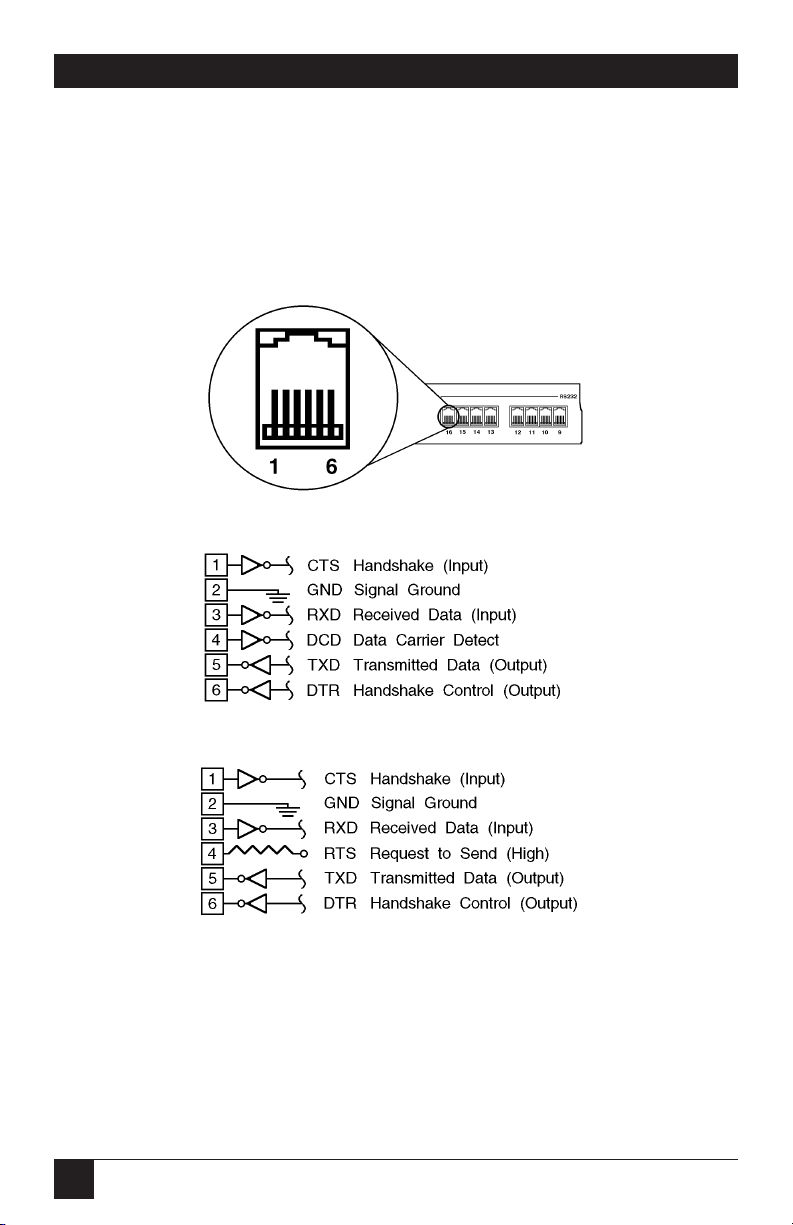
58
PORT MANAGER SWITCHES
Figure A-1 below shows the pin numbering for the Port Manager Switch’s RS-232 ports
(RJ-11 connectors). Figure A-2 below shows the pinout (interface schematic) for ports
1 and 2; Figure A-3 below shows the pinout for ports numbered 3 and higher. Figure
A-4 on the next page shows possible connections using modular adapters built from
kits (our product codes are shown). Figures A-5 and A-6 on pages 58 and 59 show the
pinouts of the adapters included with the PM Switch Tables A-1 through A-4 on the
following pages show the end-to-end pinning you will need to keep in mind when
assembling modular adapters for your application.
Figure A-1. The PM Switch’s RS-232 ports (RJ-11 connectors).
Figure A-2. Circuitry of ports 1 and 2 (Modem Ports).
Figure A-3. Circuitry of ports numbered 3 and higher.
Page 58

59
APPENDIX A: Pinouts
Figure A-4. Possible connections using modular adapter kits.
Figure A-5. The common interface of the PM Switch side
of the modular adapters included with the Switch.
Straight-Through-Pinned Six-Wire
RJ-11 Modular Flat-Satin (EL06MS)
or Twisted-Pair (EYN725MS) Cable
(150 ft. [45.7 m] maximum length)
To Modem
(DCE) or
Printer (DTE)
To Terminal or
IBM PC/XT
compatible PC
(DTE)
To IBM AT
compatible PC
(DTE)
*We do not currently carry DB9↔RJ-11 adapter kits as a stock item. The RJ-45
connectors on the kits shown are 100% backward-compatible with RJ-11.
DB25 male↔
RJ-11 female
(FA024)
DB25 female↔
RJ-11 female
(FA026)
DB9 female↔
RJ-45 female
(FA065)*
Port
Manager
Switch
Modular Adapter
PM Switch Port
RS-232 Port
(RJ-11 female)
Page 59

60
PORT MANAGER SWITCHES
Figure A-6. The pinouts of the device sides
of the modular adapters included with the Switch.
Modular Adapter with
DB25 Female Connector for
PC/XT or Terminal (DTE)
Modular Adapter with
DB25 Male Connector for
Modem (DCE)
Modular Adapter with
DB9 Female Connector for
AT (DTE)
Page 60

61
Table A-1. End-to-End Pinning, PM Switch RS-232 Port to Modem
PM Switch Modem
(RJ-11 female) (DB25 female)
Signal Pin No. Pin No. Signal
Abbrev. Abbrev.
CTS* 1 5 CTS
SGND 2 7 SGND
RD 3 3 RD
RLSD (DCD) 4 8 RLSD (DCD)
TD 5 2 TD
DTR 6 4 RTS
6 DSR
20 DTR
Table A-2. End-to-End Pinning, PM Switch RS-232 Port to
Serial Port of AT Compatible Computer
PM Switch Computer
(RJ-11 female) (DB9 male)
Signal Pin No. Pin No. Signal
Abbrev. Abbrev.
CTS* 1 4 DTR
SGND 2 5 SGND
RD 3 3 TD
RTS 4
TD 5 2 RD
DTR 6 1 RLSD (DCD)
6 DSR
8 CTS
*The PM Switch expects to see the signal on Pin 1 high.
APPENDIX A: Pinouts
Page 61

62
PORT MANAGER SWITCHES
Table A-3. End-to-End Pinning, PM Switch RS-232 Port to
Serial Port of Terminal or PC/XT Compatible Computer
PM Switch Terminal or Computer
(RJ-11 female) (DB25 male)
Signal Pin No. Pin No. Signal
Abbrev. Abbrev.
CTS* 1 20 DTR
SGND 2 7 SGND
RD 3 2 TD
RTS 4
TD 5 3 RD
DTR 6 5 CTS
6 DSR
8 RLSD (DCD)
Table A-4. End-to-End Pinning, PM Switch RS-232 Port to
Input Port of Serial Printer
PM Switch Printer
(RJ-11 female) (DB25 female)
Signal Pin No. Pin No. Signal
Abbrev. Abbrev.
CTS* 1 20 DTR
SGND 2 7 SGND
RD 3 2 TD
RTS 4
TD 5 3 RD
DTR 6 5 CTS
6 DSR
8 RLSD (DCD)
*The PM Switch expects to see the signal on Pin 1 high.
Page 62

63
If you ordered product-code number SW546A-D48, this appendix is relevant
to your Port Manager Switches’s power option.
The 48 Volt DC Power Option (shown below) replaces the standard
117 VAC components on the lower left side of the back panel.
NOTE
Connect -48 Volts DC between the “0” Volt terminal and either of the -48
Volt terminals.
Input Range: 40-60 VDC, 200 milliamps.
Appendix B: SW546A-D48
-48 VOLT INPUTS
0V -48V -48V
AB
Page 63

64
PORT MANAGER SWITCHES NOTES
Page 64

1000 Park Drive • Lawrence, PA 15055-1018 • 724-746-5500 • Fax 724-746-0746
© Copyright 2002. Black Box Corporation. All rights reserved.
 Loading...