

Page 1

1000 Park Drive • Lawrence, PA 15055-1018 • 724-746-5500 • Fax 724-746-0746
© Copyright 1998. Black Box Corporation. All rights reserved.
Page 2

CUSTOMER
SUPPORT
INFORMATION
Order toll-free in the U.S.: Call 877-877-BBOX (outside U.S. call 724-746-5500)
FREE technical support 24 hours a day, 7 days a week: Call 724-746-5500 or fax 724-746-0746
Mailing address: Black Box Corporation, 1000 Park Drive, Lawrence, PA 15055-1018
Web site: www.blackbox.com • E-mail: info@blackbox.com
JANUARY 1998
SW441A-R2 SW443A-R2
SW441AE-R2 SW443AE-R2
SW442A-R2 SW444A-R2
SW442AE-R2 SW444AE-R2
Matrix Switch
PORT
A
B
C
D
D
E
V
I
C
E
1
2
3
4
5
6
7
8
Page 3

3
FCC STATEMENT
FEDERAL COMMUNICATIONS COMMISSION
AND
CANADIAN DEPARTMENT OF COMMUNICATIONS
RADIO FREQUENCY INTERFERENCE STATEMENTS
This equipment generates, uses, and can radiate radio frequency energy
and if not installed and used properly, that is, in strict accordance with the
manufacturer’s instructions, may cause interference to radio
communication. It has been tested and found to comply with the limits for
a Class A computing device in accordance with the specifications in Subpart
B of Part 15 of FCC rules, which are designed to provide reasonable
protection against such interference when the equipment is operated in a
commercial environment. Operation of this equipment in a residential area
is likely to cause interference, in which case the user at his own expense will
be required to take whatever measures may be necessary to correct the
interference.
Changes or modifications not expressly approved by the party responsible
for compliance could void the user’s authority to operate the equipment.
This digital apparatus does not exceed the Class A limits for radio noise emission from
digital apparatus set out in the Radio Interference Regulation of the Canadian
Department of Communications.
Le présent appareil numérique n’émet pas de bruits radioélectriques dépassant les
limites applicables aux appareils numériques de classe A prescrites dans le Règlement
sur le brouillage radioélectrique publié par le ministère des Communications du
Canada.
Page 4

4
INSTRUCCIONES DE SEGURIDAD
NORMAS OFICIALES MEXICANAS (NOM)
ELECTRICAL SAFETY STATEMENT
INSTRUCCIONES DE SEGURIDAD
1. Todas las instrucciones de seguridad y operación deberán ser leídas
antes de que el aparato eléctrico sea operado.
2. Las instrucciones de seguridad y operación deberán ser guardadas
para referencia futura.
3. Todas las advertencias en el aparato eléctrico y en sus instrucciones de
operación deben ser respetadas.
4. Todas las instrucciones de operación y uso deben ser seguidas.
5. El aparato eléctrico no deberá ser usado cerca del agua—por ejemplo,
cerca de la tina de baño, lavabo, sótano mojado o cerca de una alberca,
etc..
6. El aparato eléctrico debe ser usado únicamente con carritos o
pedestales que sean recomendados por el fabricante.
7. El aparato eléctrico debe ser montado a la pared o al techo sólo como
sea recomendado por el fabricante.
8. Servicio—El usuario no debe intentar dar servicio al equipo eléctrico
más allá a lo descrito en las instrucciones de operación. Todo otro
servicio deberá ser referido a personal de servicio calificado.
9. El aparato eléctrico debe ser situado de tal manera que su posición no
interfiera su uso. La colocación del aparato eléctrico sobre una cama,
sofá, alfombra o superficie similar puede bloquea la ventilación, no se
debe colocar en libreros o gabinetes que impidan el flujo de aire por los
orificios de ventilación.
10. El equipo eléctrico deber ser situado fuera del alcance de fuentes de
calor como radiadores, registros de calor, estufas u otros aparatos
(incluyendo amplificadores) que producen calor
.
Page 5

5
INSTRUCCIONES DE SEGURIDAD
11. El aparato eléctrico deberá ser connectado a una fuente de poder sólo
del tipo descrito en el instructivo de operación, o como se indique en el
aparato.
12. Precaución debe ser tomada de tal manera que la tierra fisica y la
polarización del equipo no sea eliminada.
13. Los cables de la fuente de poder deben ser guiados de tal manera que
no sean pisados ni pellizcados por objetos colocados sobre o contra
ellos, poniendo particular atención a los contactos y receptáculos donde
salen del aparato.
14. El equipo eléctrico debe ser limpiado únicamente de acuerdo a las
recomendaciones del fabricante.
15. En caso de existir, una antena externa deberá ser localizada lejos de las
lineas de energia.
16. El cable de corriente deberá ser desconectado del cuando el equipo no
sea usado por un largo periodo de tiempo.
17. Cuidado debe ser tomado de tal manera que objectos liquidos no sean
derramados sobre la cubierta u orificios de ventilación.
18. Servicio por personal calificado deberá ser provisto cuando:
A: El cable de poder o el contacto ha sido dañado; u
B: Objectos han caído o líquido ha sido derramado dentro del
aparato; o
C: El aparato ha sido expuesto a la lluvia; o
D: El aparato parece no operar normalmente o muestra un cambio en
su desempeño; o
E: El aparato ha sido tirado o su cubierta ha sido dañada.
Page 6

6
MATRIX SWITCH
TRADEMARKS USED IN THIS MANUAL
BLACK BOX and the Double Diamond logo are registered trademarks of BB
Technologies, Inc.
Centronics is a registered trademark of Centronics Corporation.
Any other trademarks mentioned in this manual are acknowledged to be the property of the
trademark owners.
Page 7

7
MATRIX SWITCH
Contents
1. Specifications .......................................8
2. Introduction .......................................9
3. Installation . . . .....................................10
3.1 Parallel Installation ..............................10
3.2 Serial Installation . . .............................11
4. Operation .........................................13
Appendix: Serial Pinouts . . .............................14
Page 8

8
MATRIX SWITCH
1. Specifications
Leads Supported
—Serial: 2-6, 8, 15, 17, 19, 20, 22, 24, Pin 7 common;
Parallel: All 25 pins
Speed
—Up to 5 Mbps
Interface
—Serial: RS-232;
Parallel: IBM PC compatible, IEEE Std 1284 compliant, supporting
Compatible and Nibble modes
Connectors
—SW441A-R2, SW441AE-R2: (4) DB25 female input, (4) DB25
male output;
SW442A-R2, SW442AE-R2: (4) male input, (4) female output;
SW443A-R2, SW443AE-R2: (8) DB25 male input, (4) DB25 female output;
SW444A-R2, SW444AE-R2: (8) DB25 female input, (4) DB25 male output
Power
—A-R2 models: Input: 115 VAC, 60 Hz, 16 watts,
Output: 9 VDC, 1A;
AE-R2 models: Input: 230 VAC, 50 Hz, 85 watts,
Output: 9 VDC
Size
—SW441A-R2/AE-R2, SW442A-R2/AE-R2: 3.5"H x 9"W x 7.5"D
(8.9 x 23 x 19.1 cm);
SW443A-R2/AE-R2, SW444A-R2/AE-R2: 3.5"H x 13"W x 7.5"D
(8.9 x 33 x 19.1 cm)
Weight
—SW441A-R2/AE-R2, SW442A-R2/AE-R2: 3.9 lb. (1.8 kg);
SW443A-R2/AE-R2, SW444A-R2/AE-R2: 4.8 lb. (2.2 kg)
Page 9

9
MATRIX SWITCH
2. Introduction
The Matrix Switch enables up to eight microcomputers to share four
peripheral devices. The switch is compatible with all leading brands of
microcomputers and all leading brands of serial and parallel peripherals. A
sense-touch control panel provides instant line configuration. The Switch
supports multiple leads.
Eight models are available:
•4x4Matrix Switch, Serial, 115 VAC, part number SW441A-R2
•4x4Matrix Switch, Serial, 230 VAC, part number SW441AE-R2
•4x4Matrix Switch, Parallel, 115 VAC, part number SW442A-R2
•4x4Matrix Switch, Parallel, 230 VAC, part number SW442AE-R2
•4x8Matrix Switch, Serial, 115 VAC, part number SW444A-R2
•4x8Matrix Switch, Serial, 230 VAC, part number SW444AE-R2
•4x8Matrix Switch, Parallel, 115 VAC, part number SW443A-R2
•4x8Matrix Switch, Parallel, 230 VAC, part number SW443AE-R2
An LED display indicates connections. The Matrix Switch will not allow an
attempt to access an occupied port. Ports must be specifically disconnected
before another connection is made.
Page 10

10
MATRIX SWITCH
3. Installation
Before you begin, make sure that the Matrix Switch is unplugged.
The ports on the serial Matrix Switch units are bidirectional, so that
computers and peripherals may be placed on either ports labeled A-D or 1-
8. This means that either 4 users can share 8 peripherals or 4 peripherals
can be shared among 8 users. Although ports A-D are listed below as
peripheral ports, they may be used to connect to computers instead. The
same is true with the ports labeled 1-8. See the appendix for serial-port
pinouts.
The parallel version of the Switch can have bidirectional IEEE Std 1284-
1994 compliant data transfer, supporting Compatibility and Nibble modes.
Make sure that the computers are communicating properly with the
peripherals directly. Centronics®standard type cables are usually used
when connecting computers to parallel printers. The cable required is
terminated on one end with a Centronics connector and on the other end
with a DB25 connector.
3.1 Parallel Installation
Proceed as follows to install the Matrix Switch in a parallel application:
1. Connect the printers with Centronics type cables (part number
EQN202) to the peripheral ports A through D.
2. Connect the computers to the ports labeled 1 through 8 (or 1 through
4 where applicable) with DB25 type straight-through cables (male and
female connectors, part number EQN201). Note that these cables must
have all 25 wires active and connected to both ends of the cable directly.
If the cable is shielded, make sure that pin 1 is not connected to the
shield.
3. Apply power to the peripherals and computers connected to the Matrix
Switch. You may now power on and use your Matrix Switch unit
normally.
Page 11

11
MATRIX SWITCH
3.2 Serial Installation
Use the following diagram as an aid when connecting PCs and peripherals
to the Matrix Switch.
Figure 3-1. 8 PCs Sharing 2 Modems and 2 Printers (Serial or
Parallel Application).
• Use cable part number ECN25C M/F for the serial input from the PC
and the serial output to the modem.
• Use cable part number BC00901 M/F for the serial output to the
printer.
• Use cable part number EQN201 M/F for the parallel input from the PC.
• Use cable part number EQN202 M/F for the parallel output to the
printer.
PCs
Matrix Switch
Modem
Modem
Printer
Printer
Page 12
12
MATRIX SWITCH
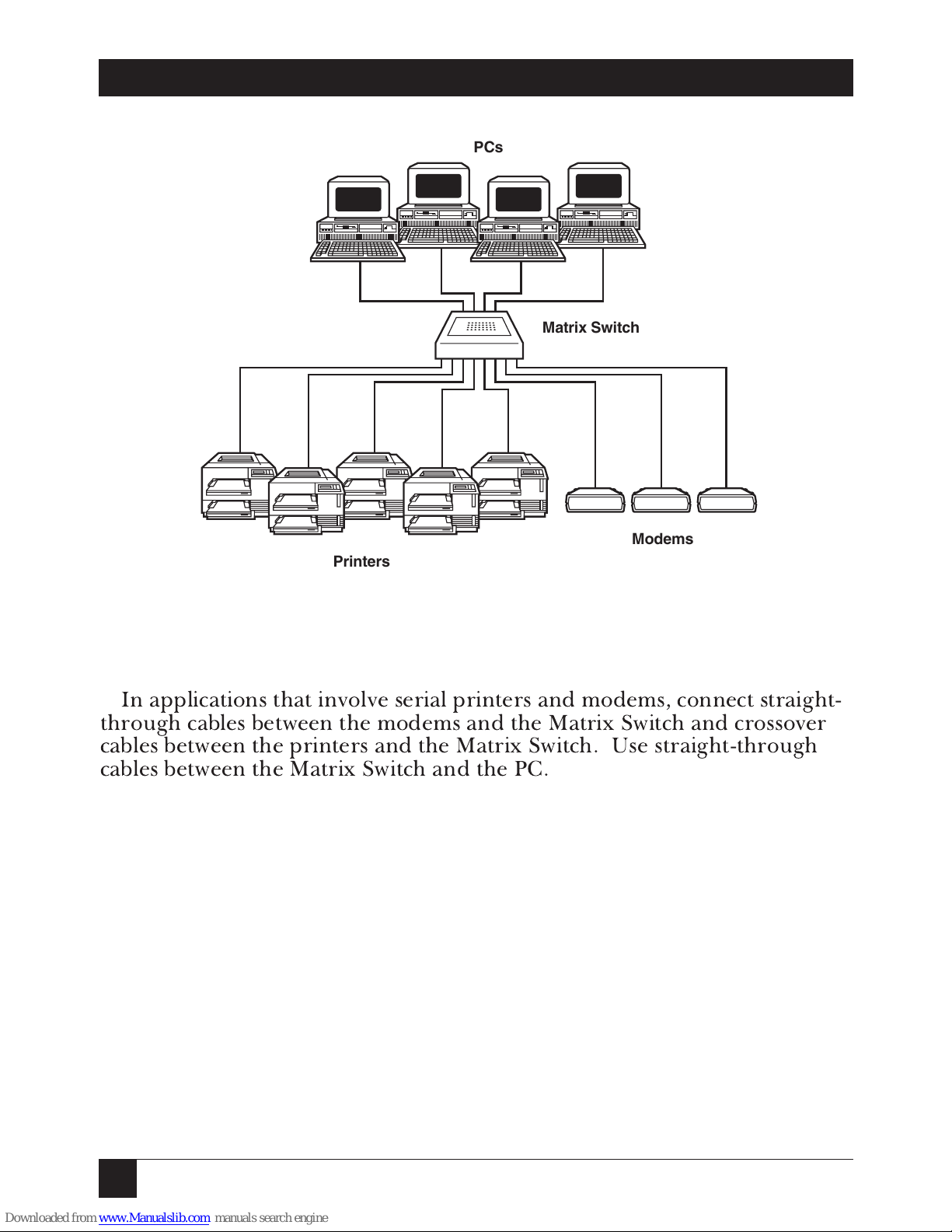
Figure 3-2. 4 PCs Sharing 5 Printers and 3 Modems (Serial
Application Only).
In applications that involve serial printers and modems, connect straight-
through cables between the modems and the Matrix Switch and crossover
cables between the printers and the Matrix Switch. Use straight-through
cables between the Matrix Switch and the PC.
PCs
Printers
Modems
Matrix Switch
Page 13
13
MATRIX SWITCH
4. Operation
There is no power switch on the Matrix Switch. The unit is powered on as
long as the wallmount transformer is plugged into an active AC source.
When the unit is plugged in, a tone will sound for one second to signify a
successful reset. After this, the Matrix Switch will establish any connections
that were present when power was last lost. The indicator LEDs on the
front panel will light as appropriate.
The keypad is located on the top of the unit, with keys labeled 1-8 (or 1-4)
above a column of four LEDs. Each LED indicates a connection between
that input port (1-8 or 1-4) and a particular output port (A-D). When you
press a key, the appropriate LED indicator will advance through the
sequence A, B, C, D, and off (off indicating no connection to any outputs).
When you press a key, the LED will skip any output port that is already
connected to another input port. A connection to an output port must be
disconnected from its input before connecting with another input. When
all four output ports are connected to input ports, no other connection can
be made without first disconnecting an input from an output.
When you press a key, the Matrix Switch emits a short beep.
Under normal circumstances, the Matrix Switch unit should not need to
be reset. If you do need to reset the Switch, unplug the unit for two full
seconds, then plug it back in.
NOTE
The Matrix Switch will reestablish any connections that were present
when power was lost.
Page 14

14
MATRIX SWITCH
Appendix: Serial Pinouts
Table A-1. Serial Pinouts.
Input 1-8 Output A-D
In 2 Out
Out 3 In
In 4 Out
Out 5 In
Out 6 In
Out 7 In
Out 8 In
Out 15 In
Out 17 In
In 19 Out
In 20 Out
Out 22 In
Out 24 In
 Loading...