

Page 1
USER MANUAL
SM260A, SM262A SERIES
2U PRO
SWITCHING
SYSTEM
24/7 TECHNICAL SUPPORT AT 1.877.877.2269 OR VISIT BLACKBOX.COM
A
B
ADDRESS
A
A
B
B
ADDRESS ADDRESS ADDRESS
ADDRESS
A
A
A
A
A
B
B
ADDRESS ADDRESS
B
B
ADDRESS ADDRESS ADDRESS
A
B
B
A
B
A
B
ADDRESS
ADDRESS ADDRESS
A
A
A
B
B
B
ADDRESS
PS1
PS2
p
Page 2

NEED HELP?
LEAV E THE TEC H TO US
LIVE 24/7
TABLE OF CONTENTS
TECHNICAL
SUPPORT
1. 8 7 7. 87 7. 2 269
1. SPECIFICATIONS ........................................................................................................................................................................... 3
2. OVERVIE W ...................................................................................................................................................................................... 5
3. CONFIGURATION .......................................................................................................................................................................... 6
3.1 A/B Switch Configuration ........................................................................................................................................................................ 6
3.2 Controller Card Rear PC Board Configuration ....................................................................................................................................... 7
3.3 Controller Card Front PC Board Configuration ...................................................................................................................................... 9
4. I NSTALLATION ............................................................................................................................................................................ 11
4.1 Controller Card Rear PC Board Installation .......................................................................................................................................... 11
4.2 Controller Card Front PC Board Installation ........................................................................................................................................ 11
4.3 A/B Switch Card Installation ................................................................................................................................................................. 11
5. OPERATION .................................................................................................................................................................................. 12
5.1 RS-232 Serial Switching ......................................................................................................................................................................... 12
5.2 System Switching Using the Gang-In System Control Signal ............................................................................................................ 13
5.3 RS-232 Console Commands (for SNMP/Ethernet Controller Card) .................................................................................................. 13
5.4 Remote Ethernet Management (for SNMP/Ethernet Controller Card) ..............................................................................................15
5.5 Automatic Switching (for SNMP/Ethernet Controller Card) ...............................................................................................................15
5.5.1 Network Connections for Auto Failover and Manual Recovery (FAILOVER Mode) or TOGGLE Mode ..........................................16
5.5.2 Network Connections for Auto Failover and Auto Recovery (FAILOVER Mode) ................................................................................17
6. NETWORK SETUP ....................................................................................................................................................................... 18
7. CONSOLE COMMANDS (SNMP ETHERNET VERSION OF CONTROLLER CARD) .................................................................. 20
8. WEB INTERFACE (SNMP ETHERNET VERSION OF CONTROLLER CARD) ............................................................................. 29
9. SNMP MIB PATH SUMMARY ...................................................................................................................................................... 31
9.1 A/B Switch System SNMP Variable Definitions ..................................................................................................................................32
9.2 A/B Switch System SNMP Trap Definitions ........................................................................................................................................34
10. SYSLOG MESSAGES .................................................................................................................................................................. 36
APPENDIX A. REGULATORY INFORMATION ................................................................................................................................ 38
A.1 FCC Statement .......................................................................................................................................................................................38
A.2 NOM Statement ..................................................................................................................................................................................... 39
APPENDIX B. DISCLAIMER/TRADEMARKS ................................................................................................................................. 40
B.1 Disclaimer ...............................................................................................................................................................................................40
B.2 Trademarks Used in this Manual ............................................................................................................ ..............................................40
2
1. 87 7.8 7 7. 2 26 9 BLACKBOX.COM
Page 3

NEED HELP?
LEAV E THE TEC H TO US
LIVE 24/7
CHAPTER 1: SPECIFICATIONS
TECHNICAL
SUPPORT
1. 8 7 7. 87 7. 2 269
TABLE 1-1. SPECIFICATIONS
Connectors RJ-45 A/B SWITCH CARD – (3) RJ-45 connectors (8 or 10 pin depending on model);
CAT6 RJ-45 A/B SWITCH CARD – (3) CAT6 RJ-45 connectors;
FIBER OPTIC A/B SWITCH CARDS – (3) Duplex fiber optic SC or ST receptacles (FC and LC also
available);
DB9 A/B SWITCH CARD – (3) DB9 female connectors (male optional);
DB15 A/B SWITCH CARD – (3) DB15 female connectors (male optional);
DB25 A/B SWITCH CARD – (3) DB25 female connectors (male optional);
DB25 SIGNAL MONITORING A/B SWITCH CARD – DB25 female (port C), DB25 male (ports A & B);
F-TYPE A/B SWITCH CARD – (3) female F type connectors;
CONTROLLER CARD – (1) RJ-45, (2) RJ-11;
EXTERNAL POWER SUPPLY ADAPTER CARD – (2) two-pin Molex connectors, (2) two-position terminal
blocks;
INTERNAL AC POWER SUPPLY CARD – (1) IEC320 connector, (1) three-position terminal block;
INTERNAL DC POWER SUPPLY CARD – (2) three-position terminal blocks
Indicators A/B SWITCH CARDS – (2) LEDs, one for A, one for B;
CONTROLLER CARD – (2) LEDs, one for power, one for status;
EXTERNAL POWER SUPPLY ADAPTER CARD – (2) LEDs, one power indicator for each external power
supply;
INTERNAL AC or DC POWER SUPPLY CARD – (1) LED, power indicator;
DB25 SIGNAL MONITORING A/B SWITCH CARD – (6) LEDs, A, B, TxD, RxD, RTS, DCD
Switches A/B SWITCH CARDS – (1) momentary toggle switch, (1) 8-position DIP switch;
CONTROLLER CARD – (1) momentary toggle switch, (1) 8-position DIP switch, (1) momentary
push-button switch, and (1) key-lock switch;
DB25 SIGNAL MONITORING A/B SWITCH CARD – (1) momentary toggle switch, (2) 8-position DIP
switch
Ethernet Management Interface
(SNMP/Ethernet Controller Card
only)
Power RJ45 A/B SWITCH CARD – 12 VDC, 40 mA normal, additional 92 mA max while switching;
10BASE-T, Half-Duplex, does not support Auto MDI-X
CAT6 RJ45 A/B SWITCH CARD – 12 VDC, 40 mA normal, additional 92 mA max while switching;
FIBER OPTIC A/B SWITCH CARD, PSEUDO NON-LATCHING – 12 VDC, 40 mA in A position,
120 mA max in B position, additional 13 mA max while switching;
FIBER OPTIC A/B SWITCH CARD, NON-LATCHING – 12 VDC, 40 mA in A position, 133 mA max
in B position;
FIBER OPTIC A/B SWITCH CARD, LATCHING – 12 VDC, 40 mA normal, additional 80 mA max
while switching;
DB9 A/B SWITCH CARD – 12 VDC, 40 mA normal, additional 92 mA max while switching;
DB15 A/B SWITCH CARD – 12 VDC, 40 mA normal, additional 147 mA max while switching;
DB25 A/B SWITCH CARD – 12 VDC, 40 mA normal, additional 239 mA max while switching;
RS-232/DB25 SIGNAL MONITORING A/B SWITCH CARD – 12 VDC, 40 mA normal,
additional 239 mA max while switching;
RS-530/DB25 SIGNAL MONITORING A/B SWITCH CARD – 12 VDC, 100 mA normal,
additional 239 mA max while switching
F-Type A/B SWITCH CARD, LATCHING – 12VDC, 40 mA normal, additional 52 mA max while switching;
F-Type A/B SWITCH CARD, NON-LATCHING – 12VDC, 40 mA in A position, 92 mA max in B position;
CONTROLLER CARD – 12 VDC, 100 mA normal, additional 250 mA with Ethernet module.
The rack may be powered with either a (90 – 264 VAC, 47 – 63 Hz) internal AC supply card, or a (36 –
60 VDC) internal DC supply card, both of which provide 12 VDC, 4.2A max output. The rack may also
be powered with one or two external (90 – 264 VAC, 47 – 63 Hz input, 12 VDC, 5A output) power
supplies using the external power supply adapter card. Two or more power supplies may be used in a
single rack for redundancy.
1. 87 7.8 7 7. 2 26 9 BLACKBOX.COM
3
Page 4

CHAPTER 1: SPECIFICATIONS
TABLE 1-1 (CONTINUED). SPECIFICATIONS
Rack Size RACK – 18 card slots, 3.5” H x 19” W x 12.5” D (including handles and connectors);
RJ-45 A/B SWITCH CARD – one slot (0.937 inches wide);
CAT6 RJ45 A/B SWITCH CARD – one slot (0.937 inches wide);
FIBER OPTIC A/B SWITCH CARDS – one slot (0.937 inches wide);
DB9 A/B SWITCH CARD – two slots (1.875 inches wide);
DB15 A/B SWITCH CARD – three slots (2.812 inches wide);
DB25 A/B SWITCH CARD – three slots (2.812 inches wide);
DB25 SIGNAL MONITORING A/B SWITCH CARD – three slots (2.812 inches wide);
F-TYPE A/B SWITCH CARD – one slot (0.937 inches wide);
CONTROLLER CARD – one slot (0.937 inches wide);
EXTERNAL POWER SUPPLY ADAPTER CARD - one slot (0.937 inches wide);
INTERNAL AC or DC POWER SUPPLY CARD - two slots (1.875 inches wide)
Optical Wavelength 800 through 1600 nm (latching multimode models);
850 and 1310 nm (non-latching multimode models);
1310 and 1550 nm (single mode models)
Insertion Loss 2.0 dB maximum (multimode models);
1.5 dB maximum (single mode models)
Optical Isolation 35 dB minimum (multimode models);
55 dB minimum (single mode models)
Temperat u re Operating: 32 to 104° F (0 to 40° C;
Non-operating: +14 to +158° F (-10 to +70° C)
Humidity Up to 80%, noncondensing
Altitude 40,000 ft. (maximum)
NEED HELP?
LEAV E THE TEC H TO US
LIVE 24/7
TECHNICAL
SUPPORT
1. 8 7 7. 87 7. 2 269
4
1. 87 7.8 7 7. 2 26 9 BLACKBOX.COM
Page 5

NEED HELP?
LEAV E THE TEC H TO US
LIVE 24/7
CHAPTER 2: OVERVIEW
TECHNICAL
SUPPORT
1. 8 7 7. 87 7. 2 269
The 2U Pro Switching System is a 2U 19” rack style chassis containing multiple A/B Switch Cards. Each switch card connects port
A or port B to port C, through latching or non-latching telecommunication relays or fiber optic switch mechanisms. For models
using latching mechanisms, the connection state will be maintained if power fails or is removed. Non-latching versions will revert
to the port C to port A connection state when power is lost, and will remain in that state when power is restored until a new switch
command is received. Pseudo Non-latching fiber optic switch cards fall back to the “Port C to Port A” connection when power fails
or is removed. When power is re-applied, the optical switch in a pseudo non-latching fiber optic switch card will reconnect port C
to the port (A or B) that was selected prior to the loss of power. The non-latching styles of fiber optic switch cards are often used
when a fall-back or “failover” style of connection scheme is desired in the event of power failure.
The 2U rack has 18 slots and can accept any mix of switch cards, power supply cards, and one Controller Card (one required per
chassis). Any type of card can be installed in any slot in the rack, allowing for maximum flexibility of cable routing etc. If a single
slot power supply card is used, the rack can hold up to 16 A/B Switch Cards, and a Controller Card. Each A/B Switch Card can
be individually switched, or the entire rack can be switched from the Controller Card. The Controller Card has a keyed switch to
enable and disable manual switching (disables the front panel toggle switches on the Controller Card and on each switch card).
The Controller Card has two RJ-11 ports that are used for serial communications to the rack, and also allow multiple racks to be
daisy-chained together to create a single system that can be controlled by the first rack in the daisy chain. The Controller Card also
provides remote switching capabilities via an RS-232 interface or using a +/- 12 VDC signal from a remote toggle switch.
The Controller Card consists of a front PC board assembly and a rear PC board assembly set, and is available in three different
versions (RS-232, SNMP/Ethernet, and SNMP Expansion). The RS-232 version supports Rack and System Gang Switching using
the manual toggle switches on the Controller Card and A/B Switch Cards, and supports RS-232 communications on the gang-in
and gang-out connectors. The RS-232 Controller Card allows system level (all cards in all racks) switching with serial commands
(see Section 5.1 for additional info). The SNMP/Ethernet capable version features an RS-232 terminal interface that can be used
to control individual A/B switch cards, a rack of A/B switch cards, or system of daisy-chained racks, and to configure the Ethernet
port parameters (see Section 7 for additional info). The Ethernet port allows the rack or system of daisy-chained racks (containing
the SNMP Expansion Controller Card) to be controlled using SNMP commands, Telnet commands, or via a built-in html based web
browser interface. There can only be one SNMP/Ethernet capable Controller Card in a daisy-chained system of racks, and it must
be in the first rack in the system. If daisy-chaining one or more racks from an SNMP/Ethernet capable rack, the additional racks
must have an SNMP Expansion Controller Card, which is compatible with the message format from the SNMP/Ethernet Controller
Card.
The SNMP/Ethernet Controller Cards also support SNMP traps or syslog messages (user configurable) for various events and
errors, and can send these alerts to as many as 16 different remote monitoring locations.
The SNMP/Ethernet Controller Cards have an intelligent automatic switching capability. This feature allows the switching system
to be used to monitor a specific Ethernet network connection and to automatically switch all ports (performs a system switch
operation) based on whether the monitored IP address responds to ICMP echo requests (responds to PINGs) or not. See Section
5.5 for additional details.
The DB25 Signal Monitoring switch cards are described in a separate manual.
1. 87 7.8 7 7. 2 26 9 BLACKBOX.COM
5
Page 6
CHAPTER 3: CONFIGURATION
NEED HELP?
LEAV E THE TEC H TO US
LIVE 24/7
TECHNICAL
SUPPORT
1. 8 7 7. 87 7. 2 269
3.1 A/B SWITCH CARD CONFIGURATION
A
A
B
B
C
ADDRESS
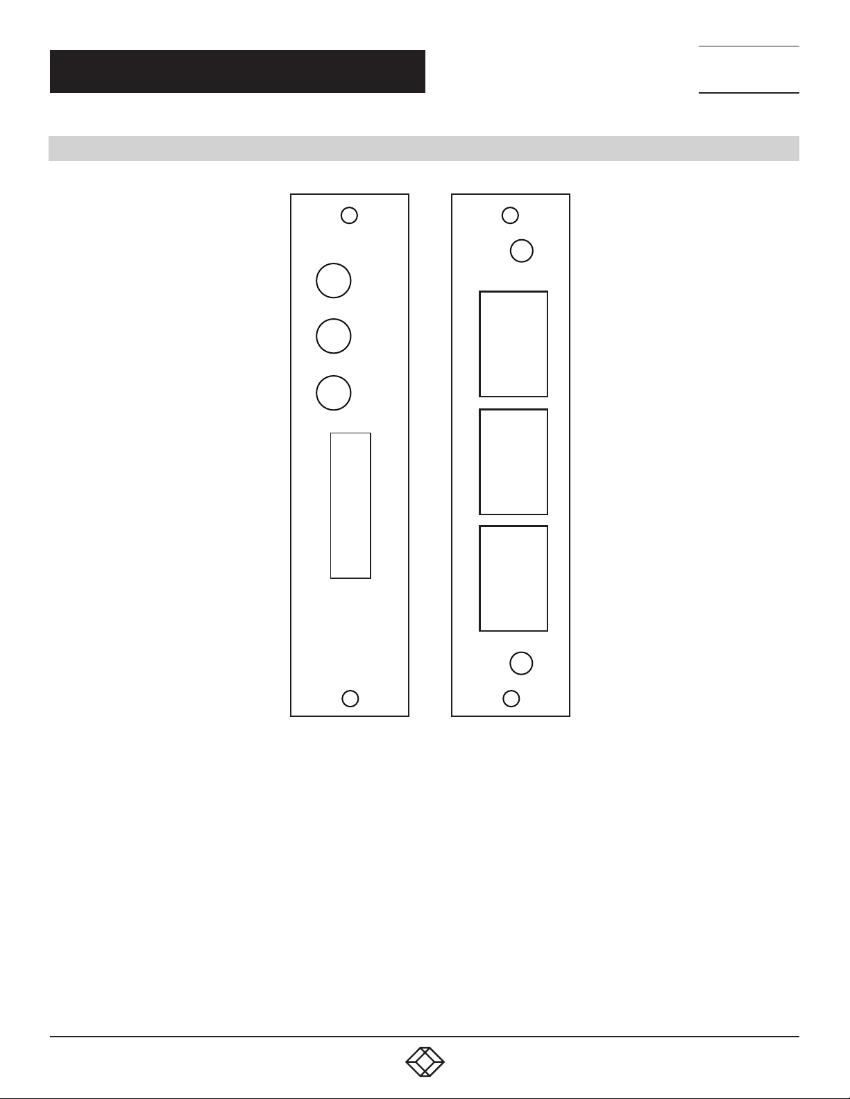
FIGURE 3-1. TYPICAL A/B SWITCH CARD FRONT AND RE AR PANELS
Each A/B Switch Card has an 8-position DIP switch, used to set the card’s address. Switch position 1 is the least significant bit,
and position 8 is the most significant bit. Set each switch ON (as marked) for a ‘0’, and OFF for a ‘1’. Card address 1 for example,
would be DIP switch position 1 OFF, and positions 2-8 ON. Card addresses within a rack, or within a system of daisy-chained racks
must be unique and one card MUST be addressed 1. Card address 0x00 is reserved and must not be used. A typical approach
is to set rack 0x01, card addresses to 0x01 through 0x10 from left to right within the rack. In the second rack 0x02, set the card
addresses to 0x11 through 0x20 and so on. The Controller Card communicates with the individual switch cards using a multi-drop
scheme. If two A/B cards within the same rack or daisy-chained system of racks have the same address, both will try to respond at
the same time, causing communication errors. Thus, the maximum number of A/B Switch Cards in a daisy-chained system of racks
is limited to 255 switch cards.
6
1. 87 7.8 7 7. 2 26 9 BLACKBOX.COM
Page 7
CHAPTER 3: CONFIGURATION
NEED HELP?
LEAV E THE TEC H TO US
LIVE 24/7
TECHNICAL
SUPPORT
1. 8 7 7. 87 7. 2 269
3.2 CONTROLLER CARD REAR PC BOARD CONFIGURATION
NETWORK
8
7
6
5
4
3
2
1
GANG IN
1
2
3
4
5
6
1
2
3
4
5
6
GANG OUT
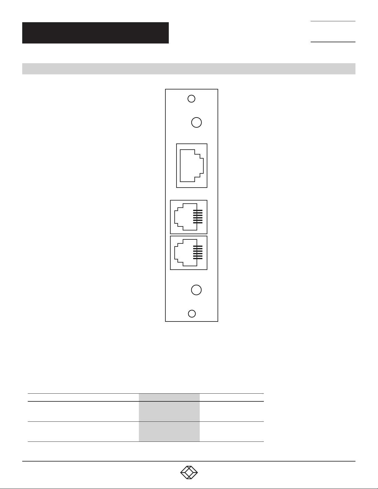
FIGURE 3-2. CONTROLLER CARD REAR PANEL OUTLINE
The Controller Card rear PC board assembly has two jumpers for shielding and grounding options. The two 3-position jumpers are
positioned such that pin 1 is toward the card edge connector, and pin 3 is toward the RJ-11 connectors. Each 3-position jumper has
a 2-position shunt, used to connect two of the three positions together.
TABLE 3-1. CONTROLLER CARD REAR PC BOARD JUMPER SETTINGS
JUMPER W1 W2
RJ-45 Shield
Connected to Frame Ground *
Open
Power Supply Ground
100 Ohm Connection to Frame Ground *
Direct Connection to Frame Ground
*Factory default positions
USB Type B connector —
—
1. 87 7.8 7 7. 2 26 9 BLACKBOX.COM
Pin 1 to Pin 2
Pin 2 to Pin 3
7
Page 8

CHAPTER 3: CONFIGURATION
TABLE 3-2. RJ-45 (OPTIONAL ETHERNET PORT)
PIN ASSIGNMENT
PIN SIGNAL NAME SIGNAL DIRECTION
1 Transmit Pair Output
2 Transmit Pair Output
3 Receive Pair Input
4 Receive Pair Input
TABLE 3-3. RJ-11 GANG-IN PORT PIN ASSIGNMENT
PIN SIGNAL NAME SIGNAL DIRECTION
5 Signal Ground Not applicable
4 Transmit Data / V+ Output/Output
3 Receive Data / V- Input/Output
2 System Control (OPEN, +12, -12) Input and Output
NEED HELP?
LEAV E THE TEC H TO US
LIVE 24/7
TECHNICAL
SUPPORT
1. 8 7 7. 87 7. 2 269
NOTE: The functions of pins 3 and 4, on the GANG-IN port, are set using jumpers on the front card. They can be configured as
TXD and RXD for serial communication, or as V+ and V- to control the system control input with a remote toggle switch. The
connections to V+ and V- are through 1 K ohm resistors. The System Control signal is used as an input and an output. As an Input
signal, it is normally open. This input is driven to +12 VDC to switch the system to A, and is driven to –12 VDC to switch the system
to B. As an output, this signal is driven to +10 VDC when the user initiates a system switch to A, and is driven to –10 VDC when the
user initiates a system switch to B.
TABLE 3-4. RJ-11 GANG-OUT PORT PIN
ASSIGNMENT
PIN SIGNAL NAME SIGNAL DIRECTION
5 No connection Not applicable
4 Transmit Data Output
3 Receive Data Input
2 Signal Ground Not applicable
NOTE: A standard RJ-11 male/male crossover cable is required to connect from the gang-out port on one rack to the gang-in port
on the next.
8
1. 87 7.8 7 7. 2 26 9 BLACKBOX.COM
Page 9

NEED HELP?
LEAV E THE TEC H TO US
LIVE 24/7
CHAPTER 3: CONFIGURATION
3.3 CONTROLLER CARD FRONT PC BOARD CONFIGURATION
The Controller Card front PC board has an 8-position DIP switch and four jumpers for user configurable options. The four
3-position jumpers are positioned such that pin 1 is toward the front panel, and pin 3 is toward the rear of the card. Each 3-position
jumper has a 2-position shunt, used to connect two of the three positions together.
TABLE 3-5. CONTROLLER CARD FRONT PC BOARD JUMPER W1 AND W2 SETTINGS
JUMPER W1 W2
Gang-In Pin 3
Connected to TXD *
Connected to V+ through 1K
Gang-In Pin 4
Connected to RXD *
Connected to V- through 1K
*Factory Default Setting
Pin 1 to Pin 2
Pin 2 to Pin 3
—
—
Pin 1 to Pin 2
Pin 2 to Pin 3
TECHNICAL
SUPPORT
1. 8 7 7. 87 7. 2 269
Jumpers W1 and W2 function as a pair to configure the gang-in port. Refer to Table 3-3 for the GANG-IN port pin assignment.
Connect to TXD and RXD to support RS-232 serial communications, or connect to V+ and V- through 1 K ohm resistors to control
the system control input with a remote toggle switch.
NOTE: The serial port is required for setup of the network parameters.
TABLE 3-6. CONTROLLER CARD FRONT PC BOARD JUMPER W4 AND W5 SETTINGS
JUMPER W4 W5
Input Port Source
Normal RS-232 *
Optional SNMP/Ethernet version **
Input Port Source
Normal RS-232 *
Optional SNMP/Ethernet version **
* Factory Default Setting – RS-232 and SNMP Expansion versions
** Factory Default Setting – SNMP/Ethernet version
Jumpers W4 and W5 function as a pair to congure the input port source. It should not be necessary to change these jumpers from
their factory set positions. These jumpers congure the source for communications to the internal processor on the Controller Card.
If you have a Controller Card with an optional SNMP/Ethernet module installed, both jumpers should be set to connect pins 2 and 3.
Otherwise, both jumpers should be set to connect pins 1 and 2 to allow the processor to communicate with the RS-232 signals from
the GANG-IN port.
The 8-position DIP switch has a different function depending on the type of Controller Card. Refer to Table 3-7 for the RS-232 version
only.
For the SNMP/Ethernet and SNMP Expansion Controller Cards, the 8-position DIP switch SW2 is used to dene the Controller Card
(or rack) address. Rack addresses within the system must be unique, but may be repeated in other systems. The rack address space
and card address space are separate, i.e. racks and cards can have the same address. Address “00” must be left unused, and we
recommend that the racks be assigned addresses “01” through “FF”. If two racks within the same system have the same address,
both will try to respond at the same time, causing communication errors. Switch position 1 is the least signicant bit, and position 8
is the most signicant bit. Set each switch ON (as marked) for a ‘0’, and OFF for a ‘1’. Address 1 for example would be position 1 OFF,
and positions 2-8 ON.
Pin 1 to Pin 2
Pin 2 to Pin 3
—
—
Pin 1 to Pin 2
Pin 2 to Pin 3
1. 87 7.8 7 7. 2 26 9 BLACKBOX.COM
9
Page 10

NEED HELP?
LEAV E THE TEC H TO US
LIVE 24/7
CHAPTER 3: CONFIGURATION
The SNMP/Ethernet Controller Cards can be supplied with special “universal” rmware that allows the Ethernet management
interface to be enabled or disabled depending on the address DIP switch setting. When the rack address DIP switch is set to address
“1” (binary 00000001), the Ethernet interface is enabled and the unit operates as a normal SNMP/Ethernet Controller Card. If the
rack address DIP switch is set to address 2 or higher, the Ethernet interface is disabled and the unit operates like a SNMP Expansion
Controller Cards, allowing it to be daisy-chain connected to the GANG-OUT port of another SNMP/Ethernet or SNMP Expansion
Controller Card. Please contact Black Box for additional information regarding the universal rmware.
TABLE 3-7. CONTROLLER CARD DIP SWITCH SETTINGS
(RS-232 VERSION ONLY)
SWITCH SW2-1 SW 2-2 S W2-3 SW2-4 SW2-5 SW2-6
0 ON ON ON ON — —
1 OFF ON ON ON — —
2 ON OFF ON ON — —
3 OFF OFF ON ON — —
4 ON ON OFF ON — —
5 OFF ON OFF ON — —
6 ON OFF OFF ON — —
7 OFF OFF OFF ON — —
8 ON ON ON OFF — —
9 OFF ON ON OFF — —
: ON OFF ON OFF — —
; OFF OFF ON OFF — —
< ON ON OFF OFF — —
= OFF ON OFF OFF — —
> ON OFF OFF OFF — —
? OFF* OFF* OFF* OFF* — —
Security Code Enabled — — — — ON —
Security Code Disabled — — — — OFF* —
Safe Mode Enabled — — — — — ON
Safe Mode Disabled — — — — — OFF*
TECHNICAL
SUPPORT
1. 8 7 7. 87 7. 2 269
*Factory Default Setting
When the security code is enabled (SW2-5 set to ON), the selected security character must precede any serial commands received
at the gang in port of the first rack in the system. The security code must be disabled on all following racks. Refer to Section 5.1 for
a list of applicable serial commands.
Safe mode operation (SW2-6 set to ON) prevents switching commands from the gang-in port, allowing only status request
commands. This provides a level of protection against corrupt or spurious data causing unintended switching in an application
where only status is required of the gang-in port. Set safe mode OFF to allow A/B switching from the gang-in serial port. Safe mode
must be disabled (OFF) on racks connected to the gang-out port of another rack, to allow system switching to occur (otherwise,
system switching will be blocked from higher level racks).
DIP switch positions 7 and 8 are reserved for future development, and should be left in the OFF position.
10
1. 87 7.8 7 7. 2 26 9 BLACKBOX.COM
Page 11

NEED HELP?
LEAV E THE TEC H TO US
LIVE 24/7
CHAPTE R 4: INSTA LL ATION
TECHNICAL
SUPPORT
1. 8 7 7. 87 7. 2 269
The A/B Switch Cards consist of a single card, which is inserted from the rear of the rack. The Controller Card consists of a front
card and a rear card.
4.1 CONTROLLER CARD REAR PC BOARD INSTALLATION
STEP 1: Using the card guides, carefully slide the rear card into the rack, until it makes connection to the 8-position socket on the
rack backplane.
STEP 2: Secure the rear card to the rack at the top and bottom of the card, using the screws provided.
STEP 3: Using a standard RJ-11 male/male crossover cable, connect the gang out from one rack to the gang in connector on the
next if multiple racks are to be daisy-chained together. Repeat this step until all racks have been connected.
4.2 CONTROLLER CARD FRONT PC BOARD INSTALLATION
STEP 1: Using the card guides, carefully slide the front card into the rack, until it makes connection to the 36-position card edge
connector on the rear card.
STEP 2: Secure the front card to the rack at the top and bottom of the card, using the screws provided.
4.3 A/B SWITCH CARD NSTALLATION
STEP 1: From the rear of the rack, using the card guides, carefully slide the card into the rack, until it makes connection to the
8-position socket on the rack backplane.
STEP 2: Secure the rear card to the rack at the top and bottom of the card, using the screws provided.
STEP 3: If not already in place, secure the front panel to the rack, using the screws provided.
1. 87 7.8 7 7. 2 26 9 BLACKBOX.COM
11
Page 12

NEED HELP?
LEAV E THE TEC H TO US
LIVE 24/7
CHAPTER 5: OPERATION
When power is applied to the Controller Card, the PWR LED should illuminate.
When power is applied to the A/B Switch Card, either the “A” LED or the “B” LED should illuminate to indicate the currently
connected port.
When the Key-Lock switch on the Controller Card is OFF, the manual toggle switches on the Controller Card and all the A/B Switch
Cards in the rack will be disabled.
NOTE: The rack may still switch in response to a command received on the RS-232 Gang-In port, or the Ethernet port.
When the Key-Lock switch on the Controller Card is ON, the manual toggle switches in the rack function normally.
The toggle switches on the A/B Switch Cards are used to switch only that card. Hold the switch in the “A” position to connect Port
A to Port C. The “A” LED will illuminate when the switch operation has been completed. Release the switch when switching has
finished. Hold the switch in the “B” position to connect Port B to Port C. The “B” LED will illuminate when the switch operation has
been completed. Release the switch when switching has finished.
The toggle switch on the Controller Card is used to switch all cards in the rack, and is operated in the same fashion as the individual
toggle switches on the A/B Switch Cards. To switch an entire system of daisy-chained racks, hold the “system” push-button while
operating the toggle switch on the Controller Card.
The Controller Card STAT LED should blink under the following conditions:
The front panel control switches are used to initiate a “rack” or “system” level switching operation.
The Controller Card received a switch command on the RS232 Gang-In port or the Ethernet port.
TECHNICAL
SUPPORT
1. 8 7 7. 87 7. 2 269
5.1 RS-232 SERIAL SWITCHING
The RS-232 version of the Controller Card allows the user to remotely switch all of the cards in a rack or system of daisy-chained
racks using the serial commands listed in Table 5-1. The SNMP/Ethernet version of the Controller Card does not support the one
character serial commands listed in Table 5-1, but instead uses the enhanced console commands listed in Section 7 of this manual.
Also note that the data rate of the Gang-In port increases to 9600 bps for the SNMP/Ethernet version of Controller Card. The SNMP
Expansion Controller Card does not support the one character serial commands listed in Table 5-1, but will pass these commands
through to the cards in the rack and to subsequent racks in the system.
TABLE 5-1. RS-232 SYSTEM SWITCHING COMMANDS (RS-232 VERSION OF CONTROLLER CARD)
COMMAND DESCRIPTION
A <CR> Switch system to A
B <CR> Switch system to B
C <CR> Request status
NOTES:
1. The RS-232 terminal device connected to the RS-232 version of Controller Card’s Gang-In port must be set to 2400 Baud, No
Parity, 8 Data Bits, 1 Stop Bit. Connect using the supplied DB9 to RJ-11 adapter and RJ-11 to RJ-11 crossover cable.
2. The one-character commands above are CASE SENSITIVE, and must be followed by a carriage return. Refer to Table 3-7 for a list
of optional “security” characters that may precede these commands.
NOTE: These RS-232 commands only allow control of the entire system, thus the status of all cards in the system should be the
same. Therefore, only one card (address 0x01) in the first rack will respond to the “S” status command. If there is no card with
address 0x01 in the first rack, there will be no response to the status command.
12
1. 87 7.8 7 7. 2 26 9 BLACKBOX.COM
Page 13
NEED HELP?
LEAV E THE TEC H TO US
LIVE 24/7
CHAPTER 5: OPERATION
TECHNICAL
SUPPORT
1. 8 7 7. 87 7. 2 269
5.2 SYSTEM SWITCHING USING THE GANG-IN SYSTEM CONTROL SIGNAL
The System Control signal is used as an input and an output. As an Input signal it is normally open. This input is driven to +12 VDC
to switch the system to A, and is driven to -12 VDC to switch the system to B. The input circuit requires approximately 1 mA to
operate properly.
As an output, this signal is driven to +10 VDC when the user initiates a system switch to A, and is driven to –10 VDC when the user
initiates a system switch to B. To protect the output circuits, the output goes through a 1 K ohm resistor. Therefore, this output
should not be used to drive a large load.
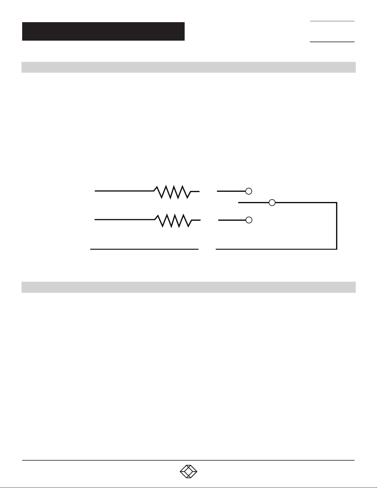
The gang-in connector normally accepts RS-232 input signals, but can be configured to supply +12 VDC and -12 VDC. Refer to Table
3-5 for jumper configuration information. These +12 VDC and -12 VDC outputs are provided through 1 K ohm resistors, and therefore
should not be used to drive large loads. These outputs are provided to allow system switching, using only a remote contact. We
recommend using a momentary toggle switch.
Momentary
+12VDC
1K OHM
PIN4
Toggle Switch
1K OHM
-12VDC
PIN3
PIN2
System Control
FIGURE 5-1. SYSTEM SWITCHING USING A REMOTE MOMENTARY TOGGLE SWITCH
5.3 RS-232 CONSOLE COMMANDS (FOR SNMP/ETHERNET CONTROLLER CARD)
This section is applicable to SNMP/Ethernet Controller Cards. The GANG-IN RS-232 interface on the SNMP/Ethernet Controller
Card operates at 9600. The GANG OUT interface operates at 2400 bps. This allows the GANG OUT interface to connect to the GANG
IN port on another rack (that does not have the Ethernet Module installed) so that multiple racks can be daisy-chain connected
together. When daisy chaining multiple racks, only the first rack in the chain may have an Ethernet Module installed.
SNMP/Ethernet Controller Cards support an enhanced set of serial commands that are listed below and described in more detail
in Section 7. To communicate with the internal Ethernet module, set your RS-232 terminal to 9600 baud, no parity, 8 data bits, and
1 stop bit. Connect this terminal to the GANG-IN RS232 interface on the SNMP/Ethernet Controller Card using the DB9 to RJ-11
adapter and RJ-11 crossover cable provided with the SNMP/Ethernet Controller Card.
When you apply power to the system, the Ethernet module runs a series of internal self tests and configuration steps. This takes
approximately 5 seconds. After this process is complete you will see a sign-on message displayed on your serial console, similar to
the following:
Network Agent Version 2.9X JUN 2018
Copyright (c) 2018
All rights reserved
System starting ...
Rack position A
Console ready
>
1. 87 7.8 7 7. 2 26 9 BLACKBOX.COM
13
Page 14

NEED HELP?
LEAV E THE TEC H TO US
LIVE 24/7
CHAPTER 5: OPERATION
At this point, the Ethernet module is now ready to receive RS-232 serial commands via the GANG IN connector. If you type
“help” followed by the ENTER KEY, the list of available commands will be displayed as shown below. See Section 7 for a detailed
description of each command.
CONSOLE COMMANDS:
GET ALL (display all parameters)
GET VERSION (display rack 1 software versions)
GET VERSION N (display rack N software versions)
GET[SET] SYSTEM [A/B] (control all system ports)
GET[SET] RACK N [A/B] (control rack N ports)
GET[SET] PORT N [A/B] (control port N)
GET POWER N (display rack N power status)
GE T[S ET] IPA D DRESS [X.X.X.X]
GE T[S ET] S U B N ET M A SK [X.X.X.X]
GE T[S ET] G ATEWAY [X.X.X.X]
GET[SET] PINGREPLY [ON/OFF]
GET[SET] SNMPENABLE [ON/OFF]
GET[SET] READCOMMUNITYNAME [string]
GET[SET] WRITECOMMU NITYNAME [string]
GET[SET] WEBENABLE [ON/OFF]
GET[SET] WEBPASSWORD [string]
GET[SET] WEBTIMEOUT [N] (seconds)
GET[SET] WEBPORT [N]
GET[SET] TELNETENABLE [ON/OFF]
GET[SET] TELNETPASSWORD [string]
GET[SET] TELNETTIMEOUT [N] (seconds)
GET[SET] TELNETPORT [N]
GET[SET] MONITORIP [X.X.X.X] (0.0.0.0 to disable)
GET[SET] MONITORMAC [X X X X X X] (X = HEX CHARS)
GET[SET] MONITORMODE [FAILOVER/TOGGLE]
GET[SET] MONITORDELAYCOUNT [N]
GET[SET] MONITORINTERVAL [N] (1/10 seconds, 0 to disable)
GET[SET] MONITORFAILCOUNT [N] (0 to disable)
GET[SET] MONITOROKCOUNT [N] (0 = no auto recover)
GET[SET] AUTHEN TICATIONTRAP [ON/OFF]
GET[SET] ALERTTYPE [TRAP/SYSLOG]
GET[SET] ADMINIP N [X.X.X.X] (0.0.0.0 to disable an entry)
GET ADMINIP (display all administrator IP addresses)
GET[SET] MANAGER N [X.X.X.X] (0.0.0.0 to disable an entry)
TECHNICAL
SUPPORT
1. 8 7 7. 87 7. 2 269
14
1. 87 7.8 7 7. 2 26 9 BLACKBOX.COM
Page 15

NEED HELP?
LEAV E THE TEC H TO US
LIVE 24/7
CHAPTER 5: OPERATION
TECHNICAL
SUPPORT
1. 8 7 7. 87 7. 2 269
GET MANAGER (display all SNMP managers)
PING X.X.X.X (ICMP ECHO to remote host)
SAVE save settings for next startup
RESET restart (use after SAVE)
SET DEFAULTS (restore default user settings, save required)
5.4 REMOTE ETHERNET MANAGEMENT (FOR SNMP/ETHERNET CONTROLLER CARD)
To use the Ethernet network port, you must set the IPADDRESS, SUBNETMASK and GATEWAY address of the internal Ethernet
module before connecting to your network. See Section 7 for more details.
The internal Ethernet module allows remote management of the switching system via SNMP, Telnet, or web browser. The SNMP
interface allows access to the MIB variables described in Section 9. SNMP is also used by SwitchCenter, the java based graphical
user interface application provided with the SNMP/Ethernet Controller Card. The Telnet and web browser interfaces provide access
to the console commands described in Section 7. Each of these remote management interfaces may be enabled or disabled.
The SAVE command is used to cause the internal Ethernet module to store the configuration parameters in non-volatile memory. If
the Ethernet module is reset before performing a SAVE command, configuration changes will be lost.
5.5 AUTOMATIC SWITCHING (FOR SNMP/ETHERNET CONTROLLER CARD)
The SNMP/Ethernet Controller Card can be configured to automatically switch the connection state: all COMMON ports are
connected to their respective A ports or all COMMON ports are connected to their respective B ports. To be able to perform the
auto-switching functions, the internal Ethernet module issues ICMP echo request (PING) packets to a user-configurable IP address
on the network.
The auto-switching function can be configured to operate in one of two modes. In FAILOVER mode (the default mode), the autoswitching function switches to the “failover” or “bypass” connection state (all COMMON ports are connected to their respective
A ports) when PING responses are not received, and if configured to “auto recover” it switches to the “normal” connection state
(all COMMON ports are connected to their respective B ports) when PING responses are received. In TOGGLE mode, the autoswitching function toggles the connection state from A to B or from B to A when PING responses are not received, and maintains
the connection state (all COMMON ports are connected to their respective A ports or B ports) when PING responses are received.
User configurable parameters control the auto-switching functions to allow the switch to be used in a variety of applications.
In FAILOVER mode, if the “normal” network path connections between the Ethernet module and the device being monitored go
down for any reason, the Ethernet module will no longer be able to PING the specified IP address, and will then automatically switch
from the “normal” connection state (all COMMON ports are connected to their respective B ports) to the “bypass” or “failover”
connection state (all COMMON ports are connected to their respective A ports). Once the problems on the primary path have
been identified and corrected, the user can issue a command to cause the rack to switch from the failover connection state back
to the normal connection state. If auto recovery is enabled, the Ethernet module will automatically re-connect the normal path
connections when it is again able to PING the user specified IP address. When using the auto recovery feature, it is important that
the Ethernet network port on the rack be connected to the user’s network so that the normal path is continuously being monitored
even when the backup path has been selected; otherwise, the switching system could repeatedly switch (flap) back and forth
between the failed primary path and the functioning backup path.
1. 87 7.8 7 7. 2 26 9 BLACKBOX.COM
15
Page 16
NEED HELP?
LEAV E THE TEC H TO US
LIVE 24/7
CHAPTER 5: OPERATION
In TOGGLE mode, if the “current” network path connections between the Ethernet module and the device being monitored go down
for any reason, the Ethernet module will no longer be able to PING the specified IP address, and will then automatically switch to
the “alternate” connection state, trying to restore successful PING responses. In this mode, the auto-switching function will toggle
between all COMMON ports are connected to their respective A ports and all COMMON ports are connected to their respective B
ports, until it receives responses to its PING requests. The rack will then remain in the current connection state (all COMMON ports
are connected to their respective A ports or B ports), until the user issues a command to cause the rack to switch connections, or
should the Ethernet module fail to receive PING responses. When in TOGGLE mode, it is important that the rack’s remote control
Ethernet network port be connected to the user’s network so that the current path is being monitored.
When the auto switching feature is enabled, manual and remote switching can still be performed using the front panel toggle switch
or by issuing serial or Ethernet commands, but this can affect the operation of the automatic switching feature. This is because
the automatic switching feature is only aware of “system level” commands, i.e. “SET SYSTEM A”, “SET SYSTEM B”, and manual
switching using the front panel toggle switch while holding in the “SYSTEM” pushbutton switch. If the user initiates any of these
“system level” commands, the switching system will execute the command and the automatic switching feature will record the new
connection state. The automatic switching feature will then continue to monitor the connection path to the selected IP address and
will automatically switch connections as it normally would.
However, if the switching system receives a “SET RACK” command, or if the rack is switched using the front panel toggle switch
without holding in the “SYSTEM” pushbutton switch, these commands will not be recorded by the automatic switching feature
—it will be unaware that the switching system has changed connection states. Under certain conditions when in this state, the
automatic switching feature will not automatically switch connection states as expected, because it “thinks” that it is already in the
correct connection state. To recover from this condition, the user can either power cycle the SNMP/Ethernet Controller Card, issue
a “RESET” command, or execute a “system level” command. Any of these actions will cause the automatic switching feature to
record the current connection state of the switch, which then allows it to again operate normally.
Connection changes made using the “SET PORT” command also are not recorded by the automatic switching feature. Thus, under
certain conditions, the automatic switching feature will not automatically switch connection states as described above when “rack
level” commands are issued.
TECHNICAL
SUPPORT
1. 8 7 7. 87 7. 2 269
5.5.1 NETWORK CONNECTIONS FOR AUTO FAILOVER AND MANUAL RECOVERY (FAILOVER MODE)
OR TOGGLE MODE
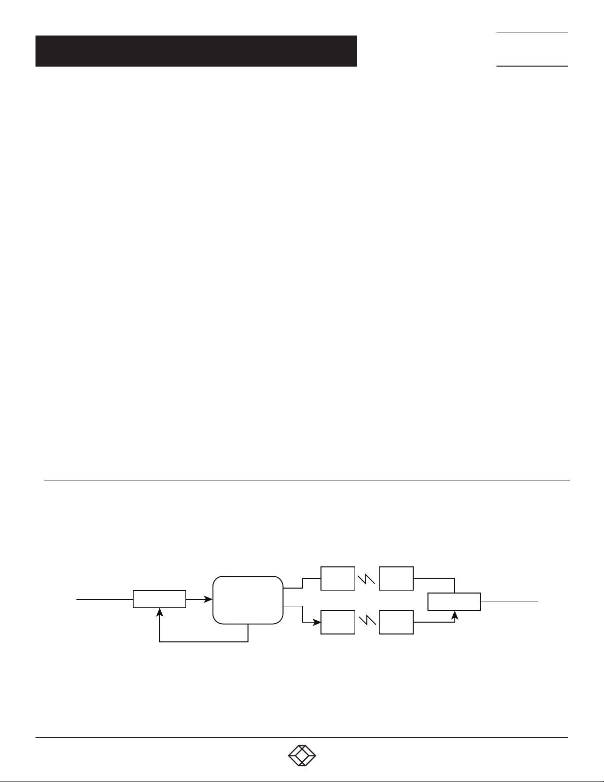
NOTE: The 2U Pro Switching System monitors the WAN connections by PINGing the far side router through the primary WAN link. in
FAILOVER mode, if the primary WAN link fails, the SM260A auto switches to the backup WAN link. Auto recovery is disabled in this
conguration to prevent apping. In TOGGLE mode, if the selected WAN link fails, the rack will toggle between the primary and the
backup WAN until a working link is established.
SM260A
Network 1
router
1.1.10.1
C
PING 2.2.20.1
Network
Port
A
B
FIGURE 5-2. NETWORK CONNECTIONS FOR AUTO FAILOVER AND MANUAL RECOVERY (FAILOVER MODE) OR TOGGLE MODE
backup
WAN
primary
WAN
backup
WAN
primary
WAN
router
2.2.20.1
Network 2
16
1. 87 7.8 7 7. 2 26 9 BLACKBOX.COM
Page 17
NEED HELP?
LEAV E THE TEC H TO US
LIVE 24/7
CHAPTER 5: OPERATION
TECHNICAL
SUPPORT
1. 8 7 7. 87 7. 2 269
5.5.2 NETWORK CONNECTIONS FOR AUTO FAILOVER AND AUTO RECOVERY (FAILOVER MODE)
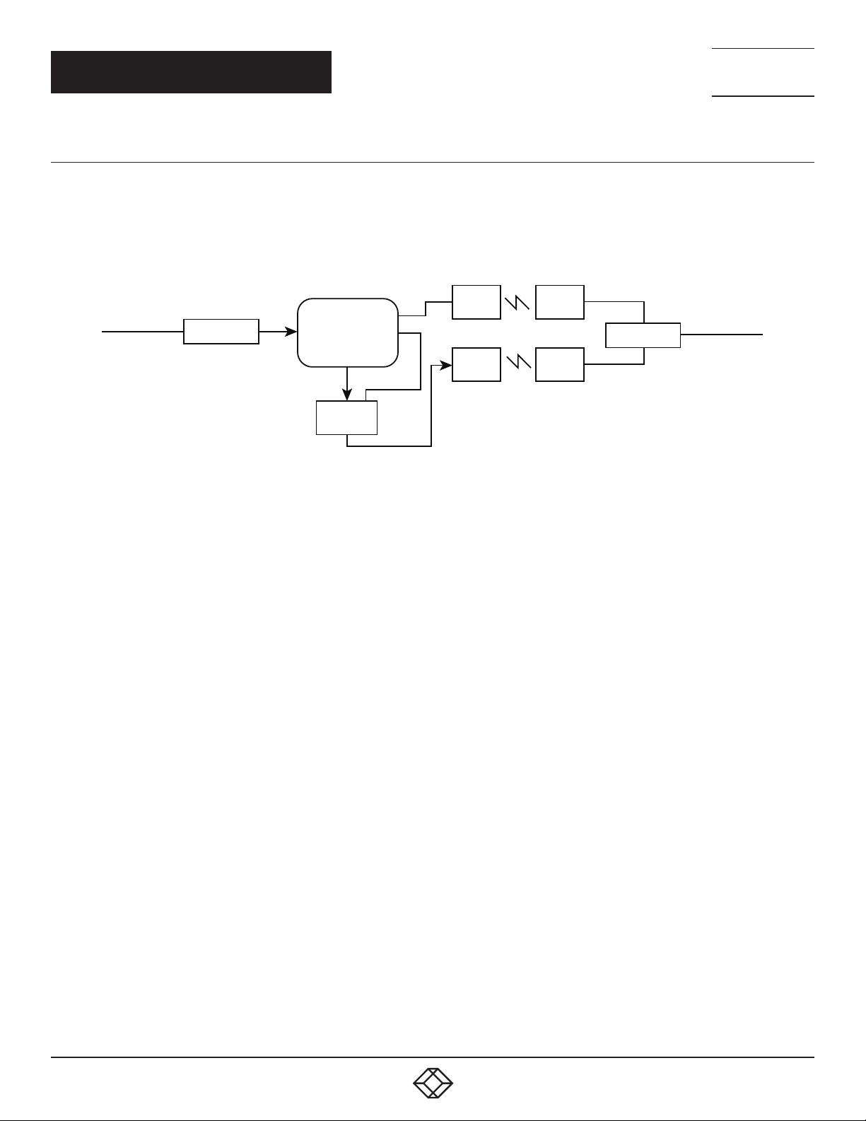
NOTE: The 2U Pro Switching System monitors the WAN connections by PINGing the far side router through the primary WAN link. If
the primary WAN link fails, the SM260A switches to the backup WAN link. When the primary WAN link is available again, the rack auto
switches back to the primary WAN path. This conguration will not function properly in TOGGLE mode, since the connection between
the rack’s remote control Network Port and the far side router is not affected by switching the C port connection state.
Network 1
router
1.1.10.1
C
PING 2.2.20.1
SM260A
Network
Port
E/N
hub/switch
A
B
backup
WAN
primary
WAN
backup
WAN
primary
WAN
router
2.2.20.1
Network 2
FIGURE 5-3. NETWORK CONNECTIONS FOR AUTO FAILOVER AND AUTO RECOVERY (FAILOVER MODE)
In most network environments, you can configure the Ethernet module to automatically determine the proper MAC address required
for the PING packet. Enter the monitor ip address of the device to be monitored, and leave the monitor mac address parameter set
to the default value 00 00 00 00 00 00. This causes the Ethernet module to issue an ARP request to determine the appropriate MAC
address for the PING packet. To eliminate the ARP request, enter the monitor mac address as follows. If the monitored device is on
the same subnet as the Ethernet module, set the monitor mac address to the MAC address of the monitored device. If the monitored
device is on a different subnet than the Ethernet module, set the monitor mac address to the MAC address of the gateway router, so
the gateway router can route the PING packet to the target device on a different subnet.
1. 87 7.8 7 7. 2 26 9 BLACKBOX.COM
17
Page 18

NEED HELP?
LEAV E THE TEC H TO US
LIVE 24/7
CHAPTER 6: NETWORK SETUP
To perform the initial setup of an SNMP/Ethernet version of Controller Card, you will need a serial terminal capable of 9600 baud, no
parity, 8 data bits, and 1 stop bit. Connect this terminal to the GANG-IN port using the supplied DB9 to RJ-11 adapter and RJ-11 to
RJ-11 crossover cable.
TABLE 6-1. DB9 TO RJ-11 ADAPTER PIN ASSIGNMENT
RJ-11 PIN SIGNAL NAME SIGNAL DIRECTION DB9 PIN
3 Receive Data To Termi n al 2
4 Transmit Data From Te rmina l 3
2 Ground — 5
Apply power to the rack. The SNMP/Ethernet version of Controller Card requires about 5 seconds to boot up, while performing self
tests and configuring.
After this process is complete you will see a sign-on message displayed on the serial console, i.e.
Network Agent Version 2.9X JUN 2018
Copyright (c) 2018
All rights reserved
System starting ...
Rack position A
Console ready
>
At this point, the Controller Card is ready for the low-level configurations necessary before you will be able to communicate with the
network port using TCP/IP. You will need to enter an IP address, subnet mask, and gateway address, as well as read and write SNMP
community names if using SNMP, a telnet password for telnet access, or a web password for browser access. These parameters
must be saved into non-volatile memory, and then the system must be reset to allow it to reconfigure with the new settings. Any
time one or more of these parameters is changed, they must be saved followed by a system reset. The following shows a typical
setup session. Change the entered parameters to suit your application requirements. All the console level commands available are
described in detail in Section 7.
TECHNICAL
SUPPORT
1. 8 7 7. 87 7. 2 269
> s e t ip add r ess 192.168.1.200
IP Ad d re s s: 192.168.1.200
> s e t s u b n et ma s k 255.255.255.0
Su bnet M a sk: 2 55.255.255.0
> s e t gat e way 192.16 8.1.1
G ate w a y IP A d d re s s: 192.168.1.1
>set readcommunityname public
Read Community Name: public
>s et w ritec o m m u nity n ame private
Write Community Name: private
18
1. 87 7.8 7 7. 2 26 9 BLACKBOX.COM
Page 19

NEED HELP?
LEAV E THE TEC H TO US
LIVE 24/7
CHAPTER 6: NETWORK SETUP
>save
Saving user data, please wait.
Save complete.
>reset
r e s e t t i n g, p le a s e w a i t ...
After the system reinitializes, you will again be greeted by the sign-on message as before. At this time, you can attach a 10BASE-T
CAT5 cable between the Controller Card’s Network port and an available port on your Ethernet hub or switch/router. The SNMP/
Ethernet version of the Controller Card will now respond to telnet, SNMP and/or HTTP messages at the assigned IP address,
depending on which options are enabled. Section 7 describes the commands that are available via the console prompt (telnet, web, or
RS-232 interface). Section 8 describes the operation of the web browser interface, and Section 9 provides a MIB Path Summary that
lists the supported SNMP variables and their functions.
TECHNICAL
SUPPORT
1. 8 7 7. 87 7. 2 269
1. 87 7.8 7 7. 2 26 9 BLACKBOX.COM
19
Page 20

NEED HELP?
LEAV E THE TEC H TO US
LIVE 24/7
CHAPTER 7: CONSOLE COMMANDS (SNMP/ENET CONTROL)
When the rack powers up, it will send a sign-on message followed by a prompt character “>” to your serial terminal device, set at 9600
baud, no parity, 8 data bits, and 1 stop bit. After each command is executed, the associated response from the rack will be issued,
followed by a prompt character. For systems where the console port is being commanded by software, the software should wait for
this prompt character before sending each and every command to the rack.
It is possible to switch one or all of the switch ports to the A or B connection state using the appropriate serial commands. It is also
possible to query the position of any one of the switch ports in a particular rack using serial commands. The RS-232 serial interface
is NOT affected by the position of the front panel keylock switch—it will act upon and respond to commands it receives even if the
keylock switch is in the DISABLE position.
The following commands are available from the RS-232 console prompt of an SNMP/Ethernet version of the Controller Card. All
commands are case-insensitive, although several variable parameters are case-sensitive (read/write community names, telnet and
web password). All commands must be terminated with a carriage return (ASCII 13 or hex 0x0D) before they will be processed. GET,
SET, SYSTEM, RACK, PORT, and ALL can all be abbreviated by the first letter of the command, allowing shorthand entry of switching
commands.
GET ALL
Displays all parameters and settings. An example output is shown here.
System Status: X
IP Ad d re s s: 192.168.1.30
MAC Address: 00 06 57 00 01 02
Su bnet M a sk: 2 55.255.255.0
G ate w a y IP A d d re s s: 192.168.1.1
PING Reply: Enabled
SNMP En able: Enabled
Read Community Name: public
Write Community Name: private
Web Ena ble: En abled
Web Password: mctech
Web Timeout: 300
Web Port: 80
Telnet Enable: Enable d
Telnet Password: dataman
Telnet Timeout: 80
Telnet Port: 23
M o nit or IP A d d r ess: 0.0.0.0
Monitor MAC Address: 00 00 00 00 00 00
Monitor Interval: 10
Monitor Fail Count: 5
Monitor OK Count: 5
Monitor Delay Count: 0
Monitor Mode: FAILOVER
Authentication Trap: Disabled
Alert Type: TRAP
TECHNICAL
SUPPORT
1. 8 7 7. 87 7. 2 269
20
1. 87 7.8 7 7. 2 26 9 BLACKBOX.COM
Page 21

NEED HELP?
LEAV E THE TEC H TO US
LIVE 24/7
CHAPTER 7: CONSOLE COMMANDS (SNMP/ENET CONTROL)
Model 1: 2.9X JUN 2018, Rev. 50.CL
ADMIN IP Addresses:
SNMP Managers:
1: 192.168.1.113
2: 1 92.168.1.1 15
GET VERSION
Displays the software revision of the Ethernet module and firmware on the Controller Card in Rack 1.
Model 1: 2.9X JUN 2018, Rev. 50.CL
GET VERSION N
Displays the software revisions of the Ethernet module and firmware on the Controller Card in Rack N. If Rack N is not present, the
Controller Card firmware will be shown as “no response”.
Model 1: 2.9X JUN 2018, Rev. 50.CL
TECHNICAL
SUPPORT
1. 8 7 7. 87 7. 2 269
GET SYSTEM
This command is not supported in the 2U Pro Switching System. If this command is issued to the rack, it will respond with the
following:
System Status: X
SET SYSTEM A[B]
Sets all of the A/B Switch Cards in the entire system (all connected racks) to position A or B.
GET RACK N
This command is not supported in the 2U Pro Switching System. If this command is issued to the rack, it will respond with the
following:
Rack Status: XXXXXXXXXXXXXXXX
SET RACK N A[B]
Sets all of the A/B Switch Cards in the addressed rack N (1-255) to position A or B.
GET PORT N
Displays the status of switch card N (1-255). The response will be “Port Status: A”, “Port Status: B”, or “Port Status: no response” if
there isn’t a switch card present at address “N”.
SET PORT N A[B]
Sets the addressed card N (1-255) to position A or B.
1. 87 7.8 7 7. 2 26 9 BLACKBOX.COM
21
Page 22

NEED HELP?
LEAV E THE TEC H TO US
LIVE 24/7
CHAPTER 7: CONSOLE COMMANDS (SNMP/ENET CONTROL)
GET POWER N
Displays the power supply status for rack N. If a single internal power supply card is used to power the rack, the response will be
“Power Status: One Supply.” If more than one power supply is used and ALL are operational, the response will be “Power Status: Two
Supplies.” If more than one power supply is used and ANY are not operating, the response will be “Power Status: One Supply Down.”
SET IPADDRESS X.X.X.X
GET IPADDRESS
Set or display the current IP address of the Ethernet module. Any change will not become permanent until a SAVE and RESET
operation sequence is performed.
SET SUBNETMASK X.X.X.X
GET SUBNETMASK
Set or display the current subnet mask of the Ethernet module. Any change will not become permanent until a SAVE and RESET
operation sequence is performed.
TECHNICAL
SUPPORT
1. 8 7 7. 87 7. 2 269
SET GATEWAY X.X.X.X
GE T GATEWAY
Set or display the gateway router’s IP address. Any change will not become permanent until a SAVE and RESET operation sequence is
performed.
SET PINGREPLY ON[OFF]
GET PINGREPLY
Set or display whether or not the Ethernet interface will respond to incoming PINGs (ICMP echo requests). Any change will not
become permanent until a SAVE operation is performed.
SET SNMPENABLE ON[OFF]
GET SNMPENABLE
Set or display whether or not the SNMP interface is enabled. Any change will not become permanent until a SAVE operation is
performed.
SET READCOMMUNITYNAME string
GET READCOMMUNITYNAME
SET WRITECOMMUNITYNAME string
GET WRITECOMMUNITYNAME
Set or display the current read or write community name as specified.
NOTE: In general, these are case-sensitive fields.
The password must be at least 1 char and no more than 8 chars in length. Any change will not become permanent until a SAVE and
RESET operation sequence is performed.
22
1. 87 7.8 7 7. 2 26 9 BLACKBOX.COM
Page 23

NEED HELP?
LEAV E THE TEC H TO US
LIVE 24/7
CHAPTER 7: CONSOLE COMMANDS (SNMP/ENET CONTROL)
TECHNICAL
SUPPORT
1. 8 7 7. 87 7. 2 269
SET WEBENABLE ON[OFF]
GET WEBENABLE
Set or display the current state of web based access. The Ethernet module will not accept any HTTP requests when web enable is off.
Any change will not become permanent until a SAVE and RESET operation sequence is performed.
SET WEBPASSWORD string
GET WEBPASSWORD
Set or display the current web password.
NOTE: This is a case-sensitive field.
The password must be at least one character and no more than 8 characters in length. Any change will not become permanent until
a SAVE and RESET operation sequence is performed.
SET WEBTIMEOUT seconds
GET WEBTIMEOUT
Set or display the current web timeout in seconds. After a period of inactivity of this many seconds, the Ethernet module will request
a login. Note that the web timeout cannot be disabled, it can however, be set arbitrarily large.
SET WEBPORT N
GET WEBPORT
Set or display the current web port number. Changing the web port number from the default can be used to provide an additional level
of security. Any change will not become permanent until a SAVE and RESET operation sequence is performed.
SET TELNETENABLE ON[OFF]
GET TELNETENABLE
Set or display the current state of telnet based access. The Ethernet module will not accept any telnet requests when telnet enable is
off. Any change will not become permanent until a SAVE and RESET operation sequence is performed.
SET TELNETPASSWORD string
GET TELNETPASSWORD
Set or display the current telnet password.
NOTE: This is a case-sensitive field.
The password must be at least one character and no more than 8 characters in length. Any change will not become permanent until a
SAVE and RESET operation sequence is performed.
SET TELNETTIMEOUT seconds
GET TELNETTIMEOUT
Set or display the current telnet timeout in seconds. After a period of inactivity of this many seconds, the Ethernet module will
disconnect any current telnet session.
NOTE: The telnet timeout cannot be disabled; it can however, be set arbitrarily large.
1. 87 7.8 7 7. 2 26 9 BLACKBOX.COM
23
Page 24

NEED HELP?
LEAV E THE TEC H TO US
LIVE 24/7
CHAPTER 7: CONSOLE COMMANDS (SNMP/ENET CONTROL)
SET TELNETPORT N
GET TELNETPORT
Set or display the current telnet port number. Changing the telnet port number from the default can be used to provide an additional
level of security. Any change will not become permanent until a SAVE and RESET operation sequence is performed.
SET MONITORIP [X.X.X.X]
GET MONITORIP
Set or display the IP address of the device that the Ethernet module is to PING to determine the appropriate auto-switching action.
Setting this to 0.0.0.0 disables the auto-switching function. Any change will not become permanent until a SAVE operation is
performed. When the auto-switching function is enabled, the Ethernet module will send PING packets to the specified MONITORIP
address and perform auto-switching actions dependent on the selected MONITORMODE and dependent on weather or not the PING
responses are received.
SET MONITORMAC [X X X X X X]
GET MONITORMAC
Set or display the MAC (Ethernet) address of the device that the Ethernet module is to PING to determine the appropriate
auto-switching action. This value is entered as a series of six HEX characters with spaces between each HEX character. If the
MONITORMAC address is set to 00 00 00 00 00 00, the Ethernet module will automatically determine the proper MAC address
required for the PING packet by issuing an ARP request. You can also manually set the MONITORMAC address. If monitoring
connectivity to a device on the same subnet as the Ethernet module, set the MONITORMAC address parameters to the MAC address
of the device being monitored. If monitoring connectivity to a device on a different subnet/network than the Ethernet module, set the
MONITORMAC address parameter to the MAC address of the gateway router on the Ethernet module subnet. Any change will not
become permanent until a SAVE operation is performed.
TECHNICAL
SUPPORT
1. 8 7 7. 87 7. 2 269
SET MONITORINTERVAL [N]
GET MONITORINTERVAL
Set or display the time interval between PINGs issued by the internal Ethernet module, measured in 100 msec increments. To issue
PINGs every 1.5 seconds, set this value to 15. The valid range is 1 to 255 (0.1 seconds to 25.5 seconds). A value of 0 disables the
auto-switching function. Any change will not become permanent until a SAVE operation is performed.
SET MONITORFAILCOUNT [N]
GET MONITORFAILCOUNT
Set or display the Monitor Fail Count. In FAILOVER mode, this is the number of successive PING attempts that must fail before the
Switching System automatically switches to the “failover” or “bypass” connection state (all COMMON ports are connected to their
respective A ports). The valid range is 1 to 255. A value of 0 disables the automatic switch/recovery function. In TOGGLE mode, this is
the number of successive PING attempts that must fail before the Switching System automatically toggles the connection state (A to
B, or B to A); see also Monitor Delay Count. Any change will not become permanent until a SAVE operation is performed.
24
1. 87 7.8 7 7. 2 26 9 BLACKBOX.COM
Page 25

NEED HELP?
LEAV E THE TEC H TO US
LIVE 24/7
CHAPTER 7: CONSOLE COMMANDS (SNMP/ENET CONTROL)
TECHNICAL
SUPPORT
1. 8 7 7. 87 7. 2 269
SET MONITOROKCOUNT [N]
GET MONITOROKCOUNT
Set or display the Monitor OK Count. This parameter is not used in TOGGLE mode. In FAILOVER mode, this is the number of
successive PING attempts that must succeed before the Switching System automatically switches to the “normal” connection state
(all COMMON ports are connected to their respective B ports). The valid range is 1 to 255. A value of 0 disables only the automatic
recovery function—automatic switching will still operate if enabled. If auto recovery is disabled the user must manually switch back
to the normal path via the front panel switch or by issuing a “SET SYSTEM B” command. Any change will not become permanent until
a SAVE operation is performed.
SET MONITORDELAYCOUNT [N]
GET MONITORDELAYCOUNT
Set or display the Monitor Delay Count. This parameter is not used in FAILOVER mode. In TOGGLE mode, this is the number of
successive PING attempts that are ignored after toggling the connection state. This can be thought of as a “blank-time” after a
switching action to allow the new connection to be established. If the Monitor Delay Count is set to a non-zero value, and the new
connection state is also “down”, the Ethernet module attempts to PING MONITORDELAYCOUNT (ignored) plus MONITORFAILCOUNT
(failed) times before switching back to the original connection state. The valid range is 0 to 255. Any change will not become
permanent until a SAVE operation is performed.
SET MONITORMODE [FAILOVER/TOGGLE]
GET MONITORMODE
Set or display the Monitor Mode. In FAILOVER mode, the auto-switching function switches to the “failover” connection state (all
COMMON ports are connected to their respective A ports) when PING attempts fail, and if configured to auto-recover, switches to the
“normal” connection state (all COMMON ports are connected to their respective B ports) when PING attempts succeed. In TOGGLE
mode, the auto-switching function toggles the connection state (A to B, or B to A) when PING attempts fail, and maintains the
connection state when PING attempts succeed. Any change will not become permanent until a SAVE operation is performed.
SET AUTHENTICATIONTRAP ON[OFF]
GET AUTHENTICATIONTRAP
Set or display the current state of authentication error traps. Authentication traps will be generated when this parameter is set to ON,
and not when OFF.
NOTE: This setting only affects the trap generation, and not how the Ethernet module handles an authentication failure.
An authentication failure generally means that an SNMP access was attempted with an incorrect community name. Any change will
not become permanent until a SAVE and RESET operation sequence is performed.
SET ALERTTYPE [TRAP/SYSLOG]
GET ALERTTYPE
Set or display the type of alert messages sent by the internal Ethernet module when certain events such as a change in switch state
occur. The Ethernet module can be configured to issue either syslog messages, or SNMP traps.
NOTE: At least one IP address must be entered using the “SET MANAGER N X.X.X.X” command before either syslog messages or
traps will be issued.
See Section 9 for a list of the traps supported by the Switching System, and see Section 10 for a list of the supported syslog
messages.
1. 87 7.8 7 7. 2 26 9 BLACKBOX.COM
25
Page 26

NEED HELP?
LEAV E THE TEC H TO US
LIVE 24/7
CHAPTER 7: CONSOLE COMMANDS (SNMP/ENET CONTROL)
SET ADMINIP N X.X.X.X
Set administrator N (1-8) IP address. Up to 8 different administrator IP addresses can be entered. To remove an entry from the list,
set the IP address to 0.0.0.0. If all 8 ADMIN IP addresses are 0.0.0.0 (no ADMIN IP addresses are configured) the internal Ethernet
module will allow access from any IP address, subject to the existing password and enable flags for each interface. If one or more
ADMIN IP addresses are non-zero, the internal Ethernet module will only process messages received from the configured (non-zero)
ADMIN IP addresses. All other messages will be ignored. This ADMIN IP address filtering feature applies to the telnet, web browser
and SNMP Ethernet interfaces and to the PING reply functions. The ADMIN IP address filtering does not affect outgoing PING and
ARP messages so the Ethernet module is still able to monitor any IP address for the “auto-switch” features. The administrator
IP addresses can be different than the manager IP addresses. Any change will not become permanent until a SAVE operation is
performed.
GET ADMINIP N
Display the IP address of administrator N (1-8). If no value is entered for “N”, then all administrator IP addresses will be displayed.
ADMIN IP Addresses:
1: 192.168.1.113
2: 1 92.168.1.1 15
TECHNICAL
SUPPORT
1. 8 7 7. 87 7. 2 269
SET MANAGER N X.X.X.X
Set SNMP manager N (1-16) IP address. Up to 16 SNMP MANAGER IP addresses can be entered for destinations of trap messages.
Trap messages will be sent to all enabled MANAGER IP addresses. To remove an entry from the list, set the IP address to 0.0.0.0.
GET MANAGER N
Display SNMP manager N (1-16) IP address.
GET MANAGER
Display all SNMP manager IP addresses.
SNMP Managers:
1: 192.168.1.113
2: 1 92.168.1.1 15
PING X.X.X.X
The internal Ethernet module issues a single ICMP echo request packet to the designated IP address. If a response is received, the
Ethernet module will display the message “Reply from X.X.X.X”. If no response is received within 5 seconds, the Ethernet module will
display the message “Request timed out”.
SAV E
Save settings for next startup. All settings are stored in NV memory and restored upon power on. Any changes will not become
permanent until a SAVE and RESET operation sequence is performed.
26
1. 87 7.8 7 7. 2 26 9 BLACKBOX.COM
Page 27

NEED HELP?
LEAV E THE TEC H TO US
LIVE 24/7
CHAPTER 7: CONSOLE COMMANDS (SNMP/ENET CONTROL)
TECHNICAL
SUPPORT
1. 8 7 7. 87 7. 2 269
RESET
Causes the internal Ethernet module to reboot and reloads all parameters from stored settings. The Ethernet module takes about 10
seconds to reboot completely.
SET DE FAULTS
Restore user default settings. A SAVE operation is required to make the changes permanent.
?
HELP
Displays a list of commands.
CONSOLE COMMANDS:
GET ALL (display all parameters)
GET VERSION (display rack 1 software versions)
GET VERSION N (display rack N software versions)
GET[SET] SYSTEM [A/B] (control all system ports)
GET[SET] RACK N [A/B] (control rack N ports)
GET[SET] PORT N [A/B] (control port N)
GET POWER N (display rack N power status)
GE T[S ET] IPA D DRESS [X.X.X.X]
GE T[S ET] S U B N ET M A SK [X.X.X.X]
GE T[S ET] G ATEWAY [X.X.X.X]
GET[SET] PINGREPLY [ON/OFF]
GET[SET] SNMPENABLE [ON/OFF]
GET[SET] READCOMMUNITYNAME [string]
GET[SET] WRITECOMMU NITYNAME [string]
GET[SET] WEBENABLE [ON/OFF]
GET[SET] WEBPASSWORD [string]
GET[SET] WEBTIMEOUT [N] (seconds)
GET[SET] WEBPORT [N]
GET[SET] TELNETENABLE [ON/OFF]
GET[SET] TELNETPASSWORD [string]
GET[SET] TELNETTIMEOUT [N] (seconds)
GET[SET] TELNETPORT [N]
GET[SET] MONITORIP [X.X.X.X] (0.0.0.0 to disable)
GET[SET] MONITORMAC [X X X X X X] (X = HEX CHARS)
GET[SET] MONITORMODE [FAILOVER/TOGGLE]
GET[SET] MONITORDELAYCOUNT [N]
GET[SET] MONITORINTERVAL [N] (1/10 seconds, 0 to disable)
1. 87 7.8 7 7. 2 26 9 BLACKBOX.COM
27
Page 28

CHAPTER 7: CONSOLE COMMANDS (SNMP/ENET CONTROL)
GET[SET] MONITORFAILCOUNT [N] (0 to disable)
GET[SET] MONITOROKCOUNT [N] (0 = no auto recover)
GET[SET] AUTHEN TICATIONTRAP [ON/OFF]
GET[SET] ALERTTYPE [TRAP/SYSLOG]
GET[SET] ADMINIP N [X.X.X.X] (0.0.0.0 to disable an entry)
GET ADMINIP (display all administrator IP addresses)
GET[SET] MANAGER N [X.X.X.X] (0.0.0.0 to disable an entry)
GET MANAGER (display all SNMP managers)
PING X.X.X.X (ICMP ECHO to remote host)
SAVE save settings for next startup
RESET restart (use after SAVE)
SET sDEFAULTS (restore default user settings, save required)
NEED HELP?
LEAV E THE TEC H TO US
LIVE 24/7
TECHNICAL
SUPPORT
1. 8 7 7. 87 7. 2 269
NOTES:
Commands can be entered in upper- or lower-case. Passwords are case-sensitive.
All commands must be terminated with a carriage return (ASCII 13) or (hex 0x0D).
28
1. 87 7.8 7 7. 2 26 9 BLACKBOX.COM
Page 29

NEED HELP?
LEAV E THE TEC H TO US
LIVE 24/7
CHAPTER 8: WEB INTERFACE (SNMP/ENET CONTROL CARD)
TECHNICAL
SUPPORT
1. 8 7 7. 87 7. 2 269
The Ethernet module on the SNMP/Ethernet version of the Controller Card also allows access to the enhanced console commands
listed in Section 7 through either a telnet connection or a web browser interface. When enabled (see SET WEBENABLE command),
accessing the default page by typing the Controller Card’s IP address in the address bar of your web browser will present the
following page:
Web Interface Version 1.0
Copyright (c) 2018.
All rights reserved.
Please logon:
Password:
Submit
FIGURE 8-1. LOGON SCREEN
NOTE: If using a pop-up blocker on your web browser, be sure to allow pop-ups from the IP address of the internal Ethernet module;
otherwise, you could experience trouble receiving a response through the web interface.
After successfully entering the correct web password (see SET WEBPASSWORD command), you will get the command console
page shown in Figure 8-2.
IMPORTANT: Do NOT click on the “submit” button or press the “enter” key on your keyboard multiple times. The web browser
interface on the Ethernet module typically responds within a few seconds but may take as long as 5 to 10 seconds to process
certain commands and return a response. Clicking on “submit” or hitting “enter” multiple times while the Ethernet module is
processing a command can cause it to decide that the interface is not functioning properly. If this happens, the Ethernet module will
become non-responsive until it receives a valid login request i.e. you must re-enter the Ethernet module’s IP address in the address
bar of your web browser, and then re-logon when the logon screen appears.
Web Interface Version 1.0
Copyright (c) 2018.
All rights reserved.
Command console:
Enter new command:
Send Command Logoff
FIGURE 8-2. INITIAL COMMAND SCREEN
1. 87 7.8 7 7. 2 26 9 BLACKBOX.COM
29
Page 30

NEED HELP?
LEAV E THE TEC H TO US
LIVE 24/7
CHAPTER 8: WEB INTERFACE (SNMP/ENET CONTROL CARD)
At this point, you may enter any valid console command listed in Section 7 into the text box and click “Send Command” to execute.
The following is an example result of the GET PORT 1 command.
Web Interface Version 1.0
Copyright (c) 2018.
All rights reserved.
Command console:
Output from last command…
Port Status: A
Enter new command:
Send Command Logoff
TECHNICAL
SUPPORT
1. 8 7 7. 87 7. 2 269
FIGURE 8-3. EXAMPLE COMMAND RESULTS SCREEN FOR GET PORT 1 COMMAND
The internal Ethernet module will allow only one telnet or web access session at a time. For this reason, the web timeout and telnet
timeout parameters should be set to reasonable timeout values. To free up a session without waiting for the web timeout, click
“Logoff”. Typing “quit” at the telnet prompt will similarly close a telnet session. Resetting the Ethernet module will also clear any
existing web or telnet sessions.
30
1. 87 7.8 7 7. 2 26 9 BLACKBOX.COM
Page 31

CHAPTER 9: SNMP MIB PATH SUMMARY
NOTE: The MIB contains definitions that do not apply to every product in the 2U Pro Switching System family.
[internet] – 1.3.6.1
[private] – 1.3.6.1.4
[enterp r i s e s] – 1.3.6 .1.4.1
[mctech] – 1.3.6.1.4.1.9477
[mctech] – 1.3.6.1.4.1.9477
Market Central, Inc. private enterprise number
[mcAge n t ] – 1.3.6.1.4.1.9 47 7.1
Market Central, Inc. SNMP Agent
NEED HELP?
LEAV E THE TEC H TO US
LIVE 24/7
TECHNICAL
SUPPORT
1. 8 7 7. 87 7. 2 269
[abSwitchSystem] – 1.3.6.1.4.1.9477.1.4
A/B Switch System
[ab S ystem G a n g Po r t] – 1. 3 . 6 .1.4.1.9477.1. 4 .1
[abRackTable] – 1.3.6.1.4.1.9477.1.4.2
[abRackIndex] – 1.3.6.1.4.1.9477.1.4.2.1.1.Rack Index
[abRackGangPort] – 1.3.6.1.4.1.947 7.1.4.2.1.2.RackIndex
[abRackKeyStat] – 1.3.6.1.4.1.9477.1.4.2.1.3.RackIndex
[abRackPowerS tat] – 1.3.6.1.4.1.9477.1.4.2.1.4.RackIndex
[abRackSof t wareVersion] – 1.3.6.1.4.1.947 7.1.4.2.1.5.Rac kIndex
[abRackName] – 1.3.6.1.4.1.9477.1.4.2.1.6.RackIndex
[abRackCards] – 1.3.6.1.4.1.9477.1.4.2.1.7.Rack Index
[abSwitchTable] – 1.3.6.1.4.1.9477.1.4.3
[abS witchIndex] – 1.3.6.1.4.1.9477.1.4.3.1.1.SwitchIndex
[abS witchPort] – 1.3.6.1.4.1.947 7.1.4.3.1.2.S witchIndex
[abS witchSoftwareVersion] – 1.3.6.1.4.1.9477.1.4.3.1.3.SwitchIndex
[abS witchName] – 1.3.6.1.4.1.9477.1.4.3.1.4.SwitchIndex
[mcIpRequester] – 1.3.6.1.4.1.9477.2
[mcTrapInfo] – 1.3.6.1.4.1.9477.3
[m c G en er icTrap] – 1. 3 . 6 .1.4.1.9477.3.1
[mc SpecificTrap] – 1.3.6.1.4.1.947 7.3.2
1. 87 7.8 7 7. 2 26 9 BLACKBOX.COM
31
Page 32

CHAPTER 9: SNMP MIB PATH SUMMARY
[mcManagerTable] – 1.3.6.1.4.1.9477.4
[mcManagerIndex] – 1.3.6.1.4.1.9477.4.1.1.ManagerIndex
[mcManagerIp] – 1.3.6.1.4.1.9477.4.1.2.ManagerIndex
Traps generated by the system
coldStart generic trap 0
authenticationFailure generic trap 4
abRackKeyLockChange specific trap 1
abRackGangSwitchChange specific trap 2
abSystemGangSwitchChange specific trap 6
abRackPowerStatChange specific trap 7
abSystemAutoSwitchChange specific trap 8
NEED HELP?
LEAV E THE TEC H TO US
LIVE 24/7
TECHNICAL
SUPPORT
1. 8 7 7. 87 7. 2 269
9.1 A/B SWITCH SYSTEM SNMP VARIABLE DEFINITIONS
[abS y s t e mG an g Po rt] – 1. 3 .6.1. 4 .1.9 4 7 7.1.4.1
A/B Switch System gang port. This variable is used to control all A/B Switch Cards in the system. A system may consist of up to
255 racks, each rack containing up to 16 A/B Switch Cards. It is write-only.
[abRackTable] – 1.3.6.1.4.1.9477.1.4.2
A/B Switch Rack variable table. This variable is not directly accessible.
[abRack Index] – 1.3.6.1.4.1.9477.1.4.2.1.1.RackIndex
A/B Switch Controller “Rack” address. The A/B Switch Controller address is set via an eight position DIP switch on the card. Each
A/B Switch Controller in the system MUST have a unique address, in the range of 0x01 to 0xFF hex. Address 0x00 is invalid, and
must not be used. This is a read-only variable.
[abRack GangPor t] – 1.3.6.1.4.1.9477.1.4.2.1.2.RackIndex
A/B Switch Rack gang port. This variable is used to control all A/B Switch Cards in a rack. A rack may contain up to 16 A/B Switch
Cards. It is write-only.
[abRack Key S tat] – 1.3.6.1.4.1.9477.1.4.2.1.3.RackIndex
A/B Switch Rack Key-Lock Switch Status. This is a read-only variable. This variable can be used to determine if the Key-Lock Switch
is in the OFF or ON position. The front panel switches in the rack are disabled when the Key-Lock Switch is in the OFF position. The
A/B Switches will still respond to switch control signals and commands from the GANG-IN and GANG-OUT ports.
32
1. 87 7.8 7 7. 2 26 9 BLACKBOX.COM
Page 33

NEED HELP?
LEAV E THE TEC H TO US
LIVE 24/7
CHAPTER 9: SNMP MIB PATH SUMMARY
[abRack PowerStat] – 1.3.6.1.4.1.9477.1.4.2.1.4.RackIndex
A/B Switch Rack Power Status. This is a read-only variable.
The 2U A/B Switch controller rack may contain one or two power supplies. If one power supply is installed and operating, the Power
Status will report “OneSupply”. If two power supplies are installed and both are operating, the Power Status will report “TwoSupplies”.
If two power supplies are installed and one is off line, the Power Status will report “One Supply Down”.
[abRack SoftwareVersion] – 1.3.6.1.4.1.947 7.1.4.2.1.5.RackIndex
A/B Switch Controller Software Version. This is a read-only variable, and is limited to a maximum of 14 characters.
[abRack Name] – 1.3.6.1.4.1.9477.1.4.2.1.6.RackIndex
A/B Switch Controller Identification String. The string is limited to a maximum of 14 characters.
[abRack Cards] – 1.3.6.1.4.1.9477.1.4.2.1.7.RackIndex
A/B Switch Rack Card Status, one character for each of the sixteen cards in the rack. This variable is present for compatibility with
other A/B switching systems. It is read-only and will respond “XXXXXXXXXXXXXXXX”.
TECHNICAL
SUPPORT
1. 8 7 7. 87 7. 2 269
[abSwitchTable] – 1.3.6.1.4.1.9477.1.4.3
A/B Switch Rack variable table. This variable is not directly accessible.
[abSwitchIndex] – 1.3.6.1.4.1.9477.1.4.3.1.1.SwitchIndex
A/B Switch “Card” address.
On a 2U A/B Switch System, the switch card address is set via an eight-position DIP switch on the card. Each 2U A/B Switch card in
the system MUST have a unique address, in the range of 0x01 to 0xFF hex. Address 0x00 is invalid, and must not be used. This is a
read-only variable.
[abSwitchPor t] – 1.3.6.1.4.1.9477.1.4.3.1.2.S witchIndex
A/B Switch Card port. This variable is used to control the A/B Switch Card selected port. When set to A, the switch will connect port
A to port C. When set to B, the switch will connect port B to port C. If the addressed A/B Switch Card is not present, you will not get a
response.
[abSwitchSoftwareVersion] – 1.3.6.1.4.1.9477.1.4.3.1.3.Switc hIndex
A/B Switch Card Software Version. This is a read-only variable, and is limited to a maximum of 14 characters. On a 2U A/B Switch
System, the A/B Switch cards have software. Therefore, this variable may be different, depending on the software version on each
card.
[abSwitchName] – 1.3.6.1.4.1.9477.1.4.3.1.4.SwitchIndex
A/B Switch Card Identification String. The string is limited to a maximum of 14 characters.
[mcIpRequester] – 1.3.6.1.4.1.9477.2
The IP address of the remote entity that last accessed branch 1.3.6.1.4.1.9477.1. This variable can be used to identify the last IP
address to access any mcAgent variable. It is returned in the authenticationFailure message.
1. 87 7.8 7 7. 2 26 9 BLACKBOX.COM
33
Page 34

NEED HELP?
LEAV E THE TEC H TO US
LIVE 24/7
CHAPTER 9: SNMP MIB PATH SUMMARY
[mpTrapInfo] – 1.3.6.1.4.1.9477.3
Group of trap information variables. This variable is not directly accessible.
[mcGe n e ri cTrap] – 1. 3.6.1.4.1.9477.3.1
Indication of generic trap events. This variable is bit mapped such that bit 0 is trap 0, bit 1 is trap 1, etc. Write an integer with 1 in bit
positions to clear particular trap indications. For example write 17 to clear traps 0 & 4.
[mcSpecificTrap] – 1.3.6.1.4.1.9477.3.2
Indication of specific trap events. This variable is bit mapped such that bit 1 is trap 1, bit 2 is trap 2, etc. Write an integer with 1 in bit
positions to clear particular trap indications. For example, write 18 to clear traps 1 & 4.
[mcManagerTable] – 1.3.6.1.4.1.9477.4
Table for SNMP Manager IP addresses. This variable is not directly accessible.
TECHNICAL
SUPPORT
1. 8 7 7. 87 7. 2 269
[mcManagerIndex] – 1.3.6.1.4.1.9477.4.1.1.ManagerIndex
Index used to identify unique entries in the Manager IP address table.
[mcManagerIp] – 1.3.6.1.4.1.9477.4.1.2.ManagerIndex
SNMP Manager IP address. Destination IP address for TRAP or SYSLOG messages.
9.2 A/B SWITCH SYSTEM SNMP TRAP DEFINITIONS
All traps carry the sysObjectld (1.3.6.1.2.1.1.2) variable, whose value is 1.3.6.1.4.1.9477.1.
Coldstart – generic trap 0
This trap is sent during a power on initialization and reboot of the SNMP controller. It carries the sysDescr variable (1.3.6.1.2.1.1.1).
AuthenticationFailure – generic trap 4
This trap is sent as a result of an authentication failure in processing an SNMP request.
Generally, an authentication failure occurs as a result of an SNMP request with an invalid community name. It carries the
mcIpRequester variable.
abRackKeyLockChange – specific trap 1
This trap is sent when the key switch is changed on a rack. It carries the abRackKeyStat variable.
abRackGangSwitchChange – specific trap 2
This trap is sent when a rack gang switch occurs. It carries the abRackGangPort variable.
abSystemGangSwitchChange – specific trap 6
This trap is sent when a system gang switch occurs. It carries the abSystemGangPort variable.
34
1. 87 7.8 7 7. 2 26 9 BLACKBOX.COM
Page 35

CHAPTER 9: SNMP MIB PATH SUMMARY
abRackPowerStatChange – specific trap 7
This trap is sent when the rack power supply status changes. It carries the abRackPowerStat variable.
abSystemAutoSwitchChange – specific trap 8
This trap is sent when a system auto switch occurs. It carries the abSystemGangPort variable.
NEED HELP?
LEAV E THE TEC H TO US
LIVE 24/7
TECHNICAL
SUPPORT
1. 8 7 7. 87 7. 2 269
1. 87 7.8 7 7. 2 26 9 BLACKBOX.COM
35
Page 36

NEED HELP?
LEAV E THE TEC H TO US
LIVE 24/7
CHAPTER 10: SYSLOG MESSAGES
The internal Ethernet module can be configured to issue a syslog message rather than an SNMP trap when certain events occur.
To configure the Ethernet module to issue syslog messages, you must use the “SET ALERTTYPE” command to select SYSLOG
messages, and you need to specify the IP address(es) of the device(s) that will be receiving the syslog messages by using the “SET
MANAGER N X.X.X.X” command (see Section 7 for details regarding these commands). Once these configuration parameters have
been set, the Ethernet module will issue syslog messages for the following types of events:
power up cold start, or restart using the RESET command
SNMP authentication failure (access attempted using incorrect read or write community name)
change in the state of the front panel keylock switch
change in the state of the A/B switch ports in the rack caused by a user initiated “rack” command or the front panel toggle switch
change in the state of the A/B switch ports in the rack caused by a user initiated “system” command or the front panel toggle switch
change in the power ON/OFF state of either power input
change in the state of the A/B switch ports due to the auto-switch function
The syslog messages issued by the Ethernet module conform where possible to the general recommendations as described in
RFC 3164. The Ethernet module does not have a real-time clock, so each syslog message uses a default timestamp value of Jan 1
00:00:00. The device receiving the syslog messages will need to apply a timestamp or other identifier if this information is needed.
The general format for each syslog message from the Ethernet module is as follows:
TECHNICAL
SUPPORT
1. 8 7 7. 87 7. 2 269
Jan 1 00:00:00 [Ethernet module IP address] Bypass Switch: [specific message based on the event that occurred]
Listed below is each type of syslog message that the Ethernet module can issue, followed by the actual syslog message that the
Ethernet module will send.
power up cold start (or RESET command)
Jan 1 00:00:00 192.168.1.151 Bypass Switch: Switch has been reset.
SNMP authentication failure
Jan 1 00:00:00 192.168.1.151 Bypass Switch: SNMP authentication failure.
keylock switch change disabled to enabled
Jan 1 00:00:00 192.168.1.151 Bypass Switch: Keyswitch change to ON position.
keylock switch change enabled to disabled
Jan 1 00:00:00 192.168.1.151 Bypass Switch: Keyswitch change to OFF position.
system gang switch A to B via S S B command (or toggle switch)
Jan 1 00:00:00 192.168.1.151 Bypass Switch: System switch to B position.
system gang switch B to A via S S A command (or toggle switch)
Jan 1 00:00:00 192.168.1.151 Bypass Switch: System switch to A position.
36
1. 87 7.8 7 7. 2 26 9 BLACKBOX.COM
Page 37

CHAPTER 10: SYSLOG MESSAGES
rack gang switch A to B via S R 1 B command
Jan 1 00:00:00 192.168.1.151 Bypass Switch: Rack switch to B position.
rack gang switch B to A via S R 1 A command
Jan 1 00:00:00 192.168.1.151 Bypass Switch: Rack switch to A position.
applied power to PS1 (PS2 already powered up)
Jan 1 00:00:00 192.168.1.151 Bypass Switch: Power supply status changed to two supplies.
removed power from PS1 (PS2 still powered up)
Jan 1 00:00:00 192.168.1.151 Bypass Switch: Power supply status changed to one supply down.
removed power from PS2 (PS1 still powered up)
Jan 1 00:00:00 192.168.1.151 Bypass Switch: Power supply status changed to one supply down.
NEED HELP?
LEAV E THE TEC H TO US
LIVE 24/7
TECHNICAL
SUPPORT
1. 8 7 7. 87 7. 2 269
applied power to PS2 (PS1 already powered up)
Jan 1 00:00:00 192.168.1.151 Bypass Switch: Power supply status changed to two supplies.
auto switch B to A via auto-switch function
Jan 1 00:00:00 192.168.1.151 Bypass Switch: Automatic switch to A position.
auto switch A to B via auto-switch function
Jan 1 00:00:00 192.168.1.151 Bypass Switch: Automatic switch to B position.
1. 87 7.8 7 7. 2 26 9 BLACKBOX.COM
37
Page 38

NEED HELP?
LEAV E THE TEC H TO US
LIVE 24/7
APPENDIX A: REGULATORY INFORMATION
A.1 FCC STATEMENT
This equipment has been found to comply with the limits for a Class A digital device, pursuant to Part 15 of the FCC Rules. These
limits are designed to provide reasonable protection against harmful interference when the equipment is operated in a commercial
environment. This equipment generates, uses, and can radiate radio frequency energy and, if not installed and used in accordance
with the instruction manual, may cause harmful interference to radio communications. Operation of this equipment in a residential
area is likely to cause harmful interference in which case the user will be required to correct the interference at his own expense.
Changes or modifications not expressly approved by the party responsible for compliance could void the user’s authority to operate
the equipment.
Shielded cables must be used with this equipment to maintain compliance with radio frequency energy emission regulations and
ensure a suitably high level of immunity to electromagnetic disturbances.
All power supplies are certified to the relevant major international safety standards.
TECHNICAL
SUPPORT
1. 8 7 7. 87 7. 2 269
38
1. 87 7.8 7 7. 2 26 9 BLACKBOX.COM
Page 39

NEED HELP?
LEAV E THE TEC H TO US
LIVE 24/7
APPENDIX A: REGULATORY INFORMATION
TECHNICAL
SUPPORT
1. 8 7 7. 87 7. 2 269
A.2 NOM STATEMENT
1. Todas las instrucciones de seguridad y operación deberán ser leídas antes de que el aparato eléctrico sea operado.
2. Las instrucciones de seguridad y operación deberán ser guardadas para referencia futura.
3. Todas las advertencias en el aparato eléctrico y en sus instrucciones de operación deben ser respetadas.
4. Todas las instrucciones de operación y uso deben ser seguidas.
5. El aparato eléctrico no deberá ser usado cerca del agua—por ejemplo, cerca de la tina de baño, lavabo, sótano mojado o cerca de
una alberca, etc.
6. El aparato eléctrico debe ser usado únicamente con carritos o pedestales que sean recomendados por el fabricante.
7. El aparato eléctrico debe ser montado a la pared o al techo sólo como sea recomendado por el fabricante.
8. Servicio—El usuario no debe intentar dar servicio al equipo eléctrico más allá a lo descrito en las instrucciones de operación.
Todo otro servicio deberá ser referido a personal de servicio calificado.
9. El aparato eléctrico debe ser situado de tal manera que su posición no interfiera su uso. La colocación del aparato eléctrico
sobre una cama, sofá, alfombra o superficie similar puede bloquea la ventilación, no se debe colocar en libreros o gabinetes que
impidan el flujo de aire por los orificios de ventilación.
10. El equipo eléctrico deber ser situado fuera del alcance de fuentes de calor como radiadores, registros de calor, estufas u otros
aparatos (incluyendo amplificadores) que producen calor.
11. El aparato eléctrico deberá ser connectado a una fuente de poder sólo del tipo descrito en el instructivo de operación, o como
se indique en el aparato.
12. Precaución debe ser tomada de tal manera que la tierra fisica y la polarización del equipo no sea eliminada.
13. Los cables de la fuente de poder deben ser guiados de tal manera que no sean pisados ni pellizcados por objetos colocados
sobre o contra ellos, poniendo particular atención a los contactos y receptáculos donde salen del aparato.
14. El equipo eléctrico debe ser limpiado únicamente de acuerdo a las recomendaciones del fabricante.
15. En caso de existir, una antena externa deberá ser localizada lejos de las lineas de energia.
16. El cable de corriente deberá ser desconectado del cuando el equipo no sea usado por un largo periodo de tiempo.
17. Cuidado debe ser tomado de tal manera que objectos liquidos no sean derramados sobre la cubierta u orificios de ventilación.
18. Servicio por personal calificado deberá ser provisto cuando:
A: El cable de poder o el contacto ha sido dañado; u
B: Objectos han caído o líquido ha sido derramado dentro del aparato;o
C: El aparato ha sido expuesto a la lluvia; o
D: El aparato parece no operar normalmente o muestra un cambio en su desempeño; o
E: El aparato ha sido tirado o su cubierta ha sido dañada.
1. 87 7.8 7 7. 2 26 9 BLACKBOX.COM
39
Page 40

NEED HELP?
LEAV E THE TEC H TO US
LIVE 24/7
APPENDIX B: DISCLAIMER/TRADEMARKS
TECHNICAL
SUPPORT
1. 8 7 7. 87 7. 2 269
B.1 DISCLAIMER
Black Box Corporation shall not be liable for damages of any kind, including, but not limited to, punitive, consequential or cost of cover
damages, resulting from any errors in the product information or specifications set forth in this document and Black Box Corporation
may revise this document at any time without notice.
B.2 TRADEMARKS USED IN THIS MANUAL
Black Box and the Black Box logo type and mark are registered trademarks of Black Box Corporation.
Any other trademarks mentioned in this manual are acknowledged to be the property of the trademark owners.
40
1. 87 7.8 7 7. 2 26 9 BLACKBOX.COM
Page 41

NOTES
__________________________________________________________________________________________________
__________________________________________________________________________________________________
__________________________________________________________________________________________________
__________________________________________________________________________________________________
__________________________________________________________________________________________________
__________________________________________________________________________________________________
NEED HELP?
LEAV E THE TEC H TO US
LIVE 24/7
TECHNICAL
SUPPORT
1. 8 7 7. 87 7. 2 269
__________________________________________________________________________________________________
__________________________________________________________________________________________________
_
_________________________________________________________________________________________________
__________________________________________________________________________________________________
__________________________________________________________________________________________________\
__________________________________________________________________________________________________
__________________________________________________________________________________________________
__________________________________________________________________________________________________
__________________________________________________________________________________________________
_________________________________________________________________________________________________
__________________________________________________________________________________________________
__________________________________________________________________________________________________
1. 87 7.8 7 7. 2 26 9 BLACKBOX.COM
41
Page 42

NOTES
__________________________________________________________________________________________________
__________________________________________________________________________________________________
__________________________________________________________________________________________________
__________________________________________________________________________________________________
__________________________________________________________________________________________________
__________________________________________________________________________________________________
NEED HELP?
LEAV E THE TEC H TO US
LIVE 24/7
TECHNICAL
SUPPORT
1. 8 7 7. 87 7. 2 269
__________________________________________________________________________________________________
_
_________________________________________________________________________________________________
__________________________________________________________________________________________________
__________________________________________________________________________________________________\
__________________________________________________________________________________________________
__________________________________________________________________________________________________
__________________________________________________________________________________________________
__________________________________________________________________________________________________
__________________________________________________________________________________________________
42
__________________________________________________________________________________________________
_________________________________________________________________________________________________
__________________________________________________________________________________________________
1. 87 7.8 7 7. 2 26 9 BLACKBOX.COM
Page 43

NOTES
__________________________________________________________________________________________________
__________________________________________________________________________________________________
__________________________________________________________________________________________________
__________________________________________________________________________________________________
__________________________________________________________________________________________________
__________________________________________________________________________________________________
NEED HELP?
LEAV E THE TEC H TO US
LIVE 24/7
TECHNICAL
SUPPORT
1. 8 7 7. 87 7. 2 269
__________________________________________________________________________________________________
_
_________________________________________________________________________________________________
__________________________________________________________________________________________________
__________________________________________________________________________________________________\
__________________________________________________________________________________________________
__________________________________________________________________________________________________
__________________________________________________________________________________________________
__________________________________________________________________________________________________
_________________________________________________________________________________________________
__________________________________________________________________________________________________
__________________________________________________________________________________________________
1. 87 7.8 7 7. 2 26 9 BLACKBOX.COM
43
Page 44

NEED HELP?
LEAVE THE TECH TO US
LIVE 24/7
TECHNICAL
SUPPORT
1.87 7. 877. 2269
© COPYRIGHT 2018 BLACK BOX CORPORATION. ALL RIGHTS RESERVED.
SM262A_USER_REV1.PDF
 Loading...