

Page 1
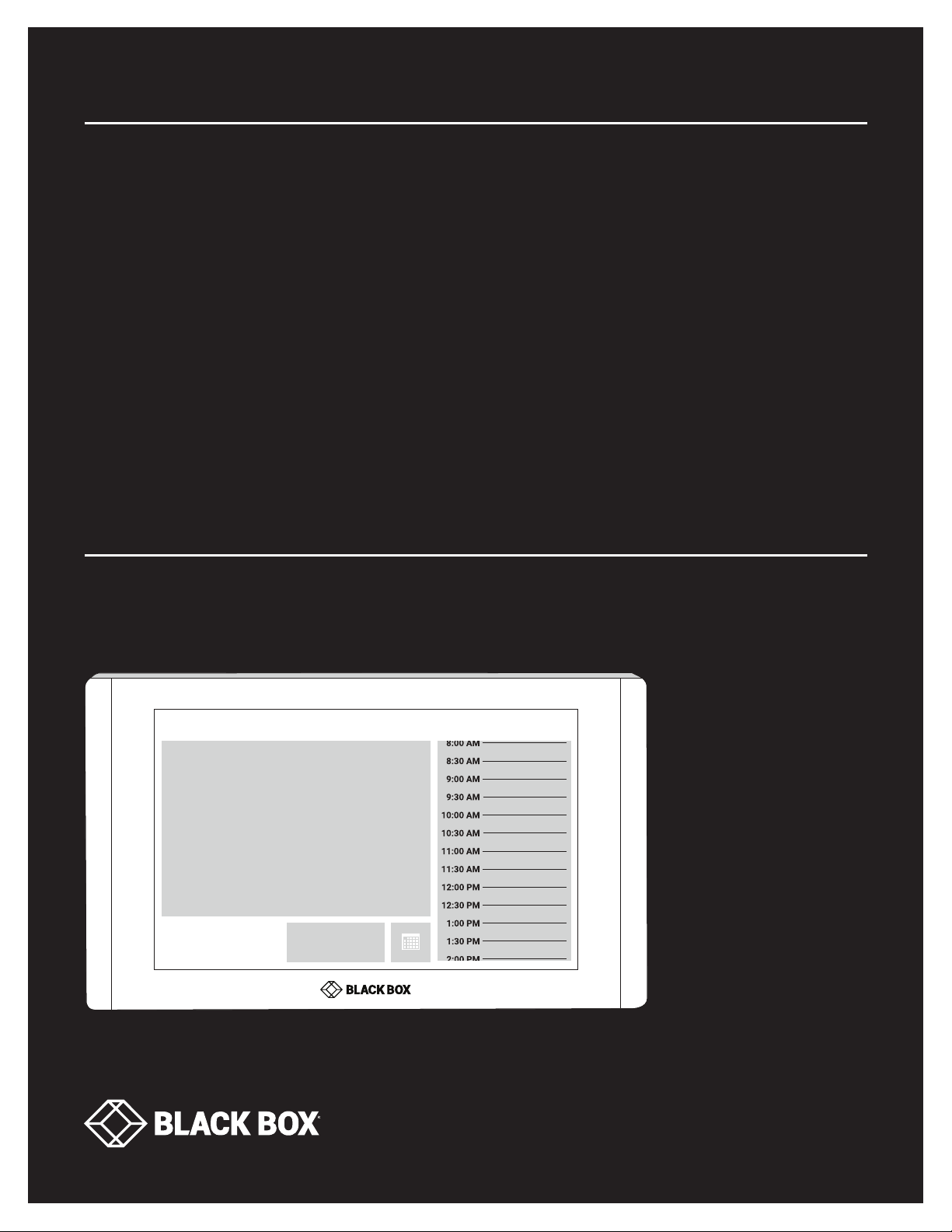
USER MANUAL
RS-TOUCH SERIES
IN-SESSION
ROOM
SCHEDULER
24/7 TECHNICAL SUPPORT AT 1.877.877.2269 OR VISIT BLACKBOX.CO M
Black Box
Free
10:59 AM
November 30, 2017
Reserve
Page 2
NEED HELP?
LEAV E TH E TEC H TO US
LIVE 24/7
TABLE OF CONTENTS
TECHNICAL
SUPPORT
1. 8 7 7. 8 7 7. 2 2 6 9
1. SPECIFICATIONS ........................................................................................................................................................................... 3
2. INTRODUCTION ............................................................................................................................................................................. 4
2.1 Description ................................................................................................................................................................................................ 4
2.2 Network Infrastructure Requirements ...................................................................................................................................................5
2.3 Settings ..................................................................................................................................................................................................... 6
3. ROOM SCHEDULER PANELS CONFIGURATION ......................................................................................................................... 7
3.1 Settings After the First Switching of the Panel ......................................................................................................................................7
3.2 Change of Panel Settings ........................................................................................................................................................................ 8
3.3 Detailed Panel Settings ...........................................................................................................................................................................9
3.4 Setting Up the Room Support Services ................................................................................................................................................14
3.5 Setting Up Control System Integration ................................................................................................................................................ 18
3.6 Using the Room Support Services ........................................................................................................................................................21
3.7 IP Settings ...............................................................................................................................................................................................25
3.8 Firmware Update .................................................................................................................................................................................... 28
4. CONFIGUR ATIO N THROU GH A DMIN WE B................................................................................................................................ 30
4.1 Accessing Admin Web ...........................................................................................................................................................................30
4.2 Login ........................................................................................................................................................................................................31
4.3 Inserting the Company Logo .................................................................................................................................................................31
4.4 Firmware Update .................................................................................................................................................................................... 32
4.5 IP Settings Using Admin Web ...............................................................................................................................................................33
4.6 Other Settings Available in Admin Web ................................................................................................................................................35
5. TECHNICAL SUPPORT ................................................................................................................................................................ 38
5.1 Contacting Black Box .............................................................................................................................................................................38
5.2 Shipping and Packaging ........................................................................................................................................................................38
APPENDIX A. REGULATORY INFORMATION ................................................................................................................................ 39
A.1 FCC Statement .......................................................................................................................................................................................39
A.2 NOM Statement .....................................................................................................................................................................................40
APPENDIX B. DISCLAIMER/TRADEMARKS ................................................................................................................................. 41
B.1 Disclaimer ............................................................................................................................................................................................... 41
B.2 Trademarks Used in this Manual ............................................................................................................ ..............................................41
2
1. 87 7. 8 7 7. 2 26 9 BLACK BOX .COM
Page 3
CHAPTER 1: SPECIFICATIONS
SPECIFICATIONS: IN-SESSION ROOM SCHEDULERS
Connectors (1) RJ-45
Display Type Color a-Si TFT LCD, LED backlit
Display Size RS -TOUCH 7-W, RS -TOUC H7- M:
7" Diagonal;
RS -TOUCH12-W, R S -TOUC H12- M:
12" Diagonal
Resolution 1280 x 800 p
Viewing Angle ±80 degrees horizontal and vertical
Touch
Technology
Sensors Light, proximity
Indicators LEDs: green for free, red for occupied
Interface Wired 10/10 0BaseT Ethernet
Power IEEE 802.3af PoE; 100-240 VAC, 50/60 Hz
Enclosure IP30, aluminum; Edge-to-edge front glass
Installation Fits standard electrical wall boxes
Mounting
Type
Dimensions RS-TOUCH7-W: 4.7"H x 7.8"W x 1.5"D (12 x 19.9 x 3.9 cm);
Weight RS-TOUCH7-W: 1.3 lb. (0.6 kg);
Projected capacitive
RS -TOUCH7-W, RS -TOUCH12-W: In-Wall;
RS -TOUCH7- M, RS -TOUCH12-M: On-Wall
RS-TOUCH7-M: 4.7"H x 7.8"W x 1.1"D (12 x 19.9 x 2.6 cm);
RS-TOUCH12-W: 7.8"H x 12.5"W x 1.8"D (20 x 32 x 4.7 cm);
RS-TOUCH12-M: 7.8"H x 12.5"W x 1.3"D (20 x 32 x 3.3 cm)
RS-TOUCH12-W: 4.4 lb. (2 kg);
RS-TOUCH7-M: 1.6 lb. (0.8 kg);
RS-TOUCH12-M: 4.8 lb. (2.2 kg)
NEED HELP?
LEAV E TH E TEC H TO US
LIVE 24/7
TECHNICAL
SUPPORT
1. 8 7 7. 8 7 7. 2 2 6 9
Comparison Chart:
Part Number Mounting Type Installlation Display Size Dis p lay Type Resolution
RS-TOUCH7-W In-Wall Fits standard electrical wall box 7" diagonal Color a-Si TFT LCD,
1280 x 800 p
LED backlit
RS-TOUCH7-M On-Wall Fits standard electrical wall box 7" diagonal Color a-Si TFT LCD,
1280 x 800 p
LED backlit
RS-TOUCH12-W In-Wall Fits standard electrical wall box 12" diagonal Color a-Si TFT LCD,
1280 x 800 p
LED backlit
RS-TOUCH12-M On-Wall Fits standard electrical wall box 12" diagonal Color a-Si TFT LCD,
1280 x 800 p
LED backlit
1. 87 7. 8 7 7. 2 26 9 BLACK BOX .COM
3
Page 4

NEED HELP?
LEAV E TH E TEC H TO US
LIVE 24/7
CHAPTER 2: INTRODUCTION
2.1 DESCRIPTION
IN-SESSION is a meeting room reservation system. The IN-SESSION system touch panels are installed in front of the entrance to
the room and show its state.
The panels have the following functions:
Show whether the particular room is occupied or available, which is also indicated by background color (green for a free room and
red for an occupied one).
If the room is free, the panel shows the subsequent meeting on that day (in case it is scheduled) and the time remaining until its
beginning.
If the room is occupied, the panel shows the subject of the meeting, the organizer and time remaining until its end.
The panel enables the user to browse the calendar of the room and view the details of scheduled meetings.
It is possible to reserve the room for the next available time in the calendar.
If a meeting is in progress, it is possible to extend it or finish it (unless another even is scheduled afterwards).
The IN-SESSION Room Scheduler system panels are available in two different sizes: 7" and 12". The IN-SESSION system
cooperates with the following servers or services where the room calendars are saved:
Microsoft Exchange Server 2007, 2010, 2013, 2016.
Microsoft Office 365 subscription (any Business, Education, Enterprise or Government plan with support of resource/room
mailboxes; home and personal plans are not supported).
G Suite, formerly Google Apps for Work, subscription (Google Apps Free edition, also known as Standard edition, is not supported).
It is also possible to use the default applications of these services to make a reservation of a room (Outlook, web interface, mobile
applications).
For easy administration of reservation system units, these units are linked to a group called reservation suite. Units connected to
the same reservation suite share their settings so, for example, if you need to change the user account password, you can just do it
on one panel and all the other ones within the same reservation suite will adopt the change automatically. The reservation suite can
be managed in the following ways:
Essential Setup: In this administration mode, you change the settings on any reservation suite unit, and settings shared within the
Reservation Suite will be automatically applied to all units. Other settings (individual settings of each unit, e.g. language, display
brightness, etc.) must be done on each unit separately. All reservation system units included in the Reservation Suite must be
plugged into the same LAN. This guide describes the management of the reservation system through Essential Setup.
On-premises Administration: In this way, the entire reservation suite is centrally managed through the web interface of the IN-
SESSION RS-MODERATOR unit. The IN-SESSION RS-MODERATOR must be plugged into the same LAN as the other units of the
Reservation Suite. IN-SESSION RS-MODERATOR also has other features, such as analytics and room utilization statistics. The
procedure for setup using On-premises Administration is described in the IN-SESSION RS-MODERATOR user manual.
TECHNICAL
SUPPORT
1. 8 7 7. 8 7 7. 2 2 6 9
4
1. 87 7. 8 7 7. 2 26 9 BLACK BOX .COM
Page 5

NEED HELP?
LEAV E TH E TEC H TO US
LIVE 24/7
CHAPTER 2: INTRODUCTION
TECHNICAL
SUPPORT
1. 8 7 7. 8 7 7. 2 2 6 9
2.2 NETWORK INFRASTRUCTURE REQUIREMENTS
For the proper functioning of the system, ensure the following:
Server access (Exchange Server, Office 365, G Suite) via HTTP (TCP port 80) and HTTPS (TCP port 443).
NTP (Network Time Protocol) servers access (UDP port 123).
Functional DNS servers.
Correctly set time zones for all required accounts (i.e. rooms).
An open TCP port 80 (HTTP) and 443 (HTTPS) within the local network for the administration of IN-SESSION Room Scheduler units
by means of Admin Web.
An open TCP port 53128 and UDP port 33333 within the local network for communication between IN-SESSION Room Scheduler
units. Communication between units is encrypted using AES-256.
An open UDP port 53 for communication with DNS server and for conversion of domain names to IP addresses.
An open UDP ports 67 and 68 for communication with DHCP server and for IP address assignment, if DHCP is used.
An open UDP port 1900. Opening this port is not mandatory, it is used to make the reservation system units visible in the Windows
File Explorer. This port uses UPnP technology (Universal Plug and Play), thanks to which reservation system units in the file explorer
can be made visible as other network devices. This technology must also be enabled on a given computer.
An open proxy server port if a proxy server is used to access HTTPS servers.
Access the server my.cuesystem.com over HTTPS (TCP port 443). This access is not mandatory, it is used to update the firmware.
Free LAN sockets on Ethernet switches for IN-SESSION Room Scheduler units.
CAT5 or higher LAN cables leading from an Ethernet switch to the place where you want to install IN-SESSION Room Scheduler
units.
All reservation system units included in the Reservation Suite must be plugged into the same LAN.
The use of PoE (Power over Ethernet) of the Ethernet switches is recommended as it will simplify the necessary cabling. In case
your switches do not support the PoE technology, use the enclosed PoE injectors and connect them between the Ethernet switch
and the IN-SESSION Room Scheduler panel.
The network card of IN-SESSION Room Scheduler panels supports speeds up to 100 Mbit/s. If you are using a faster LAN, set up
ports intended for IN-SESSION panels on your switch to auto negotiate or to 100 Mbit/s.
IN-SESSION supports the following cryptographic standards for HTTPS access: SSL 3.0, TLS 1.0, TLS 1.1, TLS 1.2. Supported
encrypting includes 3DES, AES-128 and AES-256.
IN-SESSION panels are connected to LAN using a single cable, which also provides power via PoE (Power over Ethernet)
technology.
TABLE 1-1. POE STANDARDS BY PRODUCT CODE
PRODU CT C ODE POE STANDARD CLASS
RS-TOUCH7-M, RS-TOUCH7-W IEEE 802.3af Class 0
RS-TOUCH12-M, RS-TOUCH12-W IEEE 802.3at Class 4
Check that no security programs or functions (such as firewalls, proxy servers, domains etc.) block straight HTTP/HTTPS
communication between the IN-SESSION units and servers with room calendars.
1. 87 7. 8 7 7. 2 26 9 BLACK BOX .COM
5
Page 6

NEED HELP?
LEAV E TH E TEC H TO US
LIVE 24/7
CHAPTER 2: INTRODUCTION
2.3 SET TINGS
This document describes such settings of the reservation system using Essential Setup that are common for all types of supported
servers. The procedure for setting up specific types of servers is described in the following documents.
IN-SESSION - Setup Guide - Microsoft Exchange Server
IN-SESSION - Setup Guide - Microsoft Office 365
IN-SESSION - Setup Guide - G Suite
To set the IN-SESSION system, you need to:
1. Prepare accounts on the specific server using the guides above.
2. Configure the IN-SESSION Room Scheduler panels using the guides above as well as the following chapters.
TECHNICAL
SUPPORT
1. 8 7 7. 8 7 7. 2 2 6 9
6
1. 87 7. 8 7 7. 2 26 9 BLACK BOX .COM
Page 7
CHAPTER 3: ROOM SCHEDULER PANELS CONFIGURATION
3.1 SETTINGS AFTER THE FIRST SWITCHING OF THE PANEL
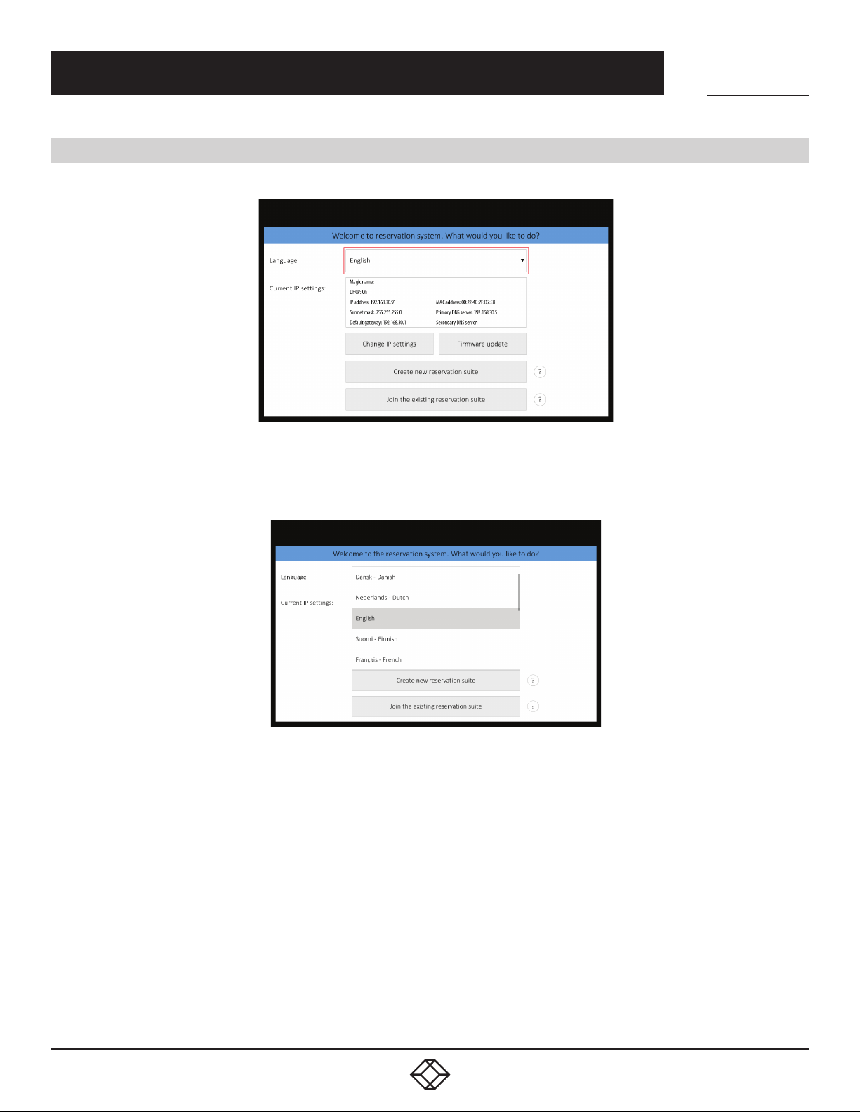
After the IN-SESSION Room Scheduler panel is switched for the first time, the following screen will appear on it:
NEED HELP?
LEAV E TH E TEC H TO US
LIVE 24/7
TECHNICAL
SUPPORT
1. 8 7 7. 8 7 7. 2 2 6 9
FIGURE 3-1. INITIAL SCREEN
You can change the user interface language of the panel in “Language.” Touch the red-marked field and a list of available
languages appears. Choose your preferred language.
FIGURE 3-2. LANGUAGE SCREEN
In the default setting, the panel is enabled to obtain the IP address and DNS servers using your network’s DHCP. Under the item
“Current IP settings” you can check whether the assigned addresses correspond with your network. If this setting does not meet your
requirements, you can change it according to the instructions in the chapter IP settings.
Units connected to the same reservation suite share their settings, e.g. if you need to change the user account password, you can just
do it on one panel and all the other ones within the same reservation suite will adopt the change automatically. The reservation suite
name and password serve for mutual identification of panels. The password is also used for accessing the panels’ settings.
Now you can create a new reservation suite just by tapping on “Create new reservation suite” or you can join the panel to the existing
reservation suite by tapping “Join to existing reservation suite“. The following settings vary depending on the type of server. Follow the
steps in the Chapter IN-SESSION panels configuration in guides dedicated to specific server type:
IN-SESSION - Setup Guide - Microsoft Exchange Server
IN-SESSION - Setup Guide - Microsoft Office 365
IN-SESSION - Setup Guide - G Suite
1. 87 7. 8 7 7. 2 26 9 BLACK BOX .COM
7
Page 8
NEED HELP?
LEAV E TH E TEC H TO US
LIVE 24/7
CHAPTER 3: ROOM SCHEDULER PANELS CONFIGURATION
3.2 CHANGE OF PANEL SETTINGS
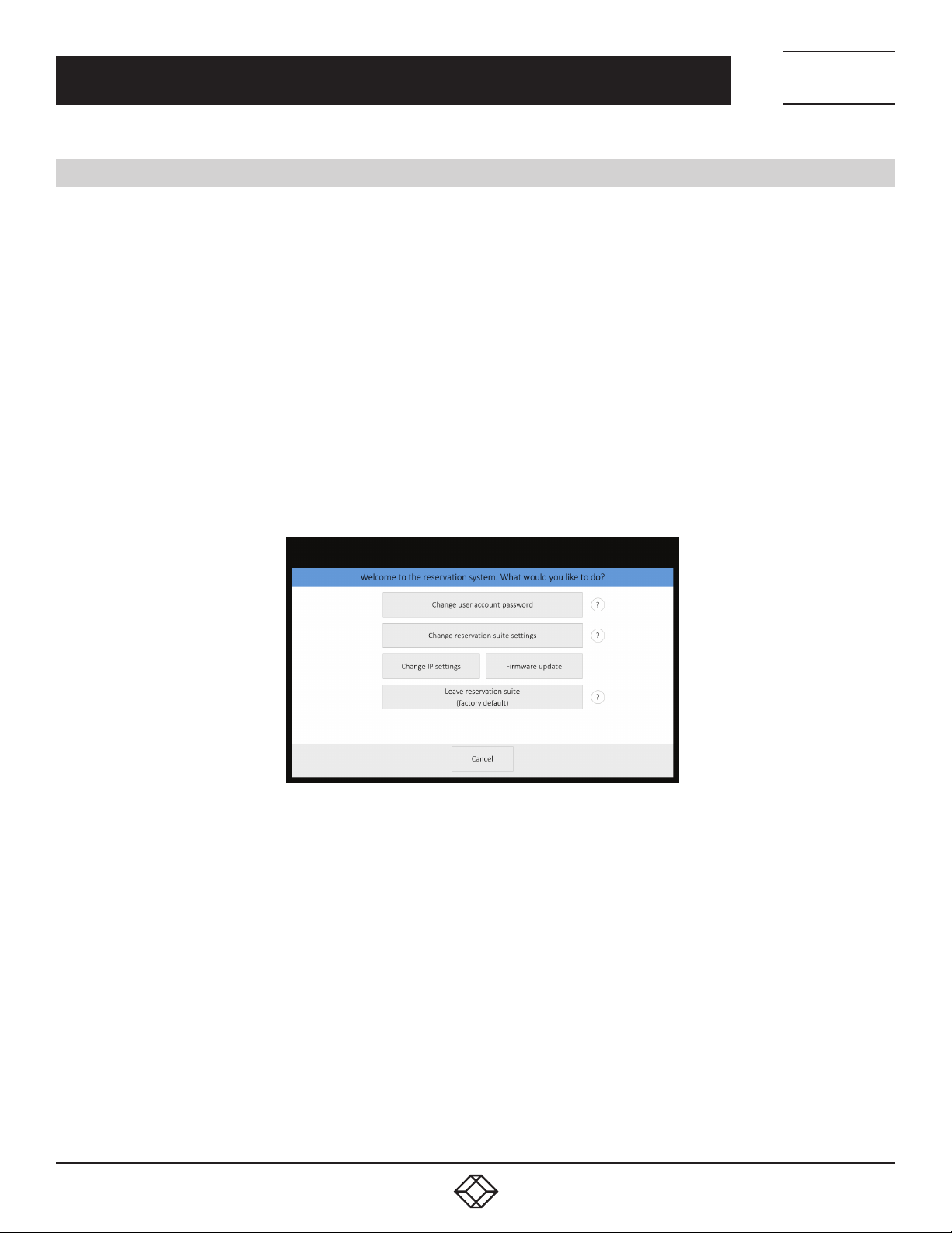
In case you need to change the configuration of a panel that is already set, connected to the reservation suite and in normal
operation, tap and hold the upper left corner (where the room name is) for about 5 seconds until keyboard appears along with
“Enter password” notice. Enter the password you have chosen during the creation of the reservation suite.
On the next screen, you can do the following:
“Change user account password“. Here you can change password for user accounts used with Microsoft Office 365 or Microsoft
Exchange Server. This option is not available for G Suite server.
“Change IP settings“. You can find more details in the chapter IP settings.
“Change reservation suite settings“. Here you can change accounts and detailed panel settings - see the text below.
“Leave reservation suite (factory default)“. With this option, you can delete all user panel settings and restore the panel factory
settings.
“Firmware update”.
Choose “Change reservation suite settings” on the this screen. Tapping “Next” will take you step-by-step through the settings
screens (“Server settings – User account settings – Room settings”) and then you get to detailed settings screens.
TECHNICAL
SUPPORT
1. 8 7 7. 8 7 7. 2 2 6 9
FIGURE 3-3. CHANGE PANEL SETTINGS SCREEN
8
1. 87 7. 8 7 7. 2 26 9 BLACK BOX .COM
Page 9
CHAPTER 3: ROOM SCHEDULER PANELS CONFIGURATION
3.3 DETAILED PANEL SETTINGS
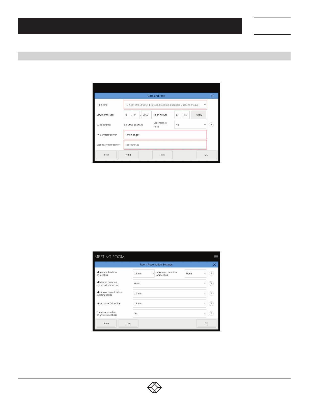
The first of the detailed panel settings pages relates to setting time and date.
NEED HELP?
LEAV E TH E TEC H TO US
LIVE 24/7
TECHNICAL
SUPPORT
1. 8 7 7. 8 7 7. 2 2 6 9
FIGURE 3-4. SET TIME AND DATE SCREEN
You can choose your time zone here and the panel will automatically change summer and winter time according to the rules in the
specific zone.
Setting the time correctly is essential for the correct operation of the reservation panel. The panel enables synchronizing its clock
with internet time (NTP) servers. This function is enabled in the default setting and we recommend keeping it that way (“Use
internet clock” item is set to “Yes”). Time (NTP) servers are pre-set to “time.nist.gov” and “tak.cesnet.cz” but if it does not suit you,
you can change it to any NTP servers you prefer by tapping the relevant field. The “Next” button will take you to reservation system
behavior settings screen.
Settings on this screen are shared by all units within the same reservation suite. It means that whatever you change here will be
adopted by all the panels.
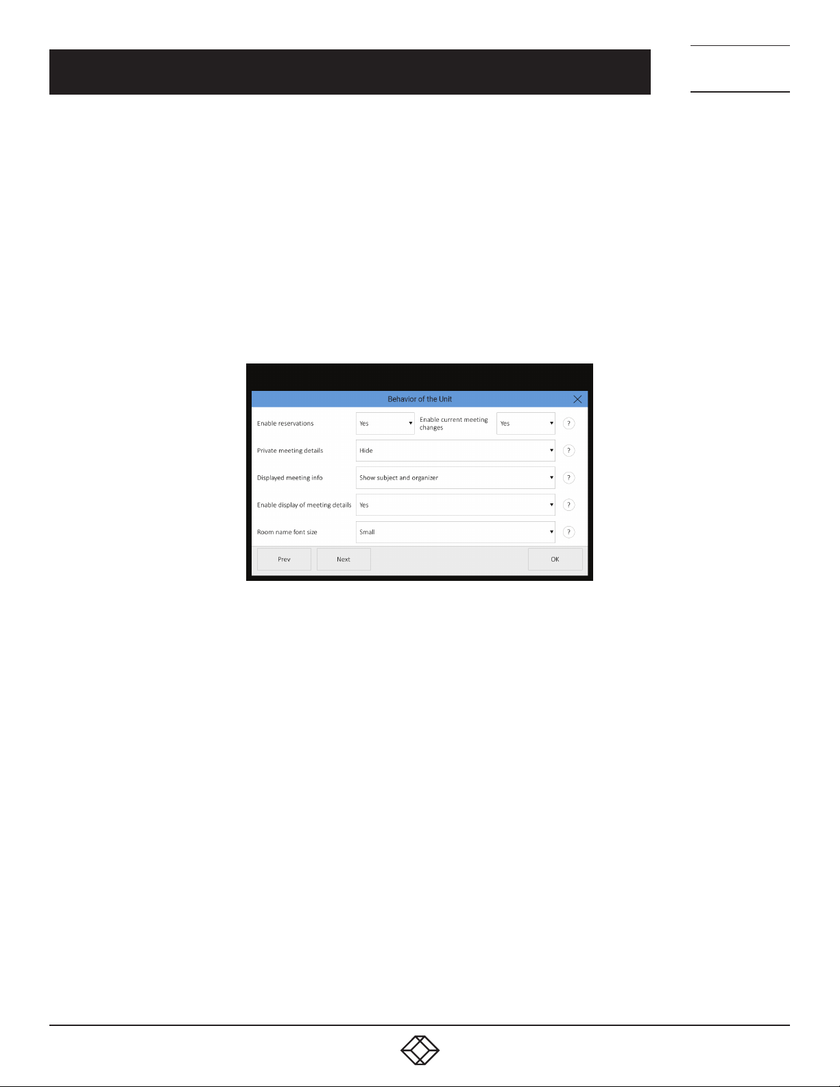
FIGURE 3-5. RESERVATION SYSTEM SETTINGS SCREEN
The items “Minimum duration of meeting” and “Maximum duration of meeting” allow you to set the limits for reservations made
through a panel. The maximum duration is limited to midnight of the given day. Default setting for the minimum time is 15 minutes
and “None” for the maximum time. The item “Maximum duration of extended meeting” allows you to limit the maximum length of
meeting extended by means of the panel. The default value is “None,” lasting until the end of the day at maximum.
1. 87 7. 8 7 7. 2 26 9 BLACK BOX .COM
9
Page 10
NEED HELP?
LEAV E TH E TEC H TO US
LIVE 24/7
CHAPTER 3: ROOM SCHEDULER PANELS CONFIGURATION
The “Mark as occupied before meeting starts” item allows you to set the time before the scheduled beginning of the meeting when
the room will be marked red—i.e., occupied. For example, if this item is set to 10 minutes (as is the default setting) and the actual
beginning of the meeting is at 10:00, the room will be marked as occupied from 09:50.
The “Mask server failure for” item enables you to set the time for which there will be no error message shown on the panel in case
of loss of communication with the server. It means that if the loss of communication period is shorter than the set time, no error
message will be shown on the panel. In the course of such loss, the panel may not display up-to-date information. The default setting
is 15 minutes.
The “Enable reservation of private meetings” item enables you to set whether the option of labeling a new meeting as private is
allowed when booking a new meeting. The default value is “Yes”.
On the following screens you can set the behavior of individual panels, i.e., a change on one panel does not affect other panels..
TECHNICAL
SUPPORT
1. 8 7 7. 8 7 7. 2 2 6 9
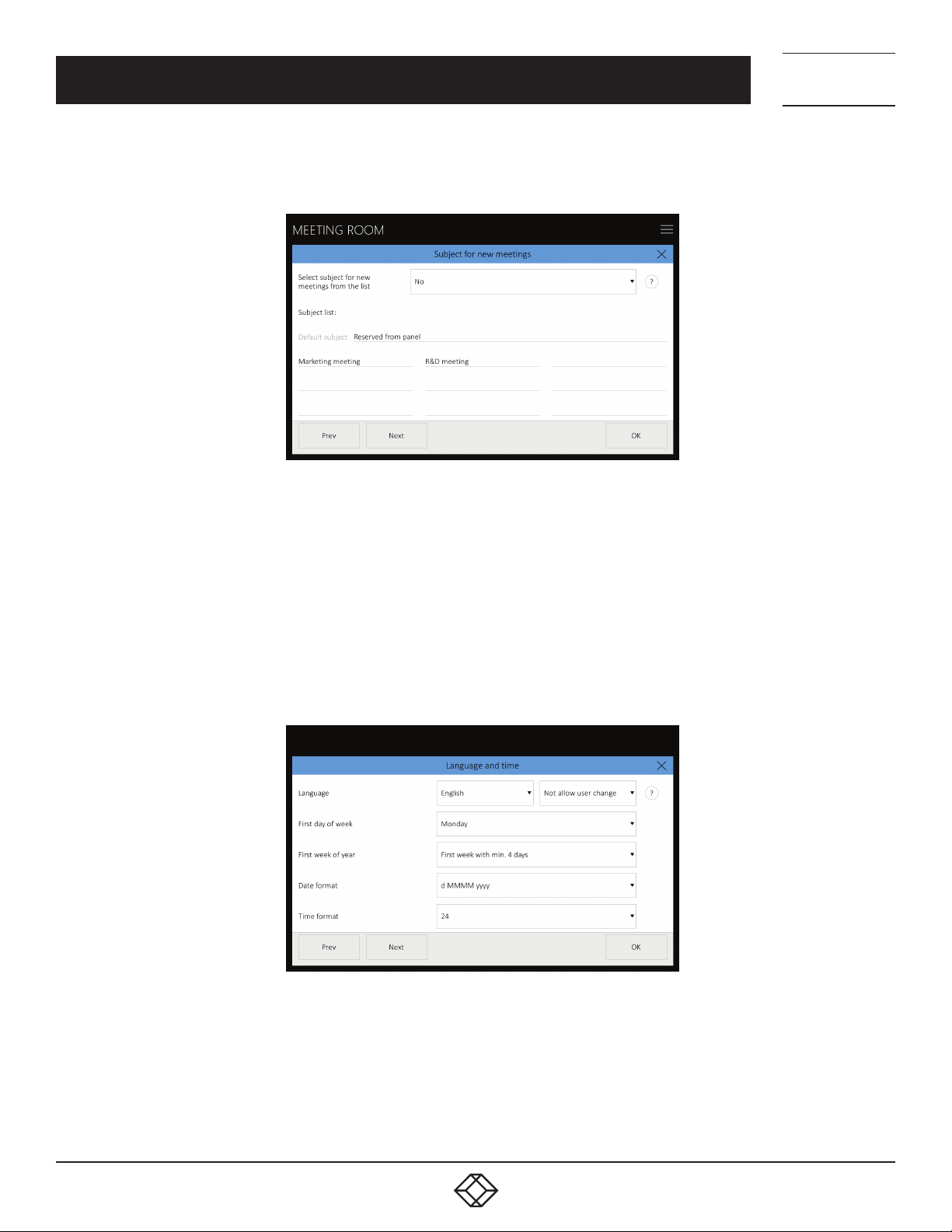
FIGURE 3-6. SET INDIVIDUAL PANELS
The “Enable reservations” item allows you to set whether or not room reservations can be made from the specific panel (if not,
the“Reserve” button is hidden). The default setting is “Yes.”
The “Enable current meeting changes” item allows you to set whether or not it is possible to extend or finish the current meeting
(ifnot, the “Extend” and “Finish” buttons are hidden). The default setting is “Yes.”
Scheduled meetings can be labeled as private. The “Private meetings details” item allows you to set whether on the panel you will see
the full description and details of meetings labeled like that (option “Show”) or just “Private meeting” label (option “Hide”). You can
also choose “Hide except current meetings”. In this case details will be shown only for the current or upcoming private meeting and
details of other meetings will be hidden. The default setting is “Hide”.
Under “Displayed meeting info”, you can set how meeting information is displayed on the panel. You can choose to view both the
subject and the organizer, only the subject or only the organizer. The default option is to display both the subject and the organizer. If
you press the appointment in the calendar, a meeting details window will be displayed including subject and organizer (if the meeting
is not private). You can disable the meeting details display in this way using the “Enable display of meeting details” option.
Under “Enable display of meeting details,” you can enable or disable the display of the meeting details window by tapping the
appointment in calendar. The Meeting details window displays the appointment details including subject and organizer. If you want to
view the details of meetings in this way, select “Yes,” otherwise, select “No.” The default is “Yes.”
NOTE: Private meetings information is displayed according to the option “Private meetings details.”
The “Room name font size” item allows you to set the font size of the room name in the upper left corner of the panel. The default
setting is “Small.”
10
1. 87 7. 8 7 7. 2 26 9 BLACK BOX .COM
Page 11
CHAPTER 3: ROOM SCHEDULER PANELS CONFIGURATION
On the following screen, you can set how the meeting subject will be entered when a new meeting is created.
FIGURE 3-7. ENTER MEETING SUBJECT SCREEN
NEED HELP?
LEAV E TH E TEC H TO US
LIVE 24/7
TECHNICAL
SUPPORT
1. 8 7 7. 8 7 7. 2 2 6 9
While creating a new meeting, you need to enter the subject of the meeting. Under “Select subject for new meetings from the list,”
you can select whether the subject of the meeting is selected from the list set on this page (option “Yes”) or whether the user will
type it using the keyboard (option “No”). The default setting is “No.” In the “Subject list,” fill up to ten possible meeting subjects. The
first item on the list is the default subject of the meeting. This one is used even when the subject is entered using the keyboard. If
you select a keyboard entry and the default meeting subject is not filled in here, you will always need to enter the subject using the
keyboard when booking a room.
Settings on this screen are shared by all units within the same reservation suite. It means that whatever you change here will be
adopted by all the panels.
The setting on the next screen is individual for each panel.
FIGURE 3-8. INDIVIDUAL PANEL SETTING
The “Language” item allows you to set the language of the panel’s user interface. Here you can also enable common users to
change the language on the panel. If this is enabled, the options menu button will appear in the upper right corner and the user can
change the language on the panel. Available options include changing panel language for 2 minutes, until the end of the current
meeting or until the end of the day.
The “First day of week” and “First week of year” items determine the way monthly calendar will be displayed—i.e., which day of the
week is displayed as the first and how weeks are numbered. The default setting is “Monday” and “First week with min. 4 days.”
1. 87 7. 8 7 7. 2 26 9 BLACK BOX .COM
11
Page 12
NEED HELP?
LEAV E TH E TEC H TO US
LIVE 24/7
CHAPTER 3: ROOM SCHEDULER PANELS CONFIGURATION
In “Date format,” choose whether you want the date shown in “d MMMM yyyy” format (for example, “26 February 2016”) or in “MMMM
d yyyy” format (for example, “February 26, 2016”). The default setting is “d MMMM yyyy”.
In “Time format,” choose whether you want the time shown in 24-hour or 12-hour (12 AM/PM) format. The default setting is “24”.
Panel display settings can be adjusted on the next screen. This setting is also individual for each display.
TECHNICAL
SUPPORT
1. 8 7 7. 8 7 7. 2 2 6 9
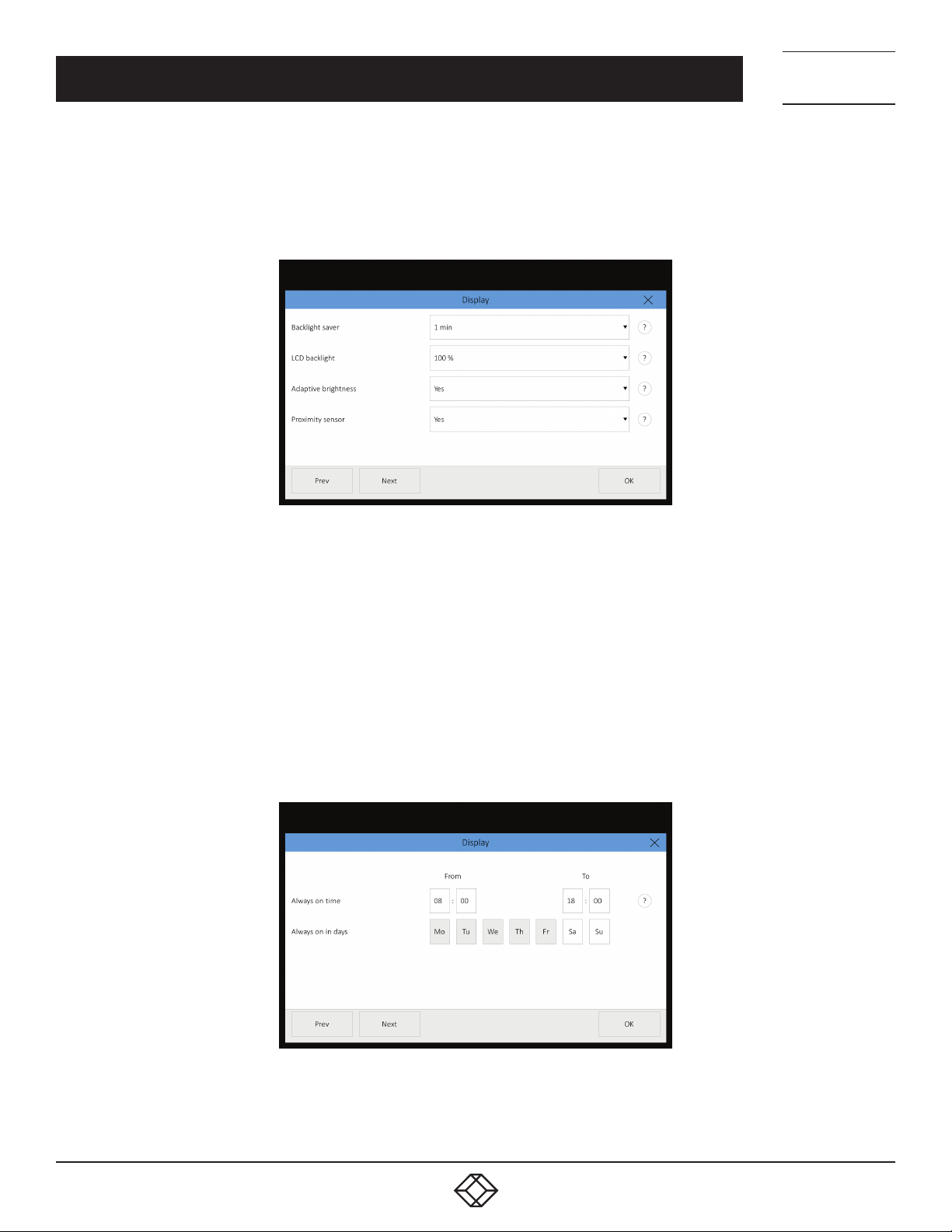
FIGURE 3-9. DISPLAY SETTINGS
In “Backlight saver,” you can set after how long the display illumination is turned off in case of panel inactivity. The default setting is
“1 min”.
The “LCD backlight” item allows you to set the brightness of the display from 0% to 100%. The default setting is “70%”.
In “Adaptive brightness,” you can set whether or not the brightness of the display is regulated depending on the surrounding lighting.
The default setting is “No”.
The “Proximity sensor” item allows you to set whether the display will be woken from screen-saving mode automatically using the
sensor (option “Yes”) or manually by touching the screen (option “No”). The default setting is “Yes”.
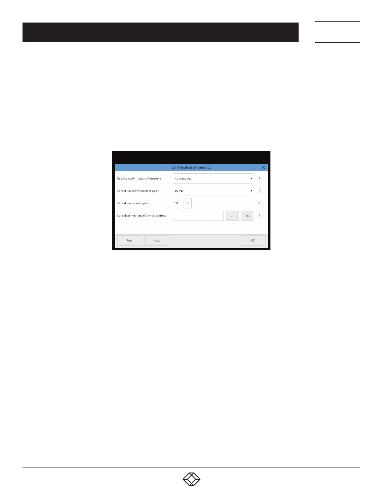
The next screen allows you to set times and days when the panel will be constantly switched on. The screensaver will, therefore, not
be active during those periods of time. These periods of time are usually set for your ordinary working hours when the panels are
constantly switched on; at other times, screensaver is used.
12
FIGURE 3-10. SET TIME AND DAYS WHEN SCREEN IS ON
1. 87 7. 8 7 7. 2 26 9 BLACK BOX .COM
Page 13
NEED HELP?
LEAV E TH E TEC H TO US
LIVE 24/7
CHAPTER 3: ROOM SCHEDULER PANELS CONFIGURATION
Here you can set the time (“Always on time”), from when (“From”) until when (“To”), the panel will be constantly switched on. Use the
buttons “Always on in days” to set the days when the panel will be switched on at given times. The default setting is that the panel is
switched on from 08:00 to 18:00 from Monday to Friday.
On the following screens, you can set meeting confirmation. Meeting confirmation is a function of the reservation system that
makes it mandatory to confirm a previously planned meeting. Confirmation is possible through a dialog box on the panel, using
information from occupancy sensors (detection of the presence of people in the room), or a combination of both. When combining
both confirmation modes, the meeting is confirmed by whichever of the two events occurs first (either the presence of persons in the
room or confirmation by a dialog box on the panel). If it is not confirmed that the meeting will take place, the meeting is automatically
cancelled. Five minutes before cancelling the meeting, the system sends an email to the user reminding them to confirm the meeting
on the panel. This setting is individual for each room.
TECHNICAL
SUPPORT
1. 8 7 7. 8 7 7. 2 2 6 9
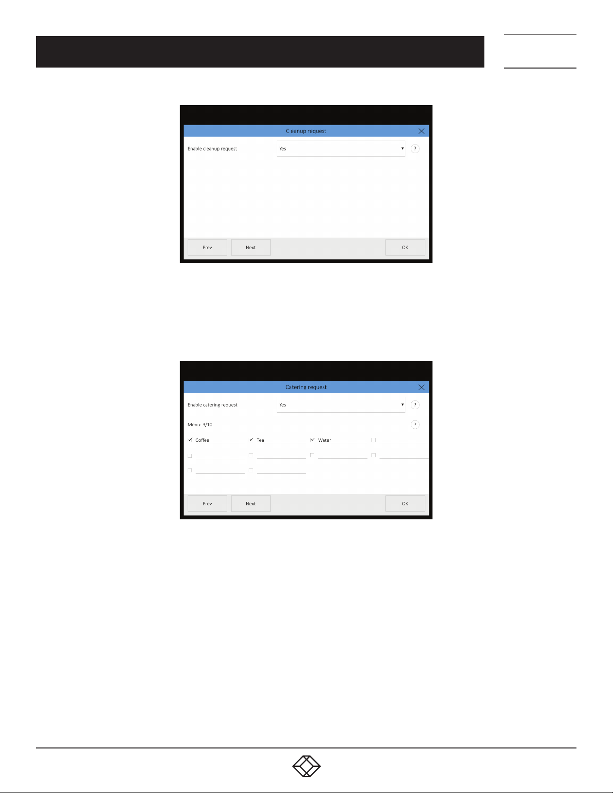
FIGURE 3-11. MEETING CONFIRMATION SCREEN
In the item “Require confirmation of meetings,“ activate the function by selecting “By dialogue box on the panel,“ “By occupancy
sensors” or “By occupancy sensors or dialog box.” If you do not require confirmation, choose “Not required.” The default setting is
“Not Required.”
Meetings fall into two categories according to duration:
Common meeting is a meeting taking place within a limited period of time during one day:
Example: A meeting from 10:00 AM to 3:00 PM
A long meeting—this category includes all-day meetings, meetings that last more than one day or unusually long meetings. These are
characterized by the following criteria:
- They begin at 12:00 AM of the current day or earlier
- They end after the time set for cancelling long meetings of the current day
Example 1: The meeting starts at 12:00 AM of the previous day and ends at 12:00 AM of the following day
Example 2: The meeting starts at 12:00 AM of the current day and ends at 2:00 PM of the current day (the time of canceling a long
meeting has been set to 9:15 AM in this example)
In the item “Cancel unconfirmed meeting in” set the period of time after the beginning of the current meeting at which the meeting,
unless confirmed, will be cancelled.
Example: the period of time for the cancellation of a common meeting is set to 15 min. The meeting starts at 10:30 AM. If the meeting
is not confirmed on the panel by this time, the organizer of the meeting gets an email at 10:40 AM with awarning about cancellation.
If the meeting is not confirmed by 10:45 AM, it will automatically be cancelled at 10:45 AM.
1. 87 7. 8 7 7. 2 26 9 BLACK BOX .COM
13
Page 14

NEED HELP?
LEAV E TH E TEC H TO US
LIVE 24/7
CHAPTER 3: ROOM SCHEDULER PANELS CONFIGURATION
In the item “Cancel long meetings at” set the time of the day (i.e. from midnight on) by which long meetings have to be confirmed.
Example 1: The meeting starts at 10:00 AM on the previous day and ends at 11:59 PM on the current day. The time of canceling long
meetings is set to 8:20 AM. If the meeting is not confirmed, the organizer gets an email at 8:15 AM. If the meeting is not confirmed
by 8:20 AM of the current day, it will automatically be canceled at 8:20 AM.
Example 2: The meeting lasts from 12:00 AM of the current day to 10:00 PM of the following day. The time for the cancellation of
long meetings is set to 9:15 AM. The organizer gets an email at 9:10 AM. If the meeting is not confirmed by 9:15 AM of the current
day, the beginning of the meeting is at this moment shifted to 12:00 AM of the following day (see below for exceptions).
Exceptions—meeting confirmation has the following exceptions:
If you reserve a room from the panel and the meeting starts within 15 min from the moment of the reservation, the meeting does
not need to be confirmed (it is considered confirmed).
Meetings that last several days must be confirmed every day.
Meetings that end later than the current day do not get cancelled, but their beginning is shifted to 12:00 AM of the following day, i.e.
the room is made free only for the current day.
In the field “Canceled meeting info email address,” you can enter an email address for receiving information about automatically
cancelled meetings that have not been confirmed on the reservation system panel. You can send a testing email by pressing “Test.”
Configuration can be ended and saved by pressing “OK,” or you can proceed to set up room support services.
TECHNICAL
SUPPORT
1. 8 7 7. 8 7 7. 2 2 6 9
3.4 SETTING UP THE ROOM SUPPORT SERVICES
Reservation system panels enable sending of room support requests. Through the panels you can:
Order room cleanup.
Order catering.
Send a request for repair to two various service departments. One of these, for example, may be the facility service department
(dealing with malfunction of air-conditioning, lighting, ventilation etc.) and the other one the IT department (caring for the
functionality of computers, Wi-Fi connection, LAN and do on).
If some of these reservation panel functions are enabled, you will see an options button in the upper right corner of the panel. From
there you can send requests for room support, order catering, etc. Requests are sent to the email address you have entered for this
purpose (see the page “Room support emails”). If cleanup or support request is sent through the panel, an icon in the upper right
corner indicates that the room is waiting for cleanup or repair. For more detailed description of how to use the services, see the
chapter Using the room support services.
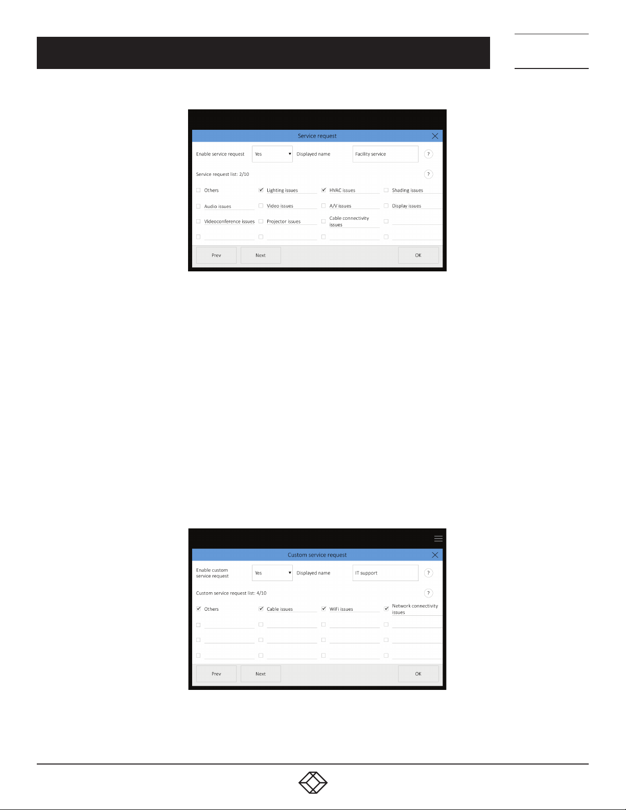
On the “Cleanup request“ page in the item “Enable cleanup request,“ you can enable the function of ordering cleanup through the
reservation system panel. This setup is individual for each panel of the reservation suite, i.e., cleanup requests may be enabled on
some panels while on others this function may be disabled.
14
1. 87 7. 8 7 7. 2 26 9 BLACK BOX .COM
Page 15
NEED HELP?
LEAV E TH E TEC H TO US
LIVE 24/7
CHAPTER 3: ROOM SCHEDULER PANELS CONFIGURATION
FIGURE 3-12. CLEANUP REQUEST SCREEN
On the “Catering request“ page in the item “Enable catering request,“ you can enable the function of ordering refreshments through
the reservation system panel. This setup is individual for each panel of the reservation suite, i.e., catering requests may be enabled on
some panels while on others this function may be disabled.
TECHNICAL
SUPPORT
1. 8 7 7. 8 7 7. 2 2 6 9
FIGURE 3-13. CATERING REQUEST SCREEN
In the “Menu“ section you can enter catering requests. You can edit them by clicking on respective items. You can enable or disable
an item by using the checkbox to the left of the item (you can for instance disable an item if it is temporarily unavailable). In such
case, you do not need to delete the whole item, but you can enable or disable it by using the checkbox. There can be amaximum of
10 items on the menu. The menu is shared by the whole reservation suite, i.e., when you change it on one panel, the changes will be
effective on all the remaining panels of the reservation suite as well.
On the “Service request“ page in the item “Enable service request,“ you can enable the function of ordering technical support through
the reservation system panel. This setup is individual for each panel of the reservation suite, i.e., technical support requests may be
enabled on some panels while on others this function may be disabled. Settings on this page relate to the first of the two possible
support/service departments.
1. 87 7. 8 7 7. 2 26 9 BLACK BOX .COM
15
Page 16
NEED HELP?
LEAV E TH E TEC H TO US
LIVE 24/7
CHAPTER 3: ROOM SCHEDULER PANELS CONFIGURATION
FIGURE 3-14. SERVICE REQUEST SCREEN
In the “Displayed name“ field, you can edit the name of the service department that will be displayed in the user menu, e.g. “Facility
service.”
In the “Service request list” section, you can edit the list of possible interventions available from the given service department. You
can enter up to 15 items. The list is shared by the whole reservation suite.
By using checkboxes for respective items, you can select which interventions will be available for a given room. For example,
“Air-conditioning issue” is one of the items, but some rooms may not be equipped with air-conditioning. You can therefore use
the checkbox to enable this function only where relevant. For each room, you can select up to 10 items from the list of available
interventions. If you enable the item “Others,” the user will be asked to enter a description of the problem upon sending the request.
The enabled support requests are shared throughout the room account, i.e., if a room has more entrances with a panel assigned to
each, all the panels will display the same offer of possible interventions.
On the “Custom service request“ page in the item “Enable custom service request,“ you can enable the function of ordering
technical support from the other service department (out of two possible ones). This setup is individual for each panel of the
reservation suite, i.e., custom service requests may be enabled on some panels while on others this function may be disabled.
Others settings on the “Custom service request” page are the same as on the previous page “Service request.”
TECHNICAL
SUPPORT
1. 8 7 7. 8 7 7. 2 2 6 9
16
FIGURE 3-15. CUSTOM SERVICE REQUEST SCREEN
1. 87 7. 8 7 7. 2 26 9 BLACK BOX .COM
Page 17
NEED HELP?
LEAV E TH E TEC H TO US
LIVE 24/7
CHAPTER 3: ROOM SCHEDULER PANELS CONFIGURATION
TECHNICAL
SUPPORT
1. 8 7 7. 8 7 7. 2 2 6 9
Other settings on the “Custom service request” page are the same as on the previous page “Service request.”
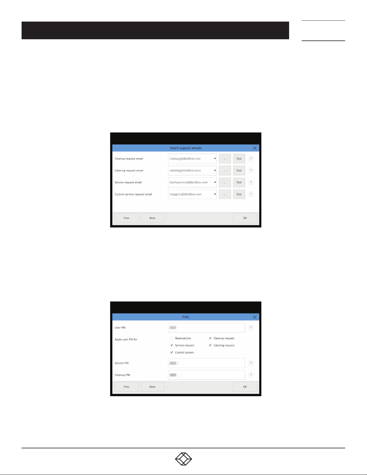
On the next page “Room support emails,“ you can set the email address to which the following requests will be sent:
Cleanup (“Cleanup request email”).
Catering (“Catering request email”).
First service department (“Service request email“).
Second service department (“Custom service request email“).
FIGURE 3-16. ROOM SUPPORT EMAILS SCREEN
You can edit the email address after pressing “…“ You can also select the address from the list of previously entered addresses
by clicking on the drop-down listbox. By pressing “Test,” you can send a testing email to the entered address and thus check its
functionality.
On the “PINs” page, you can set PINs for access to some of the reservation panel functions. PIN is a number comprising 4-6
characters. If you do not wish to use access through PINs, leave the fields with PIN value blank. PINs are shared by the whole
reservation suite.
FIGURE 3-17. PINS SCREEN
1. 87 7. 8 7 7. 2 26 9 BLACK BOX .COM
17
Page 18

NEED HELP?
LEAV E TH E TEC H TO US
LIVE 24/7
CHAPTER 3: ROOM SCHEDULER PANELS CONFIGURATION
User PIN is used to restrict access to some basic functions of the reservation system. For example, it can be used to enable all
employees (who know the user PIN) to access all available functions while visitors (not knowing the user PIN) will be able to
access only those functions that do not require the PIN. Using checkboxes in the section “Apply user PIN for” you can state which
functions will require the entering of PIN:
“Reservations“—user PIN will be required to reserve a room and prolong or end an event.
“Cleanup request“—user PIN will be required to order cleanup.
“Service request“—user PIN will be required to order technical support (common for both service departments).
“Catering request“—user PIN will be required to order catering.
“Control system”—user PIN will be required to enter the operation screen of the control system.
Settings in the section “Apply user PIN for“ are individual for each panel. This enables you, for example, to require PIN only in
panels situated in the public parts of the building whereas panels situated in the parts of the building reserved only for employees
will not require PIN.
Service PIN should only be known to service department employees. PIN is the same for both service departments and is used to
access the page where reported service problems can be deleted.
Cleanup PIN should only be known to cleanup employees. PIN is used for access to the page where a room can be indicated as
cleaned.
Configuration can be ended and saved by pressing “OK,” or you can proceed to integrating the reservation system panels with the
control system.
TECHNICAL
SUPPORT
1. 8 7 7. 8 7 7. 2 2 6 9
3.5 SETTING UP CONTROL SYSTEM INTEGRATION
The reservation system panels can be integrated with the IN-SESSION control system. Such integration enables the following
functions:
Joining sensors that identify the presence of people in the room and indicating the state of occupancy on the reservation system
panels.
Displaying a control keypad used for commanding the control system.
Forwarding information on room occupancy and currently running meetings to the control system. This enables the control system
to carry out various automatic commands, such as regulating heating and air-conditioning depending on whether the room is free
or occupied.
Reserving a room and prolonging or ending meetings through the control system.
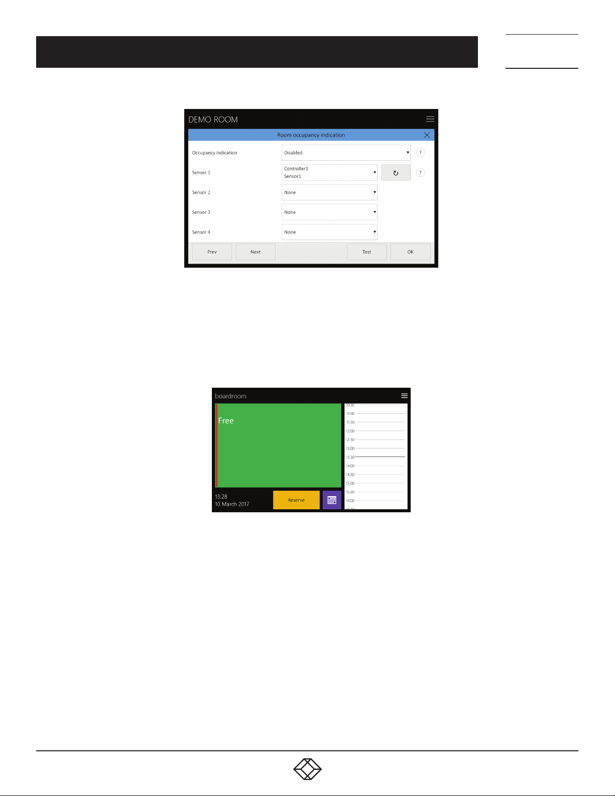
On the page “Room occupancy indication,“ you can set up the joining of room occupancy sensors and enable the displaying of
information from these sensors on the panels. Sensor data can also be used to automatically confirm meetings. Room occupancy
sensors have to be joined to the controller of the control system and the ReservationSystemOccupancySensorIntegration applet
has to be running in the controller program. Through this applet, the IN-SESSION Room Scheduler reservation system panels
communicate with the controllers of the IN-SESSION control system, transferring data from room occupancy sensors. For more
information on using the ReservationSystemOccupancySensorIntegration applet and joining the room occupancy sensors, see the
Help section of the integrated development environment IN-SESSION Visual Composer.
18
1. 87 7. 8 7 7. 2 26 9 BLACK BOX .COM
Page 19
NEED HELP?
LEAV E TH E TEC H TO US
LIVE 24/7
CHAPTER 3: ROOM SCHEDULER PANELS CONFIGURATION
FIGURE 3-18. ROOM OCCUPANCY INDICATION SCREEN
First of all, specify in the “Occupancy indication“ item how you wish room occupancy to be displayed on the panel. The setup of the
way of displaying information on room occupancy is shared by the whole control suite. The following options are available:
“Red and green stripe“. In this case, presence of people in the room is indicated by a vertical red stripe in the left part of the screen.
Absence of people is indicated by a green stripe.
TECHNICAL
SUPPORT
1. 8 7 7. 8 7 7. 2 2 6 9
FIGURE 3-19. RED AND GREEN STRIPE SCREEN SETUP
1. 87 7. 8 7 7. 2 26 9 BLACK BOX .COM
19
Page 20
NEED HELP?
LEAV E TH E TEC H TO US
LIVE 24/7
CHAPTER 3: ROOM SCHEDULER PANELS CONFIGURATION
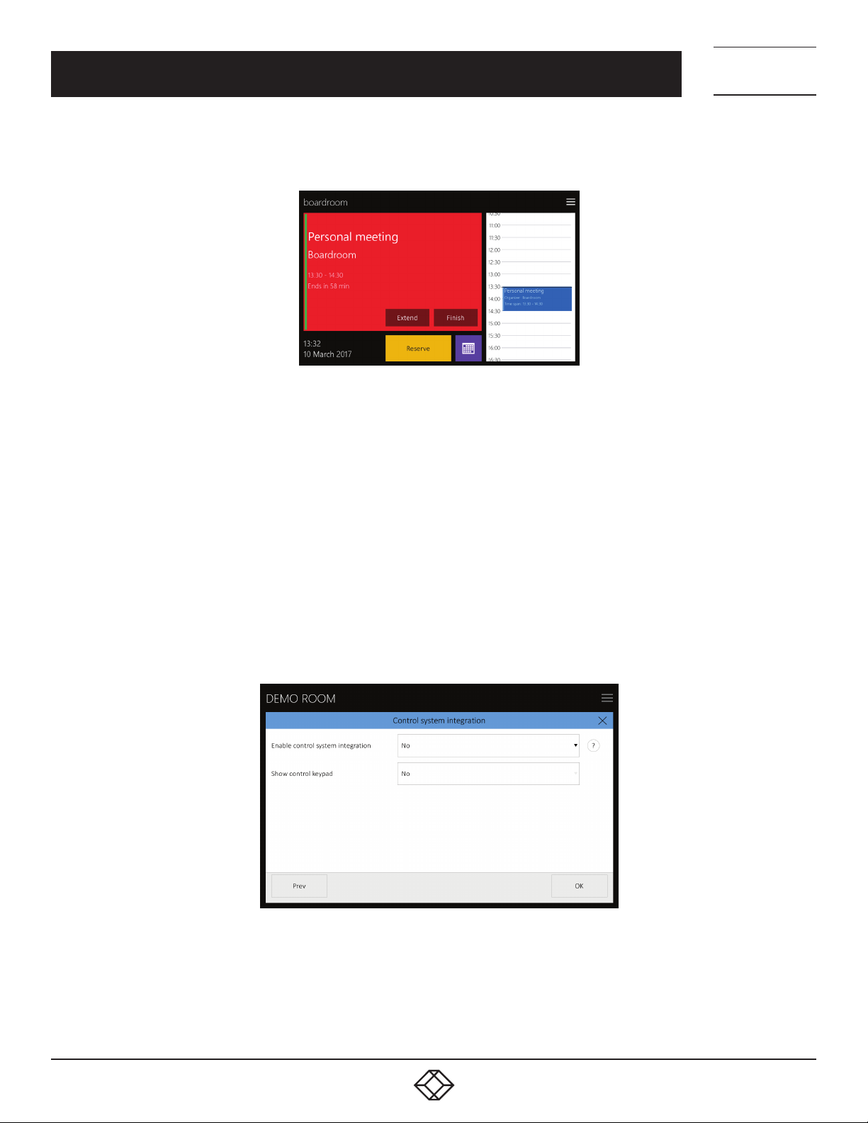
“Orange area”. If a meeting has been planned according to the calendar but nobody is in the room, the color of the main screen will
change from red to orange.
FIGURE 3-20. ORANGE ARE A SCREEN SETUP
In the fields Sensor 1—Sensor 4, you can specify which occupancy sensors are used in a given room. There can be up to four
sensors in one room from which occupancy information will be taken. In setting the sensors, the local network must involve
aconnected controller of the IN-SESSION control system with the ReservationSystemOccupancySensorIntegration applet. After
pressing the button for sensor identification (“Π”), the panel will search for available sensors in the network and show them in
adrop-down listbox. Sensors are identified by the magic name of the controller and the name of the sensor. If there are no sensors
in certain rooms, select “None” in the fields Sensor 1—Sensor 4. By pressing the “Test” button, you can test communication with the
controller to which sensors are attached.
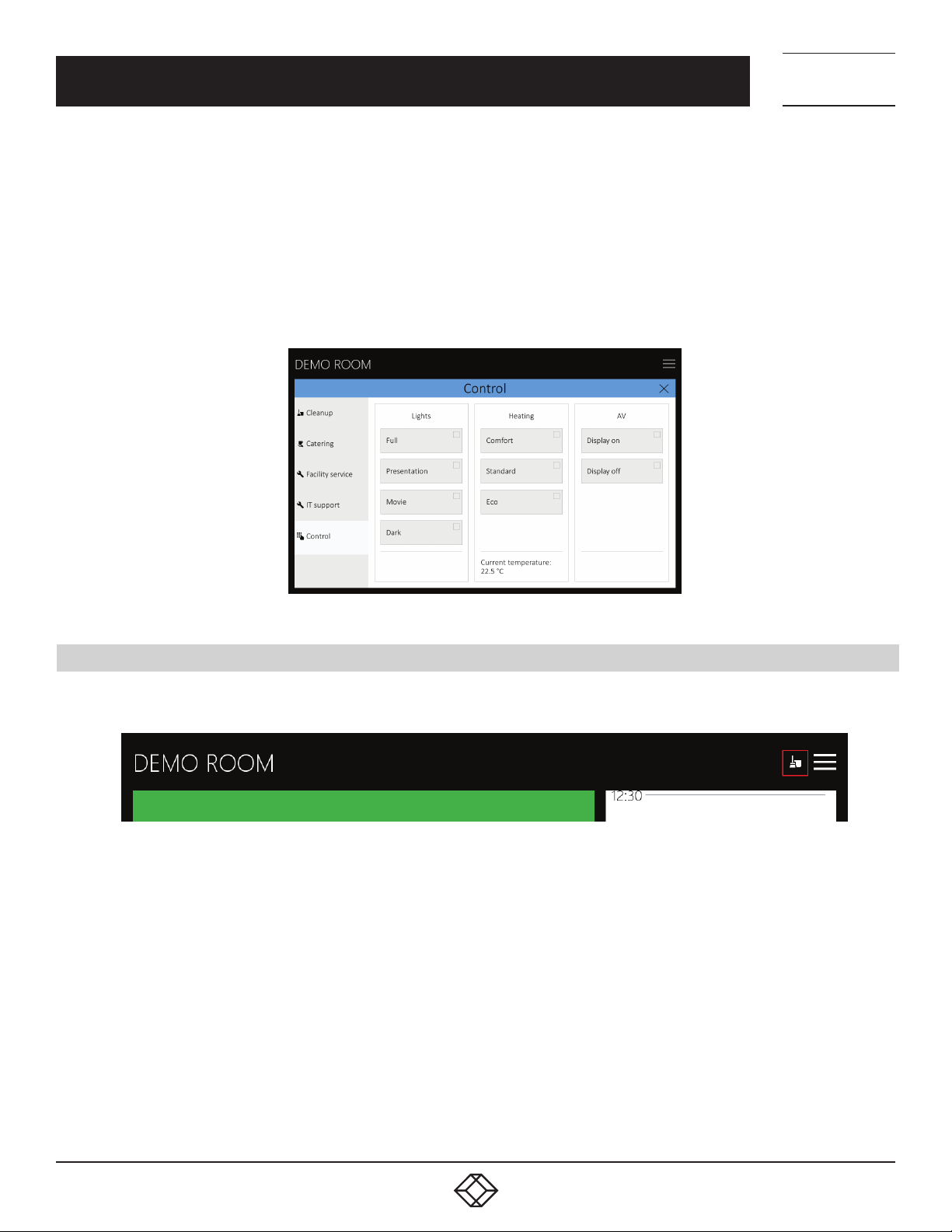
By pressing “Next,“ you can proceed to the “Control system integration“ page. Here you can set in which way the IN-SESSION
reservation system panel will communicate with the IN-SESSION control system. For the reservation system panel to communicate
with the control system, the ReservationSystemControlIntegration applet has to be running within the program of the controller or
the control system touchpanel. Through this applet, the IN-SESSION reservation system panels communicate with the IN-SESSION
control system units. For more information on using the ReservationSystemControlIntegration applet, see the Help section of the
IN-SESSION Visual Composer integrated development environment.
TECHNICAL
SUPPORT
1. 8 7 7. 8 7 7. 2 2 6 9
20
FIGURE 3-21. CONTROL ROOM INTEGRATION SCREEN
1. 87 7. 8 7 7. 2 26 9 BLACK BOX .COM
Page 21
NEED HELP?
LEAV E TH E TEC H TO US
LIVE 24/7
CHAPTER 3: ROOM SCHEDULER PANELS CONFIGURATION
In the item “Enable control system integration,“ you can enable communication of the reservation system panel with the INSESSION control system. This makes it possible for reservation system panels to transfer information on room occupancy and
currently running meetings to the control system.
In the item “Show control keypad,“ you can enable the displaying of the control keyboard on the reservation system panel. The user
can then activate the keypad by pressing the options button in the upper right corner of the screen and then selecting “Control.“
By pressing the “OK” button, you can now end the panel configuration and save the settings.
The look of the keypad can be set up in the control system program and in the properties of the
ReservationSystemControlIntegration applet. The following picture shows an example of a control keypad.
TECHNICAL
SUPPORT
1. 8 7 7. 8 7 7. 2 2 6 9
FIGURE 3-22. CONTROL PANEL KEYPAD EXAMPLE
3.6 USING THE ROOM SUPPORT SERVICES
If a service available for a given room is active, an options button will appear in the upper right corner of the panel.
FIGURE 3-23. OPTIONS BUTTON
When you press this button, a page with additional functions of the reservation system will be shown. On the left, you can select the
page with the required type of service:
“Cleanup“.
“Catering“.
Request for the first service department—displays the name of the first service department that you have entered the item
“Displayed name”, e.g. “Facility service.”
Request for the second service department—displays the name of the second service department that you have entered the item
“Displayed name”, e.g. “IT support.”
1. 87 7. 8 7 7. 2 26 9 BLACK BOX .COM
21
Page 22
NEED HELP?
LEAV E TH E TEC H TO US
LIVE 24/7
CHAPTER 3: ROOM SCHEDULER PANELS CONFIGURATION
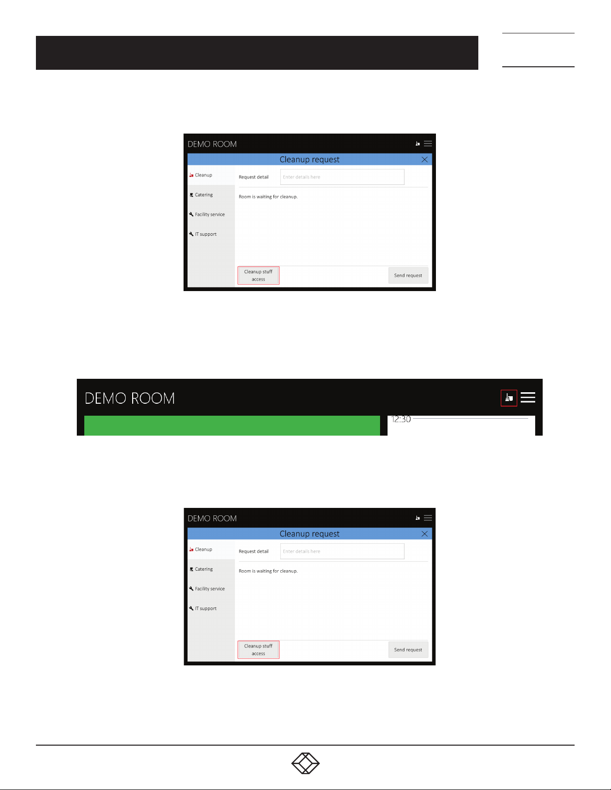
On the “Cleanup“ page, you can send a cleanup request by pressing “Send request.“ In the field “Request detail,“ you can enter any
details concerning the requested cleanup.
FIGURE 3-24. CLEANUP REQUEST SCREEN
TECHNICAL
SUPPORT
1. 8 7 7. 8 7 7. 2 2 6 9
After the email is sent, an icon appears in the upper right corner indicating that the room is waiting for cleanup.
FIGURE 3-25. ROOM AWAITING CLEANUP ICON
After the room has been cleaned up, the cleanup staff has to press the “Cleanup staff access“ button.
22
FIGURE 3-26. CLEANUP STAFF ACCESS BUTTON
1. 87 7. 8 7 7. 2 26 9 BLACK BOX .COM
Page 23
NEED HELP?
LEAV E TH E TEC H TO US
LIVE 24/7
CHAPTER 3: ROOM SCHEDULER PANELS CONFIGURATION
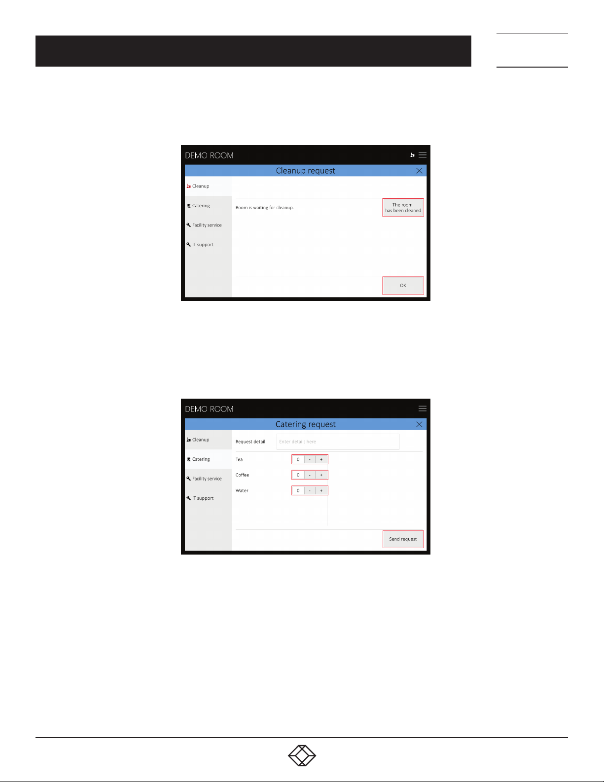
Now the cleanup staff is asked to enter PIN for cleanup. After doing so, they get to the page where they set the room as cleaned by
pressing “The room has been cleaned.“ This step deletes the icon indicating the room was waiting for cleanup. Leave the page by
pressing “OK“.
TECHNICAL
SUPPORT
1. 8 7 7. 8 7 7. 2 2 6 9
FIGURE 3-27. ROOM CLEANED SCREEN
On the “Catering“ page, you can create and send a catering request. By pressing “+“ and “- “ next to each item, you can specify the
amount of requested refreshments. After clicking on the field with the number of items, a numeric keypad will appear where you
can directly set the requested number of items. In the field “Request detail“ you can specify any details of your order. Send your
email by clicking on “Send request.“
FIGURE 3-28. CATERING REQUEST SCREEN
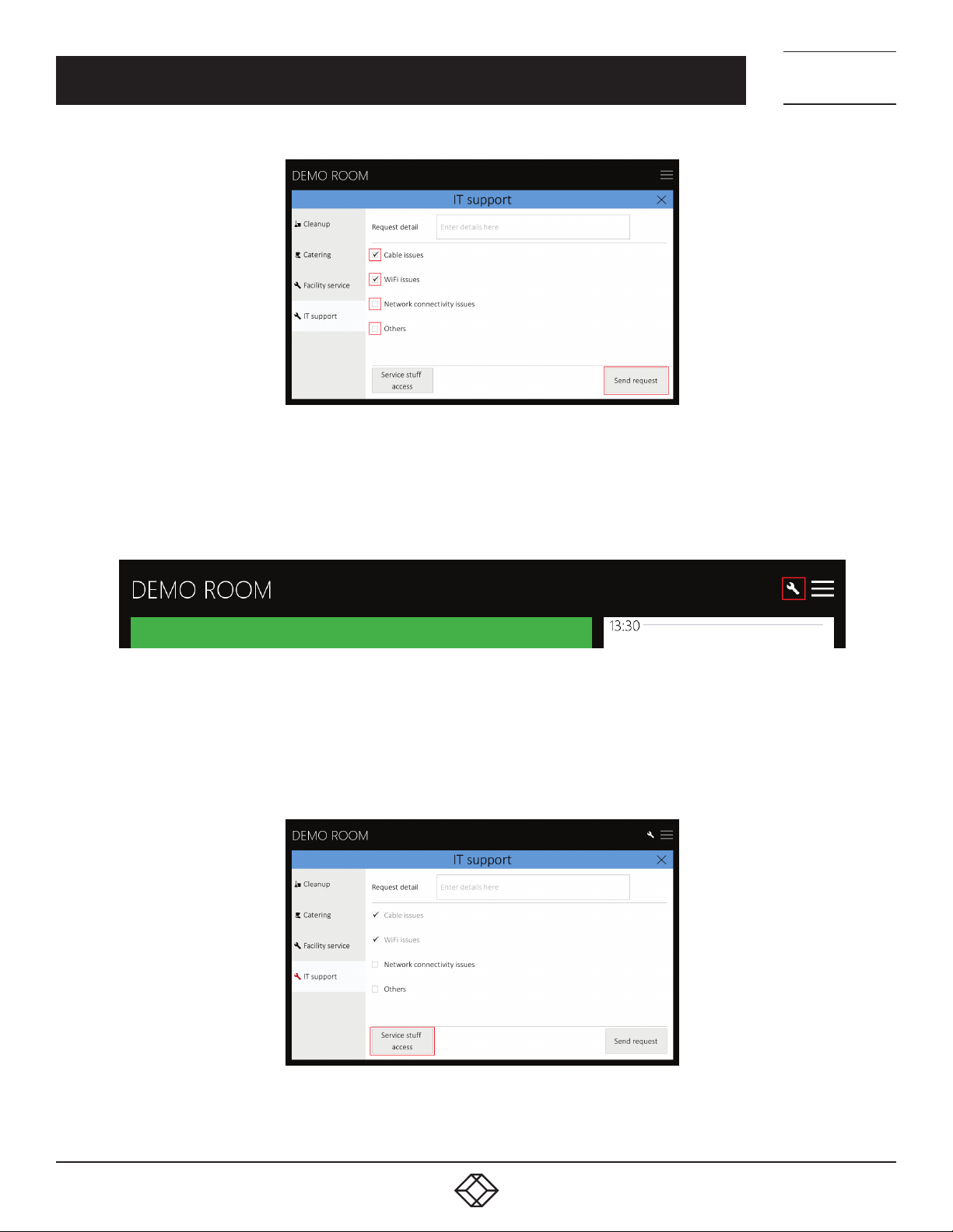
On the page for sending requests to technical support departments (in our example they are called “Facility service“ and “IT
support“), you can create a request addressed to the service department. Use checkboxes to indicate the problem/s that you wish
to report. In the “Request detail“ field, you can specify any details of your request. If you use the option “Others,” filling in the field
“Request details” is mandatory. Send your email by clicking on “Send request.“
1. 87 7. 8 7 7. 2 26 9 BLACK BOX .COM
23
Page 24
CHAPTER 3: ROOM SCHEDULER PANELS CONFIGURATION
FIGURE 3-29. IT SUPPORT SCREEN
After the email is sent, an icon indicating that the room is waiting for repair will appear in the upper right corner.
NEED HELP?
LEAV E TH E TEC H TO US
LIVE 24/7
TECHNICAL
SUPPORT
1. 8 7 7. 8 7 7. 2 2 6 9
FIGURE 3-30. ROOM WAITING FOR REPAIR ICON
After the service department solves the reported problem/s, technical support staff have to press the “Service staff access”
button.
FIGURE 3-31. SERVICE STAFF ACCESS BUT TON
24
1. 87 7. 8 7 7. 2 26 9 BLACK BOX .COM
Page 25
NEED HELP?
LEAV E TH E TEC H TO US
LIVE 24/7
CHAPTER 3: ROOM SCHEDULER PANELS CONFIGURATION
TECHNICAL
SUPPORT
1. 8 7 7. 8 7 7. 2 2 6 9
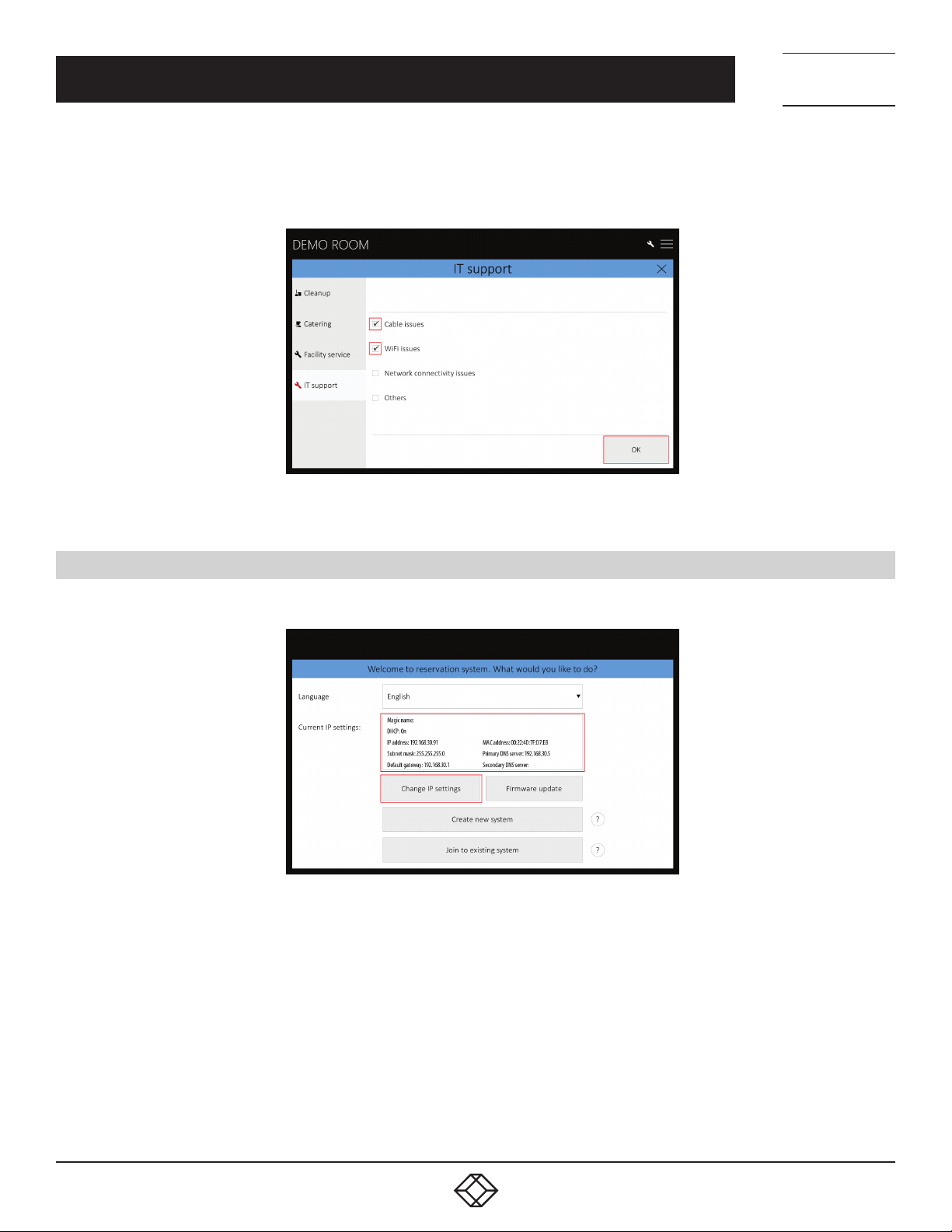
Now the service staff is asked to enter the PIN for service access. After doing so, they get to a page where checkmarks of repaired
items can be removed. As soon as all reported problems are solved (i.e. no checkbox is active), the icon indicating the room was
waiting for repair disappears. Leave the page by pressing “OK.”
FIGURE 3-32. IT SUPPORT COMPLETED SCREEN
3.7 IP SETTINGS
If you need to change the IP address settings, tap the “Change IP settings” on the opening setup screen.
FIGURE 3-33. OPENING SETUP SCREEN
1. 87 7. 8 7 7. 2 26 9 BLACK BOX .COM
25
Page 26
CHAPTER 3: ROOM SCHEDULER PANELS CONFIGURATION
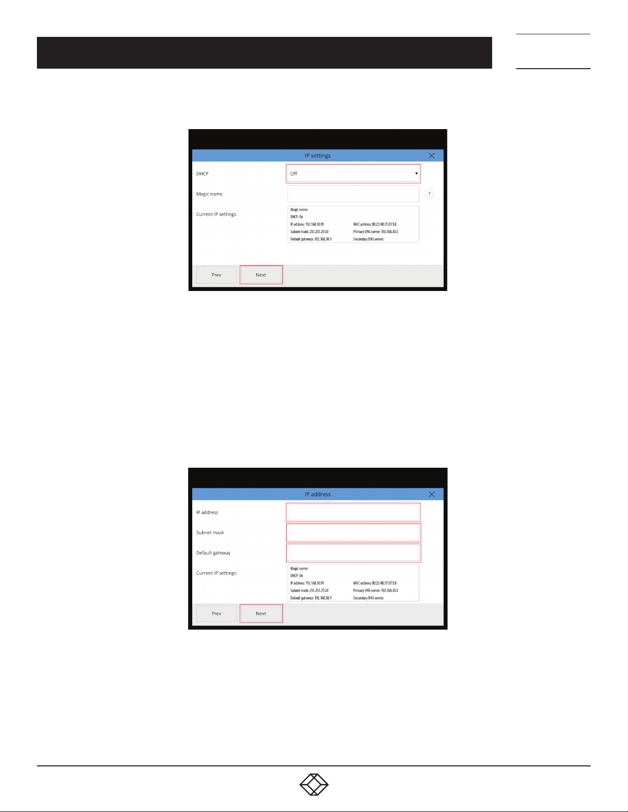
Turn off DHCP (dynamical distribution of IP addresses) on the following screen.
FIGURE 3-34. TURN OFF DHCP SCREEN
NEED HELP?
LEAV E TH E TEC H TO US
LIVE 24/7
TECHNICAL
SUPPORT
1. 8 7 7. 8 7 7. 2 2 6 9
“Magic name” is a unique name of a unit used in communication between reservation suite units. It is factory-set and there is
usually no need to change it. If you, however, need to change it, you must ensure the new name is unique in the specific local
network.
The current setting is displayed in the “Current IP settings” field. If you make any changes in the settings, save them by restarting
the panel so that the changes appear in this field.
For changes in the settings, tap “Next.”
On the next screen enter the IP address, Subnet mask and Default gateway of your network. Continue by tapping “Next.”
FIGURE 3-35. ENTER IP ADDRESS, SUBNET MASK, AND DEFAULT GATEWAY SCREEN
NOTE: In case you have switched on DHCP, you can set an alternate IP address in the identically named page. This page will be
displayed instead of the page “IP address“ if DHCP is On. This alternate IP address will be used in case of DHCP server failure.
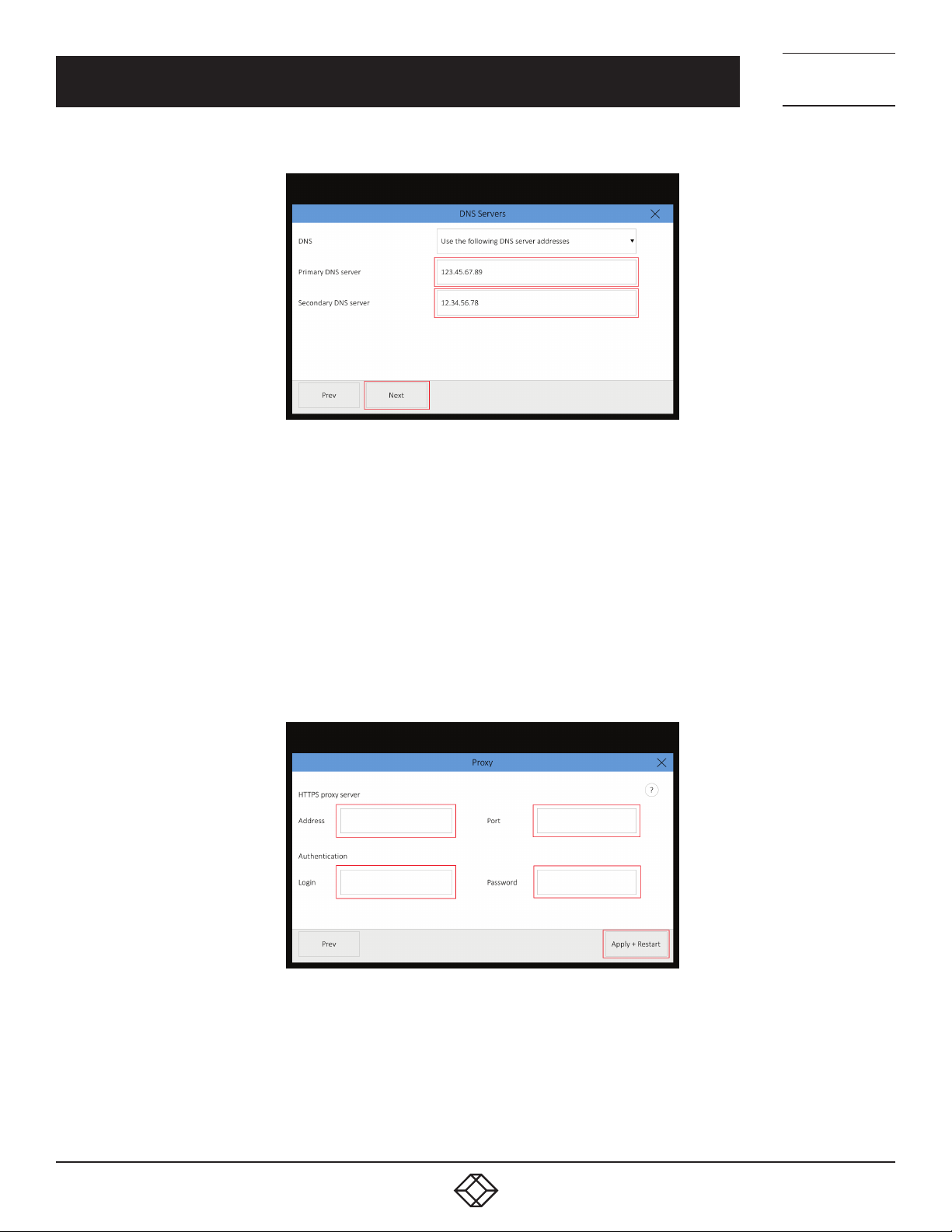
On the next screen, enter the IP addresses of primary and secondary DNS servers. Continue by tapping “Next.”
26
1. 87 7. 8 7 7. 2 26 9 BLACK BOX .COM
Page 27
CHAPTER 3: ROOM SCHEDULER PANELS CONFIGURATION
FIGURE 3-36. ENTER IP FOR PRIMARY AND SECONDARY DNS SERVERS
NEED HELP?
LEAV E TH E TEC H TO US
LIVE 24/7
TECHNICAL
SUPPORT
1. 8 7 7. 8 7 7. 2 2 6 9
NOTE: In case you need the IP address to be assigned by DHCP but the addresses of DNS servers to be set manually, proceed as
follows. On “IP settings” screen set DHCP to “On,” and then on the “DNS servers” screen, change “Obtain DNS server automatically”
to “Use the following DNS server address.”
If DHCP is turned off, the only available option is “Use the following DNS server address,” so the DNS servers’ addresses need to be
entered manually.
On the last screen, you can set up a proxy server if the proxy server is mandatory to access HTTPS servers on your network. Enter
the Address and Port of the proxy server. If the proxy server requires authentication, enter the credentials for the proxy server in the
“Login” and “Password.” Finish the settings by tapping “Apply + Restart.” The panel will now restart and the new IP settings will be
used.
FIGURE 3-37. PROXY SERVER SCREEN
If your LAN is secured using 802.1X, you can configure this protocol with Admin Web. See Section 4.5, IP Settings Using Admin
Web for instructions.
1. 87 7. 8 7 7. 2 26 9 BLACK BOX .COM
27
Page 28
CHAPTER 3: ROOM SCHEDULER PANELS CONFIGURATION
3.8 FIRMWARE UPDATE
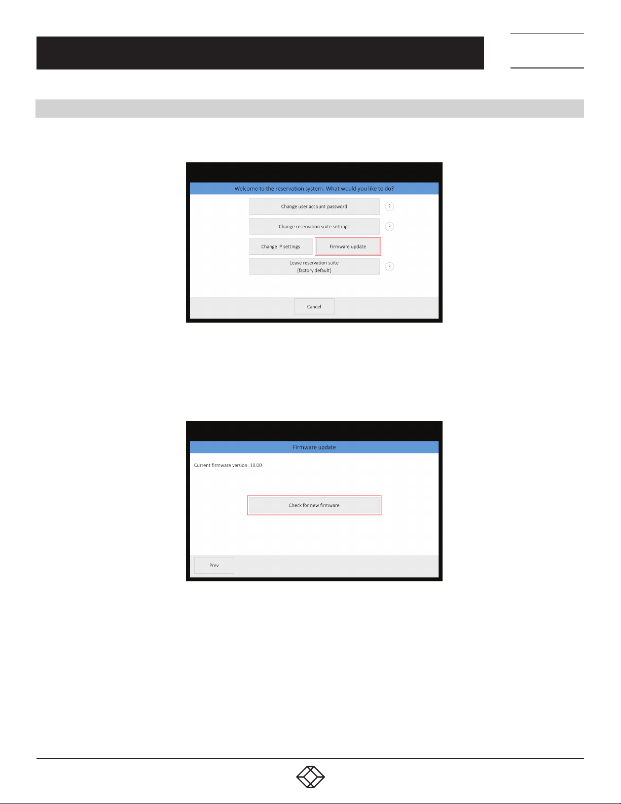
To check if newer firmware is available, tap the “Firmware update” button on the initial setup screen.
NEED HELP?
LEAV E TH E TEC H TO US
LIVE 24/7
TECHNICAL
SUPPORT
1. 8 7 7. 8 7 7. 2 2 6 9
FIGURE 3-38. FIRMWARE UPDATE BUTTON
The next screen shows current firmware. To check if newer firmware is available, contact Black Box Technical Support
at 877-877-2269 or [email protected]
FIGURE 3-39. CURRENT FIRMWARE
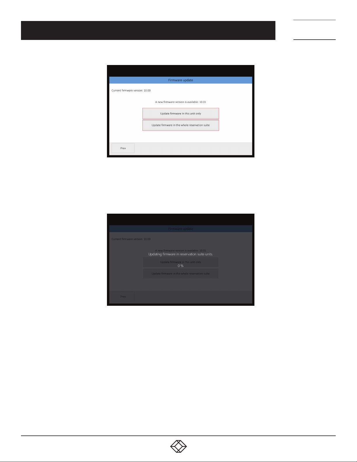
If newer firmware is available, you will see the following screen. Here you can choose whether you want to update the firmware in
this unit only or if you want to update the entire reservation suite by tapping the appropriate button
28
1. 87 7. 8 7 7. 2 26 9 BLACK BOX .COM
Page 29
CHAPTER 3: ROOM SCHEDULER PANELS CONFIGURATION
FIGURE 3-40. NEW FIRMWARE AVAILABLE SCREEN
NEED HELP?
LEAV E TH E TEC H TO US
LIVE 24/7
TECHNICAL
SUPPORT
1. 8 7 7. 8 7 7. 2 2 6 9
Firmware update takes approximately 1 minute and then the unit is restarted. Do not shut down or disconnect the power (LAN)
during the update, as this might damage the unit.
FIGURE 3-41. UPDATING FIRMWARE SCREEN
1. 87 7. 8 7 7. 2 26 9 BLACK BOX .COM
29
Page 30
NEED HELP?
LEAV E TH E TEC H TO US
LIVE 24/7
CHAPTER 4: CONFIGURATION THROUGH ADMIN WEB
Some settings of IN-SESSION Room Scheduler panels can be accessed through the Admin Web pages. The following possibilities
are offered:
Inserting a company logo
Firmware upgrade
Uploading G Suite certificate. This is described in the document IN-SESSION - Setup Guide - G Suite. If you use Microsoft Office 365
or Microsoft Exchange Server, this option is not relevant.
IP settings
Date and time settings
The Admin Web pages are available in the English language only.
4.1 ACCESSING ADMIN WEB
To access the Admin Web of IN-SESSION Room Scheduler panels, you need a computer with an internet browser. The computer
must be connected to the same LAN network as the IN-SESSION Room Scheduler panels. The Admin Web pages can be opened in
one of the following ways:
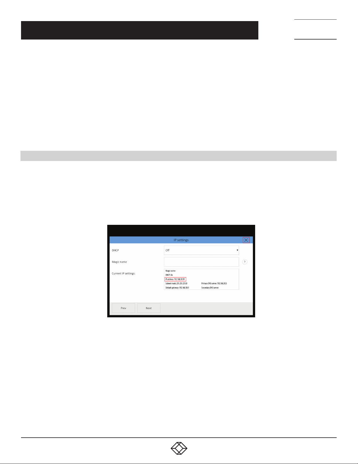
Option 1: Run the Internet browser on your PC and type in the IN-SESSION Room Scheduler panel IP address. To find out this
address, enter the setup screen of the IN-SESSION Room Scheduler panel (see Section 3.3, Detailed Panel Settings) and press the
Change IP settings button. On the following screen, you will see the current IP address. You can close the setup screen on the panel
without making any changes by tapping the cross in the corner.
TECHNICAL
SUPPORT
1. 8 7 7. 8 7 7. 2 2 6 9
30
FIGURE 4-1. OPTION 1
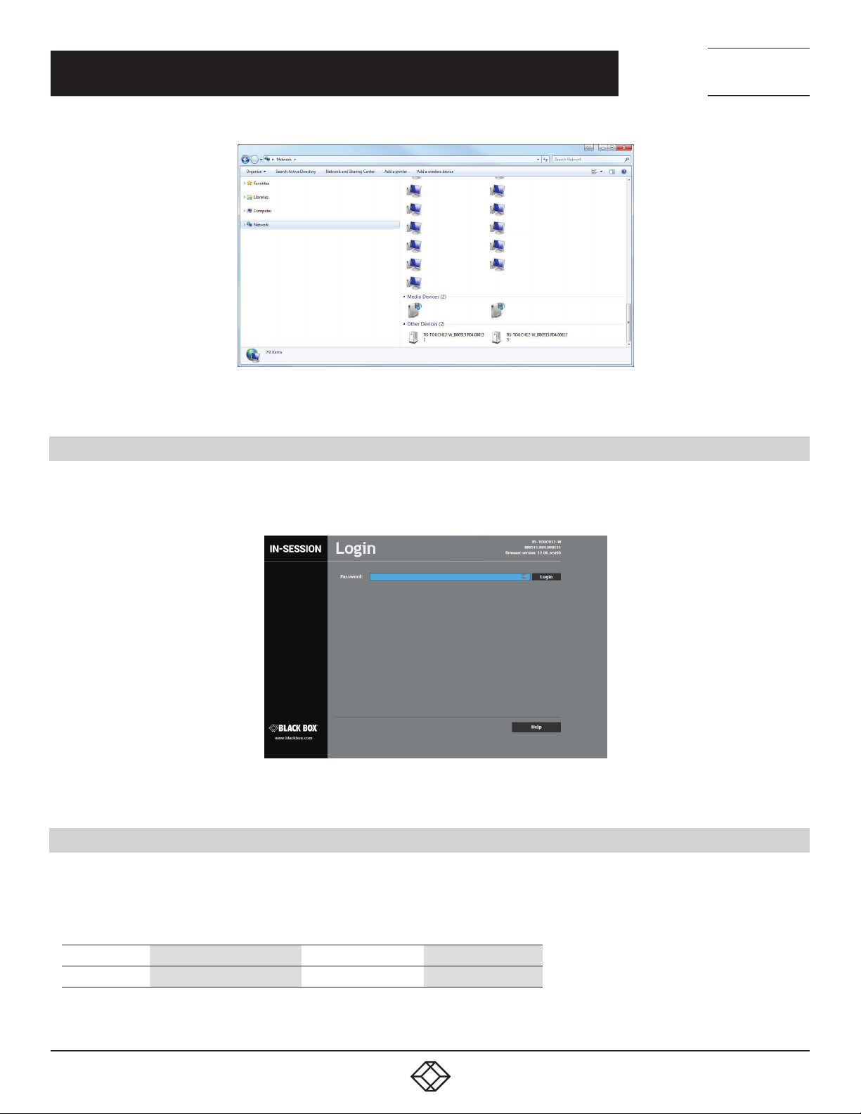
Option 2: Run File Explorer on your computer and select “Network” in the left part of the screen. On the right, you will see a list of
devices found in your network. The panels of the IN-SESSION systems can be found in the section “Other devices.” If you doubleclick the desired IN-SESSION Room Scheduler panel, the internet browser will start running, the panel IP address will be entered
automatically and the Admin Web of the given panel will open in the browser. To enable your computer to find the IN-SESSION
Room Scheduler panels, network identification has to be switched on your computer. In Windows 10, this can be done in the
following manner: Start / Settings / Network & Internet. Then select Wi-Fi (if your computer has a wireless connection to the
network) or Ethernet (if your computer is connected through a cable) in the left half of the screen. If you are connected by cable,
click on your network connection in the right part. If you are using Wi-Fi, click on the item “Advanced options“ below the list of
available Wi-Fi networks. Then set the item “Make this PC discoverable“ to “On.“
1. 87 7. 8 7 7. 2 26 9 BLACK BOX .COM
Page 31
CHAPTER 4: CONFIGURATION THROUGH ADMIN WEB
FIGURE 4-2. OPTION 2
NEED HELP?
LEAV E TH E TEC H TO US
LIVE 24/7
TECHNICAL
SUPPORT
1. 8 7 7. 8 7 7. 2 2 6 9
4.2 LOGIN
You have to log in first to operate your IN-SESSION Room Scheduler panel via these Admin Web pages. Enter your reservation suite
password into the “Password” box and click the “Login” button. Remember that the password is case sensitive. After entering the
password, you find yourself in the setup pages of Admin Web.
FIGURE 4-3. LOGIN SCREEN
4.3 INSERTING THE COMPANY LOGO
IN-SESSION Room Scheduler panels enable the user to insert a company logo in the upper right corner of the screen. The logo is
inserted in the PNG (Portable Network Graphics) format. The design supports the transparency feature (alpha channel). Use the
following sizes for the logo:
TYPE RECOMMENDED HEIGHT MAXIMUM HEIGHT MAXIMUM WIDTH
Your logo 60 pixels 100 pixels 500 pixels
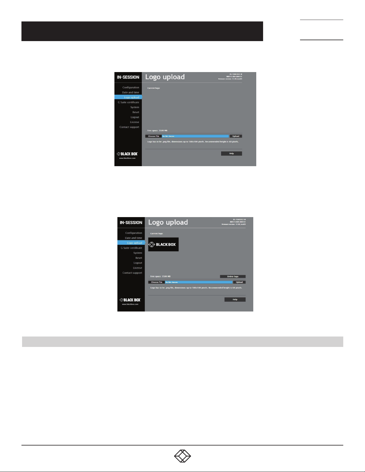
In the left column in the browser, select “Logo upload” and then click on “Choose file.” The standard dialogue window for the
opening of files will come up. In your computer, select a PNG file with the logo. When done, click the “Upload” button.
1. 87 7. 8 7 7. 2 26 9 BLACK BOX .COM
31
Page 32
CHAPTER 4: CONFIGURATION THROUGH ADMIN WEB
FIGURE 4-4. LOGO UPLOAD SCREEN
NEED HELP?
LEAV E TH E TEC H TO US
LIVE 24/7
TECHNICAL
SUPPORT
1. 8 7 7. 8 7 7. 2 2 6 9
After the logo is uploaded, the following screen is shown. Here you can check the logo—at this moment it is shown both on the
website and on the display. If you want to delete the logo, click “Delete logo.” If you want to change the logo, upload the new logo as
described on the previous page.
FIGURE 4-5. CHECK LOGO SCREEN
4.4 FIRMWARE UPDATE
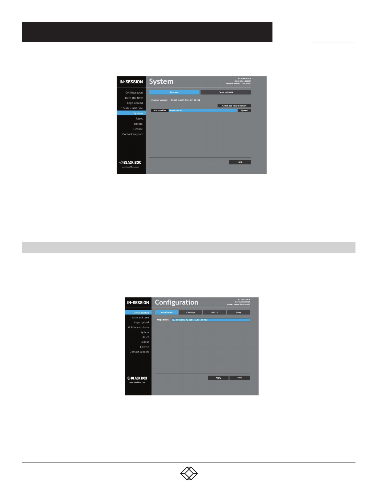
To upload more recent firmware to the IN-SESSION Room Scheduler panel, select the item “System” in the left column and then
click on “Firmware” in the upper part of the screen. If your network is connected to the internet, you can check the availability of
newer firmware on my.cuesystem.com server WHERE??? by clicking the button “Check for new firmware”. The IN-SESSION panel
verifies whether newer firmware is available on the Black Box website. If there is, it gets downloaded. Or, if you have the file with
newer firmware (*.cvcf), click on “Choose file”, select the file with firmware in your computer and click “Upload”.
You can also download firmware files into your computer on the website http://www.blackbox.com. The downloaded firmware
file is the ZIP type and includes firmware for all IN-SESSION units. Unzip the file into a suitable directory in your computer. The
firmware files are in the CVCF format. Then press the button “Choose file”, select the file with firmware for your IN-SESSION unit
and press “Upload”. In selecting the right CVCF file, check the name and serial number of your unit in the upper right part of the
web page, e.g. IN-SESSION-7-B, CS0494.R03.000003. The firmware file has to correspond to the name and first two parts of the
serial number. For example, to upgrade to firmware version 10.00a select the file IN-SESSION-7-B_CS0494.R03_Firmware_10.00a.
cvcf for the above-mentioned unit.
32
1. 87 7. 8 7 7. 2 26 9 BLACK BOX .COM
Page 33
CHAPTER 4: CONFIGURATION THROUGH ADMIN WEB
FIGURE 4-6. CHOOSE FIRMWARE FILE SCREEN
NEED HELP?
LEAV E TH E TEC H TO US
LIVE 24/7
TECHNICAL
SUPPORT
1. 8 7 7. 8 7 7. 2 2 6 9
After the file with new firmware is uploaded into the panel, apply new firmware by clicking “Update.”
The firmware upgrade takes about one minute and then the panel restarts. Do not shut down or disconnect the power (LAN) during
the update, as this might damage the unit.
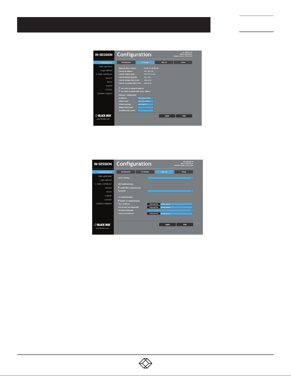
4.5 IP SETTINGS USING ADMIN WEB
You can also change the IP setting through Admin Web. In the left part, choose “Configuration.” If you select “Identification”
inthe upper left part, you can change the “Magic name” (see Section 3.7, IP settings). All changes made in Admin Web need to be
confirmed by clicking “Apply” before leaving the selected page, otherwise changes will not become effective.
FIGURE 4-7. IDENTIFICATION TAB
To change IP addresses, choose “IP settings” in the upper part of the screen. Here you can change the setting of IP addresses same
as in settings pages of the touch control of the IN-SESSION Room Scheduler panel (see the Section 3.7, IP settings). Be sure to click
the “Apply” button for any changes to become effective. Then confirm the change with “Yes” button. The panel will now restart and the
new IP settings will be used.
1. 87 7. 8 7 7. 2 26 9 BLACK BOX .COM
33
Page 34
NEED HELP?
LEAV E TH E TEC H TO US
LIVE 24/7
CHAPTER 4: CONFIGURATION THROUGH ADMIN WEB
FIGURE 4-8. IP SETTINGS TAB
If your LAN is secured using 802.1X, select the “802.1X” tab at the top. Supported authentication methods are MD5 and TLS.
TECHNICAL
SUPPORT
1. 8 7 7. 8 7 7. 2 2 6 9
FIGURE 4-9. 802.1X TAB
Type “Device identity” in the appropriate box.
If you are using MD5 authentication, check the appropriate checkbox and enter the password for MD5 authentication.
If you are using TLS authentication using a certificate, check the appropriate checkbox. Then tap the “Choose file” button next to
“User certificate,”,select the user certificate file and upload it. The following certificate types are supported: PKCS #12 and x509
(PEM, DER). You can also upload a private key file if the private key is not part of the user certificate. If the user certificate or private
key is encrypted, enter the password to decrypt it in the “Password (optional)” box.
In the CA certificate entry, upload the Radius server CA Certificate.
Click “Apply” to save the changes.
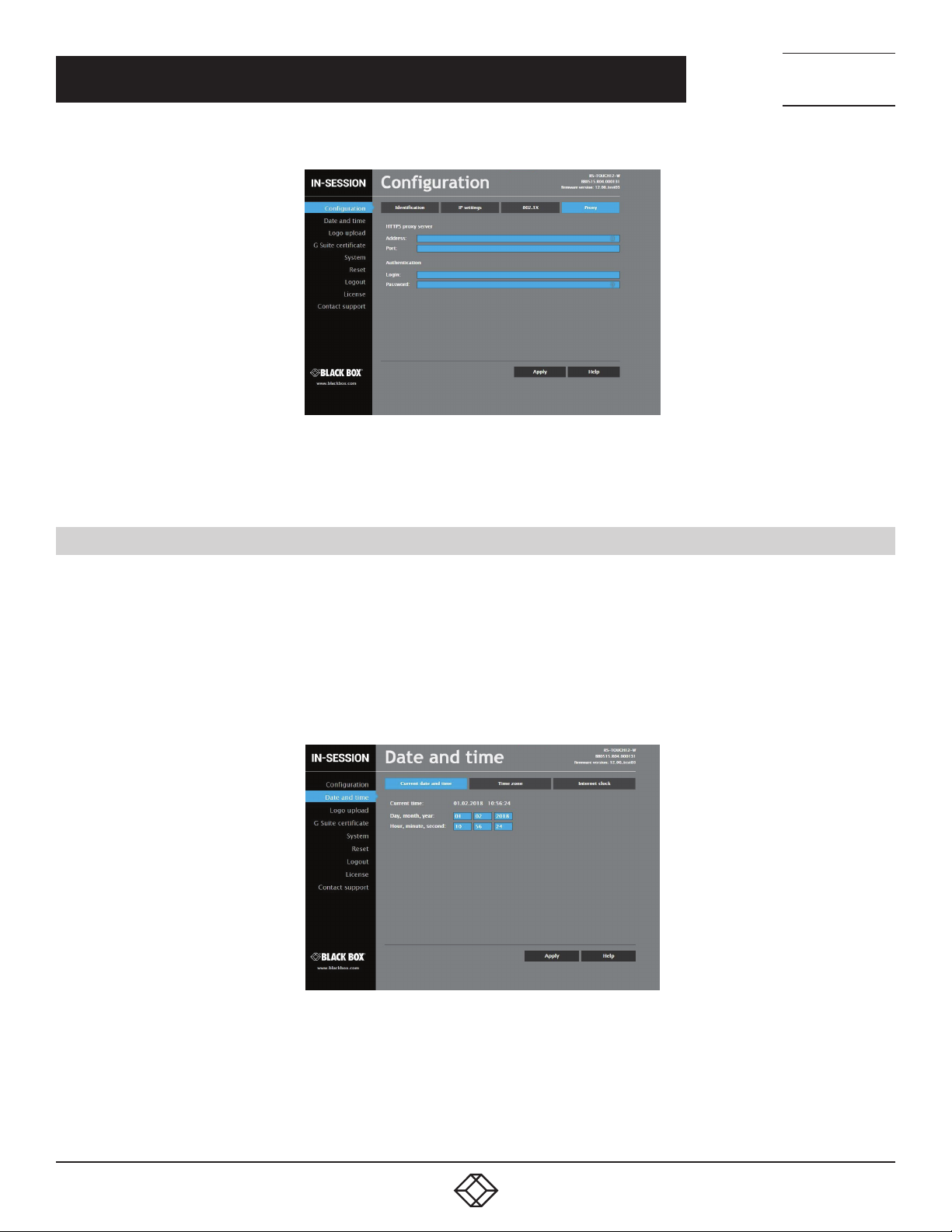
If the proxy server is mandatory to access HTTPS servers on your network, select the “Proxy” tab on the top. Enter Address and
Port of the proxy server. If the proxy server requires authentication, enter the credentials for the proxy server in the “Login” and
“Password.” Finish the settings by tapping “Apply + Restart.” The panel will now restart and the new IP settings will be used.
34
1. 87 7. 8 7 7. 2 26 9 BLACK BOX .COM
Page 35
NEED HELP?
LEAV E TH E TEC H TO US
LIVE 24/7
CHAPTER 4: CONFIGURATION THROUGH ADMIN WEB
TECHNICAL
SUPPORT
1. 8 7 7. 8 7 7. 2 2 6 9
FIGURE 4-10. PROXY TAB
Enter Address and Port of the proxy server. If the proxy server requires authentication, enter the credentials for the proxy server in
“Login” and “Password.” Click “Apply” to save the changes.
4.6 OTHER SETTINGS AVAILABLE IN ADMIN WEB
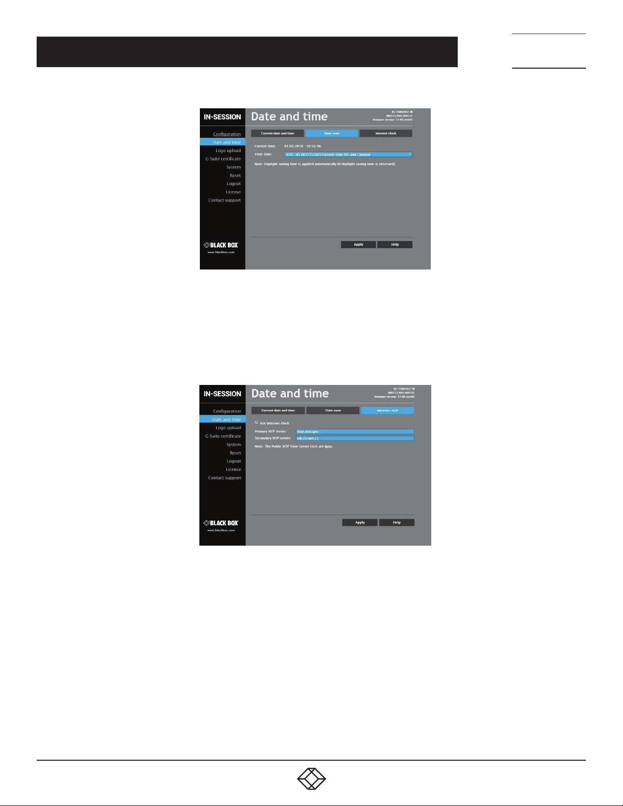
If you need to set the time of the panel, choose “Date and time” in the left half. To set the current time, click on “Current date and
time” in the upper part of the screen. The current date, time and time zone are shown on the “Current time” line. The applicable
boxes can be selected to enter changes to the:
date: day/month/year
time: hour/minute/second
Be sure to click the “Apply” button for any changes to become effective.
FIGURE 4-11. CURRENT DATE AND TIME SCREEN
To set the time zone, choose “Time zone” in the upper part of the screen. The current date, time and time zone are shown on the
“Current time” line. The Time zone box can be selected to enter changes to the time zone. Be sure to click the “Apply” button for any
changes to become effective.
1. 87 7. 8 7 7. 2 26 9 BLACK BOX .COM
35
Page 36
NEED HELP?
LEAV E TH E TEC H TO US
LIVE 24/7
CHAPTER 4: CONFIGURATION THROUGH ADMIN WEB
FIGURE 4-12. TIME ZONE TAB
If you want to change the setting of the servers of the internet time, choose “Internet clock.” This page is used for synchronization
of the IN-SESSION Room Scheduler panel’s date and time with the internet clock. Begin by selecting the check box for “Use
Internet clock.” Next, enter the IP addresses (or complete domain address names) of the primary and secondary NTP servers. Use
the Primary NTP server and Secondary NTP server boxes for this purpose. Be sure to click the “Apply” button for any changes to
become effective.
TECHNICAL
SUPPORT
1. 8 7 7. 8 7 7. 2 2 6 9
FIGURE 4-13. INTERNET CLOCK TAB
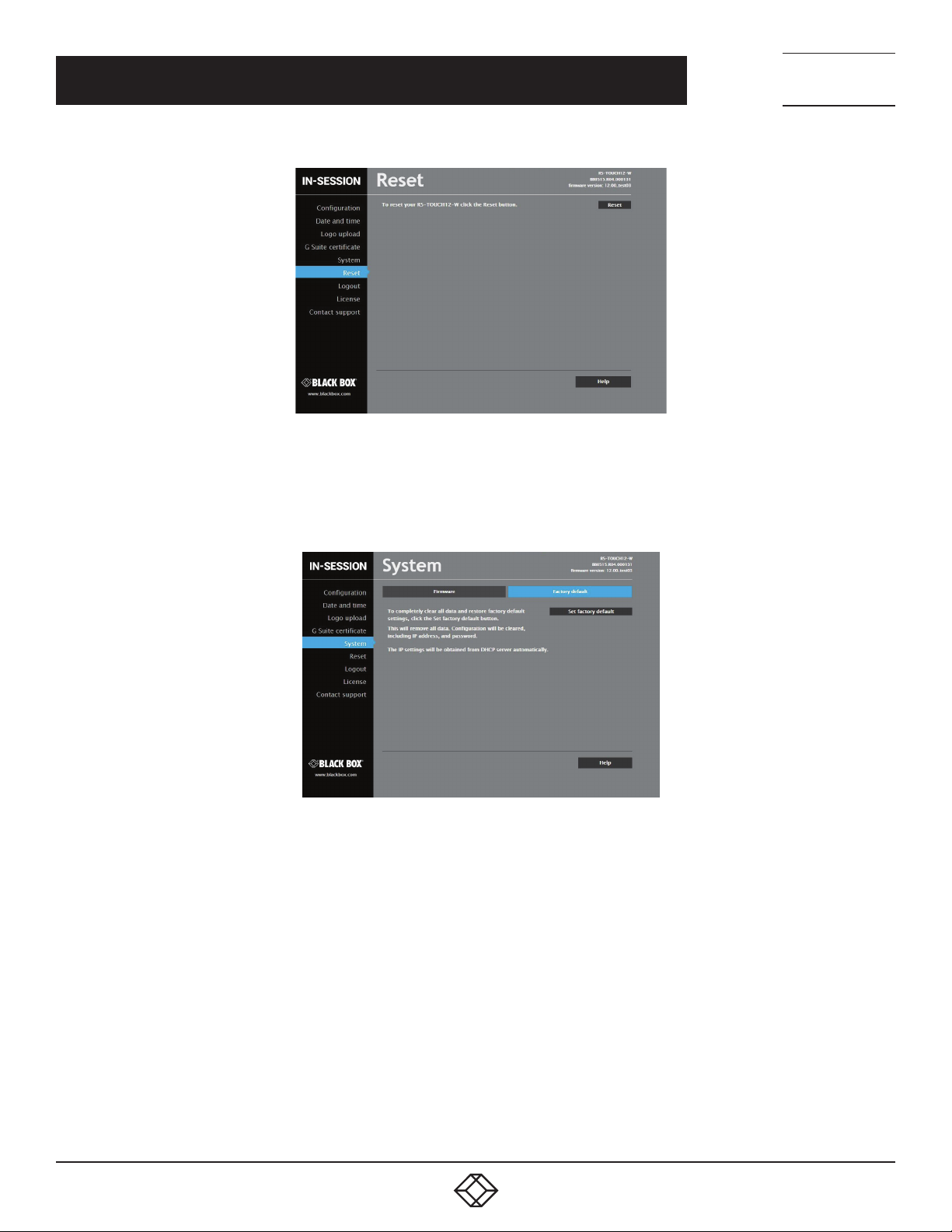
If you need to reset the panel, choose “Reset” in the left menu and then click “Reset” in the right part of the screen.
36
1. 87 7. 8 7 7. 2 26 9 BLACK BOX .COM
Page 37
NEED HELP?
LEAV E TH E TEC H TO US
LIVE 24/7
CHAPTER 4: CONFIGURATION THROUGH ADMIN WEB
FIGURE 4-14. RESET SCREEN
If you need to put the panel into the factory default mode, delete all user settings and leave the reservation suite, choose “System”
in the left menu, then “Factory default” in the upper part, and then click the button “Set factory default.” Confirm the deletion by the
“Yes” button or cancel it by the “Cancel” button.
TECHNICAL
SUPPORT
1. 8 7 7. 8 7 7. 2 2 6 9
FIGURE 4-15. SYSTEM SCREEN
If you choose “License” in the left menu, you will see a page describing the EULA software license.
1. 87 7. 8 7 7. 2 26 9 BLACK BOX .COM
37
Page 38

NEED HELP?
LEAV E TH E TEC H TO US
LIVE 24/7
CHAPTER 5: TECHNICAL SUPPORT
5.1 CONTACTING BLACK BOX
If you determine that your Room Scheduler is malfunctioning, do not attempt to alter or repair the unit. It contains no userserviceable parts. Contact Black Box Technical Support at 877-877-2269 or [email protected].
Before you do, make a record of the history of the problem. We will be able to provide more efficient and accurate assistance
if you have a complete description, including:
the nature and duration of the problem.
when the problem occurs.
the components involved in the problem.
any particular application that, when used, appears to create the problem or make it worse.
TECHNICAL
SUPPORT
1. 8 7 7. 8 7 7. 2 2 6 9
5.2 SHIPPING AND PACKAGING
If you need to transport or ship your Room Scheduler:
Package it carefully. We recommend that you use the original container.
If you are returning the unit, make sure you include everything you received with it. Before you ship for return or repair,
contact Black Box to get a Return Authorization (RA) number.
38
1. 87 7. 8 7 7. 2 26 9 BLACK BOX .COM
Page 39

NEED HELP?
LEAV E TH E TEC H TO US
LIVE 24/7
APPENDIX A: REGULATORY INFORMATION
A.1 FCC STATEMENT
This equipment has been found to comply with the limits for a Class A digital device, pursuant to Part 15 of the FCC Rules. These
limits are designed to provide reasonable protection against harmful interference when the equipment is operated in a commercial
environment. This equipment generates, uses, and can radiate radio frequency energy and, if not installed and used in accordance
with the instruction manual, may cause harmful interference to radio communications. Operation of this equipment in a residential
area is likely to cause harmful interference in which case the user will be required to correct the interference at his own expense.
Changes or modifications not expressly approved by the party responsible for compliance could void the user’s authority to
operate the equipment.
Shielded cables must be used with this equipment to maintain compliance with radio frequency energy emission regulations and
ensure a suitably high level of immunity to electromagnetic disturbances.
All power supplies are certified to the relevant major international safety standards.
TECHNICAL
SUPPORT
1. 8 7 7. 8 7 7. 2 2 6 9
1. 87 7. 8 7 7. 2 26 9 BLACK BOX .COM
39
Page 40

NEED HELP?
LEAV E TH E TEC H TO US
LIVE 24/7
APPENDIX A: REGULATORY INFORMATION
A.2 NOM STATEMENT
1. Todas las instrucciones de seguridad y operación deberán ser leídas antes de que el aparato eléctrico sea operado.
2. Las instrucciones de seguridad y operación deberán ser guardadas para referencia futura.
3. Todas las advertencias en el aparato eléctrico y en sus instrucciones de operación deben ser respetadas.
4. Todas las instrucciones de operación y uso deben ser seguidas.
5. El aparato eléctrico no deberá ser usado cerca del agua—por ejemplo, cerca de la tina de baño, lavabo, sótano mojado o cerca
de una alberca, etc.
6. El aparato eléctrico debe ser usado únicamente con carritos o pedestales que sean recomendados por el fabricante.
7. El aparato eléctrico debe ser montado a la pared o al techo sólo como sea recomendado por el fabricante.
8. Servicio—El usuario no debe intentar dar servicio al equipo eléctrico más allá a lo descrito en las instrucciones de operación.
Todo otro servicio deberá ser referido a personal de servicio calificado.
9. El aparato eléctrico debe ser situado de tal manera que su posición no interfiera su uso. La colocación del aparato eléctrico
sobre una cama, sofá, alfombra o superficie similar puede bloquea la ventilación, no se debe colocar en libreros o gabinetes que
impidan el flujo de aire por los orificios de ventilación.
10. El equipo eléctrico deber ser situado fuera del alcance de fuentes de calor como radiadores, registros de calor, estufas u otros
aparatos (incluyendo amplificadores) que producen calor.
11. El aparato eléctrico deberá ser connectado a una fuente de poder sólo del tipo descrito en el instructivo de operación, o como
se indique en el aparato.
12. Precaución debe ser tomada de tal manera que la tierra fisica y la polarización del equipo no sea eliminada.
13. Los cables de la fuente de poder deben ser guiados de tal manera que no sean pisados ni pellizcados por objetos colocados
sobre o contra ellos, poniendo particular atención a los contactos y receptáculos donde salen del aparato.
14. El equipo eléctrico debe ser limpiado únicamente de acuerdo a las recomendaciones del fabricante.
15. En caso de existir, una antena externa deberá ser localizada lejos de las lineas de energia.
16. El cable de corriente deberá ser desconectado del cuando el equipo no sea usado por un largo periodo de tiempo.
17. Cuidado debe ser tomado de tal manera que objectos liquidos no sean derramados sobre la cubierta u orificios de ventilación.
18. Servicio por personal calificado deberá ser provisto cuando:
A: El cable de poder o el contacto ha sido dañado; u
B: Objectos han caído o líquido ha sido derramado dentro del aparato;o
C: El aparato ha sido expuesto a la lluvia; o
D: El aparato parece no operar normalmente o muestra un cambio en su desempeño; o
E: El aparato ha sido tirado o su cubierta ha sido dañada.
TECHNICAL
SUPPORT
1. 8 7 7. 8 7 7. 2 2 6 9
40
1. 87 7. 8 7 7. 2 26 9 BLACK BOX .COM
Page 41
NEED HELP?
LEAV E TH E TEC H TO US
LIVE 24/7
APPENDIX B: DISCLAIMER/TRADEMARKS
TECHNICAL
SUPPORT
1. 8 7 7. 8 7 7. 2 2 6 9
B.1 DISCLAIMER
Black Box Corporation shall not be liable for damages of any kind, including, but not limited to, punitive, consequential or cost of cover
damages, resulting from any errors in the product information or specifications set forth in this document and Black Box Corporation
may revise this document at any time without notice.
B.2 TRADEMARKS USED IN THIS MANUAL
Black Box and the Black Box logo type and mark are registered trademarks of Black Box Corporation.
Any other trademarks mentioned in this manual are acknowledged to be the property of the trademark owners.
1. 87 7. 8 7 7. 2 26 9 BLACK BOX .COM
41
Page 42

NOTES
_________________________________________________________________________________________________
_
_________________________________________________________________________________________________
_
_________________________________________________________________________________________________
_
_
_________________________________________________________________________________________________
NEED HELP?
LEAV E TH E TEC H TO US
LIVE 24/7
TECHNICAL
SUPPORT
1. 8 7 7. 8 7 7. 2 2 6 9
_________________________________________________________________________________________________
_
_________________________________________________________________________________________________
_\
_________________________________________________________________________________________________
_
_________________________________________________________________________________________________
_
_________________________________________________________________________________________________
_
_________________________________________________________________________________________________
_
42
_________________________________________________________________________________________________
_________________________________________________________________________________________________
__
________________________________________________________________________________________________
1. 87 7. 8 7 7. 2 26 9 BLACK BOX .COM
Page 43

NOTES
________________________________________________________________________________________________
__
________________________________________________________________________________________________
__
________________________________________________________________________________________________
__
_
________________________________________________________________________________________________
_
NEED HELP?
LEAV E TH E TEC H TO US
LIVE 24/7
TECHNICAL
SUPPORT
1. 8 7 7. 8 7 7. 2 2 6 9
________________________________________________________________________________________________
__
________________________________________________________________________________________________
_ _\
________________________________________________________________________________________________
__
________________________________________________________________________________________________
__
________________________________________________________________________________________________
__
________________________________________________________________________________________________
__
________________________________________________________________________________________________
_
________________________________________________________________________________________________
___
________________________________________________________________________________________________
1. 87 7. 8 7 7. 2 26 9 BLACK BOX .COM
43
Page 44

NEED HELP?
LEAVE THE TECH TO US
LIVE 24/7
TECHNICAL
SUPPORT
1.8 7 7. 8 7 7. 2 2 69
© COPYRIGHT 2018 BLACK BOX CORPORATION. ALL RIGHTS RESERVED.
 Loading...