

Page 1
USER MANUAL
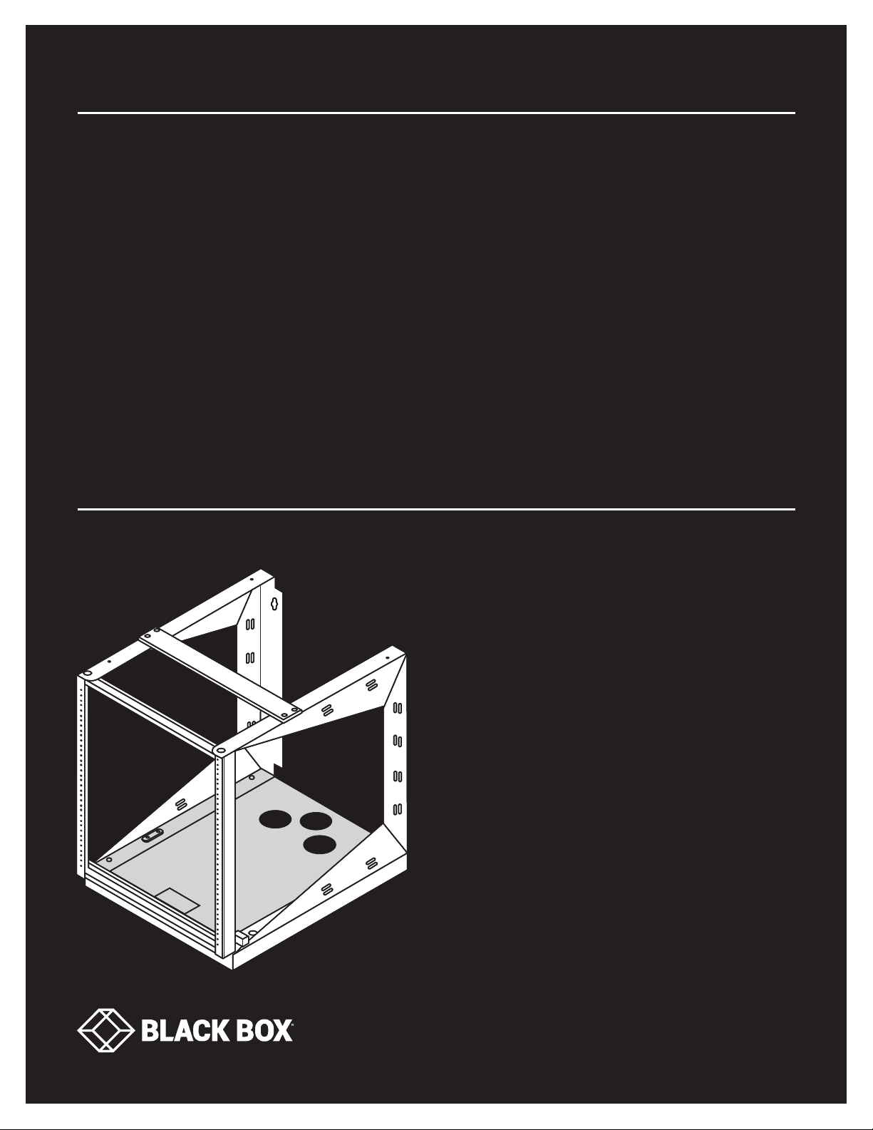
RM050A-R3, RM051A-R3
ULTR A
WALLMOUNT
RACKS
24/7 TECHNICAL SUPPORT AT 1.877.877.2269 OR VISIT BLACKBOX.COM
Page 2
NEED HELP?
LEAV E TH E TEC H TO US
LIVE 24/7
TABLE OF CONTENTS
TECHNICAL
SUPPORT
1. 8 7 7. 8 7 7. 2 2 69
PREFACE ............................................................................................................................................................................................ 3
Safety Symbols Used in this Manual ............................................................................................................................................................ 3
Safety Considerations ....................................................................................................................................................................................3
1. SPECIFICATIONS ........................................................................................................................................................................... 4
1.1 Dimensions ...............................................................................................................................................................................................4
1.2 General Specifications .............................................................................................................................................................................4
1.3 RM050A-R3 Drawings .............................................................................................................................................................................. 5
1.4 RM051A-R3 Drawings .............................................................................................................................................................................. 8
2. OVERVIE W .................................................................................................................................................................................... 11
2.1 Introduction .............................................................................................................................................................................................11
2.2 Features .................................................................................................................................................................................................. 11
2.3 What’s Included ...................................................................................................................................................................................... 11
2.4 Service.....................................................................................................................................................................................................11
3. MOUNTING INSTRUCTIONS ...................................................................................................................................................... 12
3.1 Receiving, Unpacking and Removing the Ultra Wallmount Rack from the Carton ........................................................................... 12
3.2 Wood Studded Wall ................................................................................................................................................................................ 12
3.3 Masonry Wall Surface ............................................................................................................................................................................ 12
3.4 Loading Equipment ................................................................................................................................................................................13
3.5 Power .......................................................................................................................................................................................................13
3.6 Protective Grounding ............................................................................................................................................................................. 13
3.6.1 Connecting the Main Protective Grounding Stud to the Dedicated Branch Circuit Grounding Conductor ................................... 13
3.6.2 Connecting the Main Protective Grounding Stud to the Protective Bonding Conductors ................................................................ 13
APPENDIX: DISCLAIMER/TRADEMARKS ..................................................................................................................................... 12
A.1 Disclaimer ............................................................................................................................................................................................... 12
A.2 Trademarks Used in this Manual .......................................................................................................................................................... 12
2
1. 87 7. 8 7 7. 2 26 9 BLACK BOX .COM
Page 3
NEED HELP?
LEAV E TH E TEC H TO US
LIVE 24/7
PREFACE
This manual is provided to prevent service personnel from committing an act that results in the risk of fire, electric shock, or
injury to persons. Only trained service personnel should receive, unpack, and assemble the Ultra Wallmount Rack. In addition, only
trained service personnel should install equipment in the rack.
SAFETY SYMBOLS USED IN THIS MANUAL
This manual is provided to prevent service personnel from committing an act that results in the risk of fire, electric shock, or injury.
WARNING: Failure to follow directions in the warning could result in injury to persons or loss of life.
TECHNICAL
SUPPORT
1. 8 7 7. 8 7 7. 2 2 69
CAUTION: Failure to follow directions in the caution could result in damage to equipment or storage data.
SAFETY CONSIDERATIONS
WARNING: Improper handling and use of the Ultra Wallmount Rack could result in equipment damage, serious injury,
or possible death.
Only trained service personnel should be used to remove the rack from the carton. Also be sure you have a sufficient number
of service personnel. Do not attempt to move racks by yourself.
Only UL
Be sure to read and follow all individual manufacturer equipment manuals for safety and installation instructions.
Proper spacing is required when installing electrical equipment to avoid electrical shock.
Maintain minimum spacing between the accessories and components and the Ultra Wallmount Rack for safe operation
of the equipment when installed in accordance with the National Electric Code ANSI/NFPA 70-1999.
The ambient temperature operating range for the Ultra Wallmount Rack and accessories is +50 to +95° F (+10 to +35° C).
The non-operating temperature is -4 to +140° F (-20 to +60° C).
®
Listed ITE units should be installed in the Ultra Wallmount Rack.
1. 87 7. 8 7 7. 2 26 9 BLACK BOX .COM
3
Page 4
CHAPTER 1: SPECIFICATIONS
1.1 DIMENSIONS
Table 1-1 lists specifications for the rack shown in Figures 1-1 through 1-10.
TABLE 1-1. DIMENSIONS SPECIFICATIONS
PART NUMBER # OF RACK UNITS (RU) HEIGHT WIDTH DEPTH
RM050A-R3 11 23.57" (59.86 cm) 19.8" (50.3 cm) 25" (63.5 cm)
RM051A-R3 19 35.57" (90.34 cm) 19.8" (50.3 cm) 25" (63.5 cm)
1.2 GENERAL SPECIFICATIONS
TABLE 1-2. GENERAL SPECIFICATIONS
CABLE TYPE DESCRIPTION
Cable Openings (Bottom Plate) 3" (7.62 cm) diameter
Certifications UL
Construction
Finish Black powder coat
Grounding Ground studs located on rear and middle sections
Mounting Hardware 1/4" diameter
Rail Type 12-24 tapped
Temperature Tolerance
®
certified to UL2416
Baseplate: 14-gauge steel;
Sides: 11-gauge steel;
Rails: 11-gauge steel
Operating: +50 to +95° F (+10 to +35° C);
Non-operating: -4 to +140° F (-20 to +60° C)
NEED HELP?
LEAV E TH E TEC H TO US
LIVE 24/7
TECHNICAL
SUPPORT
1. 8 7 7. 8 7 7. 2 2 69
4
1. 87 7. 8 7 7. 2 26 9 BLACK BOX .COM
Page 5
CHAPTER 1: SPECIFICATIONS
1.3 RM050A-R3 DRAWINGS
NEED HELP?
LEAV E TH E TEC H TO US
LIVE 24/7
TECHNICAL
SUPPORT
1. 8 7 7. 8 7 7. 2 2 69
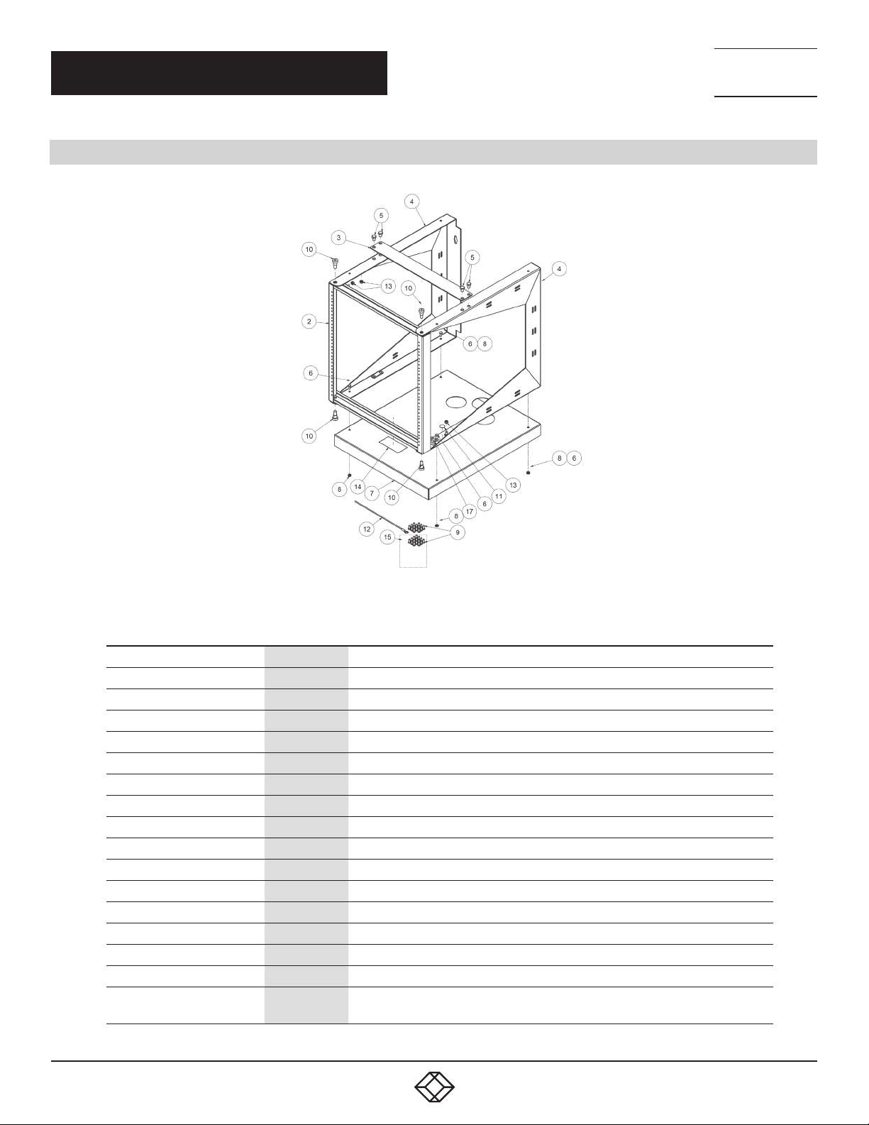
FIGURE 1-1. RM050A-R3
TABLE 1-3. RM050A-R3 COMPONENTS
NUMBER IN FIGURE 1-1 QUANTITY DESCRIPTION
2 1 21.313" H reinforced swing frame, weldment
3 1 Top/bottom brace
4 2 21.633" H x 25" D swing rack side — weldment
5 4 Bolt 3/8"-16 X 1/2" hex head or 2 RBZ
6 4 Bolt 1/4-20 x 1/2" L hex head
7 1 Swing rack base plate
8 4 Nut, 1/4-20, steel, grade 2, RBZ
9 30 Screw 12-24 x 1/2" L PPH T23 RBZ (equipment installation)
10 4 Screw socket head 3/8"-16 plain
11 1 Ground label, 1/2" dia., ED & D, SL-01
12 1 Ground wire, 11"L (stripped)
13 4 Nut M6 kepps tooth nut RBZ
14 1 Labels UL
15 1 Bag, 3 x 5 orange, heat seal with hardware “DO NOT DISCARD"
16 1 Black Box Ultra Wallmount Racks User’s manual
17 1
2S2/0" 2/0-14 AWG, and flex wire G-K w/mm2 class 5, 2 barrel, aluminum
or copper wire, CU9AL, 90C temp. single 1/4 bit mnt, UL and CSA
1. 87 7. 8 7 7. 2 26 9 BLACK BOX .COM
5
Page 6
CHAPTER 1: SPECIFICATIONS
NEED HELP?
LEAV E TH E TEC H TO US
LIVE 24/7
TECHNICAL
SUPPORT
1. 8 7 7. 8 7 7. 2 2 69
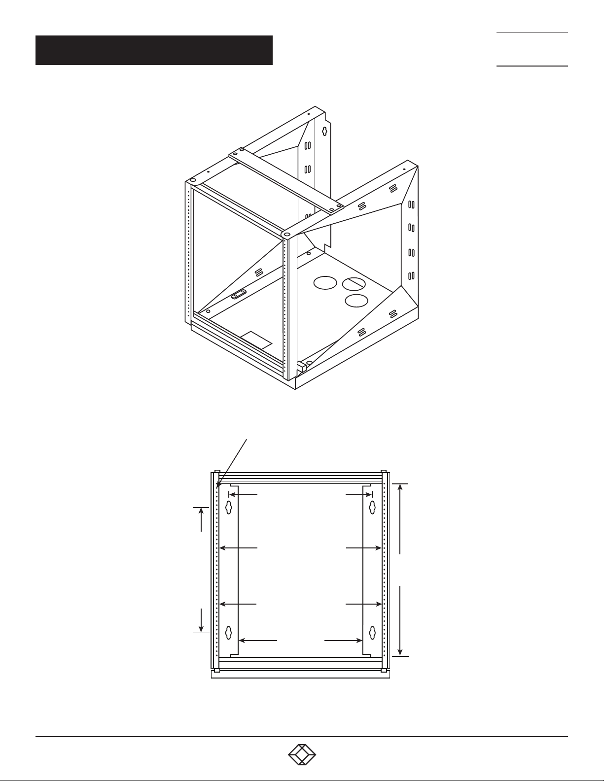
FIGURE 1-2. RM050A-R3 ASSEMBLED VIEW
Tapped #12-24 UNC-2B (11 RU)
16.00 CENTERS
17.81 OPENING
14.00 CENTERS
18.313 TO E.I. A.
13.8 8
19.31
FIGURE 1-3. RM050A-R3 FRONT VIEW
6
1. 87 7. 8 7 7. 2 26 9 BLACK BOX .COM
Page 7
CHAPTER 1: SPECIFICATIONS
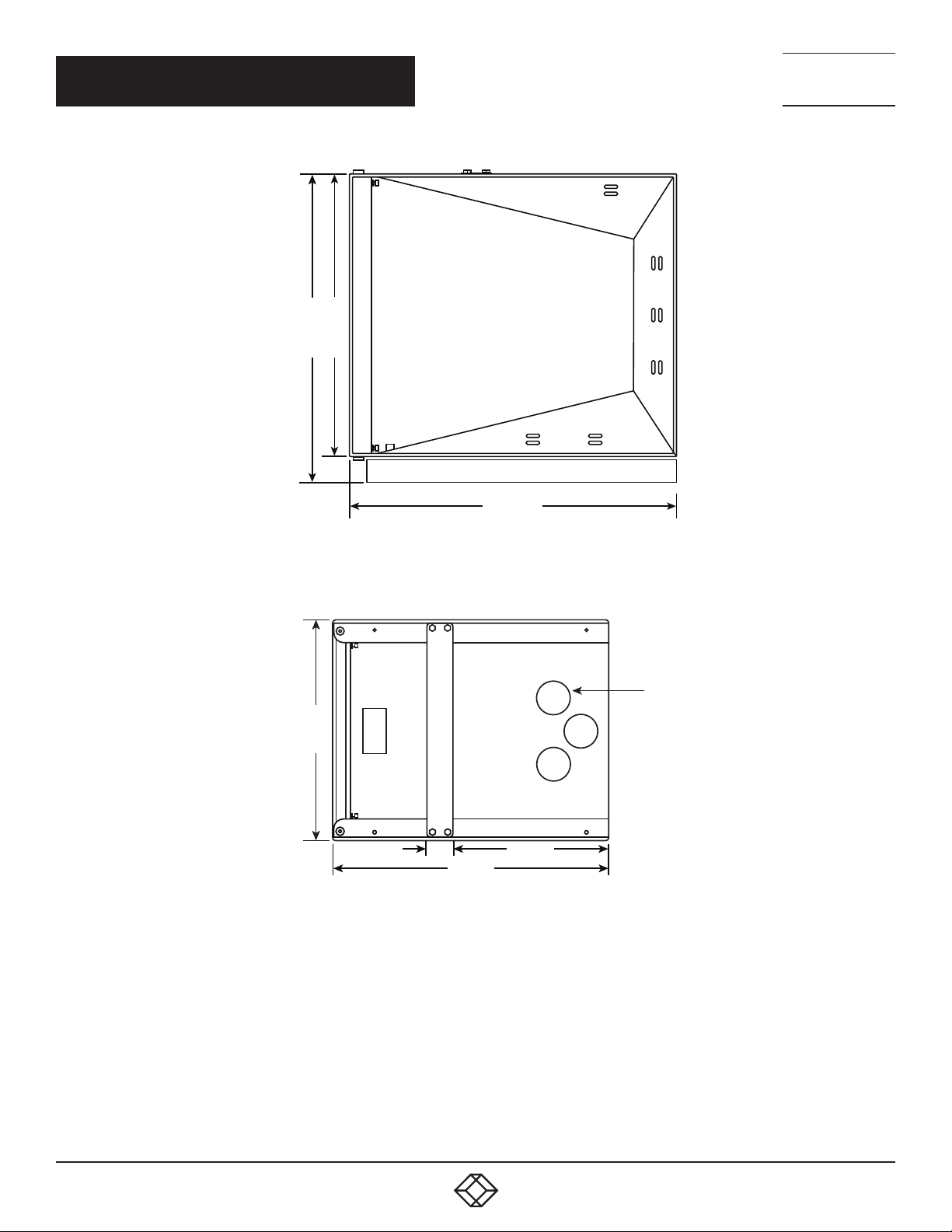
21.6 3
23.63
NEED HELP?
LEAV E TH E TEC H TO US
LIVE 24/7
TECHNICAL
SUPPORT
1. 8 7 7. 8 7 7. 2 2 69
25.00
FIGURE 1-4. RM050A-R3 RIGHT SIDE VIEW
19.8 8
2.31
25.00
14.16
FIGURE 1-5. RM050A-R3 TOP VIEW
2X 3.00
1. 87 7. 8 7 7. 2 26 9 BLACK BOX .COM
7
Page 8
CHAPTER 1: SPECIFICATIONS
1.4 RM051A-R3 DRAWINGS
NEED HELP?
LEAV E TH E TEC H TO US
LIVE 24/7
TECHNICAL
SUPPORT
1. 8 7 7. 8 7 7. 2 2 69
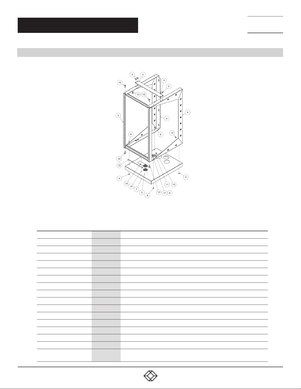
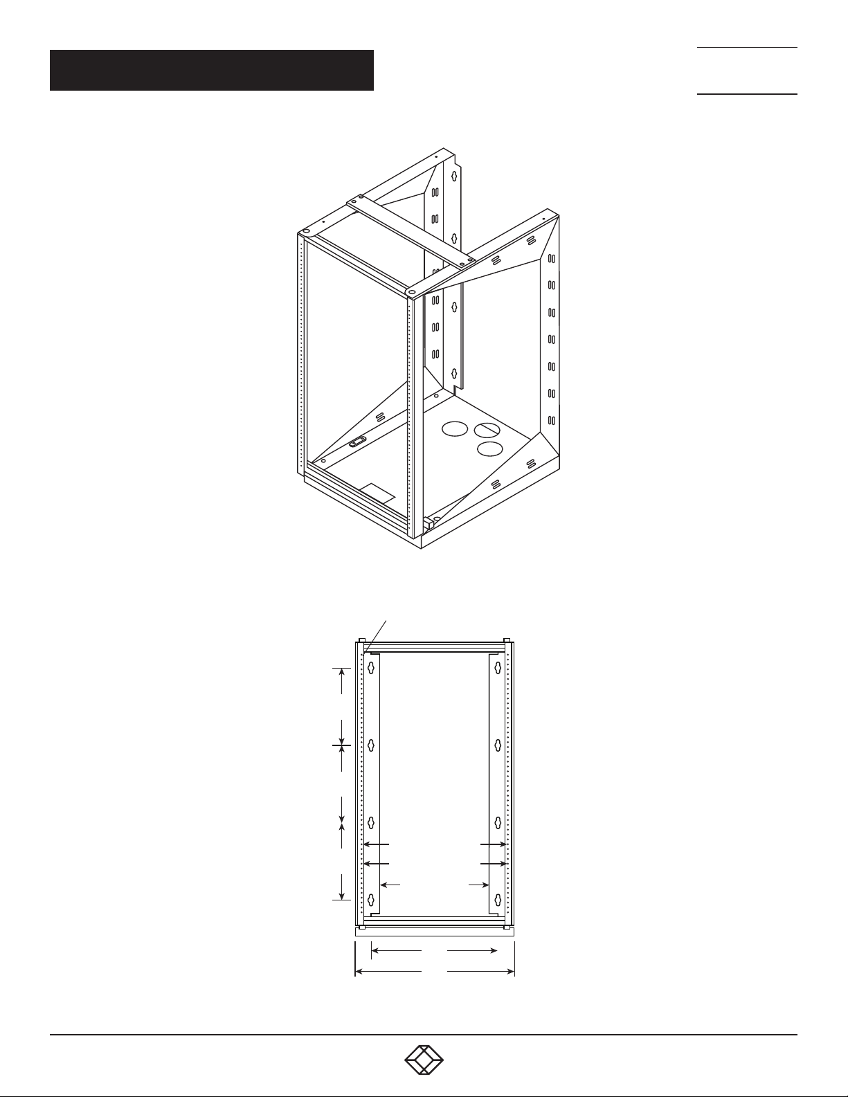
FIGURE 1-6. RM051A-R3
TABLE 1-4. RM051A-R3 COMPONENTS
NUMBER IN FIGURE 1-6 QUANTITY DESCRIPTION
2 1 35.313" H reinforced swing frame, weldment
3 1 Top/bottom brace
4 2 35.633" H x 25" D swing rack side — weldment
5 4 Bolt 3/8"-16 X 1/2" hex head or 2 RBZ
6 4 Bolt 1/4-20 x 1/2" L hex head
7 1 Swing rack base plate
8 4 Nut, 1/4-20, steel, grade 2, RBZ
9 50 Screw 12-24 x 1/2" L PPH T23 RBZ (equipment installation)
10 4 Screw socket head 3/8"-16 plain
11 1 Ground label, 1/2" dia., ED & D, SL-01
12 1 Ground wire, 11"L (stripped)
13 4 Nut M6 kepps tooth nut RBZ
14 1 Labels UL
15 1 Bag, 3 x 5 orange, heat seal with hardware “DO NOT DISCARD"
16 (not pictured) 1 Black Box Ultra Wallmount Racks User’s manual
17 1
2S2/0" 2/0-14 AWG, and flex wire G-K w/mm2 class 5, 2 barrel, aluminum
or copper wire, CU9AL, 90C temp. single 1/4 bit mnt, UL and CSA
8
1. 87 7. 8 7 7. 2 26 9 BLACK BOX .COM
Page 9
CHAPTER 1: SPECIFICATIONS
NEED HELP?
LEAV E TH E TEC H TO US
LIVE 24/7
TECHNICAL
SUPPORT
1. 8 7 7. 8 7 7. 2 2 69
FIGURE 1-7. RM051A-R3 ASSEMBLED VIEW
Tapped #12-24 UNC-2B (19 RU)
9.753
9.753
18.313 TO E.I. A.
9.753
17.81 OPENING
13.88 INSIDE
16.000
MTG HOLES
19.8 8
FIGURE 1-8. RM051A-R3 FRONT VIEW
1. 87 7. 8 7 7. 2 26 9 BLACK BOX .COM
9
Page 10
CHAPTER 1: SPECIFICATIONS
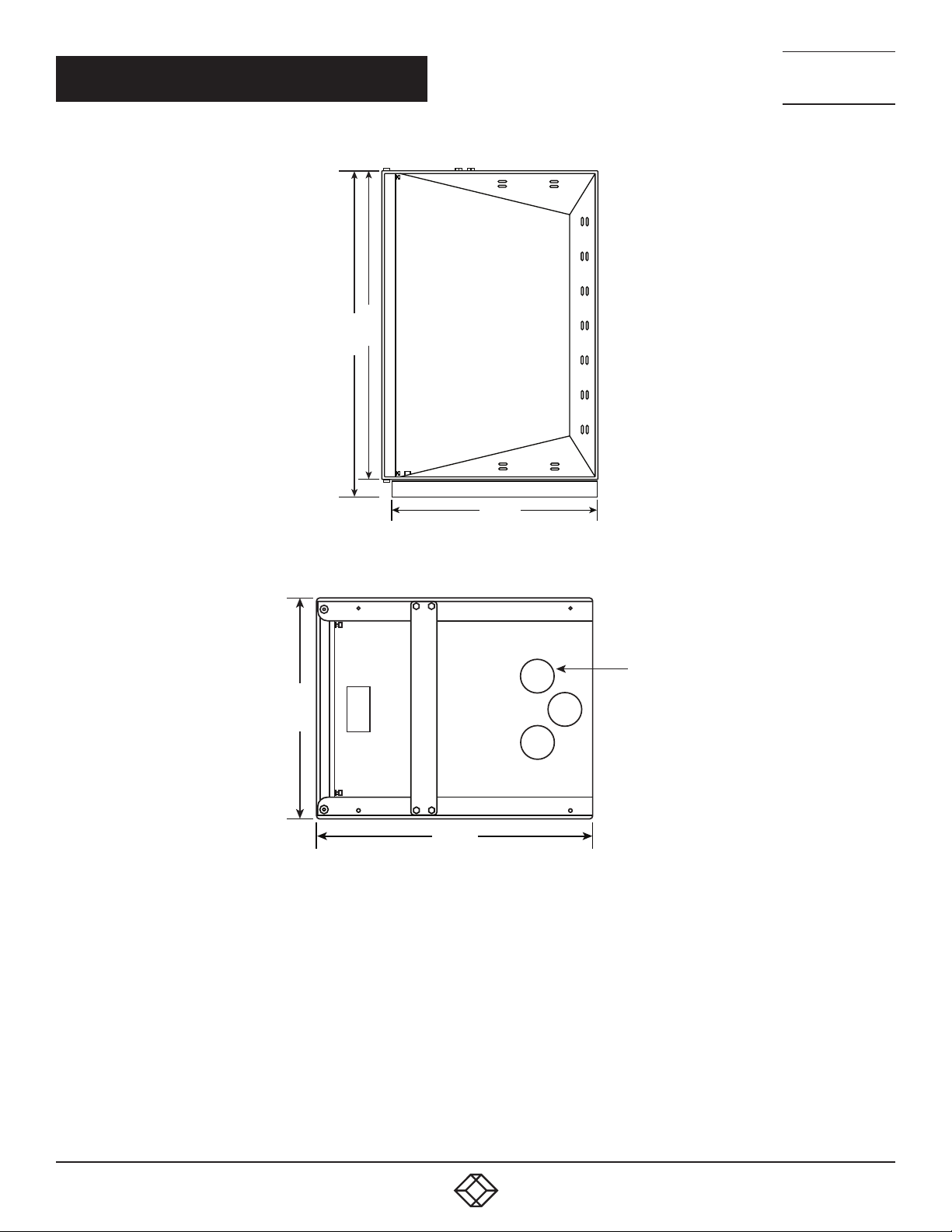
35.63
37. 63
NEED HELP?
LEAV E TH E TEC H TO US
LIVE 24/7
TECHNICAL
SUPPORT
1. 8 7 7. 8 7 7. 2 2 69
25.00
FIGURE 1-9. RM051A-R3 RIGHT SIDE VIEW
19.8 8
25.00
FIGURE 1-10. RM051A-R3 TOP VIEW
2X 3.00
10
1. 87 7. 8 7 7. 2 26 9 BLACK BOX .COM
Page 11
NEED HELP?
LEAV E TH E TEC H TO US
LIVE 24/7
CHAPTER 2: OVERVIEW
2.1 INTRODUCTION
Ultra Wallmount Racks are designed to securely hold 19” rackmount equipment, networking equipment, phone
equipment, etc. in tight spaces or closets.
TECHNICAL
SUPPORT
1. 8 7 7. 8 7 7. 2 2 69
2.2 FEATURES
25" depth provides plenty of rooom to open and close the rack, even when fully loaded with patch panels, hubs, or routers.
Reinforcement base plate.
Welded steel frame.
Can be reversed to open left or right.
2.3 WHAT’S INCLUDED
Your package should include the following items. If anything is missing or damaged, please contact Black Box Technical Support
at 877-877-2269 or [email protected].
Swing rack base plate
Top/bottom brace
3
(4)
⁄8”-16 x 1⁄2” hex head bolts, black
(4) socket head shoulder set screws
1
(4)
⁄4”-20” x 1⁄2” hex head screws
1
(4)
⁄4”-20” keps nuts with external tooth lock washer
(2) swing rack sides
(1) swing frame
(30) 12-24 mounting screws
Bonding and grounding system with (1) ground jumper
2.4 SERVICE
The Ultra Wallmount Rack should be repaired by personnel trained by Black Box, or returned to Black Box for repair
or replacement. Contact Black Box Technical Support at 877-877-2269 or [email protected]
1. 87 7. 8 7 7. 2 26 9 BLACK BOX .COM
11
Page 12
NEED HELP?
LEAV E TH E TEC H TO US
LIVE 24/7
CHAPTER 3: MOUNTING INSTRUCTIONS
3.1 RECEIVING, UNPACKING AND REMOVING THE RACK FROM THE CARTON
Inspect for damage and report damage if there is damage before receiving. Refer to Section 2.3 for what‘s included
in the package.
Unpack the rack by carefully removing the corrugated carton and corners. Avoid damaging the enclosure when removing
packaging.
WARNING: Only trained service personnel should be used to remove the rack from the carton. Also be sure you have
a sufficient number of service personnel. Do not attempt to move racks by yourself.
TECHNICAL
SUPPORT
1. 8 7 7. 8 7 7. 2 2 69
WARNING: Be careful when moving racks before installation. Sudden stops and starts, excessive force, obstructed routes,
and uneven floor surfaces may cause the rack to topple over.
3.2 WOOD STUDDED WALL
Once the location on the wall has been determined, inspect the wall surface. The wall must be flat and square in the horizontal and
vertical plane to ensure the Ultra Wallmount Rack closes correctly. If the wall is not flat and square, you might need to use shims.
Wood studded wall mounting instructions apply to a 2” x 4” wood stud wall with ¾” plywood.
You can mount the back section to the wall and secure it with
WARNING: Improper handling and use of the Ultra Wallmount Rack could result in equipment damage, serious injury,
or possible death.
3.3 MASONRY WALL SURFACE
For a masonry wall surface, the installer must provide the appropriate hardware.
3
⁄8”-2” lag bolts (not included) and washers (not included).
12
1. 87 7. 8 7 7. 2 26 9 BLACK BOX .COM
Page 13
NEED HELP?
LEAV E TH E TEC H TO US
LIVE 24/7
CHAPTER 3: MOUNTING INSTRUCTIONS
TECHNICAL
SUPPORT
1. 8 7 7. 8 7 7. 2 2 69
3.4 LOADING EQUIPMENT
WARNING: Only install equipment after the Ultra Wallmount Rack has been properly secured and mounted to the wall.
Maximum Load Capacity
The rated or maximum load capacity for the RM050A-R3 is 75 pounds, and the maximum load capacity for the RM051A-R3
is 100 pounds. To maintain uniform distribution of the mechanical load in the rack, load the heaviest equipment first at the bottom
and the lighter units at the top.
3.5 POWER
When using power distribution units (PDUs), each PDU should be connected to a committed branch circuit that is rated
for the continuous load of all the connected equipment.
When not using a PDU, each piece of equipment should be connected to a dedicated branch circuit.
3.6 PROTECTIVE GROUNDING
A main protective grounding stud and grounding studs are provided along with grounding jumper wires that electrically bond
the swing frame doors to one of the swing rack sides.
WARNING: To avoid injury to persons or loss of life, ground each enclosure individually to the dedicated branch circuit earthing ground.
3.6.1 CONNECTING MAIN PROTECTIVE GROUNDING STUD TO THE DEDICATED BRANCH CIRCUIT
GROUNDING CONDUCTOR
Connect the dedicated branch circuit ground conductor to the main protective grounding stud located at the rear of one
of the swing rack sides.
3.6.2 CONNECTING MAIN PROTECTIVE GROUNDING STUD TO THE PROTECTIVE BONDING CONDUCTORS
Connect the swing frame to the grounding stud located at the front of one swing rack side using a listed ring or closed-loop
terminal.
1. 87 7. 8 7 7. 2 26 9 BLACK BOX .COM
13
Page 14
CHAPTER 3: MOUNTING INSTRUCTIONS
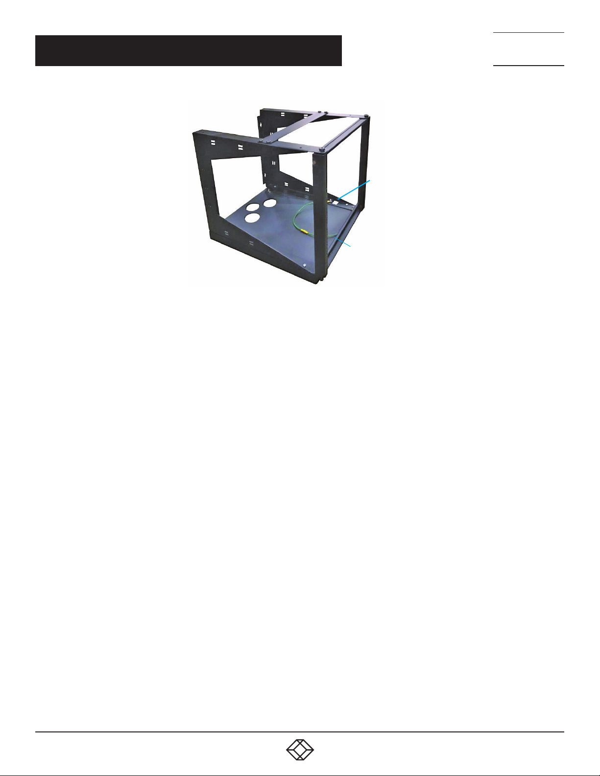
FIGURE 3-1. ULTRA WALLMOUNT RACK WITH JUMPER WIRE AND GROUND STUDS
Ground stud
Jumper wire
NEED HELP?
LEAV E TH E TEC H TO US
LIVE 24/7
TECHNICAL
SUPPORT
1. 8 7 7. 8 7 7. 2 2 69
14
1. 87 7. 8 7 7. 2 26 9 BLACK BOX .COM
Page 15

NEED HELP?
LEAV E TH E TEC H TO US
LIVE 24/7
APPENDIX: DISCLAIMER/TRADEMARKS
TECHNICAL
SUPPORT
1. 8 7 7. 8 7 7. 2 2 69
A.1 DISCLAIMER
Black Box Corporation shall not be liable for damages of any kind, including, but not limited to, punitive, consequential or cost of cover
damages, resulting from any errors in the product information or specifications set forth in this document and Black Box Corporation
may revise this document at any time without notice.
A.2 TRADEMARKS USED IN THIS MANUAL
Black Box and the Black Box logo type and mark are registered trademarks of Black Box Corporation.
Any other trademarks mentioned in this manual are acknowledged to be the property of the trademark owners.
1. 87 7. 8 7 7. 2 26 9 BLACK BOX .COM
rm050a-r3_rm051a-r3_user_rev4.pdf
15
Page 16

NEED HELP?
LEAVE THE TECH TO US
LIVE 24/7
TECHNICAL
SUPPORT
1.87 7. 8 7 7.2269
© COPYRIGHT 2017 BLACK BOX CORPORATION. ALL RIGHTS RESERVED.
 Loading...