

Page 1

© Copyright 2006. Black Box Corporation. All rights reserved.
1000 Park Drive · Lawrence, PA 15055-1018 · 724-746-5500 ·
Fax 724-746-0746
ServPower Omni
OCTOBER 2007
PS730A
PS730A-M
PS731A
PS731A-M
PS732A
PS732A-M
PS733A
PS733A-M
PSE711
PSE712
PSE713
PSE714
PSE721
PSE722
PSE723
PSE724
Order toll-free in the U.S.: 877-877-BBOX (outside U.S. call 724-746-5500)
FREE technical support, 24 hours a day, 7 days a week: Call 724-746-5500 or fax 724-746-0746
Mail order: Black Box Corporation, 1000 Park Drive, Lawrence, PA 15055-1018
Web site: www.blackbox.com • E-mail: info@blackbox.com
CUSTOMER
SUPPORT
INFORMATION
Page 2

37
Page 3

ServPower Omni
36
Philippines 181
Portugal 253
Slovak Republic 253
Spain 253
Sweden 253
Switzerland 253
Taiwan 254
United Kingdom 253
United States 181
FCC STATEMENT
1
FEDERAL COMMUNICATIONS COMMISSION
AND
CANADIAN DEPARTMENT OF COMMUNICATIONS
RADIO FREQUENCY INTERFERENCE STATEMENTS
This equipment generates, uses, and can radiate radio frequency energy
and if not installed and used properly, that is, in strict accordance with
the manufacturer’s instructions, may cause interference to radio
communication. It has been tested and found to comply with the limits
for a Class A computing device in accordance with the specifications in
Subpart B of Part 15 of FCC rules, which are designed to provide
reasonable protection against such interference when the equipment is
operated in a commercial environment. Operation of this equipment in a
residential area is likely to cause interference, in which case the user at
his own expense will be required to take whatever measures may be
necessary to correct the interference.
Changes or modifications not expressly approved by the party
responsible for compliance could void the user’s authority to operate the
equipment.
This digital apparatus does not exceed the Class A limits for radio noise
emission from digital apparatus set out in the Radio Interference
Regulation of the Canadian Department of Communications.
Le présent appareil numérique n’émet pas de bruits radioélectriques
dépassant les limites applicables aux appareils numériques de la classe
A prescrites dans le Règlement sur le brouillage radioélectrique publié
par le ministère des Communications du Canada.
Page 4

ServPower Omni
2
Normas Oficiales Mexicanas (NOM)
Electrical Safety Statement
INSTRUCCIONES DE SEGURIDAD
1. Todas las instrucciones de seguridad y operación deberán ser leídas
antes de que el aparato eléctrico sea operado.
2. Las instrucciones de seguridad y operación deberán ser guardadas para
referencia futura.
3. Todas las advertencias en el aparato eléctrico y en sus instrucciones de
operación deben ser respetadas.
4. Todas las instrucciones de operación y uso deben ser seguidas.
5. El aparato eléctrico no deberá ser usado cerca del agua—por ejemplo,
cerca de la tina de baño, lavabo, sótano mojado o cerca de una alberca,
etc.
6. El aparato eléctrico debe ser usado únicamente con carritos o
pedestales que sean recomendados por el fabricante.
7. El aparato eléctrico debe ser montado a la pared o al techo sólo como
sea recomendado por el fabricante.
8. Servicio—El usuario no debe intentar dar servicio al equipo eléctrico
más allá a lo descrito en las instrucciones de operación. Todo otro
servicio deberá ser referido a personal de servicio calificado.
9. El aparato eléctrico debe ser situado de tal manera que su posición no
interfiera su uso. La colocación del aparato eléctrico sobre una cama,
sofá, alfombra o superficie similar puede bloquea la ventilación, no se
debe colocar en libreros o gabinetes que impidan el flujo de aire por
los orificios de ventilación.
10. El equipo eléctrico deber ser situado fuera del alcance de fuentes de
calor como radiadores, registros de calor, estufas u otros aparatos
(incluyendo amplificadores) que producen calor.
Appendix B: Modem Certifications
35
Modem Certifications
The following countries have certified the internal modem. In order
to comply with local regulations, the countrycode must be set to the
country of installation. To set the modem for the desired country use
the CLI command
set modem countrycode <countrycode>. Use the
get modem command to display the current country setting.
Note: Use of the wrong countrycode violates local laws and the warranty of this
product.
Country countrycode
Argentina 07
Australia 09
Austria 253
Belgium 253
Canada 181
China 181
Cyprus 253
Czech Republic 253
Denmark 253
Finland 253
France 253
Germany 253
Greece 253
Hong Kong 153
Hungary 253
Iceland 253
Indonesia 153
Ireland 253
Italy 253
Japan 00
Korea 181
Liechtenstein 253
Luxembourg 253
Mexico 181
Netherlands 253
New Zealand 126
Norway 253
Page 5

ServPower Omni
34
PSE723 2 x C20 8 x C13 I, S
PSE724 2 x C20 8 x C13 I, S, M
Key:
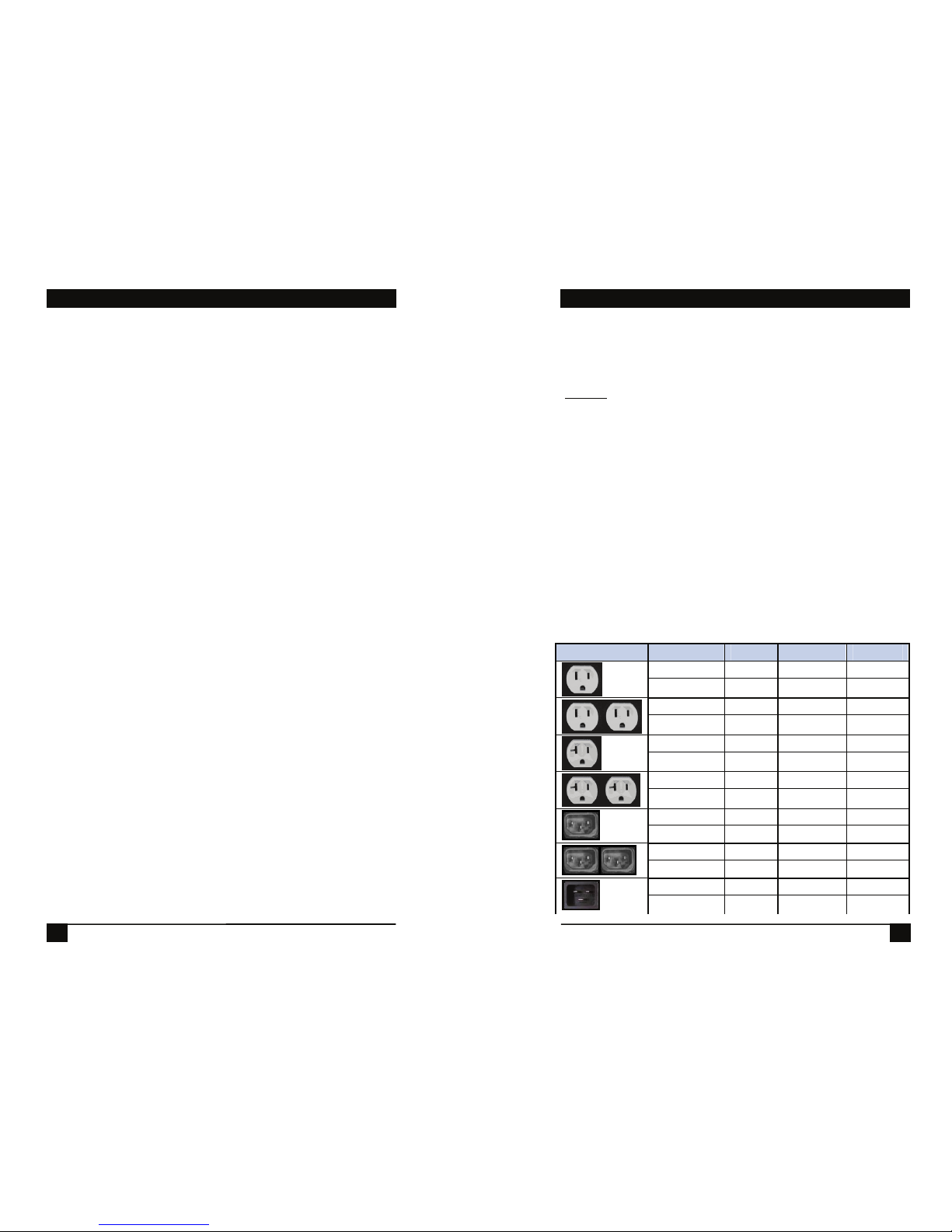
INPUT:
N15 NEMA 5-15 Linecord 115VAC 15 Amps combined total
switched
N20 NEMA 5-20 Linecord 115VAC 20 Amps combined total
switched
C14 IEC320 C14 Receptacle 100-240VAC 10 Amps total at 240VAC
Max
C20 IEC320 C20 Receptacle 100-240VAC 20 Amps total at 240VAC
Max
O
UTLET:
N15 NEMA 5-15 Receptacle 115VAC 12 Amps Max
C13 IEC 320 C13 Receptacle 100-240VAC 10 Amps Max
C
ONTROL:
I 10/100 Ethernet. Web, Telnet, SNMP. Port Assignable for Web
and Telnet. SSL on Web control.
S Serial Port. 115,200 bps. Command Line Interface
M Internal Modem. V.92 and below. Approved in 50 Countries
Supports data and DTMF tone control (with voice response)
NOM STATEMENT
3
11. El aparato eléctrico deberá ser connectado a una fuente de poder sólo
del tipo descrito en el instructivo de operación, o como se indique en
el aparato.
12. Precaución debe ser tomada de tal manera que la tierra fisica y la
polarización del equipo no sea eliminada.
13. Los cables de la fuente de poder deben ser guiados de tal manera que
no sean pisados ni pellizcados por objetos colocados sobre o contra
ellos, poniendo particular atención a los contactos y receptáculos
donde salen del aparato.
14. El equipo eléctrico debe ser limpiado únicamente de acuerdo a las
recomendaciones del fabricante.
15. En caso de existir, una antena externa deberá ser localizada lejos de
las lineas de energia.
16. El cable de corriente deberá ser desconectado del cuando el equipo no
sea usado por un largo periodo de tiempo.
17. Cuidado debe ser tomado de tal manera que objectos liquidos no sean
derramados sobre la cubierta u orificios de ventilación.
18. Servicio por personal calificado deberá ser provisto cuando:
A: El cable de poder o el contacto ha sido dañado; u
B: Objectos han caído o líquido ha sido derramado dentro del aparato;
o
C: El aparato ha sido expuesto a la lluvia; o
D: El aparato parece no operar normalmente o muestra un cambio en
su desempeño; o
E: El aparato ha sido tirado o su cubierta ha sido dañada.
Page 6
ServPower Omni
4
Appendix A: Specifications
33
Specifications
Physical:
Height: 1U 1.75 in (4.5 cm)
Width: 19.0 in (48.25 cm)
Depth: 6.00 in (15.25 cm)
Weight: 7 lbs (3.25 Kg)
Input Required Model Input Output Control
PS730A N15 8 x N15 I, S,
PS730A-M N15 8 x N15 I, S, M
PS731A 2 x N15 8 x N15 I, S, L
PS731A-M 2 x N15 8 x N15 I, S, M
PS732A N20 8 x N15 I, S
PS732A-M N20 8 x N15 I, S, M
PS733A 2 x N20 8 x N15 I, S
PS733A-M 2 x N20 8 x N15 I, S, M
PSE711 C14 8 x C13 I, S
PSE712 C14 8 x C13 I, S, M
PSE721 2 x C14 8 x C13 I, S
PSE722 2 x C14 8 x C13 I, S, M
PSE713 C20 8 x C13 I, S
PSE714 C20 8 x C13 I, S, M
Temperature
Operating: 0 to 40
o
C
Storage: -10 to 85
o
C
Relative
Humidity
0 to 95%
Non-Condensing
Page 7

ServPower Omni
32
|
-> [ 1] *RO* Integer32 .............................................. currentLC1
-> [ 2] *RO* Integer32 .............................................. currentLC2
-> [ 3] *RO* INTEGER(Enum) ..................numberOfLineCords
|
-> [ 5] -NT- outletChange
-> [ 6] -NT- autoPingFailed
-> [ 7] -NT- newNotifTyp01
Legend :
AC - Agent Capabilities
AN - Accessible for Notify
BR - Branch
MC - Module Compliance
MI - Module Identity
NA - Not Accessible
NG - Notification Group
NT - Notification Type
OG - Object Group
OI - Object Identity
RO - Read Only
RC - Read Create
RW - Read Write
TB - Table
TE - Table Entry
7.7 Firmware Upgrades
The ServPower Omni can be upgraded via the network if the upload
feature has been enabled using the set upload enable yes command on the
console interface. To upgrade the ServPower Omni contact BlackBox
Technical Support.
7.8 Password Recovery
Holding the reset button on the front panel of the ServPower Omni for 5
seconds or longer will initiate a password recovery mode. Once the reset
button is released, the user has 30 seconds to log in to the CLI using the
username admin and password admin. Upon accessing the CLI, change
the username and password for User 1 as desired.
CONTENTS
5
Contents
1. QUICK START ............................................................................... 7
1.1 DEFAULT IP ADDRESS. ............................................................. 7
1.2 DEFAULT USER CREDENTIALS...................................................... 7
2. GENERAL OVERVIEW................................................................ 8
3. INSTALLATION ............................................................................ 9
3.1 RACK MOUNTING ......................................................................... 9
3.2 ETHERNET .................................................................................... 9
3.3 SERIAL PORT .............................................................................. 10
3.4 DIAL LINE................................................................................... 10
3.5 EXPANSION................................................................................. 11
3.6 POWER SOURCE .......................................................................... 11
4. INITIAL CONFIGURATION...................................................... 13
4.1 ACCESSING THE COMMAND LINE INTERFACE ............................. 13
4.2 SETTING THE IP ADDRESS.......................................................... 13
5. WEB OPERATION....................................................................... 16
5.1 WEB INTERFACE ......................................................................... 16
5.2 OUTLET CONTROL ......................................................................17
5.3 USER PRIVILEGES ....................................................................... 17
5.4 GROUPING OUTLETS................................................................... 17
6. CLI OPERATION......................................................................... 18
6.1 COMMAND LINE INTERFACE....................................................... 18
6.3 DEVICE COMMANDS ...................................................................19
6.3 OUTLET COMMANDS .................................................................. 21
6.4 NETWORK COMMANDS............................................................... 22
6.5 USER COMMANDS....................................................................... 25
6.6 GROUP COMMANDS .................................................................... 26
7. ADVANCED FEATURES............................................................ 27
7.1 DTMF CONTROL........................................................................ 27
7.2 DTMF CALL SEQUENCE:............................................................ 27
7.3 AUTOPING ..................................................................................28
7.4 SSL ............................................................................................ 29
7.5 EMAIL NOTIFICATION .................................................................30
Page 8

ServPower Omni
6
7.6
SNMP......................................................................................... 30
7.7 FIRMWARE UPGRADES ................................................................32
7.8 PASSWORD RECOVERY................................................................32
APPENDIX
A. SPECIFICATIONS.......................................................................33
B. MODEM CERTIFICATIONS.....................................................35
CHAPTER 7: Advanced Features
31
SNMP MIB
Download at BlackBox\ServPower_Omnitools.html
enterprises [1.3.6.1.4.1] |
-> [1418] -MI- blackbox
|
-> [ 4] -BR- ServPower OmniAgent
|
-> [ 1] -BR- systemSettings
|
-> [ 1] *RW* DisplayString .....................................deviceName
-> [ 2] *RW* INTEGER(Enum) ..................................... ipMode
-> [ 3] *RW* DisplayString .........................................ipAddress
-> [ 4] *RW* DisplayString ..................................... subnetMask
-> [ 5] *RW* DisplayString ........................................... gateway
-> [ 6] *RW* INTEGER(Enum) ................................webEnable
-> [ 7] *RW* Integer32 .................................................. webPort
-> [ 8] *RW* INTEGER(Enum) .................................. sslEnable
-> [ 9] *RW* INTEGER(Enum) ..............................telnetEnable
-> [10] *RW* Integer32 ............................................... telnetPort
-> [11] *RW* INTEGER(Enum) ........................... updateEnable
-> [12] *RW* Integer32 .............................................. cycleTime
-> [13] *RW* Integer32 ..............................................delayTime
|
-> [ 2] -TB- snmpManagerTable
|
-> [ 1] -TE- snmpManagerEntry
|
-> [ 1] *RO* Integer32 .............................snmpManagerIndex
-> [ 2] *RW* DisplayString ..............snmpManagerIPAddress
-> [ 3] *RW* INTEGER(Enum) ............ snmpManagerEnable
|
-> [ 3] -TB- outletTable
|
-> [ 1] -TE- outletEntry
|
-> [ 1] *RO* Integer32 ...........................................outletIndex
-> [ 2] *RW* OCTET STRING ............................ outletName
-> [ 3] *RO* INTEGER(Enum) ............................outletStatus
-> [ 4] *RW* INTEGER(Enum) .................... outletCommand
-> [ 5] *RO* INTEGER(Enum) .......................outletAPStatus
|
-> [ 4] -BR- info
Page 9

ServPower Omni
30
The ServPower Omni can provide Secure Socket Layer (SSL) encryption
on the web interface. Enable this feature using the set web ssl yes
command from the Telnet / Serial interface.
7.5 Email Notification
Email can be automatically sent for outlet changes, AutoPing triggers and
current alarms. The necessary parameters for email are set using the
Telnet / Serial Interface:
set email server <dotted decimal>
set email address <return address 64 char max>
set email username <user name 128 char max>
set email password <password 128 char max>
Each user is assigned an email address and email can be turned on or off
for that user:
set user <name> email <email address 64 char max>
set user <name> sendmail <yes/no>
7.6 SNMP
Up to four SNMP managers can be set. Each manager will receive Trap
notifications for outlet changes, autoping and current alarms. Set the
SNMP manager IP addresses using the
set snmp <n> ipaddress
<dotted decimal>
command. Enable or Disable SNMP for any
manager with the
set snmp <n> enable <yes/no> command.
CHAPTER 1: Quick Start
7
1. Quick Start
1.1 Default IP address 192.168.0.254
1.2 Default User Credentials
Username: admin
Password: admin
Serial Port
Network
Page 10

ServPower Omni
8
2. General Overview
The ServPower Omni series is designed to provide power distribution and
remote power control. Each ServPower Omni allows eight outlets to be
independently switched on and off for reboot, energy management and
security. The ServPower Omni has many features to make the
management of power distribution simple and cost effective:
• 8 independently controllable outlets
• Dual power inputs for redundant power feeds
• Support for dual redundant powered devices
• Naming of outlets for easy identification
• Grouping of outlets for simultaneous management
• Current monitoring with over and under alarm notification
• Multiple users with assigned rights and simultaneous control
• Web Browser Control
• Telnet/Serial CLI control
• Direct UDP via SNMP control
• SNMP manageable
• AutoPing for automatic reboot of crashed systems
• SSL Security (web only)
• Internal Modem Option, Data or DTMF Control
CHAPTER 7: Advanced Features
29
ACTION: Select from
None AutoPing not used
On – Latch Upon triggering, ServPower Omni will power on
the assigned outlet and remain so until changed via
the web or telnet/serial interface.
On – Follow Upon triggering, ServPower Omni will power on
the assigned outlet. When the ping response
returns, ServPower Omni will power the off the
outlet
Off – Latch Upon triggering, ServPower Omni will power off
the assigned outlet and remain so until changed via
the web or telnet/serial interface.
Off – Follow Upon triggering, ServPower Omni will power off
the assigned outlet. When the ping response
returns, ServPower Omni will power the outlet on.
Cycle Upon triggering, ServPower Omni will cycle the
power to the assigned outlet. ServPower Omni will
wait the Ping Frequency x Fail Count; if the
response does not return, the power will be recycled
again. This will continue until the ping response
returns or AutoPing is turned off. Make sure your
AutoPing frequency x Fail Count is longer than the
time required to reboot your device.
Cycle Once Upon triggering, ServPower Omni will cycle power
one time. It will not cycle again automatically until
the ping response returns and is lost again.
With AutoPing operational, the ServPower Omni page will display the
current status of this feature. The status will be OK to indicate that
ServPower Omni is receiving responses to the ping, or that the fail counter
has not yet been exceeded. Click on the Status message to see greater
details on the AutoPing status.
If the fail count has been exceeded, the status will change to Triggered.
Click on the Status message to see greater details on the AutoPing status.
7.4 SSL
Page 11

ServPower Omni
28
Notes:
Not issuing a command for 5 seconds will cause the ServPower Omni to hang
up.
The only outlets that a caller has access to are determined by the CLI command
set user outlet.
While prompts and voice responses are being played, the ServPower Omni will
not process DTMF tones. Wait for the status and prompts to complete before
issuing new commands
Address an outlet with a number command before entering a control command
(# or *) if unsure which outlet is being addressed, send the outlet number again.
Factory Default user admin has default PIN 23646. Change to desired PIN if
maintaining this account. Resetting to factory defaults will restore this user and
PIN.
7.3 AutoPing
The AutoPing feature allows ServPower Omni to automatically detect
failed equipment and perform a timed reboot or other power control
function (like turning on an indicator or siren). You set any IP address to
be periodically pinged. When ServPower Omni no longer detects a
response from the address, the programmed power control function is
actuated.
Up to eight IP addresses can be monitored by AutoPing. Each AutoPing
monitor is assigned to an outlet.
P
ING ADDRESS Enter the IP address of the device to be pinged.
P
ING FREQUENCY Enter 1 to 999 seconds. The ping will go out to the
selected device this often.
F
AIL COUNTER Enter 1-99 times the ping needs to fail consecutively
before the selected action is taken. When the fail count has been reached,
the AutoPing action will be triggered.
CHAPTER 3: Installation
9
3. Installation
3.1 Rack Mounting
The ServPower Omni is designed for mounting in a standard 19”
equipment cabinet.
There are two L-shape brackets marked as “L” and “R”, install the “L”
bracket on the left side of the ServPower Omni chassis then the “R”
bracket on its right side.
Install the ServPower Omni to the standard 19-inch rack.
3.2 Ethernet
The ServPower Omni has a 10/100 Ethernet port. The default address is
192.168.0.254
Page 12

ServPower Omni
10
3.3 Serial Port
The ServPower Omni has a 9 pin D subminiature connector for RS-232
serial control. The connector is configured as DCE for direct connection
to a laptop or other terminal device. Default serial parameters are 115,200
bps, 8 data, no parity, 1 stop bit (115200,8,n,1).
Serial Port pinout:
Pin No Description
1 Data Carrier Detect
2 Receive Data
3 Transmit Data
4 Data Terminal Ready
5 Signal Ground
6 Data Set Ready
7 Request to Send
8 Clear to Send
9 Ring Indicator
3.4 Dial Line
The following models have an internal modem.
<ADD DOMESTIC MODELS HERE
PSE712, PSE714, PSE722, PSE724
This modem supports both data and DTMF control. The modem is
approved for use in 36 countries. See Appendix A for a list of approved
countries.
CHAPTER 7: Advanced Features
27
7. Advanced Features
7.1 DTMF Control
Models with an internal modem: PS730A-M, PS731A-M, PS732A-M,
PS733A-M, PSE712, PSE714, PSE722, PSE724, can be controlled from
dial up connections using handset dialing tones (touch tones). Use of
DTMF control requires a unique PIN number set for each user. This PIN
is set using the command line interface and must be 4 to 10 digits long.
Program a PIN code of 0 to disable a users ability to use DTMF control.
7.2 DTMF Call Sequence:
1. Dial the phone number connected to the ServPower Omni.
Upon connection a prompt tone will be heard.
2. Enter the PIN followed by the # key. Upon successful entry, a
ready tone will be heard. If no PIN or incorrect PIN is
received, an error tone and new prompt tone will be issued.
After three unsuccessful attempts, the ServPower Omni will
hang up.
3. At the ready tone, enter an outlet number 1-8. The current
status of that outlet will be stated in English: i.e. “one on” or
“six off”.
4. The # key is used to change the state of the outlet. The * key
is used to reboot (or power cycle) the outlet for the time
configured with the CLI command cycle time. The new status
of the outlet is stated. If the * key is used, the ServPower
Omni will also state ‘begin’ to indicate the reboot or cycle has
begun.
5. A new prompt tone will indicate that new commands can be
entered. While a reboot is in progress, additional outlets can
be addressed and commanded.
6. The caller can hang up at any time to disconnect the call. Any
reboots in progress will finish their cycle time as programmed.
Page 13

ServPower Omni
26
6.6 Group Commands
get groups
Returns a list of groups
get group <name>
Returns a list of outlets in a
group
set group <name>
<on/off/cycle>
Sets a group’s name
The following commands require
administrative rights
add group <name>
Adds a group
set group <name> outlet <n/all>
<yes/no>
Adds or Deletes an outlet to
a group
ren group <name> <newname>
Renames a group
del group <name>
Deletes a group
CHAPTER 3: Installation
11
3.5 Expansion
For future applications.
3.6 Power Source
The ServPower Omni models PS730A and PS730A-M provide a linecord
for connection to a 15 Amp 115VAC service. The total maximum current
load for all outlets on the ServPower Omni cannot exceed 12 Amps.
The ServPower Omni Models PS731A and PS731A provide two linecords
for connection to 15 Amp 115VAC services. The total maximum current
load for outlets on any linecord cannot exceed 12 Amps. Each linecord
distributes power to four outlets.
The ServPower Omni models PS732A and PS732A-M provide a linecord
for connection to a 20 Amp 115VAC service. The total maximum current
load for all outlets on the ServPower Omni cannot exceed 16 Amps.
The ServPower Omni models PS733A and PS733A-M provide two
linecords for connection to 20 Amp 115VAC services. The total
maximum current load for outlets on any linecord cannot exceed 16
Amps. Each linecord distributes power to four outlets.
The ServPower Omni models PS711 and PS712 provide an IEC 320
universal inlet for connecting a detachable power cord. A standard IEC to
CEE7 European cord set is supplied with the unit for use on 10 Amp
240VAC service*. The total maximum current load for all outlets cannot
exceed 12 Amps at 115VAC or 10 Amps when used at 240VAC.
The ServPower Omni models PS721 and PS722 provide two IEC 320
universal inlet for connecting a detachable power cord. A standard IEC to
CEE7 European cord set is supplied with the unit for use on 10 Amp
240VAC service*. The total maximum current load for outlets on any
linecord cannot exceed 12 Amps at 115VAC or 10 Amps when used at
240VAC. Each linecord distributes power to four outlets.
The ServPower Omni models PS713 and PS714 provide an IEC 320
universal inlet for connecting a detachable power cord. A standard IEC to
CEE7 European cord set is supplied with the unit for use on 16 Amp
240VAC service*. The total maximum current load for all outlets cannot
exceed 16 Amps.
Page 14

ServPower Omni
12
The ServPower Omni models PS723 and PS724 provide two IEC 320
universal inlet for connecting a detachable power cord. A standard IEC to
CEE7 European cord set is supplied with the unit for use on 16 Amp
240VAC service*. The total maximum current load for outlets on any
linecord cannot exceed 16. Each linecord distributes power to four
outlets.
* Power cords for other countries are available from your local source. If
a power cord with a different terminating plug is required, be sure it is
properly rated and meets all the required local electrical standards.
CHAPTER 7: Advanced Features
25
6.5 User Commands
The following commands require administrative rights
get users
Returns a list of users.
add user <name>
Adds a new user. the new
password is automatically
created to match the
<name>
get user <name>
Returns user <name>’s
rights and settings.
ren user <name> <newname>
Renames a user
del user <name>
Deletes a user.
set user <name> outlet <n/all>
<yes/no>
Sets a user’s rights to
control one or more outlets.
set user <name> group <group
name> <yes/no>
Sets a user’s rights to
control one or more groups.
set user <name> role
<admin/user>
Sets a user’s administrator
privileges.
set user <name> password
<newpass> <confirm>
Sets a user’s password.
(default is same as name)
set user <name> email <email
address 64 char max>
Sets a users email address.
set user <name> sendmail
<yes/no>
Enables or Disables a user’s
receipt of email
notifications.
set user <name> pin <pin/0>
4-10 digits for DTMF control
via modem. Each user’s pin
must be unique. Set to 0 to
clear DTMF control.
Page 15

ServPower Omni
24
set time zone <time zone -12 to
13>
set time hour <0-23>
set time minute <0-59>
set time day <1-31>
set time month <1-12>
set time year <2006-2047>
- Reboot is required for these settings to take effect. (
reboot command,
reset button or power cycle unit.)
CHAPTER 4: Initial Configuration
13
4. Initial Configuration
4.1 Accessing the Command Line Interface
All configuration parameters are set using the Command Line Interface
(CLI). The CLI is accessed through the network, using a telnet client, or
through the serial port, or data modem using a terminal client.
Open a telnet client and point it to the current IP Address. (Factory
Default is 192.168.0.254)
Connect to the Serial port or via dial modem (Factory Default is
115200,8,n,1)
Upon connection, press Enter, then enter the username and password
when prompted (Factory Default for both is admin)
A complete list of valid commands and syntax is found on page ??.
4.2 Setting the IP Address
ServPower Omni comes with factory installed IP address 192.168.0.254
There are three techniques to setting the IP address of the ServPower
Omni.
1. Terminal Client software via Telnet, Serial, Modem.
2. Automatically from a DHCP Server
3. ARP / Ping
To configure the mode to set the IP address, access the ServPower Omni
command line interface (CLI) and use the set ipmode command as
indicated below.
Setting the IP address using CLI
The following commands are used to set the IP parameters
set ipaddress <dotted decimal> ex. 192.168.0.125
set subnet <dotted decimal> ex. 255.255.255.0
set gateway <dotted decimal> ex. 192.168.0.2
Page 16

ServPower Omni
14
If you wish to prevent DHCP or ARP-Ping from altering the IP Address,
also enter the following command
set ipmode static
Changing any of these values will require a reboot of the unit. Type the
command “reboot” as indicated, press the reset pushbutton on the front
panel, or remove and restore all power to the ServPower Omni.
Setting the IP address from a DHCP Server
A DHCP server will automatically assign an IP address (dynamic address)
as well as Subnet Mask and Gateway to the iBoot.
To enable this feature, configure the ServPower Omni with the command
set ipmode dhcp
Then power cycle the ServPower Omni, or enter the command reboot
To find the address of the ServPower Omni you will need to query your
DHCP server and locate the MAC address of the ServPower Omni in the
DHCP server’s IP / MAC table. You can also access the CLI and use the
get network command.
S
ETTING THE IP ADDRESS USING ARP / PING
The ARP / Ping technique uses a PC running a command line (DOS
Window) to set the IP Address. To set the IP address using ARP, connect
the ServPower Omni to your local network and apply power. The IP
address to be assigned to ServPower Omni must be use the same network
segment as the computer assigning the address. ARP does not work
across routed or switched networks.
To set the IP address using ARP, the hardware (MAC) address must be
known. This address is located on the bottom of the unit. The syntax for
the MAC address is: nn-nn-nn-nn-nn-nn
CHAPTER 7: Advanced Features
23
set snmp writecommunity
<name>
32 characters max
set snmp readcommunity
<name>
32 characters max
set snmp <n> ipaddress <dotted
decimal>
Set up to <n>=1-4 SNMP
manager addresses
set snmp <n> enable <yes/no>
Enable or Disable SNMP for
manager <n>
get upload enable
Enable or Disable firmware
uploading capability.
set upload enable <yes/no>
get email
Setup email delivery of status
and alarm changes. Set the
server address, return
address, username and
password needed to authorize
email delivery.
set email server <dotted
decimal>
set email address <return
address>
set email username <user name
128 char max>
set email password <password
128 char max>
get time
Returns the current time
set time server <dotted
decimal>
Set the time manually or use a
time server. If a timeserver is
used, provide the time zone
offset.
set time usents <yes\no>
Page 17

ServPower Omni
22
6.4 Network Commands
The following commands require administrative rights
get network
Display current ipmode,
ipaddress, subnet, gateway
parameters
set ipmode <arpping/static/dhcp>
Set the mode of setting the IP
address of the ServPower
Omni.
set ipaddress <dotted decimal>
Set the current IP address.
ipmode must be set to static
to use this command.
set subnet <dotted decimal>
Set the Subnet Mask
set gateway <dotted decimal>
Set the Gateway.
get web
Display current web enable,
web port and ssl enable
parameters
set web enable <yes/no>
Enable or Disable the Web
Server.
set web port <1-65535>
Change the Web Server IP
port.
set web ssl <yes/no>
Select SSL security for the
Web Server. Setting to yes
requires https:// access and
defaults port to SSL standard
443. Setting to no requires
http:// access and defaults
port to HTTP standard 80.
get telnet
Display current telnet enable,
telnet port parameters
set telnet enable <yes/no>
Enable or Disable Telnet
Server
set telnet port <1-65535>
Change the Telnet Server IP
port.
get snmp
Display current SNMP
parameters
CHAPTER 4: Initial Configuration
15
WINDOWS (98 AND LATER)
1. Access the ServPower Omni CLI and enter the
set ipmode arp-ping command
2. On a PC, open a DOS window. (Run: Command)
3. Type the following command:
arp -s <IP Address> <MAC Address>
Where <IP Address> is the desired IP address (in dotted decimal) for the
ServPower Omni and the <MAC address> is the MAC Address of the
ServPower Omni. The MAC Address of the ServPower Omni is located
on the rear of the unit.
Example:
arp -s 63.211.86.165 00-50-c2-05-01-c1 <enter>
| new IP addr ||---- MAC addr ----|
4. Ping the ServPower Omni to program the IP address into the
ServPower Omni.
Type:
ping <IP Address>
Note: If the ping command returns “host not responding” 4 times then the
address has not been programmed properly. Check the IP or MAC
Address for typographical errors. Repeat step 2. If the problem persists,
contact the Black Box Technical Support.
5. Delete the entry from the ARP cache by typing:
arp -d <IP Address>
6. Ping the ServPower Omni to confirm that it has been programmed.
If the ServPower Omni fails to respond, repeat steps 2-4 above. If the
problem persists, contact Black Box Tech Support.
Unix, Linux, MAC and others
Consult your systems administrator for information on how to set an IP
Address. The unit should be pinged after the IP Address has been set to
confirm proper operation.
Page 18

ServPower Omni
16
5. Web Operation
5.1 Web Interface
The ServPower Omni web interface provides the easiest means of
operating the outlets and monitoring the current status of the units. One
or more outlets can be simultaneously controlled with simple mouse
clicks. The interface is divided into three sections Header, Control, and
Status.
H
EADER The Header identifies the ServPower Omni currently being
addressed. It displays the Device Name assigned to it in setup. Two
buttons on the Header allow control of the ServPower Omni either by
individual outlets, or by user assigned groups.
S
TATUS The Status panel displays the current state of each outlet, and
provides a checkbox for each outlet to allow for selection for the next
outlet change activity. The bottom of the Status panel shows the current
draw of the A/C inputs. In ServPower Omnis with dual inputs, the current
draw will be displayed separately for outlets 1 – 4 (Main A) and 5-8
(Main B). If AutoPing is being used, the current status of AutoPing is
displayed. Click on the AutoPing status message for more details.
C
ONTROL The Control panel provides the clickable buttons to cause a
change of outlet condition. Once one or more outlets are selected, click
CHAPTER 7: Advanced Features
21
6.3 Outlet Commands
get outlets
Returns the status of each
outlet the user has rights to.
get outlet <n>
Returns the status of outlet n
set outlet <n> <on/off/cycle>
Commands outlet n to power
on/off or cycle (reboot or
power pulse)
The following commands require administrative rights.
get outlet <n>
set outlet <n> name <name>
Each outlet can be named for
easy identification. 20
characters, no spaces.
get outlet <n> initial.state
set outlet <n> initial.state
<last/on/off>
Set/Get the initial state of
each outlet when the
ServPower Omni is first
powered up.
get outlet <n> autoping
Returns the current AutoPing
configuration for outlet <n>
set outlet <n> autoping
ipaddress <dotted decimal>
Set the IP address to be
pinged for AutoPing
set outlet <n> autoping action
<action>
Set the action to be
performed when AutoPing is
triggered. none / on-latch /
on-follow / off-latch / offfollow / cycle / cycle-once
set outlet <n> autoping
frequency <0-999>
Set the delay between ping
attempts
set outlet <n> autoping count
<0-99>
Set the number of failures to
respond to ping before the
AutoPing feature is triggered
Page 19

ServPower Omni
20
38400, 57600, 115200
get modem
Returns all modem parameters
set modem <countrycode>
Set the country code. See
Appendix for a list of country
codes and approvals.
set factory defaults
Reset all parameters, including
IP address and passwords to
factory defaults. Can only be
executed from the serial port.
Confirmation required.
reboot
Reboots the ServPower Omni
itself. Use after firmware
upload, changing IP or SNMP
Manager settings. The status
of the outlets will NOT be
effected
CHAPTER 6: CLI Operation
17
on the On, Off, or Cycle button. Cycle will perform a timed change in
outlet state (either Reboot for On-Off-On, or Cycle Off-On-Off)
depending on the current state of the outlet.
The Cycle timer box allows selection of the length, in seconds of all cycle
or reboot operations. Entries of 1 to 99 seconds are valid.
The Delay timer box allows selection of the delay between turning on of
each outlet whenever more than one outlet is turned on at the same time.
This can be used to prevent over-current draw on initial power up of
devices. Entries of 0 to 99 seconds are valid.
The Select All and Select None buttons allow selection or de-selection of
all outlets.
Refresh provides an update of the status page to display current outlet
conditions.
Logout terminates the session.
5.2 Outlet Control
To operate any outlet, select it with the checkbox associated with that
outlet and then click the On, Off, or Cycle button as required. The page
will reload with the current status. If multiple outlets are selected, the
page will refresh several times until all outlets have completed their
operation.
5.3 User Privileges
Each user can be assigned one or more outlets and groups of outlets to
manage. The Web interface will only display those outlets that the user
has been authorized for.
5.4 Grouping Outlets
Outlets can be grouped into logical arrangements to provide simultaneous
management. Two outlets can be grouped together to provide control of a
single server with dual redundant power supplies. When powering on
multiple outlets in a group, there will be a delay between outlets, based on
the Delay Time setting. This prevents unwanted current draw. If no delay
is desired set the Delay Time to 0.
Page 20

ServPower Omni
18
6. CLI Operation
6.1 Command Line Interface
The Command Line Interface follows a set/get syntax similar to SNMP.
All configuration is performed from the CLI. It can be accessed via
Telnet Client, Serial Port and Dial-up Modem, using a Terminal client.
Below is a listing of all interface commands and syntax.
CLI Interface using Telnet Client
CHAPTER 7: Advanced Features
19
6.3 Device Commands
get device name
set device name <name>
Each ServPower Omni can have
a name assigned. 20
characters Max, no spaces.
get current
Returns the current draw for
each Main in Amperes
set password <oldpass>
<newpass> <confirm>
Sets the password for the
current user
get cycle
set cycle <n>
The cycle time is the length of
the reboot or power on. In
seconds 0 - 99
get delay
set delay <n>
The delay time is the pause
between power up of each
outlet when multiple outlets
are powered on. 0 - 99
logout
Ends the session
The following commands require administrative rights
get current alarm
set main <a/b> highalarm
<nn.n>
set main <a/b> lowalarm <nn.n>
High and Low alarms are used
to monitor current conditions
and send an alert by email or
SNMP when the high or low
thresholds are exceeded.
From 0.1 to 15.0 (20.0 in 20
amp units) in 0.1 amp
increments. Main A and Main
B are set separately, but
displayed together with the
get command.
get console
Display current console
configuration
set console timeout <303600/disable>
Console can be set to
automatically logout with no
activity for 30 seconds to 1 hr
in seconds, or disabled.
set console baudrate <baud>
2400, 4800, 9600, 19200,
 Loading...