

Page 1

Power Switch
Master/Satellite Twin
8-Port
OCTOBER 2006
PSE508MA-XX
PSE508SA-XX
SUPPORT
FREE technical support
Page 2

This product carries the CE mark to indicate compliance with the European Directive on
Electromagnetic Compatibility (89/336/EEC). It has been tested to EN55024:1998 and
EN55022:1998.
PSE508MA/SA
PSE508MA/SA is a couple of power control units made of a Master named Power Switch Master
Twin and a satellite named Power Switch Satellite Twin.
Power Switch Master Twin is a power control unit with a built-in Web server, an Ethernet and a
serial RS232 connection. It enables you to control the power supply of 8 power sockets either
remotely through a Network (Intranet or Internet) or locally through its serial RS232 connection.
The number of the controlled sockets can be extended up to 40 by connecting up to 4 Power Switch
Satellite Twin to the Master.
Thanks to the use of two separate power inlets and the optional Twin mode which allows you to
control at the same time two power sockets, this device is the ideal solution to control the power of
servers using redundant power supplies.
Power Switch Satellite Twin is a power control unit with a serial RS232 connection. It enables you
to control the power supply of 8 sockets through its serial RS232 connection. The number of the
controlled sockets can be extended up to 32 by cascading up to 4 Power Switch Satellite Twin.
Like the Master, this device has two separate power inlets to increase the security and the load
available on the power sockets.
Page 3

Contents
1
Contents
Chapters
1. Safety instructions___________________________________________________________________2
2. Installation_________________________________________________________________________ 4
2.1 Connecting Power Switch Master Twin ________________________________________________ 4
2.2 Connecting Power Switch Satellite Twin _______________________________________________ 5
3. Configuration of the Power Switch Master Twin ____________________________________________ 6
3.1 Configuration using the Power Switch Finder program ____________________________________ 7
3.2 Configuration using a Terminal connection _____________________________________________ 9
4. Security parameters _________________________________________________________________ 19
5. Serial port configuration ______________________________________________________________ 21
6. Control the power outlets _____________________________________________________________ 22
6.1 Control the power outlets through a Web browser _______________________________________ 22
6.2 Control the power outlets through a serial connection_____________________________________ 24
7. Technical data______________________________________________________________________27
7.1 Power Switch Master Twin _________________________________________________________ 27
7.2 Power Switch Satellite Twin_________________________________________________________ 28
Page 4

POWER SWITCH PSE508MA & PSE508SA
2
1. Safety instructions
To be read before use!
Remark:
In the following instructions "Power Switch device" is used for both devices Power Switch Master Twin and
Power Switch Satellite Twin.
• The Power Switch devices can only be installed by qualified people with the following
installation and use instructions. The manufacturer disclaims all responsibility in case of a bad
utilization of the Power Switch devices and particularly any use with equipments that may cause
personal injury or material damage.
• This equipment is designed to be installed on a dedicated circuit that must have a circuit breaker
or fuse protection.
• The electrical power sockets used to plug the power cords of the Power Switch devices must be
close to the Power Switch devices and easily accessible.
• Check that the power cords, plugs and sockets are in good condition.
• The Power Switch devices can only be connected to three-wire 230 VAC (50-60Hz) sockets.
• Always plug the Power Switch devices into properly grounded power sockets (two poles plus
ground).
• Never exceed 10 Amp total load for each group of 4 power sockets of an Power Switch device.
• If you have to replace an external fuse of an Power Switch device, never use another type of
fuse than 10A/250V T.
• The Power Switch devices are intended for indoor use only. Do NOT install them in an area
where excessive moisture or heat is present.
• Always disconnect the 2 (two) power cords of the Power Switch device if you want to intervene
on the Power Switch device or on the equipment powered from the Power Switch device.
Page 5

3
CHAPTER 2: Installation
• The power outlets of the Power Switch devices are not circuit breakers! If you want to intervene
on equipment connected to an Power Switch device you must disconnect this equipment from
the Power Switch device.
• The Power Switch devices contain potentially hazardous voltages. Do NOT attempt to
disassemble them.
• The Power Switch devices contain no user serviceable parts and repairs are to be performed by
factory trained service personnel only.
Page 6

POWER SWITCH PSE508MA & PSE508SA
4
2. Installation
The Power Switch Master Twin has a built-in Web server, an Ethernet and a serial interface. It can
be used as a stand-alone device to control over IP eight IEC power sockets. The number of
controlled sockets can be extended to 16, 24, 32 or 40 by cascading 1 to 4 Power Switch Satellite.
The Power Switch Satellite Twin has a serial RS232 interface used to control individually its 8
power sockets either through a Power Switch Master Twin or through any device using a serial
RS232 connection (PC, Console server...). By cascading up to 4 Power Switch Satellite Twin, it is
possible to control up to 32 sockets via one serial port.
2.1 Connecting Power Switch Master Twin
1. Connect your 10BasteT cable to the RJ-45 network port and to the Power Switch Master Twin.
If you want to configure the Power Switch Master Twin or control its power sockets over a
Terminal connection, connect the supplied serial cable to an available serial port on your PC and
to the serial port of the Power Switch Master Twin.
2. Plug the 2 power cables into 2 grounded sockets. The A and B LEDs light on to confirm that
power is on and the Pwr LED confirms that the Web server is powered.
3. You can now configure the Power Switch Master Twin by following the indications of the
paragraph 3 "Configuration of the Power Switch Master Twin" or, if necessary, install the
Power Switch Satellite Twin as indicated hereafter.
Page 7

5
CHAPTER 2: Installation
2.2 Connecting Power Switch Satellite Twin
1. Connect the supplied RJ9 link-up cable to the RJ9 Out connector of the Master and to the RJ9 In
connector of the Satellite.
To cascade several Satellites, link RJ9 Out connector to RJ9 In connector of the next satellite.
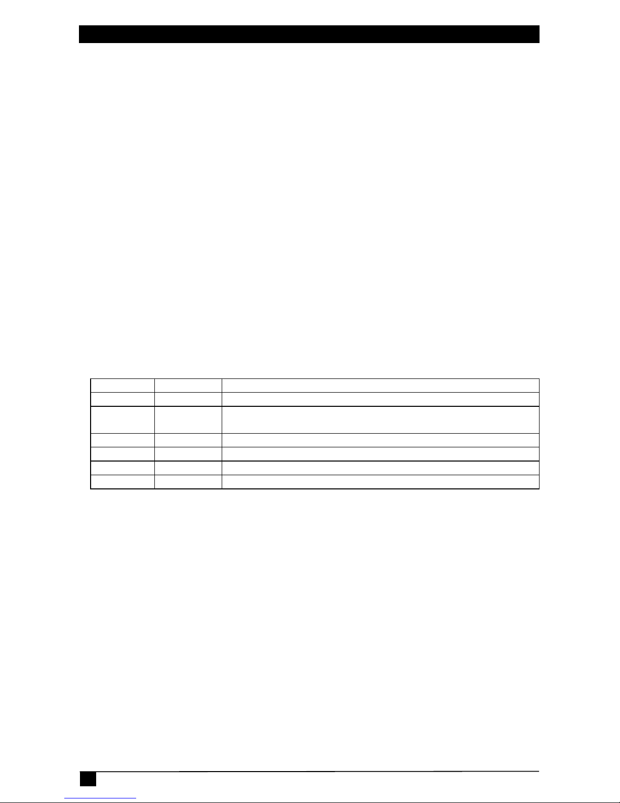
2. Allocate an address to each Satellite by positioning the address selection DIP-switches marked
Slct on the front panel according to the following table.
Remarks
- Unplug the device before changing its DIP switches.
- Do NOT use the same address for two different Satellites.
Satellite number DIP-switch 1 DIP-switch 2
1 Off Off
2 On Off
3 Off On
4 On On
Position Off = switch upwards
Position On = switch downwards
Micro-switch 1 is on the left side, micro-switch 2 on the right.
3. Plug the 2 power cables into 2 grounded sockets. The A and B LEDs light on to confirm that
power is on.
Page 8

POWER SWITCH PSE508MA & PSE508SA
6
3. Configuration of the Power Switch Master
Twin
To use the Power Switch Master Twin on your network, you must first configure its network
parameters. Ask your network administrator for the parameters to use.
There are two different methods to configure the Power Switch Master Twin:
Method 1:
Through a network using the Power Switch Finder Program (on the delivered CD).
It is the simplest and fastest configuration method if you use Windows as operating system. We
suggest that you use this program at least during the first configuration: it allows you to configure
your Power Switch Master Twin through your local network even if its network parameters (IP
Address, Subnet mask and Port) are not compatible with those of your PC or your local network.
If you decide to use this method you can directly go to § 3.1 "Configuration using the Power Switch
Finder program".
Default Network parameters:
IP address
192.168.100.100
Subnet mask
255.255.255.0
Gateway
no address
Port
80
Method 2:
Through a RS232 serial connection using a Terminal connection. If you use a PC, use the serial
cable supplied with the product and a Terminal program such as Widows HyperTerminal or the
MicroTerminal program on the CD (folder miscellaneous).
If you decide to use this method, you can directly go to § 3.2 "Configuration using a Terminal
connection".
Page 9

7
CHAPTER 3: Configuration
3.1 Configuration using the Power Switch Finder program
Remarks:
The Power Switch Master Twin and the PC used to configure it have to be connected on the same segment
of the network. The protocol of this program cannot be routed so it cannot be used to configure the Power
Switch through a WAN or the Internet.
This program does not work if the administrator has deactivated it in the configuration of the Power Switch
(for security reasons for example).
1. Start the PS-Finder.exe program on the CD-ROM.
The Power Switch Finder window appears.
2. In the tool bar click on the first left button or choose the File/Scan Menu.
The program browses the segment on which is connected your PC and displays the name, the
type, the IP and MAC Address of the connected Power Switch.
3. In the tool bar click on the second left button or choose the File/Configure Menu.
The properties dialog box appears and you can now configure the network parameters. To
configure all other parameters click on the Options button on the bottom of the dialog box.
Page 10

POWER SWITCH PSE508MA & PSE508SA
8
General Tab
This tab is used:
• to define all the network parameters of the Power Switch Master Twin (IP Address, Subnet
Mask, Default Gateway and Port Number).
• to permit or deny the configuration using the Power Switch Finder program for security reasons.
Labels Tab
This tab is used:
• to attribute a label to a group of Power Switch devices connected together (a group is made of 1
Power Switch Master Twin and up to 4 Satellites).
• to attribute a label to each Power Switch and its 8 power sockets (use the left vertical Tabs to
select the Power Switch you want to configure).
Accounts Tab
In combination with the left vertical tab Group, this tab is used:
• to attribute a name and a password to the administrator who has access to all the sockets within a
group of Power Switch.
In combination with one of the left vertical tabs «Device 1» to «Device 5», this tab is used:
• to define 8 user accounts using a name and a password for each one.
• to define the power sockets each user will be able to control.
• to activate or deactivate a Power Switch Satellite connected to the Master.
• to define the function modus of each Power Switch (Single mode or Twin mode):
- Single mode enables you to control individually each power socket,
- Twin mode enables you to control two power sockets with one command. This mode is
particularly intended to restart devices using redundant power supplies.
In that case, the 4 sockets powered by the power supply A (sockets 1 to 4) are automatically
associated to the 4 sockets powered by the power supply B (sockets 5 to 8) and the labels of the
first 4 sockets are used.
Security Tab
This tab is used to define addresses that are authorized or denied to access to the Power Switch over
the Network. For all details about these features, please refer to chapter 6 "Security parameters
configuration".
Options Tab
This tab is used to:
• define the restart delay valid for all power sockets of all Power Switch connected together;
• configure an Email address to which the user can manually send a message in case of problem.
Miscellaneous Tab
In combination with one of the left vertical tabs "Device 1" to "Device 5" to know how many times
a Power Switch has been powered ON and how many times its power sockets have been switched
from OFF to ON. These values cannot be reset by the user.
Page 11

9
CHAPTER 3: Configuration
3.2 Configuration using a Terminal connection
The RS232 serial port of the Power Switch Master Twin can be used to control its power socket and
to configure its Web server.
To configure the Web server using a PC and a Terminal connection:
1. Use the supplied RS232 serial cable to connect the Power Switch Master Twin to an available
serial port of your PC.
2. Run a terminal program such as Windows HyperTerminal or the MicroTerminal program on the
CD (folder miscellaneous).
3. Configure the appropriate serial port with the following settings:
9.600 bauds,
8 bits,
no parity,
1 stop bit,
no flow control.
If you use the MicroTerminal program on the CD (folder miscellaneous) you only have to
choose the used serial port, this program is already configured at 9600,n,8,1.
4. On your computer, press <ENTER> until the prompt «>» appears on your screen.
(the Power Switch Master Twin is now in Command mode and is waiting for commands to
switch the power sockets. The serial command mode is explained in § 6.2).
Page 12

POWER SWITCH PSE508MA & PSE508SA
10
5. Press the <TAB> key on your keyboard.
The Configuration menu appears on your screen and the Power Switch Master Twin is now in
the Configuration mode. Follow the menu to configure the Web server of your Power Switch
Master Twin.
All commands start with the slash «/»
ex.: type the command /NP to go to the Network Parameters settings menu.
To display the current menu again, press <ENTER>.
To go to the previous menu and to display it, press <ESC>.
Remark:
to leave the configuration mode, type the restart command /RS. This is particularly important if you want to
control the power socket later through the serial connection.
The configuration of the serial port is explained in § 5 (Serial port configuration).
>
Power Switch M8
Commands :
Configuration
/NP Network Parameters Settings
/PS Passwords Settings
/NS Group, Device and Socket Names Settings
/DP Device Parameters Settings
/RD Socket Restart Delay Settings
/IS IP Security Settings
/RS Restart the Device
Enter Selection
>
Page 13

11
CHAPTER 3: Configuration
MAIN CONFIGURATION MENU
The Main menu of the configuration mode displays all the commands that can be used.
• All commands start with the character slash «/»
(ex.: type the command /NP to go to the Network Parameters settings menu.
• To display the current menu again, press <ENTER>.
• To return to the previous menu and display it, press <ESC>.
Power Switch
Commands :
Configuration
/NP Network Parameters Settings
/PS Passwords Settings
/NS Group, Device and Socket Names Settings
/DP Device Parameters Settings
/RD Socket Restart Delay Settings
/IS IP Security Settings
/RS Restart the Device
Enter Selection
>
Page 14

POWER SWITCH PSE508MA & PSE508SA
12
NETWORK PARAMETERS SETTINGS MENU
Command /NP
This Menu is used to configure all network parameters (IP Address, Subnet Mask, Gateway and
Port) and to permit or prevent the configuration over a local area network using the special Power
Switch Finder program.
NETWORK PARAMETERS SETTINGS
MAC Address 00.01.9A.F1.00.0F
1. IP Address 192.168.100.100
2. Subnet Mask 255.255.255.0
3. Gateway 0.0.0.0
4. Port 80
5. Finder Activated
Enter Selection or <ESC> to exit
>
Command 1
NETWORK PARAMETERS SETTINGS
IP Address is: 192.168.100.100
Enter IP Address or <ESC> to exit
You must restart the device (Command /RS) to valid the new parameters
>
Command 2
NETWORK PARAMETERS SETTINGS
Subnet Mask is: 255.255.255.0
Enter subnet mask or <ESC> to exit
You must restart the device (Command /RS) to valid the new parameters
>
Command 3
NETWORK PARAMETERS SETTINGS
Gateway is: 0.0.0.0
Enter gateway address or <ESC> to exit
You must restart the device (Command /RS) to valid the new parameters
>
Command 4
NETWORK PARAMETERS SETTINGS
Port is: 80
Enter port or <ESC> to exit
You must restart the device (Command /RS) to valid the new parameters
>
Command 5
NETWORK PARAMETERS SETTINGS
Finder is: Activated
1. Activate
2. Deactivate
Enter Selection or <ESC> to exit
You must restart the device (Command /RS) to valid the new parameters
>
Page 15

13
CHAPTER 3: Configuration
PASSWORD SETTINGS MENU
Command /PS
This Menu is used to configure the names and the corresponding passwords for the administrator
and all the users.
PASSWORDS SETTINGS
1. Administrator
2. Users Device 1
3. Users Device 2
4. Users Device 3
5. Users Device 4
6. Users Device 5
Enter Selection or <ESC> to exit
>
Command 1
ADMINISTRATOR NAME & PASSWORD SETTINGS
1. Administrator Name admin
2. Administrator Password admin
Enter Selection or <ESC> to exit
>
Command 2
DEVICE 1 / USERS SETTINGS
1. User 1
2. User 2
3. User 3
4. User 4
5. User 5
6. User 6
7. User 7
8. User 8
Enter Selection or <ESC> to exit
>
Command 1
DEVICE 1 / USER 1 SETTINGS
1. User 1 Name user1-1
2. User 1 Password user1-1
3. User 1 authorized Sockets 1,5
Enter Selection or <ESC> to exit
>
Page 16

POWER SWITCH PSE508MA & PSE508SA
14
GROUP, DEVICE AND SOCKET NAMES SETTINGS
Command /NS
This Menu is used to attribute a label to a group of Power Switch, a label to each Power Switch
device and a label to each power socket.
GROUP, DEVICE AND SOCKET NAMES SETTINGS
1. Group Name Group Name
2. Device 1 & Socket Name Device 2 name
3. Device 2 & Socket Name Device 2 name
4. Device 3 & Socket Name Device 3 name
5. Device 4 & Socket Name Device 4 name
6. Device 5 & Socket Name Device 5 name
Enter Selection or <ESC> to exit
>
Command 1
GROUP NAME SETTING
Group Name is: Device Name
Enter Name (max. 32 characters) or <ESC> to exit
>
Command 2 to 6
DEVICE 1 / SOCKET NAMES SETTINGS
1. Device Name Device 1 name
2. Socket 1 Socket 1-1 name
3. Socket 2 Socket 1-2 name
4. Socket 3 Socket 1-3 name
5. Socket 4 Socket 1-4 name
6. Socket 5 Socket 1-5 name
7. Socket 6 Socket 1-6 name
8. Socket 7 Socket 1-7 name
9. Socket 8 Socket 1-8 name
Enter Selection or <ESC> to exit
Page 17

15
CHAPTER 3: Configuration
DEVICE PARAMETERS SETTINGS
Command /DP
This Menu is used to:
• configure an Email address to which the user can manually send a message in case of problem,
• define the function modus of each Power Switch device (Single mode or Twin mode),
Single mode enables you to control individually each power socket,
Twin mode enables you to control two power sockets with one command. This mode is
particularly intended to restart devices using redundant power supplies.
In this case, the 4 sockets powered by power supply A (sockets 1 to 4) are automatically
associated to the 4 sockets powered by power supply B (sockets 5 to 8) and the labels of the first
4 sockets are used.
• activate or deactivate a Power Switch Satellite connected to a Power Switch Master Twin.
DEVICE PARAMETERS SETTINGS
1. Mail to
2. Device #1 Activated Twin Mode
3. Device #2 Activated Twin Mode
4. Device #3 Not Activated Single Mode
5. Device #4 Not Activated Single Mode
6. Device #5 Not Activated Single Mode
Enter Selection or <ESC> to exit
>
Command 1
MAIL TO SETTING
Mail to is:
Enter Name (max. 32 characters) or <ESC> to exit
>
Command 2 to 6
DEVICE 1 PARAMETERS SETTINGS
Device #1 Activated Twin Mode
1. Single Mode / Twin Mode
2. Activate / Deactivate
Enter Selection or <ESC> to exit
>
Command 1
DEVICE 1 PARAMETERS SETTINGS
Mode is: Twin Mode
1. Twin Mode
2. Single Mode
Enter Selection or <ESC> to exit
>
Command 2
DEVICE 1 PARAMETERS SETTINGS
Device is: Activated
1. Activate
2. Deactivate
Enter Selection or <ESC> to exit
>
Page 18

POWER SWITCH PSE508MA & PSE508SA
16
SOCKET RESTART DELAY SETTINGS
Command /RD
This Menu is used to define the restart delay for all the power sockets.
SOCKET RESTART DELAY SETTINGS
1. Delay before Restart (sec) 5
Enter Selection or <ESC> to exit
>
Command 1
SOCKET RESTART DELAY SETTINGS
Delay before Restart (sec) is: 5
1. 5 sec
2. 10 sec
3. 15 sec
4. 30 sec
5. 60 sec
Enter Selection or <ESC> to exit
>
Command 1
SOCKET RESTART DELAY SETTINGS
1. Delay before Restart (sec) 5
Enter Selection or <ESC> to exit
>
Page 19

17
CHAPTER 3: Configuration
IP SECURITY SETTINGS
Command /IS
This Menu is used to define IP addresses or IP ranges that are authorized or not to access the Web
Server of the Power Switch Master Twin. See § 4 for all details.
IP SECURITY SETTINGS
1. Mask #1 0.0.0.0 Deny Not Activated
2. Mask #2 0.0.0.0 Deny Not Activated
3. Mask #3 0.0.0.0 Deny Not Activated
4. Mask #4 0.0.0.0 Deny Not Activated
5. Mask #5 0.0.0.0 Deny Not Activated
6. Mask #6 0.0.0.0 Deny Not Activated
7. Mask #7 0.0.0.0 Deny Not Activated
8. Mask #8 0.0.0.0 Deny Not Activated
Enter Selection or <ESC> to exit
>
Command 1
IP SECURITY SETTINGS
Mask #1 0.0.0.0 Deny Not Activated
1. Edit the Mask
2. Permit / Deny
3. Activate / Deactivate
Enter Selection or <ESC> to exit
>
Command 1
IP SECURITY SETTINGS
Mask #1 is: 0.0.0.0
Enter mask or <ESC> to exit
>
Command 2
IP SECURITY SETTINGS
Mask #1 Access is: Deny
1. Permit
2. Deny
Enter Selection or <ESC> to exit
>
Command 3
IP SECURITY SETTINGS
Mask #1 Supervision is: Not Activated
1. Activate
2. Deactivate
Enter Selection or <ESC> to exit
>
Page 20
POWER SWITCH PSE508MA & PSE508SA
18
RESTART THE DEVICE
Command /RS
This Menu is used to restart the Power Switch Master Twin.
This function is needed:
• to take into account changes of network parameters (command /NP),
• to leave the serial configuration mode and return to the command mode.
RESTART THE DEVICE
The system is reinitializing, please wait ...
>
Page 21

19
CHAPTER 4: Security parameters
4. Security parameters
Explanations about masks settings :
• Each mask can be an IP Address or a range of IP Addresses.
• Each mask allows you to permit or deny access to the Web server of the Power Switch Master
Twin for specific addresses or ranges of addresses.
• Each mask can be activated or deactivated (without function in this case).
• Each IP Address consists of a set of four eight-bit numbers. The number 255 is used as a
wildcard and replaces all others.
• Masks are listed in order of descending priority; so Mask 1 has the highest priority.
• Masks have a cumulative effect; high priority masks supersede the effect of lower priority
masks.
Example 1:
⇒ Deny the access to all IP addresses except 192.168.001.015
Mask IP Address Permit Deny Activated
#1 192.168.001.015
#2 255.255.255.255
Example 2:
⇒ Permit access only to IP addresses beginning with 192.
Mask IP Address Permit Deny Activated
#1 192.255.255.255
#2 255.255.255.255
Page 22

POWER SWITCH PSE508MA & PSE508SA
20
Example 3:
⇒ Permit access only to IP addresses beginning with 192
⇒ Deny access to IP address 192.168.001.010
Mask IP Address Permit Deny Activated
#1 192.168.001.010
#2 192.255.255.255
#3 255.255.255.255
Example 4:
⇒ Permit access to IP addresses beginning with 192
⇒ Deny access to address 192.168.001.010
⇒ Permit access to IP addresses beginning with 217.128.103
Mask IP Address Permit Deny Activated
#1 192.168.001.010
#2 192.255.255.255
#4 217.128.103.255
#3 255.255.255.255
Page 23

21
CHAPTER 5: Serial port configuration
5. Serial port configuration
Power Switch Master Twin
Connector: SUB-D9 female connector
Pin configuration Configuration parameters
Pin 2 = TxD (transmit data to the PC) Speed: 9600 bauds
Pin 3 = RxD (receive commands) Parity: No
Pin 5 = GnD Format: 8 bits
Stop bit: 1
Flow control: no
Remarks:
- The serial cable provided with Power Switch Master Twin is a standard straight extension cable with DB9
connectors. This cable is intended to connect the serial port of the Power Switch Master Twin to a serial
port of a PC.
- You may use any other straight serial cable, but for EMC reasons, we advise you not to use cables above
2.9 meters long.
Power Switch Satellite
Connector: RJ9 female
Pin configuration Configuration parameters
1 (yellow) = Ground Speed: 9600 bauds
2 (white) = RxD (receive commands) Parity: No
3 (blue) = TxD (transmit data) Format: 8 bits
4 (orange) = Ground Stop bit: 1
Flow control: no
A short connection cable is supplied with each Power Switch Satellite Twin.
This cable is used to connect its RJ9 input connector to the RJ9 output connector of a Power Switch
Master Twin or another Power Switch Satellite Twin.
If you want to connect the Power Switch Satellite directly to the serial port of a PC, make a serial
cable as indicated by the drawing below or contact your dealer to order one.
Page 24

POWER SWITCH PSE508MA & PSE508SA
22
6. Control the power outlets
6.1 Control the power outlets through a Web browser
1. Start your Web browser.
Type the IP address of your Power Switch Master Twin.
The browser displays the authentication dialog box.
2. Enter a user name and its corresponding password.
With the administrator name (default value = admin) and the administrator password (default
value = admin), you will be able to control all the power sockets and also to configure all the
parameters of the Power Switch Master Twin.
With a user name and its password you will only be able to control the socket status.
Home page in «Single mode»
Home page in «Twin mode»
The Power button allows you to switch the socket ON and OFF.
The Restart button allows you to switch OFF the socket. It will be automatically switched on
after the delay set by the administrator during the configuration (default value is 5 sec).
Page 25

23
CHAPTER 6: Control the power outlets
Default Configuration of the Power Switch Master Twin
IP address 192.168.100.100 Administrator Name : admin
Subnet mask 255.255.255.0 Administrator Password : admin
Gateway no address
Port 80
Page 26

POWER SWITCH PSE508MA & PSE508SA
24
6.2 Control the power outlets through a serial connection
The power sockets of the Power Switch Master Twin and the Power Switch Satellite Twin can be
controlled using a simple ASCII protocol over an RS232 serial connection.
C
ONTROL THE POWER SOCKETS OF THE POWER SWITCH MASTER TWIN AND ITS SATELLITES
1. Use the supplied RS232 serial cable to connect the Power Switch Master Twin to an available
serial port of your PC.
2. Run a terminal program such as Windows HyperTerminal or the MicroTerminal program on the
CD (folder miscellaneous).
3. Configure the appropriate serial port with the following settings:
9.600 bauds, 8 bits, no parity, 1 stop bit and no flow control.
If you use the MicroTerminal program on the CD (folder miscellaneous) you only have to
choose the used serial port, this program is already configured at 9600,n,8,1.
4. On your computer, press <ENTER> until the prompt «>» appears on your screen. This prompt
indicates that the Power Switch Master Twin is in Command mode (it is the default mode after
Power up).
Remark:
The power socket of the Power Switch can only be controlled if the Power Switch is in Command mode and
NOT in Configuration mode. If you are in Configuration mode, type the command /RS to leave this mode.
Page 27

25
CHAPTER 6: Control the power outlets
The syntax of the command line is: Pxy=z
Parameter Value Function
x 1 to 5 represents the number of the Power Switch:
1 means Power Switch Master Twin
2 to 5 means the corresponding connected Satellite
y 0
1 to 8
means that all the sockets have to be controlled together
indicates the number of the socket you want to control
z 0 Command to switch the socket(s) Off
1 Command to switch the socket(s) On
r Command to restart the socket(s)
t Command to toggle the state of the socket
Example to control the Master:
P10=1 <ENTER> switch all the 8 sockets ON
P10=0 <ENTER> switch all the 8 sockets OFF
P14=r <ENTER> restart socket 4
P18=t <ENTER> toggle socket 8
Example to control the first Satellite connected to the Master
DIP-Switch of the Satellite: 1 = off and 2 = off
P20=1 <ENTER> switch all the 8 sockets ON
P25=0 <ENTER> switch socket 5 OFF
Remarks:
- The Power Switch accepts lower case and upper case commands.
- The Power Switch sends an echo for each received character.
- If the Twin mode is activated, sending a command to a specific socket number will also control its
corresponding twin socket.
Page 28
POWER SWITCH PSE508MA & PSE508SA
26
C
ONTROL THE POWER SOCKETS OF A POWER SWITCH SATELLITE TWIN OR SEVERAL SATELLITES
CONNECTED TOGETHER
In this case, you have to make a special serial cable as indicated by the drawing in §7 or contact
your dealer to order one.
1. Use this special cable to connect the Power Switch Satellite Twin to an available serial port of
your PC.
2. Run a terminal program such as Windows HyperTerminal or the MicroTerminal program on the
CD (folder miscellaneous).
3. Configure the appropriate serial port with the following settings:
9.600 bauds, 8 bits, no parity, 1 stop bit and no flow control.
If you use the MicroTerminal program on the CD (folder miscellaneous) you only have to
choose the used serial port, this program is already configured at 9600,n,8,1.
4. From your computer, enter the command as explained below.
The syntax of the command line is: Pxy=z
Parameter Value Function
x 1 to 4 1 to 4 means the corresponding connected Satellite
y 0
1 to 8
means that all the sockets have to be controlled together
indicates the number of the socket you want to control
z 0 Command to switch the socket(s) OFF
1 Command to switch the socket(s) ON
r Command to restart the socket(s)
t Command to toggle the state of the socket
Example to control the first Satellite
DIP-Switch: 1 = off and 2 = off
P10=1 <ENTER> switch all 8 sockets ON
P10=0 <ENTER> switch all 8 sockets OFF
P14=r <ENTER> restart socket 4
P18=t <ENTER> toggle socket 8
Example to control the second Satellite
DIP-Switch: 1 = on and 2 = off
P20=1 <ENTER> switch all 8 sockets ON
P25=0 <ENTER> switch socket 5 OFF
Remarks:
- The Power Switch accepts lower case and upper case commands.
- The Power Switch sends an echo for each received character.
Page 29

CHAPTER 7: Technical data
27
7. Technical data
7.1 Power Switch Master Twin
Network standards
IEEE 802.3, 10BASE-T
Network protocols
TCP/IP, HTTP
Network connection
RJ-45 connector for UTP CAT5
Maximal network cable length
100 meters (cable not included)
Serial connection
RS232, SUB-D 9 female
Nominal input voltage
230 V/50Hz
Input power socket
IEC-320
Output voltage
230 V/50Hz
Output power socket
IEC-320
Maximum total current
2 x 10 A
LEDs
1 for Power Supply A
1 for Power Supply B
8 for the power sockets status
1 for Web server Power and Network traffic
4 for the connected Satellites
Operating temperature
0°C to +40°C
Operating humidity
10% to 80%
Dimensions (LxDxH)
437 x 107 x 42 mm
Weight
2 Kg
Page 30

POWER SWITCH PSE508MA & PSE508SA
28
7.2 Power Switch Satellite Twin
Serial connection
RS232, SUB-D 9 female
Nominal input voltage
230 V/50Hz
Input power socket
IEC-320
Output voltage
230 V/50Hz
Output power socket
IEC-320
Maximum total current
2 x 10 A
LEDs
1 for Power and Network Traffic
1 for socket status
Operating temperature
0°C to +40°C
Operating humidity
10% to 80%
Dimensions
437 x 107 x 42 mm
Weight
2 Kg
Page 31

© Copyright 2006. Black Box Corporation. All rights reserved.
BLACK BOX Network Services
 Loading...