

Page 1
SEPTEMBER 2006
PS590A
PS590AE
PS591A
PS591AE
Rackmount Remote Power Manager Dual 20-Amp
Rackmount Remote Power Manager Dual 16-Amp
Rackmount Remote Power Manager 16 Dual 20-Amp
Rackmount Remote Power Manager 16 Dual 16-Amp
CUSTOMER
SUPPORT
INFORMATION
Order toll-free in the U.S.: Call 877-877-BBOX (outside U.S. call 724-746-5500)
FREE technical support 24 hours a day, 7 days a week: Call
Mailing address: Black Box Corporation, 1000 Park Drive, Lawrence, PA 15055-1018
Web site: www.blackbox.com
• E-mail: info@blackbox.com
724-746-5500 or fax 724-746-0746
Page 2

Page 3

FCC AND IC RFI STATEMENTS/CE NOTICE
FEDERAL COMMUNICATIONS COMMISSION
AND
INDUSTRY CANADA
RADIO FREQUENCY INTERFERENCE STATEMENTS
This equipment generates, uses, and can radiate radio-frequency energy, and if not
installed and used properly, that is, in strict accordance with the manufacturer’s
instructions, may cause interference to radio communication. It has been tested
and found to comply with the limits for a Class A computing device in accordance
with the specifications in Subpart B of Part 15 of FCC rules, which are designed
to provide reasonable protection against such interference when the equipment is
operated in a commercial environment. Operation of this equipment in a residential
area is likely to cause interference, in which case the user at his own expense will be
required to take whatever measures may be necessary to correct the interference.
Changes or modifications not expressly approved by the party responsible for
compliance could void the user’s authority to operate the equipment.
This digital apparatus does not exceed the Class A limits for radio noise emission
from digital apparatus set out in the Radio Interference Regulation of Industry
Canada.
Le présent appareil numérique n’émet pas de bruits radioélectriques dépassant
les limites applicables aux appareils numériques de la classe A prescrites dans le
Règlement sur le brouillage radioélectrique publié par Industrie Canada.
EUROPEAN UNION DECLARATION OF CONFORMITY
This equipment complies with the requirements of the European EMC Directive
89/336/EEC.
1
Page 4

RACKMOUNT REMOTE POWER MANAGERS
NORMAS OFICIALES MEXICANAS (NOM)
ELECTRICAL SAFETY STATEMENT
INSTRUCCIONES DE SEGURIDAD
1. Todas las instrucciones de seguridad y operación deberán ser leídas antes de
que el aparato eléctrico sea operado.
2. Las instrucciones de seguridad y operación deberán ser guardadas para
referencia futura.
3. Todas las advertencias en el aparato eléctrico y en sus instrucciones de
operación deben ser respetadas.
4. Todas las instrucciones de operación y uso deben ser seguidas.
5. El aparato eléctrico no deberá ser usado cerca del agua—por ejemplo, cerca
de la tina de baño, lavabo, sótano mojado o cerca de una alberca, etc..
6. El aparato eléctrico debe ser usado únicamente con carritos o pedestales que
sean recomendados por el fabricante.
7. El aparato eléctrico debe ser montado a la pared o al techo sólo como sea
recomendado por el fabricante.
8. Servicio—El usuario no debe intentar dar servicio al equipo eléctrico más
allá a lo descrito en las instrucciones de operación. Todo otro servicio deberá
ser referido a personal de servicio calificado.
9. El aparato eléctrico debe ser situado de tal manera que su posición no
interfiera su uso. La colocación del aparato eléctrico sobre una cama, sofá,
alfombra o superficie similar puede bloquea la ventilación, no se debe colocar
en libreros o gabinetes que impidan el flujo de aire por los orificios de
ventilación.
10. El equipo eléctrico deber ser situado fuera del alcance de fuentes de calor
como radiadores, registros de calor, estufas u otros aparatos (incluyendo
amplificadores) que producen calor.
11. El aparato eléctrico deberá ser connectado a una fuente de poder sólo del tipo
descrito en el instructivo de operación, o como se indique en el aparato.
2
Page 5

NOM STATEMENT
12. Precaución debe ser tomada de tal manera que la tierra fisica y la polarización
del equipo no sea eliminada.
13. Los cables de la fuente de poder deben ser guiados de tal manera que no sean
pisados ni pellizcados por objetos colocados sobre o contra ellos, poniendo
particular atención a los contactos y receptáculos donde salen del aparato.
14. El equipo eléctrico debe ser limpiado únicamente de acuerdo a las
recomendaciones del fabricante.
15. En caso de existir, una antena externa deberá ser localizada lejos de las lineas
de energia.
16. El cable de corriente deberá ser desconectado del cuando el equipo no sea
usado por un largo periodo de tiempo.
17. Cuidado debe ser tomado de tal manera que objectos liquidos no sean
derramados sobre la cubierta u orificios de ventilación.
18. Servicio por personal calificado deberá ser provisto cuando:
A: El cable de poder o el contacto ha sido dañado; u
B: Objectos han caído o líquido ha sido derramado dentro del aparato; o
C: El aparato ha sido expuesto a la lluvia; o
D: El aparato parece no operar normalmente o muestra un cambio en su
desempeño; o
E: El aparato ha sido tirado o su cubierta ha sido dañada.
3
Page 6

RACKMOUNT REMOTE POWER MANAGERS
TRADEMARKS USED IN THIS MANUAL
BLACK BOX and the Double Diamond logo are registered trademarks of BB
Technologies, Inc.
ProComm is a registered trademark of DATASTORM TECHNOLOGIES, INC.™
Crosstalk is a registered trademark of Digital Communications Associates, Inc.
VT100 is a trademark of Digital Equipment Corporation.
AT is a registered trademark of International Business Machines Corporation.
Netscape Navigator is a registered trademark of Netscape Communications
Corporation.
JavaScript is a registered trademark of Sun Microsystems, Inc.
Telnet is a trademark of Telnet Communications, Inc.
UNIX is a registered trademark of UNIX System Laboratories, Inc.
Any other trademarks mentioned in this manual are acknowledged to be the property
of the trademark owners.
4
Page 7

WARNINGS AND CAUTIONS
WARNINGS AND CAUTIONS
Secure Racking
If secure racked units are installed in a closed or multi-unit rack assembly, they
may require further evaluation by certification agencies. Consider the following
items:
1. The ambient temperature within the rack may be greater than the room
ambient temperature. Installation should be such that the amount of
airflow required for safe operation is not compromised. The maximum
temperature for the equipment in this environment is 122°F (50°C).
2. Install the unit so that it doesn’t become unstable from uneven loading.
Input Supply
Check nameplate ratings to ensure that there is no overloading of supply
circuits that could have an effect on overcurrent protection and supply wiring.
Grounding
Maintain reliable grounding of this equipment. Give particular attention
to supply connections when connecting to power strips, rather than direct
connections to the branch circuit.
Shock Hazard
Do not attempt to repair or service this device yourself. Internal components
must be serviced by authorized personnel only.
Disconnect Power
If any of the following events occurs, immediately disconnect the unit from the
outlet and contact Black Box at 724-746-5500.
1. The power cord is frayed or damaged.
2. Liquid has been spilled into the device or the device has been exposed
to rain or water.
Disconnect Both Power Supply Cables
This unit includes two separate power circuits with a power supply cable for
each circuit. Before attempting to service or remove this unit, make certain that
both power cables are disconnected.
5
Page 8

RACKMOUNT REMOTE POWER MANAGERS
Contents
1. Specifications . . . . . . . . . . . . . . . . . . . . . . . . . . . . . . . . . . . . . . . . . . . . . . . . . . . 8
2. Quick Start Guide . . . . . . . . . . . . . . . . . . . . . . . . . . . . . . . . . . . . . . . . . . . . . . . 10
2.1. Hardware Installation . . . . . . . . . . . . . . . . . . . . . . . . . . . . . . . . . . . . . . . 10
2.1.1. Apply Power to the Rackmount Remote Power Manager . . . . . 10
2.2.2. Connect your PC to the Rackmount Remote Power Manager . . 10
2.2. Communicating with the Rackmount Remote Power Manager . . . . . . . 11
3. Overview . . . . . . . . . . . . . . . . . . . . . . . . . . . . . . . . . . . . . . . . . . . . . . . . . . . . . . 15
3.1. Back Panel Components - Models PS590A and PS590AE . . . . . . . . . . 17
3.2. Back Panel Components - Models PS591A and PS591AE . . . . . . . . . . 19
4. Installation . . . . . . . . . . . . . . . . . . . . . . . . . . . . . . . . . . . . . . . . . . . . . . . . . . . . . 21
4.1. Power Cable (and Cable Keeper) Connection . . . . . . . . . . . . . . . . . . . . 21
4.1.1. Models PS590A and PS590AE . . . . . . . . . . . . . . . . . . . . . . . . . . 21
4.1.2. Models PS591A and PS591AE . . . . . . . . . . . . . . . . . . . . . . . . . . 22
4.2. Connection to Switched Outlets . . . . . . . . . . . . . . . . . . . . . . . . . . . . . . . 22
4.3. Serial COM/RS-232 Port Connection . . . . . . . . . . . . . . . . . . . . . . . . . . . 23
4.3.1. Connecting a Local PC to the COM/RS-232 Port . . . . . . . . . . . 24
4.3.2. Connecting an External Modem to the COM/RS-232 Port . . . . 24
4.4. Connecting the Network Cable . . . . . . . . . . . . . . . . . . . . . . . . . . . . . . . . 24
5. Configuration . . . . . . . . . . . . . . . . . . . . . . . . . . . . . . . . . . . . . . . . . . . . . . . . . . 25
5.1. System Mode and User Mode . . . . . . . . . . . . . . . . . . . . . . . . . . . . . . . . . 25
5.2. Communicating with the Rackmount Remote Power Manager . . . . . . . 26
5.2.1. Accessing the Web Browser Interface . . . . . . . . . . . . . . . . . . . . 26
5.2.2. Accessing the Text Interface . . . . . . . . . . . . . . . . . . . . . . . . . . . . 28
5.3. Configuration Menus . . . . . . . . . . . . . . . . . . . . . . . . . . . . . . . . . . . . . . . 30
5.3.1. General Parameters Menus . . . . . . . . . . . . . . . . . . . . . . . . . . . . . 31
5.3.2. Serial (Console) Port Parameters Menus . . . . . . . . . . . . . . . . . . 34
5.3.3. Plug Parameters Menus . . . . . . . . . . . . . . . . . . . . . . . . . . . . . . . . 36
5.3.4. Network Parameters Menus . . . . . . . . . . . . . . . . . . . . . . . . . . . . 40
5.3.5. Telnet Parameters Menus . . . . . . . . . . . . . . . . . . . . . . . . . . . . . . 44
5.3.6. Web Server Parameters Menus . . . . . . . . . . . . . . . . . . . . . . . . . . 45
5.4. Save Configuration Parameters . . . . . . . . . . . . . . . . . . . . . . . . . . . . . . . . 46
6
Page 9

CONTENTS
Contents (Continued)
6. Operation . . . . . . . . . . . . . . . . . . . . . . . . . . . . . . . . . . . . . . . . . . . . . . . . . . . . . . 47
6.1. Operation via the Web Browser Interface . . . . . . . . . . . . . . . . . . . . . . . . 47
6.1.1. The Plug Status Screen (Switch Panel) -
Web Browser Interface . . . . . . . . . . . . . . . . . . . . . . . . . . . . . . . . 47
6.1.2. Controlling Power - Web Browser Interface . . . . . . . . . . . . . . . . 48
6.2. Operation via the Text Interface . . . . . . . . . . . . . . . . . . . . . . . . . . . . . . . 50
6.2.1. The Plug Status Screen - Text Interface . . . . . . . . . . . . . . . . . . . 50
6.2.2. Controlling Power - Text Interface . . . . . . . . . . . . . . . . . . . . . . . 51
6.2.3. Applying Commands to Several Plugs . . . . . . . . . . . . . . . . . . . . 53
6.3. Logging Out of Command Mode . . . . . . . . . . . . . . . . . . . . . . . . . . . . . . 54
6.4. The Automated Mode . . . . . . . . . . . . . . . . . . . . . . . . . . . . . . . . . . . . . . . 54
6.5. Manual Operation . . . . . . . . . . . . . . . . . . . . . . . . . . . . . . . . . . . . . . . . . . 55
7. Saving and Restoring Configuration Parameters . . . . . . . . . . . . . . . . . . . . . . . 56
7.1. Sending Parameters to a File . . . . . . . . . . . . . . . . . . . . . . . . . . . . . . . . . . 56
7.2. Restoring Saved Parameters . . . . . . . . . . . . . . . . . . . . . . . . . . . . . . . . . . 57
7.3. Uploading Saved Parameters to Other Power Managers . . . . . . . . . . . . 57
8. Upgrading Firmware . . . . . . . . . . . . . . . . . . . . . . . . . . . . . . . . . . . . . . . . . . . . . 58
Appendix A: Troubleshooting . . . . . . . . . . . . . . . . . . . . . . . . . . . . . . . . . . . . . . . . . 60
A.1. Calling Black Box . . . . . . . . . . . . . . . . . . . . . . . . . . . . . . . . . . . . . . . . . . 60
A.2. Shipping and Packaging . . . . . . . . . . . . . . . . . . . . . . . . . . . . . . . . . . . . . 60
7
Page 10

RACKMOUNT REMOTE POWER MANAGERS
1. Specifications
Power Input / Output:
Model PS590A:
• AC Input: Two Separate Circuits; 20 Amps Max. per Circuit.
▪ Voltage: 100 - 120 VAC, 50/60 Hz.
▪ Connectors: Two (2) IEC-320-C20 Inlets.
• AC Outputs: 100 - 120 VAC, 50/60 Hz.
▪ Connectors: Eight (8) NEMA 5-15R Outlets.
▪ Load: 15 Amps per Outlet. 20 Amps per Circuit; Providing a Total of
40 Amps Combined.
Model PS590AE:
• AC Input: Two Separate Circuits; 16 Amps Max. per Circuit.
▪ Voltage: 100 - 240 VAC, 50/60 Hz.
▪ Connectors: Two (2) IEC-320-C20 Inlets.
• AC Outputs: 100 - 240 VAC, 50/60 Hz.
▪ Connectors: Eight (8) IEC-320-C13 Outlets.
▪ Load: 10 Amps per Outlet. 16 Amps per Circuit; Providing a Total of
32 Amps Combined.
Model PS591A:
• AC Input: Two Separate Circuits; 20 Amps Max. per Circuit.
▪ Voltage: 100 - 120 VAC, 50/60 Hz.
▪ Connectors: Two (2) IEC320-C20 Inlets.
• AC Outputs: 100 - 120 VAC, 50/60 Hz.
▪ Connectors: Sixteen (16) NEMA 5-15R Outlets.
▪ Load: 15 Amps per Outlet. 20 Amps per Circuit; Providing a
Total of 40 Amps Combined.
Model PS591AE:
• AC Input: Two Separate Circuits; 20 Amps Max. per Circuit.
▪ Voltage: 100 - 240 VAC, 50/60 Hz.
▪ Connectors: Two (2) IEC320-C20 Inlets.
• AC Outputs: 100 - 240 VAC, 50/60 Hz.
▪ Connectors: Sixteen (16) IEC-320-C13 Outlets.
▪ Load: 10 Amps per Outlet. 16 Amps per Circuit; Providing a
Total of 32 Amps Combined.
8
Page 11

Control Ports:
• Ethernet Port: 10Base-T
• COM Port: DB9M, RS232C, DTE
• RS232 Coding: Serial ASCII, 7/8 Bits
Physical / Environmental:
Size:
• Models PS590A & PS590AE:
▪ Width: 17.5” (44.5 cm) Standard Rack
▪ Depth: 7.0” (17.8 cm)
▪ Height: 1.75” (4.5 cm) 1 Rack U
• Models PS591A & PS591AE:
▪ Width: 17.5” (44.5 cm) Standard Rack
▪ Depth: 7.0” (17.8 cm)
▪ Height: 3.5” (8.9 cm) 2 Rack U
Shipping Weight:
• Models PS590A & PS590AE: 10 lbs (4.5 Kg)
• Models PS591A & PS591AE: 12 lbs (5.5 Kg)
Operating Temperature: 32°F to 122°F (0°C to 50°C)
Humidity: 10 - 90% RH
CHAPTER 1: Specifications
9
Page 12

RACKMOUNT REMOTE POWER MANAGERS
2. Quick Start Guide
To take full advantage of the complete range of features that the Rackmount Remote
Power Manager offers, we recommend that you read Chapters 4 and 5 after
performing this quick start procedure.
2.1. Hardware Installation
2.1.1. Apply Power to the Rackmount Remote Power Manager
Refer to power rating nameplate on the Rackmount Remote Power Manager’s
back panel, and then connect the unit to an appropriate power source. Note that
the Rackmount Remote Power Manager features two separate AC inputs and two
separate power busses; connect power cables to the unit's Circuit "A" and Circuit
"B" Power Inlets, install the cable keepers as described in Section 4.1, then connect
the cables to an appropriate power supply. Refer to the power rating nameplate for
information regarding power requirements and maximum loads.
Set the Main Power Switch in the ON position; the ON LED should light, and the
RDY LED should begin to flash.
CAUTION
Review the safety precautions listed on page 5 and in Section 4.1.
2.2.2. Connect your PC to the Rackmount Remote Power Manager
The Rackmount Remote Power Manager can either be controlled by a local PC, that
communicates with the unit via cable, controlled via external modem, or controlled
via TCP/IP network. In order to switch plugs or select parameters, commands are
issued to the Rackmount Remote Power Manager via either the Network Port or
Console Port. Note that it is not necessary to connect to both the Network and
Console Ports, and that the Console Port can be connected to either a local PC or an
External Modem.
• Network Port: Connect your 10Base-T or 100Base-T network interface to
the Rackmount Remote Power Manager’s Network port.
• Console Port: Use the supplied null modem cable to connect your PC COM
port to the Rackmount Remote Power Manager’s COM (RS232) Port.
• External Modem: Use a standard AT to Modem cable to connect your
external modem to the Rackmount Remote Power Manager’s COM
(RS232) Port.
10
Page 13

CHAPTER 2: Quick Start Guide
Note that when the Rackmount Remote Power Manager is shipped from the factory,
RS232 Port Parameters are set as follows: 9600 bps, 8 Data Bits, One Stop Bit, No
Parity. Although the Rackmount Remote Power Manager allows these parameters to
be easily redefined, for the purpose of this Quick Start procedure, it is recommended
that you configure your communications program to accept these default parameters.
2.2. Communicating with the Rackmount Remote Power Manager
The Rackmount Remote Power Manager offers two separate user interfaces: the
Web Browser Interface and the Text Interface. The Web Browser interface allows
you to contact the Rackmount Remote Power Manager via a TCP/IP network, using
a standard, JavaScript enabled web browser (such as Internet Explorer.) The Text
Interface consists of a series of ASCII text menus, which may be accessed via TCP/
IP network, Local PC or modem.
Note
The Rackmount Remote Power Manager features a default
IP Address (192.168.168.168) and a default Subnet Mask
(255.255.255.0). This allows initial network access to command
mode without first setting up the unit’s network parameters
(providing that you are contacting the Rackmount Remote Power
Manager from a node on the same subnet.) When attempting to
access the Rackmount Remote Power Manager from a node that
is not on the same subnet, please refer to Section 5.3.4 for further
configuration instructions.
1. Access the Command Mode: This procedure differs slightly, depending on
whether you’re contacting the Rackmount Remote Power Manager via the
Web Browser Interface or Text Interface.
a) Web Browser Interface: Start your JavaScript enabled Web Browser.
Enter the Rackmount Remote Power Manager’s default IP address
(192.168.168.168) in your browser address bar and then press [Enter].
A password prompt will be displayed. Since at this point, the user name
and password have not yet been defined, you can simply click OK
without keying in a user name or password. The Plug Status Screen will
be displayed as shown in Figure 2-1.
11
Page 14
RACKMOUNT REMOTE POWER MANAGERS
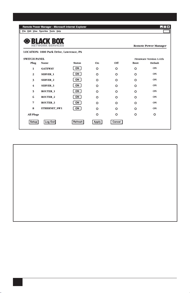
Figure 2-1: Plug Status Screen - Web Browser Interface
(8-Plug Model Shown)
Rackmount Remote Power Manager v1.41 Site ID: Black Box — Lawrence, PA
Plug | Name | Password | Status | Boot/Seq.Delay | Default |
----------------------------------------------------------------------------+
1 | GATEWAY | (undefined) | ON | 0.5 Secs | ON |
2 | SERVER_1 | (undefined) | ON | 1 min | ON |
3 | SERVER_2 | (undefined) | ON | 0.5 Secs | ON |
4 | SERVER_3 | (undefined) | ON | 0.5 Secs | OFF |
5 | ROUTER_1 | (defined) | ON | 0.5 Secs | ON |
6 | ROUTER_2 | (defined) | ON | 0.5 Secs | ON |
7 | ROUTER_3 | (defined) | ON | 0.5 Secs | OFF |
8 | ETHERNET_SW1 | (undefined) | ON | 0.5 Secs | ON |
----------------------------------------------------------------------------+
“/H” for help.
RPM>
Figure 2-3: Plug Status Screen - Text Interface
(8-Plug Model Shown)
12
Page 15

CHAPTER 2: Quick Start Guide
b) Text Interface:
i. Via Telnet: Telnet to the Rackmount Remote Power Manager’s
default IP address (192.168.168.168). The Plug Status Screen
(Figure 2-2) should be displayed.
ii. Via Local PC: Start your communications program (e.g.,
Hyperterminal) and then press [Enter]. The Plug Status Screen
should be displayed as shown in Figure 2-2. The default
communications parameters for the Console Port are 9600 bps, No
Parity, 8 data bits, One stop bit.
iii. Via Modem: Use your communications program to dial the
number for the phone line which is connected to your external
modem. Note that in order to communicate with the unit via
modem, you must first access the command mode via Network or
Local PC, and use the Serial Parameters Menu to set the Port Mode
to "Modem."
2. Test Switching Functions: You may wish to perform the following tests
in order to make certain that the Rackmount Remote Power Manager is
responding to commands.
a) Reboot Outlet: If you are communicating with the unit via the Web
Browser Interface, select the button in the "Boot" column for Plug 1, and
then click on Apply. If you are operating the unit via the Text interface,
type /BOOT 1 and press [Enter]. The status indicator for Plug 1
should go off, pause for a moment, and then go back on, indicating that
the boot cycle has been successfully completed.
b) Switch Outlet Off: From the Web Browser Interface, select the button
in the "Off" column for Plug 1, and then click Apply. From the Text
Interface, type /OFF 1 and press [Enter]. The status indicator for
Plug 1 should go Off, indicating that the command has been successfully
completed. Leave Plug 1 in the "Off" state, and then proceed to the next
step.
c) Switch Outlet On: From the Web Browser Interface, select the button
in the "On" column for Plug 1, and then click Apply. From the Text
Interface, type /ON 1 and press [Enter]. The status indicator for
Plug 1 should then go back On, indicating that the command has been
successfully completed.
13
Page 16

RACKMOUNT REMOTE POWER MANAGERS
3. Log Out: When you have finished communicating with the unit it is
important to always log off by issuing the appropriate Rackmount Remote
Power Manager command, rather than simply closing your Telnet or
communications program. When you log off using the proper command,
this ensures that the unit has completely exited from command mode, and
is not waiting for the inactivity timeout to elapse before allowing additional
connections.
a) Web Browser Interface: Click on the "Log Out" button.
b) Text Interface: Type /X and press [Enter].
This completes the Quick Start Guide for the Rackmount Remote Power Manager.
Prior to placing the unit into operation, it is recommended to refer to the remainder
of this User’s Guide for important information regarding advanced configuration
capabilities and more detailed operation instructions.
14
Page 17

CHAPTER 3: Overview
3. Overview
Electronic equipment sometimes “locks up,” requiring a service call just to flip
the switch to perform a simple reboot. The Rackmount Remote Power Manager
gives you the ability to perform this function from anywhere. You can access the
Rackmount Remote Power Manager via Web-browser or Text Interface.
To access the Rackmount Remote Power Manager via the Web Browser Interface,
assign an Internet IP address to the Rackmount Remote Power Manager. Then type
in the IP address in your Internet browser. You will be asked to enter a user name
and password. Finally, a Web Browser Interface screen will appear. Follow the
instructions on the screen to remotely power on, off, or reboot your equipment. (See
Section 5.2.1 for more details.)
In addition to access via the Web browser, the Rackmount Remote Power Manager
can also communicate over any TCP/IP network using standard Telnet, or out-ofband using an external modem and basic VT100™ type terminal emulation. To
access the Rackmount Remote Power Manager via the Text Interface by network,
PC, or modem, follow the instructions in Section 5.2.2.
The Rackmount Remote Power Manager provides two levels of passwords: the
system administrator level, which allows access to all configuration and switching
functions, and the user level, which allows access only to assigned plugs and cannot
be used to change the Rackmount Remote Power Manager’s configuration.
In addition to password security, the Rackmount Remote Power Manager also
includes an address-specific IP security mask. This prevents unauthorized network
access to the Rackmount Remote Power Manager’s command mode.
Easy-to-use commands are used to assign a location name, set system parameters,
and view plug status. Switch outlets on or off, or boot using plug numbers or names.
15
Page 18

RACKMOUNT REMOTE POWER MANAGERS
This User’s Guide covers four different Rackmount Remote Power Manager models:
• PS590A Rackmount Remote Power Manager - Dual 20-Amp:
Two (2) 100 to 120 VAC power circuits with individual power inlets and
breakers, eight (8) NEMA 5-15R outlets, 20-amps maximum per circuit
(Total 40-amps maximum.)
• PS590AE Rackmount Remote Power Manager - Dual 16-Amp:
Two (2) 100 to 240 VAC power circuits with individual power inlets and
breakers, eight (8) IEC-320-C13 outlets, 16-amps maximum per circuit (Total
32-amps maximum.)
• PS591A Rackmount Remote Power Manager 16 Dual 20-Amp:
Two (2) 100 to 120 VAC power circuits with individual power inlets and
breakers, sixteen (16) NEMA 5-15R outlets, 20-amps maximum per circuit
(Total 40-amps maximum.)
• PS591AE Rackmount Remote Power Manager 16 - Dual 16-Amp:
Two (2) 100 to 240 VAC power circuits with individual power inlets and
breakers, sixteen (16) IEC-320-C13 outlets, 16-amps maximum per circuit
(Total 32-amps maximum.)
Throughout this User’s Guide, all four units are referred to as the Rackmount
Remote Power Manager. Aside from the input voltages and maximum loads
summarized above, all other features function identically for all five models, except
where noted.
16
Page 19
CHAPTER 3: Overview
BUS
A
B
A-1 A-2 A-3 A-4 B-5 B-6 B-7 B-8
MAIN POWER
COM
10BaseT
ACT
RDY
ON
DEF
1
2
3
4
5
6
7
8
9
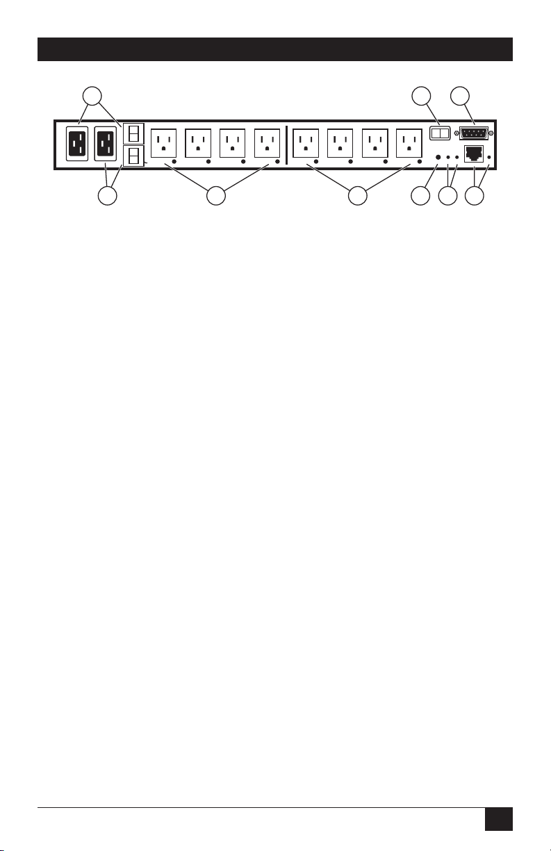
Figure 3-1: Back Panel Components - 8-Plug Models
(Model PS590A shown)
3.1. Back Panel Components - Models PS590A and PS590AE
As shown in Figure 3-1, models PS590A and PS590AE include the following
components:
Bus A - Power Inlet and Circuit Breaker: An AC inlet and circuit breaker
which supply power to the Circuit “A” outlets. Also includes Cable Keeper
(not shown.)
• PS590A: 100 to 120 VAC, IEC-320-C20 Inlet with 20-amp circuit breaker.
• PS590AE: 100 to 240 VAC, IEC-320-C20 Inlet with 16-amp circuit
breaker.
Bus B - Power Inlet and Circuit Breaker: An AC inlet and circuit breaker
which supply power to the Circuit “B” outlets. Includes same components
listed for Item 1 above. Also includes Cable Keeper (not shown).
Bus A - Switched Outlets and Indicator Lights: AC outlets that can be
switched On/Off, rebooted, or set to user-defined default state in response to
user commands.
• PS590A: Four (4) 100 to 120 VAC, NEMA 5-15R Outlets with indicator
lights. 20-amps total load per circuit.
• PS590AE: Four (4) 100 to 240 VAC, IEC-320-C13 Outlets with indicator
lights. 16-amps total load per circuit.
Bus B - Switched Outlets and Indicator Lights: AC outlets that can be
switched On/Off, rebooted, or set to user-defined default state in response to
user commands. Includes same components listed for Item 3 above.
17
Page 20

RACKMOUNT REMOTE POWER MANAGERS
Default Button: This button can be used to either reset the unit to default
parameters or manually toggle all plugs On or Off:
• Default Parameters: With the Master Power Switch set in the Off
position, press and hold the Default Button, then set the Master Power
Switch to the On position and release the Default Button. All user-defined
parameters will be reset to default values.
• Manual Plug Toggle: Press the Default Button and hold it down for
approximately three seconds. All Rackmount Remote Power Manager
outlets will be toggled On or Off.
NOTE
Section 5.3.1 describes how to disable the Default Button’s manual
plug control capabilities.
Unit Status Indicators: Two LED Indicators which function as follows:
• ON: Lights when power is applied to the Rackmount Remote Power
Manager.
• RDY: Flashes continuously when the Rackmount Remote Power Manager
is ready to receive commands.
Network Port and Activity Indicator: An RJ45 Ethernet Port
for connection to your TCP/IP network. The default IP address is
192.168.168.168; for more information, please refer to Section 5.3.4. The
Activity Indicator flashes to indicate activity at the Network Port.
Master Power Switch: Applies power to the Rackmount Remote Power
Manager. This switch must be “On” for the Rackmount Remote Power
Manager to function. You cannot use this switch to set the switched outlets’
on/off status.
COM/RS-232 Port: This DB9 COM/RS-232 serial port (DTE) is used for
connection to a local terminal or external modem, as described in Section 4.3.
Rackmounting Brackets (Not Shown): These brackets are used for
mounting the Rackmount Remote Power Manager in your equipment rack.
18
Page 21

CHAPTER 3: Overview
BUS
A
BUS
B
A-1 A-2 A-3 A-4 A-5 A-6 A-7 A-8
B-9 B-10 B-11 B-12 B-13 B-14 B-15 B-16
MAIN POWER
COM
10BaseT
ACTRDYONDEF
1
2
3
4
5
6
7
8
9
Figure 3-2: Back Panel Components - 16-Plug Models
(Model PS591A Shown).
3.2. Back Panel Components - Models PS591A and PS591AE
As shown in Figure 3-2, models PS591A and PS591AE include the following
components:
Bus A - Power Inlet and Circuit Breaker: An AC inlet and circuit breaker
which supply power to the Circuit “A” outlets. Also includes Cable Keeper
(not shown.)
• PS591A: 100 to 120 VAC, IEC-320-C20 Inlet with 20-amp circuit breaker.
• PS591AE: 100 to 240 VAC, IEC-320-C20 Inlet with 16-amp circuit
breaker.
Bus B - Power Inlet and Circuit Breaker: An AC inlet and circuit breaker
which supply power to the Circuit “B” outlets. Includes same components
listed for Item 1 above. Also includes Cable Keeper (not shown).
Bus A - Switched Outlets and Indicator Lights: AC outlets that can be
switched On/Off, rebooted, or set to user-defined default state in response to
user commands.
• PS591A: Eight (8) 100 to 120 VAC, NEMA 5-15R Outlets with indicator
lights. 20-amps total load per circuit.
• PS591AE: Eight (8) 100 to 240 VAC, IEC-320-C13 Outlets with indicator
lights. 16-amps total load per circuit.
Bus B - Switched Outlets and Indicator Lights: AC outlets that can be
switched On/Off, rebooted, or set to user-defined default state in response to
user commands. Includes same components listed for Item 3 above.
19
Page 22

RACKMOUNT REMOTE POWER MANAGERS
Default Button: This button can be used to either reset the unit to default
parameters or manually toggle all plugs On or Off:
• Default Parameters: With the Master Power Switch set in the Off
position, press and hold the Default Button, then set the Master Power
Switch to the On position and release the Default Button. All user-defined
parameters will be reset to default values.
• Manual Plug Toggle: Press the Default Button and hold it down for
approximately three seconds. All Rackmount Remote Power Manager
outlets will be toggled On or Off.
NOTE
Section 5.3.1 describes how to disable the Default Button’s manual
plug control capabilities.
Unit Status Indicators: Two LED Indicators which function as follows:
• ON: Lights when power is applied to the Rackmount Remote Power
Manager.
• RDY: Flashes continuously when the Rackmount Remote Power Manager
is ready to receive commands.
Network Port and Activity Indicator: An RJ45 Ethernet Port
for connection to your TCP/IP network. The default IP address is
192.168.168.168; for more information, please refer to Section 5.3.4. The
Activity Indicator flashes to indicate activity at the Network Port.
Master Power Switch: Applies power to the Rackmount Remote Power
Manager. This switch must be “On” for the Rackmount Remote Power
Manager to function. You cannot use this switch to set the switched outlets’
on/off status.
COM/RS-232 Port: This DB9 COM/RS-232 serial port (DTE) is used for
connection to a local terminal or external modem, as described in Section 4.3.
Rackmounting Brackets (Not Shown): These brackets are used for
mounting the Rackmount Remote Power Manager in your equipment rack.
20
Page 23

CHAPTER 4: Installation
4. Installation
4.1. Power Cable (and Cable Keeper) Connection
The Rackmount Remote Power Manager includes cable keepers, which are designed
to prevent the power supply cables from being accidentally disconnected from the
power manager. The 8-plug models (PS590A and PS590AE) feature cable keepers
that must be installed by the customer. The 16-plug models (PS591A and PS591AE)
include pre-installed cable keepers.
NOTE
The power manager’s master power switch must be on for the unit
to operate.
CAUTION
• Before attempting to install the power manager, review the
warnings and cautions listed on page 5.
• This device should be operated only with the type of power
source indicated on the instrument nameplate. If you are not sure
of the type of power service available, contact your local power
company.
• Maintain reliable grounding of the power manager. Pay particular
attention to supply connections when connecting to power strips,
rather than directly to the branch circuit.
4.1.1. Models PS590A and PS590AE
To install the cable keepers and power cables on the PS590A or PS590AE (8-plug
models), proceed as follows:
1. First, make sure that both of the power manager’s power cables are
disconnected from the power supply.
2. Next, loosen (but do not remove) the retaining screws located adjacent to the
power inlets.
3. Connect the power supply cables to the Power Manager’s Bus A and Bus B
power inlets, then slip a cable keeper under each supply cable so the notches
at the top of the keepers line up with each cable, and the two slots on the
bottom of the keepers slide under the loosened retaining screws.
4. Tighten the retaining screws to secure the cable keepers to the power
manager, and make certain that the cables are secure.
21
Page 24

RACKMOUNT REMOTE POWER MANAGERS
5. Refer to the Rackmount Remote Power Manager’s power rating nameplate,
and then connect the power supply cables to an appropriate power outlet.
Power ratings for models PS590A and PS590AE are as follows:
• PS590A: Two 100 to 120 VAC power circuits, 20 amps per circuit.
• PS590AE: Two 100 to 240 VAC power circuits, 16 amps per circuit.
4.1.2. Models PS591A and PS591AE
To install the cable keepers and power cables on the PS591A and PS591AE (16-plug
models), proceed as follows:
1. When attaching the power supply cables to the power manager, first move
the cable keepers out of the way, then plug the power cables securely into the
power inputs.
2. When the cables are in place, snap the cable keepers over each plug to secure
the cables to the power manager.
3. Refer to the Rackmount Remote Power Manager’s power rating nameplate,
and then connect the power supply cables to an appropriate power outlet.
Power ratings for models PS591A and PS591AE are as follows:.
• PS591A: Two 100 to 120 VAC power circuits, 20 amps per circuit.
• PS591AE: Two 100 to 240 VAC power circuits, 16 amps per circuit.
Once the power supplies are connected, set the master power switch to the “On”
position. After a brief pause, the plug indicators should switch on in sequence,
indicating that power is On.
4.2. Connection to Switched Outlets
Connect the power cord from each switched device to a switched AC outlet on the
power manager. When the power manager is turned on, the switched AC outlets
will be switched on. The power manager includes two separate power busses as
described below:
• PS590A and PS591A: Two 100 to 120 VAC power circuits, 15 amps per
outlet, 20 amps per circuit. Total 40 amps per unit.
• PS590AE and PS591AE: Two 100 to 240 VAC power circuits, 10 amps per
outlet, 16 amps per circuit. Total 32 amps per unit.
22
Page 25
CHAPTER 4: Installation
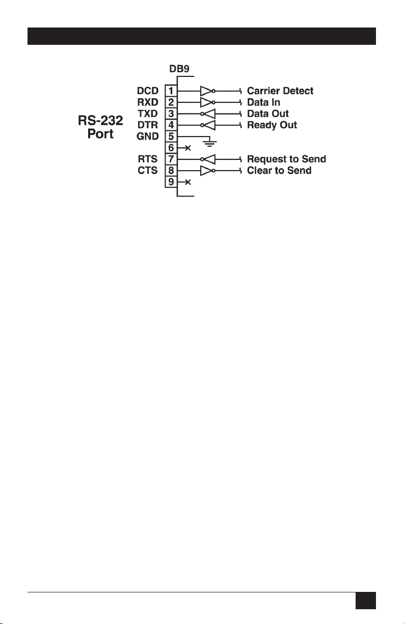
Figure 4-1: COM/RS-232 port interface.
4.3. Serial COM/RS-232 Port Connection
The COM port is a male, RS-232C DB9 connector, wired in a DTE configuration. In
the default state, the COM port is configured for 9600 bps, eight data bits, one stop
bit, and no parity. The COM port can be connected to either an external modem or
a local PC, but not to both items at the same time. Figure 4-1 shows the COM port
interface.
The Rackmount Remote Power Manager can be controlled via a TCP/IP network,
controlled by a local PC that communicates with the unit via cable, or controlled via
an external modem. To switch plugs or select parameters, commands are issued to
the power manager either via the network or via the COM/RS-232 port.
NOTES
• You don’t need to connect both the network and COM/RS-232
ports.
• The COM/RS-232 port can be connected to either a local PC or an
external modem.
23
Page 26

RACKMOUNT REMOTE POWER MANAGERS
4.3.1. Connecting a Local PC to the COM/RS-232 Port
Use a null-modem cable to connect your PC COM port to the power manager’s
COM/RS-232 port. Make sure that the serial port mode is set to console as described
in Section 5.3.2.
4.3.2. Connecting an External Modem to the COM/RS-232 Port
Use a standard AT® to modem cable to connect your external modem to the power
manager’s COM/RS-232 port. Make sure that the modem is initialized at the same
default parameters as the COM port. Be certain that the serial port mode is set to
modem as described in Section 5.3.2.
4.4. Connecting the Network Cable
The network port is an RJ-45 Ethernet jack for connection to a TCP/IP network.
Connect your 10BASE-T or 100BASE-T cable to the network port. The power
manager includes a default IP address (192.168.168.168) and a default subnet
mask (255.255.255.0). When installing the power manager in a working network
environment, we recommend that you define network parameters as described in
Section 5.3.4.
NOTE
The Rackmount Remote Power Manager features a 10BASE-T
interface. If you’re connecting a router switch to the Rackmount
Remote Power Manager, note the following: When connecting to
a 100BASE-T interface, most router switches will autosense to
determine if the device is 100BASE-T or 10BASE-T and configure
the network interface accordingly. If your router switch does not
autosense, the network interface port must be manually set to
10BASE-T.
24
Page 27

CHAPTER 5: Configuration
5. Configuration
Once you’ve installed the Rackmount Remote Power Manager, you’re ready for
configuration. First, select the command mode (system or user). Then you’ll learn
how to communicate with the Rackmount Remote Power Manager. Finally, you’ll
access the configuration menus and save configuration parameters.
5.1. System Mode and User Mode
To restrict access to sensitive command functions, the Rackmount Remote Power
Manager offers two command modes: system mode and user mode.
• System mode allows access to all configuration menus, switching functions, and
status screens. The system mode status screens show on/off conditions for all
switched outlets and list all currently defined system parameters.
• User mode allows access to switching and reboot commands but does not allow
access to configuration functions. Users may only issue commands to, or view
status of, the plugs that are specifically allowed by their password.
The power manager displays a password prompt when the unit is contacted via
the network port or the COM/RS-232 port. The password entered at this prompt
determines whether the unit will start up in system mode or user mode. If the system
password is entered, the system mode will be active. If a plug password is entered,
the user mode will be active. The system password is defined via the General
Parameters menus (Section 5.3.1), and the plug passwords are defined via the Plug
Parameters menus (Section 5.3.3).
NOTES
• If you want to restrict access to configuration menus, you must
define the system password.
• If the system password is not defined, the power manager will
always start up in system mode, allowing unprotected access to
configuration and switching functions.
• The password prompt will always be displayed when the power
manager is contacted via the Web Browser Interface. However,
if the system password is not defined, the prompt will not be
displayed when you access the power manager via the Text
Interface.
• When the power manager is contacted via the network, the
password prompt will also include a field for the user name. If
you have not defined a user name, leave this field blank, and only
the password is required to gain access to the power manager.
The user name prompt is not displayed when the power manager
is contacted via the Text Interface.
25
Page 28

RACKMOUNT REMOTE POWER MANAGERS
5.2. Communicating with the Rackmount Remote Power Manager
To configure the power manager or invoke command functions, you must first
connect to the power manager and access command mode. The power manager
offers two separate command interfaces: the Web Browser Interface and the Text
Interface. The Web Browser Interface allows you to contact the power manager via
a TCP/IP network by using a standard JavaScript® enabled Web browser (such as
Internet Explorer or Netscape Navigator®). The Text Interface consists of a series of
ASCII text menus, which you can access via a TCP/IP network, local PC, or modem.
The power manager also offers three different methods for accessing command
mode: via a network, via a local PC, or via an external modem.
NOTE
Configuration functions are only available when you have logged
into the power manager’s command mode using the system
password.
5.2.1. Accessing the Web Browser Interface
To use the Web Browser Interface, the power manager must be connected to a TCP/
IP network. Also, your PC must be equipped with a JavaScript enabled Web browser
(such as Internet Explorer or Netscape Navigator).
1. Start your JavaScript enabled Web browser.
2. Type the power manager’s IP address (default = http://192.168.168.168) into
the Web browser’s address bar, then press [
3. The power manager will display a prompt that asks for your name and
password.
a) User name: If you have not previously defined a user name, then this
field should be left blank. A user name is only required when one has
been defined via the General Parameters menu.
b) Password: Type in your system password or plug password, then click
on OK. Plug passwords do not permit access to configuration functions.
c) If the system password has not been defined, simply click on the OK
button without typing in a name or password. If you entered a valid
password, the Plug Status screen appears (see Figure 5-1.)
26
Enter].
Page 29

CHAPTER 5: Configuration
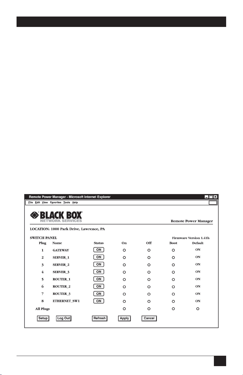
Figure 5-1: Plug Status Screen - Web Browser Interface
(8-Plug Model Shown)
Rackmount Remote Power Manager v1.41 Site ID: Black Box — Lawrence, PA
Plug | Name | Password | Status | Boot/Seq.Delay | Default |
----------------------------------------------------------------------------+
1 | GATEWAY | (undefined) | ON | 0.5 Secs | ON |
2 | SERVER_1 | (undefined) | ON | 1 min | ON |
3 | SERVER_2 | (undefined) | ON | 0.5 Secs | ON |
4 | SERVER_3 | (undefined) | ON | 0.5 Secs | OFF |
5 | ROUTER_1 | (defined) | ON | 0.5 Secs | ON |
6 | ROUTER_2 | (defined) | ON | 0.5 Secs | ON |
7 | ROUTER_3 | (defined) | ON | 0.5 Secs | OFF |
8 | ETHERNET_SW1 | (undefined) | ON | 0.5 Secs | ON |
----------------------------------------------------------------------------+
“/H” for help.
RPM>
Figure 5-2: Plug Status Screen - Text Interface
(8-Plug Model Shown)
27
Page 30

RACKMOUNT REMOTE POWER MANAGERS
5.2.2. Accessing the Text Interface
You can access the Text Interface via a network, a local PC, or a modem. To access
the Text Interface, your installation must include the following:
• Access via Network: The power manager must be connected to your TCP/
IP network, and your PC must include a communications program (such as
Hyperterminal).
• Access via Local PC: Your local PC must include a communications program.
• Access via Modem: An external modem must be connected to the power
manager’s COM/RS-232 port, and a phone line must be connected to the
external modem. Your PC must include a communications program.
To access command mode via the Text Interface, proceed as follows:
1. The power manager is transparent to parity and will accept 7- or 8-bit
characters, but it will always answer back at 8 bits, no parity. Make sure that
your communications program is set for the appropriate baud rate, parity, and
communications port.
a) Via Network: The power manager includes a default IP address
(192.168.168.168) that allows you to contact the unit from any network
node on the same subnet. When the power manager is installed in
a working network environment, we recommend that you redefine
the IP address, subnet mask, and gateway address as described in
Section 5.3.4.
i. Telnet to the power manager’s IP address. For example, if the IP
address is 192.168.168.168, then on a UNIX® system, the Telnet
command would be:
$ telnet 192.168.168.168 [Enter]
ii. If the Telnet connection is refused, this may mean that either the IP
security feature has denied the connection (see Section 5.3.4) or
that the power manager is operating on a 100BASE-T network that
does not autosense for 10BASE-T devices.
b) Via Local PC: Start your communications program and press [Enter].
Wait for the connect message, then proceed to step 2.
c) Via Modem: Start your communications program. Dial the external
modem connected to the power manager. Wait for the connect message,
then proceed to step 2.
28
Page 31

CHAPTER 5: Configuration
2. Password: If the system password has been defined, the power manager will
display the password prompt. Type in either the system password or plug
password, and press [Enter]. If the system password has not been defined,
the prompt will not display when the power manager is accessed via the Text
Interface. Instead, you’ll see the Plug Status screen described in Step 3.
NOTE
The password is case-sensitive.
3. If a valid system password or plug password is entered, the power manager
will display the Plug Status screen shown in Figure 5-2, followed by the
RPM> command prompt.
NOTE
The Plug Status screen does not display actual passwords. The
password column will read either “defined” or “undefined,”
depending upon whether or not the system or plug passwords are
defined.
29
Page 32

RACKMOUNT REMOTE POWER MANAGERS
5.3. Configuration Menus
As described in the sections that follow, the power manager’s configuration
parameters can be selected via the Web Browser Interface or via the Text Interface.
Although the Web Browser Interface and Text Interface provide two separate means
for selecting parameters, both interfaces allow access to essentially the same set of
parameters, and parameters selected via one interface will also apply to the other.
• Web Browser Interface: Click on the Setup button, shown in Figure 5-1 to
gain access to the configuration menus. A row of hyperlinks will appear along
the left edge of the screen. Click on the appropriate link to access the desired
menu.
NOTES
• Newly selected parameters will not be activated until you click on
the Apply button.
• Click on Switch Panel to return to the main status screen.
• Text Interface: Refer to the Help screen (/H), then type in the appropriate
command to access the desired menu. When the configuration menu appears,
type in the number or letter for the parameter that you want to define and follow
the instructions in the resulting submenu.
NOTE
To exit from a parameters menu, press the [Esc] key.
Section 5.3 describes the options and parameters that you can access via each of the
configuration menus.
NOTES
• Essentially the same selection of parameters and options are
available via both the Web Browser Interface and the Text
Interface.
• Configuration menus are only available when the system mode is
active. Configuration menus are not available if you log in using a
plug password.
30
Page 33
CHAPTER 5: Configuration
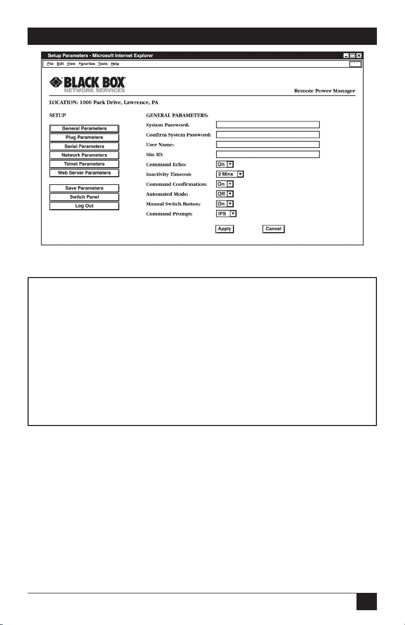
Figure 5-3: General Parameters Menu - Web Browser Interface.
GENERAL PARAMETERS:
1. System Password: (defined)
2. User Name: Black Box
3. Site ID: Black Box, Lawrence, PA
4. Command Echo: On
5. Inactivity Timeout: 2 Min
6. Command Confirmation: On
7. Automated Mode: Off
8. Manual Switch Button: On
9. Command Prompt RPM
A. Default Parameters
Enter Selection or <ESC> to Exit…
Figure 5-4: General Parameters Menu - Text Interface.
5.3.1. General Parameters Menus
The General Parameters menus allow you to select parameters such as the system
password, user name, site ID, modem commands, and other options. To access the
General Parameters Menus, proceed as follows:
• Web Browser Interface: Click the Setup button to access the Setup Menus,
and then click General Parameters. The General Parameters Menu will be
displayed as shown in Figure 5-3.
• Text Interface: Type /G and press [Enter]. The General Parameters Menu will
be displayed as shown in Figure 5-4.
31
Page 34

RACKMOUNT REMOTE POWER MANAGERS
The General Parameters menus allow you to define the following parameters:
• System Password: The Rackmount Remote Power Manager displays a
password prompt when you attempt to access command mode. When the
System Password is entered during login, the System Mode will be active,
allowing access to both switching functions and configuration menus. (The
password can be 4 to 16 characters long. The default password is undefined.)
NOTES
• If the system password is not defined, then the Rackmount
Remote Power Manager always starts up in system mode,
and configuration functions are then available to anyone who
accesses command mode.
• Passwords cannot include nonprintable characters, space
characters, asterisks (*) or quotation marks and cannot begin
with a forward slash (/) or backslash (\) character.
• User Name: (Optional) The user name allows you to set up an additional
layer of security for Web access to the command mode by requiring that users
correctly enter a name in addition to a password. (The user name can be 4 to 16
characters long. The default user name is undefined.)
NOTE
• The user name cannot include nonprintable characters, space
characters, asterisks (*) or quotation marks, and cannot begin
with a forward slash (/) or backslash (\) character.
• The user name is required only when you access the Rackmount
Remote Power Manager via the Web interface.
• Site ID: Defines a brief text message, which you can use to describe the
Rackmount Remote Power Manager’s installation location. (The installation
location can be up to 32 characters long, and the default location is undefined.)
NOTE
The Site ID message cannot include nonprintable characters, space
characters, asterisks (*) or quotation marks, and cannot begin with
a forward slash (/) or backslash (\) character.
• Command Echo: Enables or disables command echo. When enabled,
ASCII commands sent via the Text Interface to the Rackmount Remote Power
Manager will be echoed back, allowing keystrokes to be displayed. This feature
applies only to the Text Interface and has no visible effect on the Web Browser
Interface. (The default value is On.)
32
Page 35

CHAPTER 5: Configuration
• Inactivity Timeout: Determines how long the Rackmount Remote Power
Manager will wait for additional commands during periods of inactivity. When
the timeout period elapses, the user will be disconnected from command mode.
(The default timeout is 2 minutes.)
• Command Confirmation: When enabled, the Rackmount Remote Power
Manager displays a confirmation prompt before executing certain commands.
When disabled, the prompt is suppressed and commands are executed
immediately. (The default value is on or enabled.)
• Automated Mode: When enabled, the Rackmount Remote Power Manager
executes on, off, boot, and exit commands without displaying a confirmation
prompt, status screen, or confirmation messages. This allows the Rackmount
Remote Power Manager to be controlled by a device that generates commands
to control switching without human intervention. For more information, please
refer to Section 6.4. (The default value is Off.)
NOTE
When this option is enabled, most security functions are
suppressed, and users are able to access configuration menus and
control plugs without entering a password. If security is a concern
and the automated mode is required, we recommend using the IP
security feature (see Section 5.3.4) to restrict access.
• Manual Switch Button: Enables and configures the Default Button’s manual
plug control function, but does not effect the Default Button’s ability to reset
parameters to default values. (The default value is On.)
• Off: Disables the manual plug control function.
• On: Enables the manual plug control. When the Default Button is pressed
and held for three seconds, all outlets will be toggled On or Off.
• Command Prompt: Selects the prompt that is sent when the Rackmount
Remote Power Manager is contacted via the Text Interface. The default prompt
is RPM.
• Default Parameters: Resets the Rackmount Remote Power Manager to
default parameters. All menu-selected parameters, including port names and
passwords, are cleared. This option is only available via the Text Interface.
NOTE
If you invoke this function via the network port, the IP address is
not reset until you break the connection to the network port. If
you invoke this function via the console port or modem port, the IP
address resets immediately.
33
Page 36
RACKMOUNT REMOTE POWER MANAGERS
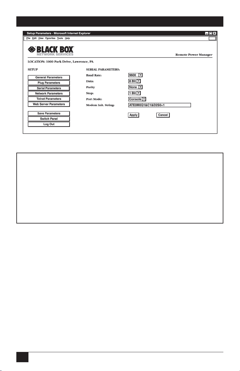
Figure 5-5: Serial Parameters Menu - Web Browser Interface
SERIAL PARAMETERS:
1. Baud Rate: 9600
2. Data: 8 Bit
3. Parity: None
4. Stop: 1 Bit
5. Port Mode: Console
6. Modem Init. Str: ATE0M0Q1&C1&D2S0=1
Enter selection,
Press <ESC> to return to previous menu…
Figure 5-6: Serial Parameters Menu - Text Interface
5.3.2. Serial (Console) Port Parameters Menus
The Serial Parameters menus define baud rate, data, parity, stop, port mode, and
modem initialization string. To access the Serial Parameters Menu, proceed as
follows:
• Web Browser Interface: Click the Setup Button to access the Setup Menus, and
then click Serial Parameters. The Serial Parameters Menu will be displayed as
shown in Figure 5-5.
• Text Interface: Type /C and press [Enter]. The Serial Parameters Menu will
be displayed as shown in Figure 5-6.
34
Page 37

CHAPTER 5: Configuration
The Serial Parameters menu is used to define the following parameters:
NOTE
When baud rate, data bits, parity, or stop bits are changed via the
console port, new values will not be applied until you exit and then
reenter the command mode.
• Baud Rate: The data speed setting. (The default value is 9600 bps.)
• Data: The number of data bits. (The default value is 8 Bit.)
• Parity: The console port parity. (The default value is None.)
• Stop: The stop bits setting. (The default value is 1 Bit.)
• Port Mode: Sets up the serial console port for use with either a local PC
(“console”) or external modem (“modem”). When port mode is set to modem,
the initialization string will be sent every 15 minutes. (The default value is
console.)
• Modem Initialization String: This is a command string (up to 32 characters
long; the default is ATE0M0Q1& C1& D2S0=1) that is sent out of the serial
console port to initialize an external modem. If the serial port mode is set to
“console,” the modem initialization string is not sent. For more information on
initialization commands, refer to your modem’s users’ guide.
35
Page 38
RACKMOUNT REMOTE POWER MANAGERS
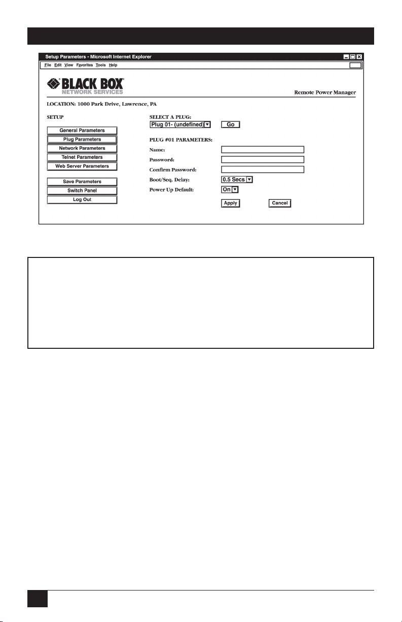
Figure 5-7: Plug Parameters Menu - Web Browser Interface
PLUG #1 PARAMETERS:
1. Plug Name: Server_1
2. Password: (undefined)
3. Boot/Seq. Delay: 0.5 Secs
4. Power Up Default: On
Enter Selection,
Press <ESC> to Exit…
Figure 5-8: Plug Parameters menu - Text Interface
5.3.3. Plug Parameters Menus
The Plug Parameters menus define plug names, plug passwords, and boot/sequence
delay times for each of the Rackmount Remote Power Manager’s switched AC
outlets.
• Web Browser Interface: Click the Setup Button to access the configuration
menus, then click Plug Parameters. The Plug Parameters Menu will be
displayed as shown in Figure 5-7.
• Text Interface: Type /P n and then press [Enter] (where n is the number or
name of the plug you wish to configure.) The Plug Parameters Menu will be
displayed as shown in Figure 5-8.
Note that in this case, the major difference between the Web Browser Interface and
the Text Interface is that the Web Browser Interface allows you to select parameters
for all plugs from a single menu, whereas the Text Interface includes a separate menu
for each plug.
36
Page 39

CHAPTER 5: Configuration
The Plug Parameters menu is used to define the following parameters:
• Plug Name: Assigns a name to the plug. (The name can be up to 16 characters
long, and the default name is undefined.)
NOTE
The plug name cannot begin with a number, a dash (-), an
underscore (_), a slash (/), or a backslash (\). Plug names cannot
contain nonprintable characters, colons (:), plus signs (+), spaces,
or quotation marks (“ ”).
• Plug Password: Assigns a password to the corresponding plug. When you
enter this password at login, you can issue commands to this plug and any
other Rackmount Remote Power Manager plug that shares the same password.
(The password can be up to 16 characters long, and the default password is
undefined.)
NOTES
• The Plug Password does not allow access to configuration
functions.
• Passwords cannot begin with the forward slash character (/)
or backslash character (\), and cannot contain nonprintable
characters, asterisks (*), spaces, or quotation marks.
• Boot/Sequence Delay: When more than one plug is switched on/off or a reboot
cycle is initiated, the boot/sequence delay determines how much time elapses
between switching operations. (The default boot/seq. delay is 0.5 seconds.)
• Power Up Default: Determines how this plug will react when the Default
command (/D) is invoked, or after power to the unit has been interrupted and
restored. When the Default command is invoked, or power is restored, the
Rackmount Remote Power Manager will automatically switch each plug on or
off as specified by the power-up default. (The default setting is on.)
NOTE
If you have accessed command mode using the System password,
the Default command will apply to all switched plugs. If you
have accessed command mode using a plug password, then
the command will only be applied to plugs that share the same
password entered at login.
37
Page 40

RACKMOUNT REMOTE POWER MANAGERS
Plug Passwords and Co-Location Features
The plug passwords allow you to determine which plugs an individual user will be
permitted to control. When a plug password is entered at the login prompt, the user
will be able to issue switching and reboot commands for the corresponding plug and
every other plug that shares this same password.
For example, if the password “switch” is defined for plugs 1, 2, and 3, then a user
who logs into command mode using the password “switch” will only be allowed to
issue commands to plugs 1, 2, and 3, and will not be allowed to issue commands to
the remaining plugs.
NOTE
Plug passwords do not allow access to configuration menus, and
users are only allowed to view the status of plugs permitted by their
password.
The Boot/Sequence Delay Period
The boot/sequence delay value applies differently for reboot operations as opposed
to simple on/off operation. See below for more information.
1. Reboot Cycles:
a) Single Plug: The boot/sequence delay determines how long the plug
remains off before it switches back on again.
b) Several Plugs: The boot/sequence delay determines how long the plug
will remain in the “off” condition and how long the Rackmount Remote
Power Manager pauses before proceeding to the next plug specified by
the reboot command.
2. On/Off Switching: The boot/sequence delay determines how long the
Rackmount Remote Power Manager pauses before proceeding to the next
plug specified by the On command.
Examples:
Assume that the boot/sequence delays for each plug are set as follows: Plug 1 = 1
second, Plug 2 = 2 seconds, Plug 3 = 5 seconds, Plug 4 =1 minute,
Plug 5 =1 second.
38
Page 41

CHAPTER 5: Configuration
If an “On” command is applied to plugs 1–5, the Rackmount Remote Power
Manager responds as follows:
1. Turn on plug 1, wait 1 second.
2. Turn on plug 2, wait 2 seconds.
3. Turn on plug 3, wait 5 seconds.
4. Turn on plug 4, wait 1 minute.
5. Turn on plug 5.
If a reboot command is applied to plug 3, the Rackmount Remote Power Manager
responds as follows:
1. Turn off plug 3, wait 5 seconds, turn on plug 3.
If a reboot command is applied to plugs 1–5, the Rackmount Remote Power Manager
will respond as follows:
1. Turn off all five plugs (short delay between plugs).
2. Wait 1 second, turn on plug 1, wait 1 second.
3. Wait 2 seconds, turn on plug 2, wait 2 seconds.
4. Wait 5 seconds, turn on plug 3, wait 5 seconds.
5. Wait 1 minute, turn on plug 4, wait 1 minute.
6. Wait 1 second, turn on plug 5.
39
Page 42

RACKMOUNT REMOTE POWER MANAGERS
5.3.4. Network Parameters Menus
The Network Parameters menus select the IP address and other network parameters.
To access the Network Parameters menus, proceed as follows:
• Web Browser Interface: Click the Setup button to access the Setup menus,
and then click Network Parameters. The Network Parameters menu will be
displayed as shown in Figure 5-9.
• Text Interface: Type /N and press [Enter]. The Network Parameters menu will
be displayed as shown in Figure 5-10.
NOTES
• Although the Web Browser Interface and Text Interface both allow
configuration of the same network parameters, note that for the
Text Interface, the IP security feature is configured via a separate
submenu as described in the following section.
• Settings for network parameters depend on the configuration of
your individual network. Contact your network administrator for
appropriate settings.
The Network Parameters menus are used to define the following parameters. Except
where noted, all parameters listed here are available via both the Web Browser
Interface and the Text Interface.
• IP Address: Defines the Rackmount Remote Power Manager’s IP address.
(The default IP address is 192.168.168.168.)
• Subnet Mask: Defines the Rackmount Remote Power Manager’s subnet mask.
(The default subnet mask is 255.255.255.0.)
• Gateway Address: Defines the Rackmount Remote Power Manager’s gateway
address. (The default gateway address is undefined.)
• Send MSS: Defines the maximum segment size that will be sent by the
Rackmount Remote Power Manager. (The default maximum segment size
is 536.)
• IP Security: Sets up the IP Security feature. Please refer to the next page for a
detailed description of the IP Security feature.
• MAC Address: Displays the Rackmount Remote Power Manager’s MAC
address. Please note that this item only displays the assigned MAC address
and can’t be used to redefine the address. Note that the MAC Address is not
displayed by the Web Browser Interface.
40
Page 43

CHAPTER 5: Configuration
Figure 5-9: Network Parameters Menu - Web Browser Interface
NETWORK PARAMETERS:
1. IP Address: 65.106.93.103
2. Subnet Mask: 255.255.255.0
3. Gateway Address: 65.106.93.97
4. Send MSS: 536
5. IP Security
MAC Address: 00-09-9b-00-90-f6
Enter Selection or <ESC> to Exit…
Figure 5-10: Network Parameters Menu - Text Interface
41
Page 44

RACKMOUNT REMOTE POWER MANAGERS
IP Security Feature
The IP Security feature can be used to restrict unauthorized IP addresses from
establishing a connection with the power manager. In the default state, the power
manager accepts incoming IP connections from all hosts. To configure the IP security
feature, proceed as follows.
1. Access the IP Security Menu.
a) Web Browser Interface: The IP Security feature is configured using
the fields at the bottom of the Network Parameters menu as shown in
Figure 5-9.
b) Text Interface: Go to the Network Parameters menu (/N), type 5, then
press [Enter]. The IP Security menu will appear (see Figure 5-11).
2. The IP Security menu lists five IP security “masks” and the selected permit/
deny action for each mask.
a) Each security mask prompt defines a specific IP address or range of
addresses. Each mask action prompt defines the permit/deny action for
the corresponding mask.
b) Masks are listed in order of ascending priority; mask 1 has the lowest
priority, mask 5 has the highest priority.
c) Masks have a cumulative effect; high-priority masks supersede the effect
of lower-priority masks.
d) Each IP address consists of a series of four 8-bit numbers. The number
255 is a wild card.
IP SECURITY:
1. Security Mask #1: (undefined)
2. Mask #1 Action: Permit
3. Security Mask #2: (undefined)
4. Mask #2 Action: Permit
5. Security Mask #3: (undefined)
6. Mask #3 Action: Permit
7. Security Mask #4: (undefined)
8. Mask #4 Action: Permit
9. Security Mask #5: (undefined)
10. Mask #5 Action: Permit
Enter selection,
Press <ESC> to return to previous menu ...
Figure 5-11: IP Security Menu - Text Interface
42
Page 45

CHAPTER 5: Configuration
Example 1: Deny access to all hosts except 192.1.1.5:
Security Mask #1: 255.255.255.255 Mask #1 Action: Deny
Security Mask #2: 192.1.1.5 Mask #2 Action: Permit
Since 255 is a wild card, mask #1 blocks all IP addresses. Mask #2 then specifically
grants access to 192.1.1.5 only.
Example 2: Allow access only by addresses that begin with 192.
Security Mask #1: 255.255.255.255 Mask #1 Action: Deny
Security Mask #2: 192.255.255.255 Mask #2 Action: Permit
Since 255 is a wild card, mask 1 blocks all IP addresses. Mask 2 then grants access to
all addresses that begin with 192.
Example 3: Allow access only by addresses that begin with 192, deny access to
192.1.1.5.
Security Mask #1: 255.255.255.255 Mask #1 Action: Deny
Security Mask #2: 192.255.255.255 Mask #2 Action: Permit
Security Mask #3: 192.1.1.5 Mask #3 Action: Deny
Since 255 is a wild card, mask 1 blocks all IP addresses. Mask 2 then grants access
to all addresses that begin with 192. Finally, mask 3 specifically blocks access by
192.1.1.5.
NOTE
• Mask #5 has priority over the other four masks. If mask #5 is
set to deny access by “255.255.255.255” (all wild cards), you will
not be able to access the Rackmount Remote Power Manager’s
command mode via network. In this case, access will only be
allowed via a local PC or external modem connected to the
Rackmount Remote Power Manager’s console port.
• When using the wild card address “255.255.255.255”, make
certain that at least one higher-priority mask permits access by
your IP address.
43
Page 46

RACKMOUNT REMOTE POWER MANAGERS
Figure 5-12: Telnet Parameters Menu - Web Browser Interface
TELNET PARAMETERS:
1. Service: On
2. Telnet Port #: 23
Enter Selection or <ESC> to Exit…
Figure 5-13: Telnet Parameters Menu - Text Interface
5.3.5. Telnet Parameters Menus
The Telnet Parameters menus enable/disable Telnet access to the Rackmount Remote
Power Manager command mode and select the TCP port for Telnet connections.
• Web Browser Interface: Click the Setup button to access the configuration
menus, then click on Telnet Parameters to display the menu shown in
Figure 5-12.
• Text Interface: Type /T and press [Enter]. The Telnet Parameters menu
appears as shown in Figure 5-13.
The Telnet Parameters menus define the following parameters. All parameters listed
here are available via both the Web Browser Interface and Text Interface.
• Service: Enables/disables Telnet communication with the Rackmount Remote
Power Manager. When this item is set to “Off,” users cannot contact the
Rackmount Remote Power Manager via Telnet. (The default value is On.)
• Telnet Port Number: Selects the TCP/ IP port number that is used for Telnet
connections. (The default port number is 23.)
44
Page 47

CHAPTER 5: Configuration
Figure 5-14: Web Server Parameters Menu - Web Browser Interface
WEB SERVER:
1. Service: On
2. Port #: 80
Enter Selection or <ESC> to Exit…
Figure 5-15: Web Server Parameters Menu - Text Interface
5.3.6. Web Server Parameters Menus
The Web Server Parameters menus configure the internal Web server, which lets you
operate the Rackmount Remote Power Manager via the Web Browser Interface.
• Web Browser Interface: Click the Setup button to access the configuration
menus, then click Web Server Parameters. The Web Server Parameters menu
will be displayed as shown in Figure 5-14.
• Text Interface: Type /W and press [Enter]. The Web Server Parameters menu
will be displayed as shown in Figure 5-15.
The Web Server Parameters menu defines the following parameters. All parameters
listed here are available via both the Web Browser Interface and Text Interface.
• Service: Enables/disables the Rackmount Remote Power Manager’s Web
server. When the Web server is disabled, you cannot communicate via the Web
Browser Interface. (The default value is On.)
• Port Number: Sets the TCP/IP port number. Set the port number to any
valid number except 23; this is because 23 is the default port number used for
communication with the Rackmount Remote Power Manager via Telnet. (The
default port number is 80.)
45
Page 48

RACKMOUNT REMOTE POWER MANAGERS
5.4. Save Configuration Parameters
The Rackmount Remote Power Manager offers two methods for saving parameters:
saving to memory and saving to an ASCII file. Saving parameters to memory
ensures that your user-defined configuration remains intact if power to the
Rackmount Remote Power Manager is temporarily interrupted.
To Save Parameters via the Web Browser Interface, go to the Plug Status Screen
(Figure 5-1) and click the Setup button. When the configuration menu appears, click
on the Save Parameters link on the left hand side of the screen.
To save Parameters via the Text Interface, type /E and press [Enter]. To restore
parameters via the Text Interface, type /R, press [Enter] and follow the instructions
in the resulting submenu.
In addition to saving parameters to memory, you can also save parameters to an
external ASCII file. Saving parameters to an ASCII file allows you to create a
“backup” of your currently defined configuration. As described in Chapter 7, this
provides quick recovery if the Rackmount Remote Power Manager is accidentally
reset to default parameters. It also allows you to copy parameters to other
Rackmount Remote Power Managers when several Rackmount Remote Power
Managers need to be configured with the same parameters.
NOTES
• After new parameters are applied, the Rackmount Remote Power
Manager displays a “Save” prompt. In the Web Browser Interface,
this prompt appears when you leave the configuration menus. In
the Text Interface, the prompt appears when you disconnect from
command mode. At this point, you can save new parameters,
continue without saving, or revert to previously saved parameters.
• If parameters are not saved, and if power to the Rackmount
Remote Power Manager is interrupted, newly defined parameters
are lost. When power is restored, the Rackmount Remote Power
Manager is then configured with the previously saved parameters.
46
Page 49
CHAPTER 6: Operation
6. Operation
As discussed in Chapter 5, the Rackmount Remote Power Manager offers two
separate command interfaces: the Web Browser Interface and the Text Interface.
Both interfaces offer essentially the same command options and features, and
parameters defined via the Web Browser Interface also apply when communicating
via the Text Interface (and vice versa).
6.1. Operation via the Web Browser Interface
When using the Web Browser Interface, all switching commands are invoked via the
Plug Status screen (Switch Panel), which also displays the status of the Rackmount
Remote Power Manager’s five or sixteen switched outlets.
6.1.1. The Plug Status Screen (Switch Panel) - Web Browser Interface
When you log onto the Rackmount Remote Power Manager command mode using
the Web Browser Interface, the first screen that appears after login is the Plug Status
menu or Switch Panel. The Plug Status menu (Figures 6-1) lists the current on/off
status of the Rackmount Remote Power Manager’s switched outlets and provides a
series of buttons that are used to control on/off/boot outlet switching.
Figure 6-1: Plug Status Menu - Web Browser Interface
(8-Plug Model Shown)
47
Page 50

RACKMOUNT REMOTE POWER MANAGERS
6.1.2. Controlling Power - Web Browser Interface
To invoke on/off/boot commands or view plug status via the Web Browser Interface:
1. Access the Rackmount Remote Power Manager’s command mode as
described in Section 5.2.1.
2. When the Plug Status menu (Figure 6-1) appears, note that the screen
includes a status field and on/off/boot controls for each of the Rackmount
Remote Power Manager’s switched AC outlets.
NOTES
• When boot/on/off operations are initiated, boot/sequence delay
times apply as described in Section 5.3.3.
• Users who log into command mode using a plug password are
only allowed to issue commands to the plugs allowed by that
password.
3. Switching Plugs On: To switch one or more plugs on, click the On button
next to the desired plug(s), then click on the Apply button.
a) To switch all plugs on, click the On button in the “All Plugs” row, then
click on Apply.
b) The Rackmount Remote Power Manager will display a screen that
indicates that the switching operation is in progress, and then return to
the updated Plug Status screen (which should now show the selected
plugs in the On position).
4. Switching Plugs Off: To switch one or more plugs off, click the Off button
next to the desired plug(s), then click on the Apply button.
a) To switch all plugs off, click the Off button in the “All Plugs” row, then
click on Apply.
b) The Rackmount Remote Power Manager will display a screen that
indicates that the switching operation is in progress, and then return to
the updated Plug Status screen (which should now show the selected
plugs in the Off position).
48
Page 51

CHAPTER 6: Operation
5. Reboot Cycle: To initiate a reboot cycle, click the Boot button next to the
desired plug(s), then click on the Apply button.
a) To reboot all plugs, click the Boot button in the “All Plugs” line, then
click on Apply.
b) The Rackmount Remote Power Manager displays a screen that indicates
that the reboot cycle is in progress. It then returns to the Plug Status
menu (which should now show the selected plugs in the On position.)
6. Power Up Default: To set all plugs to their user-defined power up default
on/off status, click the Default button in the All Plugs row and then click on
Apply.
NOTE
In order for the Power Up Default command to function, power
up default values for each desired plug must first be defined as
described in Section 5.3.4.
49
Page 52

RACKMOUNT REMOTE POWER MANAGERS
Network Boot Bar v1.41c Site ID: Black Box - Lawrence, PA
Display Configuration
/H Display Help Screen /G View/Set General Parameters
/S Display Plug Status /P [n] View/Set Plug Parameters
/SN Display Network Status /C View/Set Serial Parameters
/N View/Set Network Parameters
Control /T View/set Telnet Parameters
/D Set Plugs to Default /W View/Set Web Server
/Boot <n> Boot Plug n /E Save Parameters
/On <n> Turn On Plug n /R Recall Parameters
/Off <n> Turn Off Plug n /DL Download Parameters to File
/X Exit/Disconnect
Utilities
+------------------------------------+ /I Reset Network Interface
| [n] = optional plug name or number | /U Upgrade Firmware
| <n> = required plug name or number |
| n+n or n n = plug n and plug n |
| n:n = plug n through plug n |
| * = all plugs |
| ,y = bypass “Sure? (y/n)” |
+------------------------------------+
RPM>
Figure 6-2: The Remote Power Manager Help Screen - Text Interface
6.2. Operation via the Text Interface
When using the Text Interface, all switching functions are controlled by simple
ASCII commands. ASCII commands are also used to display status screens
and allow you to log out of command mode. The Text Interface also includes a
Help menu, which summarizes all available Rackmount Remote Power Manager
commands. To display the Text Interface Help menu (Figure 6-2), type /H and
press [Enter].
6.2.1. The Plug Status Screen - Text Interface
When you login to the Rackmount Remote Power Manager command mode using
the Text Interface, the first screen that appears after login is the Plug Status screen.
The Plug Status screen (Figure 6-3) lists the current status of the Rackmount Remote
Power Manager’s switched AC outlets and displays the firmware version and
currently defined Site ID message.
Normally, the Plug Status screen redisplays each time a command successfully
executes. However, you can enable the automated mode (see Section 6.4) to
suppress the Plug Status screen’s display after each command.
50
Page 53

CHAPTER 6: Operation
Rackmount Remote Power Manager v1.41 Site ID: Black Box — Lawrence, PA
Plug | Name | Password | Status | Boot/Seq.Delay | Default |
----------------------------------------------------------------------------+
1 | GATEWAY | (undefined) | ON | 0.5 Secs | ON |
2 | SERVER_1 | (undefined) | ON | 1 min | ON |
3 | SERVER_2 | (undefined) | ON | 0.5 Secs | ON |
4 | SERVER_3 | (undefined) | ON | 0.5 Secs | OFF |
5 | ROUTER_1 | (defined) | ON | 0.5 Secs | ON |
6 | ROUTER_2 | (defined) | ON | 0.5 Secs | ON |
7 | ROUTER_3 | (defined) | ON | 0.5 Secs | OFF |
8 | ETHERNET_SW1 | (undefined) | ON | 0.5 Secs | ON |
----------------------------------------------------------------------------+
“/H” for help.
RPM>
Figure 6-3: Plug Status Screen - Text Interface
(8-Plug Model Shown)
6.2.2. Controlling Power - Text Interface
These commands described in this section can be used to boot or toggle the on/off
status of the Rackmount Remote Power Manager’s switched plugs or to set plugs to
user-defined default status. Plugs can be specified by name or by number.
NOTES
• Wait for the RPM> prompt to appear before entering commands.
The prompt will not reappear until the previous command is
complete.
• Commands are not case sensitive. All commands are invoked by
pressing [Enter].
• Users who log into command mode using a plug password are
only allowed to issue commands to the plugs permitted by that
password.
• If command confirmation is enabled, the Rackmount Remote
Power Manager displays the status screen after the boot/on/off
commands are successfully completed.
• When boot/on/off operations are initiated, boot/sequence delay
times will be applied as described in Section 5.3.3.
51
Page 54

RACKMOUNT REMOTE POWER MANAGERS
To switch plugs or initiate a boot cycle:
1. Switching Plugs On: To power-on a plug, type /ON n (where n is the
number or name of the desired plug) and press [Enter]. For example:
/ON 1 or /ON ROUTER
2. Switching Plugs Off: To power-off a plug, type /OFF n (where n is the
number or name of the desired plug) and press [Enter]. Note that the /OFF
command can also be entered as /OF. For example:
/OFF 2 or /OF ROUTER
3. Reboot Cycle: To initiate a boot cycle, type /BOOT n (where n is a the
number or name of the desired plug) and press [Enter]. Note that the /BOOT
command can also be entered as /BO. For example:
/BOOT 1 or /BO ATMSWTCH
4. Suppress Prompt: To execute a Boot/On/Off command without displaying
the “Sure?” prompt, include the “,Y” option at the end of the command line.
For example:
/ON ROUTER,Y or /BOOT 2,Y
5. Power Up Default: Type /D and press [Enter]. Plugs will be set to their
default on/off status, which is defined using the Plug Parameters menu (see
Section 5.3.3).
NOTES
• When you have accessed command mode using the system
password, the Default command will be applied to all plugs.
• When you have accessed command mode using a plug (user)
password, the Default command will only be applied to the plugs
permitted by the password.
52
Page 55

CHAPTER 6: Operation
6.2.3. Applying Commands to Several Plugs
As described below, Boot/On/Off commands can be applied to only one switched AC
outlet or to an assortment of outlets.
NOTE
When Boot/On/Off operations are initiated, Boot/Sequence Delay
times apply as described in Section 5.3.3.
1. To apply an On/Off /Boot command to several plugs, enter the numbers or
names for the plugs, separated by a plus sign (+). For example, to switch
plugs 1, 4, and 5 off, enter the following:
/OFF 1+4+5 [Enter]
2. To apply a command to a series of Rackmount Remote Power Manager plugs,
enter the number for the plugs that mark the beginning and end of the series,
separated by a colon. For example, to switch plugs 1 through 3 on, enter the
following:
/ON 1:3 [Enter]
3. To apply a command to all plugs, enter an asterisk in place of the name or
number. For example, to boot all plugs, enter the following:
/BO* [Enter]
53
Page 56

RACKMOUNT REMOTE POWER MANAGERS
6.3. Logging Out of Command Mode
When you have finished communicating with the Rackmount Remote Power
Manager, always disconnect using either the Logout button (Web Browser Interface)
or /X command (Text Interface) rather than by simply closing your browser window
or communications program.
Disconnecting using the Logout button or /X command ensures that the Rackmount
Remote Power Manager has completely exited from command mode and is not
waiting for the inactivity timeout period to elapse before allowing additional
connections.
6.4. The Automated Mode
The automated mode allows the Rackmount Remote Power Manager to execute
switching and reboot commands without displaying menus or generating response
messages. Automated mode allows the Rackmount Remote Power Manager to
be controlled by a device that can generate commands to control power-switching
functions without human intervention.
When the automated mode is enabled, the /ON, /OFF, /BOOT, and /X commands
are executed without a “Sure?” confirmation prompt and without command response
messages; the only reply to these commands is the RPM> prompt, which is displayed
when the command is complete.
NOTES
• Automated mode is designed primarily for users who want to
send ASCII commands to the Rackmount Remote Power Manager
without operator intervention, so it does not specifically apply
to the Web Browser Interface. When the automated mode is
enabled, the Web Browser Interface can still be used to invoke
On/Off/Boot commands.
• When automated mode is enabled, all Rackmount Remote
Power Manager password security functions are disabled, and
users can access system-level command functions (including
the configuration menus) and control plugs without entering a
password.
• If you need to enable the automated mode but want to restrict
network access to Rackmount Remote Power Manager
configuration menus, enable and configure the IP security
function as described in Section 5.3.4.
54
Page 57

CHAPTER 6: Operation
To enable/disable the automated mode, access the General Parameters menu (see
Section 5.3.1) and set the “Automated Mode” option to “On.” When the automated
mode is enabled, Rackmount Remote Power Manager functions change as follows:
1. All Password Security Suppressed: When a user attempts to access the
command mode, the password prompt does not display at either the console
port or network port. Unless specifically restricted by the IP security function,
all users can access both switching and configuration functions, and all
commands are immediately accepted without entering a password.
2. Status Screens Suppressed: The status screens do not automatically
display after commands are successfully executed. Note however, that the /S
command can still be invoked to display the status screen, if needed.
3. “Sure?” Prompt Suppressed: All commands are executed without
prompting for user confirmation.
4. Error Messages Suppressed: If you press the [Enter] key without entering
a command, the Rackmount Remote Power Manager does not respond
with the “Invalid Command” message. However, an error message is still
generated if commands are invoked using invalid formats or arguments.
All other status display and configuration commands still function as normal.
6.5. Manual Operation
In addition to the command-driven functions available via the Web Browser Interface
and Text Interface, the Rackmount Remote Power Manager’s switched plugs can
also be toggled on and off manually. To manually toggle plugs on or off, press the
Default button and hold it down for approximately three seconds.
If desired, the manual switch button option (accessed via the General Parameters
menu) can be used to completely disable the Default button’s manual plug control
capability as described in Section 5.3.1.
NOTE
When the Default button is used to toggle outlets On or Off, Boot/
Sequence Delay times will be applied.
55
Page 58

RACKMOUNT REMOTE POWER MANAGERS
7. Saving and Restoring
Configuration Parameters
After the Rackmount Remote Power Manager is properly configured, parameters can
be downloaded and saved as an ASCII text file on your local or remote PC. Later,
if the configuration is accidentally altered, the file with the saved parameters can
be uploaded to automatically reconfigure the Rackmount Remote Power Manager
without manually assigning each parameter.
You can also upload saved parameters to other Rackmount Remote Power Managers.
This allows rapid setup when several Rackmount Remote Power Managers are
configured with the same parameters.
You can perform the Save Parameters procedure from any terminal emulation
program (for example, ProComm, Crosstalk®, HyperTerminal, etc.) that allows
downloading of ASCII files.
NOTES
• Although this function is available only via the text interface,
parameters defined via the Web-browser interface are also sent to
the ASCII file.
• The current On/Off status of each outlet will not be saved or
restored.
7.1. Sending Parameters to a File
1. Start your communications program and access the Rackmount Remote
Power Manager’s command mode using the system-level password.
2. When the command prompt appears, type /DL and press [Enter]. The
Rackmount Remote Power Manager prompts you to prepare your
communications program. Set up your communications program to receive
an ASCII download, and specify a name for the file that will receive the
saved parameters (for example, RPM.PAR).
3. When the communications program is ready to receive the file, return to the
Rackmount Remote Power Manager’s command mode, and press [Enter] to
proceed.
4. The Rackmount Remote Power Manager sends a series of ASCII command
lines that specify the currently selected parameters.
56
Page 59

CHAPTER 7: Saving and Restoring Configuration Parameters
7.2. Restoring Saved Parameters
This section describes the procedure for using ProComm to send saved parameters to
the Rackmount Remote Power Manager.
NOTE
Parameters saved to an ASCII file can only be restored via the text
interface. This procedure cannot be performed via the Web-browser
interface.
1. Start your communications program and access the Rackmount Remote
Power Manager’s command mode via the text interface as described in
Section 5.2.2.
2. If the password prompt appears, type in your system password and
press [Enter].
3. Configure your communications program to upload an ASCII text file.
4. Upload the file with the saved parameters. If necessary, type in the file name
and directory path.
5. When the upload is complete, terminate the communications program’s
upload mode.
NOTES
• The current on/off status of each Rackmount Remote Power
Manager plug is not saved or restored.
• When the configuration file is sent to the Rackmount Remote
Power Manager via Telnet, the unit’s IP address, subnet mask,
and gateway address will not change until after you exit from
command mode.
• If the console port is active, the baud rate, parity, data bits, and
stop bits settings will not be changed until you disconnect from
the console port.
At this point, saved parameters are restored to the Rackmount Remote Power
Manager. Check the Plug Status screen, General Parameters menu, Plug Parameters
menu, and Network Parameters menu to make certain that saved parameters are
accurately restored.
7.3. Uploading Saved Parameters to Other Power Managers
NOTE
To upload saved parameters to other power managers, follow the
procedures listed in Section 7.2.
57
Page 60

RACKMOUNT REMOTE POWER MANAGERS
8. Upgrading Firmware
When new, improved versions of the Rackmount Remote Power Manager firmware
become available, the Upgrade Firmware function can be used to update the unit.
Updates can be installed via the console port or the network port.
NOTES
• The upgrade procedure can only be performed via the text
interface.
• All other network ports will be disabled during the firmware
upgrade procedure.
• When the upgrade procedure is complete, all parameters will
be set to their default states. Therefore, we recommend that
you save Rackmount Remote Power Manager configuration
parameters to an ASCII file (as described in Chapter 7) before
beginning this upgrade procedure.
1. Download the update file onto your local or remote PC. Firmware
modifications can be downloaded from the Black Box Web site
(www.blackbox.com).
2. Access the Rackmount Remote Power Manager command mode via the text
interface. When the password prompt is displayed, type in the system level
password.
3. When the command prompt appears, type /U and press [Enter]. The power
manager will display a screen that offers the following options.
• Upgrade Sector 0
• Upgrade Sectors 1–4
• Upgrade Sectors 5–7
• Abort Upgrade
NOTE
Instructions for the proper sector option will be supplied when
upgrades become available.
Select the sector option indicated for the upgrade and press [Enter], or type 4
and press [Enter] to abort the upgrade procedure.
4. Set your communication program for ASCII mode, then use the program’s
Send File function to transfer the upgrade file to the Rackmount Remote
Power Manager. Select ASCII format, then specify the filename and
directory location where the firmware upgrade file resides.
58
Page 61

CHAPTER 8: Upgrading Firmware
5. If the upload is successful, the Rackmount Remote Power Manager will load
the upgrade firmware into memory and then reboot itself.
NOTE
If you are performing the upgrade procedure via the network port,
the Rackmount Remote Power Manager will break the network
connection when the system is reinitialized. However, the
Rackmount Remote Power Manager will retain the current settings
for the IP address, the Telnet port number, the Web server port
number, the console port mode, and the baud rate.
6. Incomplete Upload: If the upload is interrupted, times out, or if the update
file becomes corrupted during transfer, the Rackmount Remote Power
Manager will display a screen that asks for confirmation before proceeding.
To proceed, type 1 and press [Enter], then return to step 4 to retry the
upload, or press [Esc] to reboot the Rackmount Remote Power Manager.
7. Recovery Mode: In the rare event that the Rackmount Remote Power
Manager’s operating system becomes corrupted during installation, the front
panel indicators will blink, and the unit will automatically switch to recovery
mode. If the Rackmount Remote Power Manager switches to recovery mode,
access the unit’s command mode to reset the console port to 9600 bps, 8 data
bits, no parity, and 1 stop bit. Then return to step 3 and repeat the upload
procedure.
59
Page 62

RACKMOUNT REMOTE POWER MANAGERS
Appendix: Troubleshooting
A.1. Calling Black Box
If you determine that your Rackmount Remote Power Manager is malfunctioning, do
not attempt to alter or repair the unit. It contains no user-serviceable parts. Contact
Black Box at 724-746-5500.
Before you do, make a record of the history of the problem. We will be able to
provide more efficient and accurate assistance if you have a complete description,
including:
• The nature and duration of the problem.
• When the problem occurs.
• The components involved in the problem.
• Any particular application that, when used, appears to create the problem or
make it worse.
A.2. Shipping and Packaging
If you need to transport or ship your Rackmount Remote Power Manager:
• Package it carefully. We recommend that you use the original container.
• If you are shipping the Rackmount Remote Power Manager for repair, make
sure you include everything that came in the original package. Before you
ship, contact Black Box to get a Return Authorization (RA) number.
60
Page 63

Page 64

© Copyright 2006. Black Box Corporation. All rights reserved.
1000 Park Drive • Lawrence, PA 15055-1018 • 724-746-5500 • Fax 724-746-0746
 Loading...