

Page 1

Power View
Enhanced PDU
- PS570A
Installation and Operations Manual
Page 2

Instructions
This symbol is intended to alert the user to the presence of important operating and
maintenance (servicing) instructions in the literature accompanying the appliance.
Dangerous Voltage
This symbol is intended to alert the user to the presence of un-insulated dangerous voltage
within the product’s enclosure that may be of sufficient magnitude to constitute a risk of
electric shock to persons.
Protective Grounding Terminal
This symbol indicates a terminal that must be connected to earth ground prior to making any
other connections to the equipment.
Life-Support Policy
As a general policy, Black Box does not recommend the use of any of its products in the following
situations:
• life-support applications where failure or malfunction of the Black Box product can be reasonably
expected to cause failure of the life-support device or to significantly affect its safety or effectiveness.
• direct patient care.
Black Box will not knowingly sell its products for use in such applications unless it receives in writing
assurances satisfactory to Black Box that:
• the risks of injury or damage have been minimized,
• the customer assumes all such risks, and
• the liability of Black Box is adequately protected under the circumstances.
The term life-support device includes but is not limited to neonatal oxygen analyzers, nerve stimulators
(whether used for anesthesia, pain relief or other purposes), auto-transfusion devices, blood pumps,
defibrillators, arrhythmia detectors and alarms, pacemakers, hemodialysis systems, peritoneal dialysis
systems, neonatal ventilator incubators, ventilators (for adults or infants), anesthesia ventilators,
infusion pumps, and any other devices designated as “critical” by the U.S. FDA.
Compliance
Units have been safety tested/certified to the following standards: USA and Canada to UL 1950 and
CAN/CSA 22.2 No. 950-95 and European Union to EN60950.
USA Notification
Warning: Changes or modifications to these units not expressly approved by the party responsible for
compliance could void the user’s authority to operate the equipment under FCC rules.
Note: This equipment has been tested and found to comply with the limits for a Class A digital device,
pursuant to Part 15 of the FCC Rules. These limits are designed to provide reasonable protection
against harmful interference when the equipment is operated in a commercial environment. This
equipment generates, uses and can radiate radio frequency energy and, if not installed and used in
accordance with the instruction manual, may cause harmful interference to radio communications.
Operation of this equipment is a residential area is likely to cause harmful interference in which case
the user will be required to correct the interference at his own expense.
Canadian Notification
This digital apparatus does not exceed the Class A limits for radio noise emissions from digital apparatus
set out in the Radio Interference Regulations of the Canadian Department of Communications.
Le présent appareil numérique n’émet pas de bruits radioélectriques dépassant les limites applicables
aux appareils numériques de la classe A prescrites dans le Règlement sur le brouillage radioélectrique
édicté par le Ministère des Communications du Canada.
Japanese Notification
Page 3

Table of Contents
CHAPTER 1: INTRODUCTION 1
Features and Benefits .......................................................................................................................2
Technical Support ............................................................................................................................3
Quick Start Guide.............................................................................................................................3
C
HAPTER 2: INSTALLATION 5
Standard Accessories........................................................................................................................6
Additional Required Items ...............................................................................................................6
Equipment Overview........................................................................................................................6
Safety Precautions............................................................................................................................6
Mounting ..........................................................................................................................................7
Connecting to the Power Source ......................................................................................................7
Connecting Devices..........................................................................................................................7
Connecting to the Power View.........................................................................................................7
CHAPTER 3: OPERATIONS 9
Interfaces ........................................................................................................................................10
HTML Interface .............................................................................................................................10
Command Line Interface................................................................................................................16
C
HAPTER 4: APPENDICES 23
Appendix A: Resetting to Factory Defaults ...................................................................................24
Appendix B: Uploading Firmware.................................................................................................24
Appendix C: Technical Specifications...........................................................................................25
Appendix D: Product Registration and Support.............................................................................26
Page 4

Page 5

Chapter 1: Introduction
FEATURES AND BENEFITS 2
Communication Access Modes ........................................................................................................2
Power Distribution & Remote Management ....................................................................................2
Load and Environment Measurement ..............................................................................................2
Outlet Grouping................................................................................................................................2
User Interfaces and LEDs.................................................................................................................2
Security ............................................................................................................................................2
Automatic Timeout ..........................................................................................................................2
T
ECHNICAL SUPPORT 3
QUICK START GUIDE 3
Page 6

Introduction
The BLACK BOX® Power View family of products provides easy, practical, and secure solutions for
power distribution and power management for remote internetworking equipment and branch AC circuits.
The Power View Enhanced PDU supports the elimination of unnecessary trips to remote locations by
allowing remote control of the power on/off status for distant critical equipment, minimizing the impact of
locked-up devices on mission-critical networks.
Features and Benefits
The Power View Enhanced PDU is available in an 8 outlet configuration for 100-120V AC for support
up to 20A. See Models in Appendix C: Technical Specifications.
Communication Access Modes
The Enhanced PDU is equipped standard with a Console RS-232 port and a 10/100 Base-T Ethernet
port for Telnet and in-band web browser (HTML) access.
Power Distribution & Remote Management
The Enhanced PDU distributes up to 20A AC power and offer individual remote control over the power
on/off status of up to 8 devices.
Load and Environment Measurement
The Enhanced PDU’s load measurement feature eliminates guesswork by supplying the cumulative
operating load in amperes. This allows administrators to maximize the equipment installed and
operated on a circuit without worry. Use of the circuit is maximized, while effectively allowing a 10%
to 20% safety margin.
Outlet Grouping
For operations across multiple attached devices or devices with multiple or redundant power supplies,
The Enhanced PDU’s outlets may be included in one or more named groups of outlets. Changes may
then be applied to all outlets in the named group with one easy command sequence.
User Interfaces and LEDs
The Enhanced PDU features two user interfaces: the HTML interface and the command line. For easy
recognition, both individual outlets and groups may be assigned descriptive names for use in control
commands. For the on-site technician, LEDs on the Enhanced PDU indicates power status for
individual outlets.
Security
The Enhanced PDU ships with one predefined administrative user account. The administrator may
create up to 128 user accounts, with individualized access to outlets and commands. All accounts
support username and password protection. For configurations requiring multiple fully-privileged
users, the Enhanced PDU allows the administrator to grant administrative privileges to other user
accounts in the system.
Automatic Timeout
For added security, a user session will be automatically terminated after five minutes of inactivity; if a
user is called away unexpectedly, an unprotected channel will not remain open indefinitely.
2 • Introduction Power View Enhanced PDU
Installation and Operations Manual
Page 7

Technical Support
Black Box understands that there are often questions when installing and/or using a new product.
FREE Technical Support is provided 24 hours a day, 7 days a week. See Technical Support in Product
Registration and Support for more information.
Black Box Corporation
1000 Park Drive Tel: 724.746.5500 Web: www.blackbox.com
Lawrence, PA 15055 USA Fax: 724.746.0746 Email: info@blackbox.com
Quick Start Guide
The following instructions will help you quickly install and configure your Power View for use on your
network. For detailed information on each step, go to the page number listed to the right.
For your network security, Black Box strongly recommends the removal of the predefined user
1. Mount the Power View ..............................................................................................................6
2. Connect to the power source ......................................................................................................7
3. Connect the devices to the Power View .....................................................................................7
4. Connect to the Power View........................................................................................................7
5. Configure the Power View .........................................................................................................7
Login as the predefined Administrator (admn/admn).................................................11, 16 •
•
Configure the network settings (IP/Subnet/Gateway).................................................12, 17
•
Create new administrative user account............................................................................14
•
Configure location and tower names ................................................................................12
•
Configure outlet names.....................................................................................................13
•
Configure group names.....................................................................................................13
•
Configure new user account(s) with outlet and group access ...........................................14
•
Remove the predefined Administrator..............................................................................14
6. Connect the Power View to the network
account prior to attachment to your network.
Power View Enhanced PDU Introduction • 3
Installation and Operations Manual
Page 8

Page 9

Chapter 2: Installation
STANDARD ACCESSORIES 6
A
DDITIONAL REQUIRED ITEMS 6
E
QUIPMENT OVERVIEW 6
S
AFETY PRECAUTIONS 6
M
OUNTING 7
C
ONNECTING TO THE POWER SOURCE 7
C
ONNECTING DEVICES 7
C
ONNECTING TO THE POWER VIEW 7
Console (RS232) port .............................................................................................................7
Ethernet port...........................................................................................................................7
Page 10
Installation
Before installing your Power View, refer to the following lists to ensure that you have all the items shipped
with the unit as well as all other items required for proper installation.
Standard Accessories
• Mounting bracket hardware: two mounting brackets and four screws
Additional Required Items
• Flathead and Phillips screwdrivers
• Screws, washers and nuts to attach the Power View to your rack
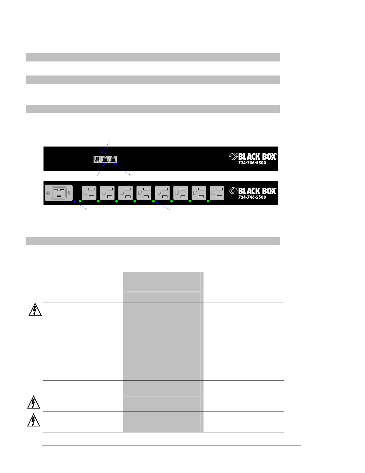
Equipment Overview
A number is printed above each outlet. These numbers may be used in commands that require an outlet
name. The power inlet connects to the electrical power source.
AUX SER NET
RJ45 Serial (RS-232) RJ45 Ethernet
RJ12 AUX
(For connection to optional Environmental Monitor)
4321 8765
AC Power Inlet Outlet Power Status LED
Figure 2.1 Enhanced PDU Product Views
Safety Precautions
This section contains important safety and regulatory information that should be reviewed before
installing and using the Power View product. For input and output current ratings, see Power Ratings
in Appendix C: Technical Specifications.
Only for installation and use in a
Service Access Location in accordance
with the following installation and use
instructions.
This equipment is designed to be
installed on a dedicated circuit.
Dedicated circuit must have circuit
breaker or fuse protection.
Power Views have been designed
without a master circuit breaker or fuse
to avoid becoming a single point of
failure. It is the customer’s
responsibility to provide adequate
protection for the dedicated power
circuit. Protection of capacity equal to
the current rating of the Power View
must be provided and must meet all
applicable codes and regulations. In
North American, protection must have a
10,000A interrupt capacity.
The plug on the power supply cord
shall be installed near the equipment
and shall be easily accessible.
Always disconnect the power supply
cord before opening to avoid electrical
shock.
WARNING! High leakage current!
Earth connection is essential before
connecting supply!
Destiné à l'installation et l'utilisation
dans le cadre de Service Access
Location selon les instructions
d'installation et d'utilisation.
Cet équipement est conçu à être
installé sur un circuit spécialisé.
Le circuit spécialisé doit avoir un
disjoncteur ou une protection de
fusible. Power Views ont été conçus
sans disjoncteur général ni fusible pour
éviter que cela devient un seul endroit
de panne. C’est la responsabilité du
client de fournir une protection
adéquate pour le circuit-alimentation
spécialisé. Protection de capacité
équivalant à la puissance de
l'équipement, et respectant tous les
codes et normes applicables. Les
disjoncteurs ou fusibles destinés à
l'installation en Amérique du Nord
doivent avoir une capacité
d'interruption de 10.000 A.
La prise sur le cordon d’alimentation
sera installée près de l’équipement et
sera facilement disponible.
Toujours déconnecter le cordon
d’alimentation avant d’ouvrir pour
éviter un choque électrique.
ATTENTION ! Haut fuite très
possible ! Une connection de masse
est essentielle avant de connecter
l’alimentation !
Nur für Installation und Gebrauch an
Anschlusszugriffspunkten gemäß der
folgenden Installations- und
Gebrauchsanweisungen.
Diese Ausrüstung ist zur Installation in
einem festen Stromkreis vorgesehen.
Der feste Stromkreis muss mit einem
Schutzschalter oder einem
Sicherungsschutz versehen sein.
Ein Power Views verfügt über keinen
Hauptschutzschalter bzw. über keine
Sicherung, damit kein einzelner
Fehlerpunkt entstehen kann. Der
Kunde ist dafür verantwortlich, den
Stromkreis sachgemäß zu schützen.
Der Kapazitätsschutz entspricht der
aktuellen Stromstärke der Geräte und
muss alle relevanten Codes und
Bestimmungen erfüllen. Für Installation
in Nordamerika müssen Ausschalter
bzw. Sicherung über 10.000 A
Unterbrechungskapazität verfügen.
Der Stecker des Netzkabels muss in
der Nähe der Ausrüstung installiert
werden und leicht zugänglich sein.
Ziehen Sie vor dem Öffnen immer das
Netzkabel heraus, um die Gefahr eines
elektrischen Schlags zu vermeiden.
ACHTUNG! Hoher Verluststrom! Ein
Erdungsanschluss ist vor dem
Einschalten der Stromzufuhr
erforderlich!
6 • Installation Power View Enhanced PDU
Installation and Operations Manual
Page 11

Mounting
1. Select the appropriate bracket mounting points for proper mounting depth within the rack.
2. Attach the brackets to these mounting points with two screws for each bracket.
3. Install the enclosure into your rack, using the slots in each bracket. The slots allow about ¼ inch
of horizontal adaptability to align with the mounting holes of your rack.
Connecting to the Power Source
Connect the female end of the power cord firmly into the connector, use a screwdriver to tighten the
screws on the retention bracket and plug the male end of the power cord into the AC power source.
Connecting Devices
To avoid the possibility of noise due to arcing:
1. Keep the device’s on/off switch in the off position until after it is properly attached to the outlets,
or
Log in to the Power View and turn the outlets off before connecting the devices to the unit(s).
2. Connect devices to the outlets.
Always disconnect the power supply cord before opening to avoid electrical shock.
Afin d’éviter les chocs électriques, débranchez le cable électrique avant d’ouvrir.
Immer Netzleitung auskuppeln vor den Aufmachen um elektrischen Schlag zu vermeiden.
Connecting to the Power View
Console (RS232) port
The Power View is equipped with an RJ45 Console RS-232 port for attachment to a PC or networked
terminal server. See Data Connections in Appendix C: Technical Specifications for more information
on the Console RS-232 port.
Ethernet port
The Power View is equipped with an RJ45 10/100Base-T Ethernet port for attachment to an existing
network. This connection allows access to the Power View via Telnet or HTML.
The Power View is configured with the following network defaults to allow unit configuration out-ofthe-box through either Telnet or HTML:
• IP address: 192.168.1.254
• Subnet Mask: 255.255.255.0
• Gateway: 192.168.1.1
The local PC network connection must be configured as noted below:
NOTE: Contact your system administrator for instructions in reconfiguring the network connection. Reconfiguration of
your network connection may require a restart to take effect.
• IP address: 192.168.1.x (where x is 2-253)
• Subnet Mask: 255.255.255.0
Power View Enhanced PDU Installation • 7
Installation and Operations Manual
Page 12

Page 13

Chapter 3: Operations
INTERFACES 10
Usernames and Passwords 10
HTML INTERFACE 10
Logging In 11
Outlet Control 11
Individual..............................................................................................................................11
Group....................................................................................................................................11
Environmental Monitoring 12
Input Feeds ...........................................................................................................................12
Configuration 12
System...................................................................................................................................12
Network ................................................................................................................................12
Telnet/HTTP .........................................................................................................................13
Outlets ..................................................................................................................................13
Groups ..................................................................................................................................13
Users.....................................................................................................................................14
FTP.......................................................................................................................................15
Tools 15
Restart ..................................................................................................................................15
COMMAND LINE INTERFACE 16
Logging In 16
Operations Commands 17
Outlet Control.......................................................................................................................17
Administration Commands 19
System Administration ..........................................................................................................19
TCP/IP Administration.........................................................................................................19
Telnet Administration Commands ........................................................................................20
HTTP Administration Commands.........................................................................................20
FTP Administration ..............................................................................................................21
Page 14

Operations
Interfaces
The Power View has two interfaces: the HTML interface accessed via the HTTP enabled Ethernet
connections and the command line for serial and Telnet connections.
Usernames and Passwords
The Power View has one predefined administrative user account (username/password: admn/admn) and
supports a maximum of 128 defined user accounts
NOTE: For security, Black Box recommends removal of the predefined administrative user account after a new account with
administrative rights has been created.
Only an administrative-level user may perform operations such as creating/removing user accounts and
command privileges, changing passwords and displaying outlet and user information. An administrator may
also view the status of and control power to all outlets.
The administrator may create additional user accounts and then grant these users the right to view the
status of and control power to specific outlets, groups and ports.
Usernames may contain from 1-16 characters and are not case sensitive; spaces are not allowed.
Passwords may contain up to 16 characters, and are case sensitive.
HTML Interface
The HTML interface is constructed of three major components: the System Location bar, the
User/Navigation bar and the Control Screen. The System Location bar displays the Power View’s
location and IP address as well as the current Control Screen title. The User/Navigation bar displays the
current user and privilege level and provides access to all HTML pages. And the Control Screen is used
to display current data and allow changes to outlet states or system configuration.
The following sections describe each interface section/page and their use.
User/Navigation System Location Control Screen
Figure 3.1 Example HTML page
10 • Operations Power View Enhanced PDU
Installation and Operations Manual
Page 15

Logging In
Logging in through HTML requires directing the HTML client to the configured IP address of the unit.
To log in by HTML:
1. In the login window, enter a valid username and password and press OK.
Outlet Control
The Outlet Control section offers access to the Individual and Group outlet control pages. From the
Individual and Group pages, the user can review and manipulate power control functions for all outlets
and groups assigned to the current user. Both pages include the outlets absolute and descriptive names,
the Outlet Status reported to the Power View by the outlet, the current Control State being applied by the
Power View and the outlet load in amperes.
Available outlet and group power states may be set to on, off or reboot; the reboot operation turns the
outlet(s) off, delays for a period of 15 seconds and then turns the outlet(s) on.
Outlet State/Control State Field Values
Outlet State Control State Description
On On Outlet is on
Off Off Outlet is off
Off Pend On Outlet is off and about to turn on in response to a sequence timer
Off Reboot Outlet is off and a Reboot action has been initiated
On Idle On A restart has occurred – Last Control State has been maintained
Off Idle Off A restart has occurred – Last Control State has been maintained
On Wake On A power-loss has occurred – Wakeup State has been applied
Off Wake Off A power-loss has occurred – Wakeup State has been applied
On/Wait Off Outlet state in transition – Requery of outlet status required
Off/Wait On Outlet state in transition – Requery of outlet status required
On/Error varies Error State – Outlet should be off but current is sensed at the outlet
Off/Error varies Error State – Outlet should be on but no current is sensed at the outlet
No Comm varies Communication to the outlet has been lost*
Individual
The Individual outlet control page displays all outlets assigned to the current user. The user may apply
on, off or reboot actions to individual, multiple or all accessible outlets.
If you enter an invalid username or password, you will be prompted again.
You are given three attempts to enter a valid username and password combination. If all three fail, the
session ends and a protected page will be displayed.
* Control State will be applied when communication is re-established
To apply actions to individual or multiple outlets:
In the Individual Outlet Control section, select the desired action from the Control Action drop-down
menu for each individual outlet to be changed and press Apply.
To apply an action to all outlets:
In the Global Control section, select the desired action from the Control Action drop-down menu and press
Apply.
Group
The Group outlet control page displays all groups assigned to the current user as well as the outlets for
each group.
To select a group:
Select the group name from the drop-down menu and press Select. The page will refresh to display all
outlets associated to the selected group name.
To apply an action to a group:
Select the desired action from the drop-down menu and press Apply.
Power View Enhanced PDU Operations • 11
Installation and Operations Manual
Page 16

Environmental Monitoring
The Environmental Monitoring section offers access to the Input Feed page. This section is available to
administrative level users and users with Environmental Monitoring view rights.
Input Feeds
The Input Load page displays the Power View’s absolute and descriptive name and the cumulative input
load in amperes of all devices attached to the Power View at the time the page was loaded. This page will
refresh automatically every 10 seconds.
Configuration
The Configuration section offers access to all unit configuration options including Network, HTTP,
Outlets, Groups, Users, and FTP. This section is available to administrative level users only.
System
The System configuration page is used for reference of system information such as Ethernet NIC Serial
Number, Ethernet MAC address and system firmware and hardware revisions as well as assignment and
maintenance of the system location and Power View descriptive names.
For description names, up to 24 alphanumeric and other typeable characters (ASCII 33 to 126 decimal –
spaces and colon characters are not allowed) are allowed.
NOTE: Spaces may be used for the location description only.
Creating a descriptive location name:
Click on the Tower Names link.
On the subsequent Tower Names page, enter a descriptive name and press Apply.
Creating a descriptive input feed name:
Click on the Input Feed Names link.
On the subsequent Input Feed Names page, enter a descriptive name and press Apply.
Creating a descriptive outlet name:
Click on the Outlet Names link which will open the Outlets configuration page. See Outlets on page 13
for additional information on creating descriptive outlet names.
Network
The Network configuration page is used for maintenance of the network interface. From this page an
administrator may configure the IP address, subnet mask and gateway address as well as view the link
status, speed and duplex value.
The Power View is configured with the following network defaults to allow unit configuration out-of-thebox through either Telnet or HTML:
• IP address: 192.168.1.254
• Subnet Mask: 255.255.255.0
• Gateway: 192.168.1.1
The initial local PC network connection must be configured as noted below:
NOTE: Contact your system administrator for instructions in reconfiguring the network connection. Reconfiguration of your
network connection may require a restart to take effect.
• IP address: 192.168.1.x (where x is 2-253)
• Subnet Mask: 255.255.255.0
NOTE: The unit must be restarted after network configuration changes. See Performing a warm boot: on page 15.
Setting the IP address, subnet mask or gateway:
In the appropriate field, enter the IP address, subnet mask or gateway address and press Apply.
12 • Operations Power View Enhanced PDU
Installation and Operations Manual
Page 17

Telnet/HTTP
The Telnet/HTTP configuration page used to enable or disable Telnet support, configure the port number
that the Telnet or HTTP server watches and responds to and selection of the method of authentication used.
Enabling or disabling Telnet support:
Select Enabled or Disabled from the Telnet Server drop-down menu and press Apply.
Changing the Telnet or HTTP server port number:
In the appropriate Port field, enter the port number and press Apply.
Setting the HTTP authentication method:fs
The Power View HTTP server supports two authentication methods for security and validation of the
username-password – Basic and MD5 digest.
The Basic method utilizes Base64 encoding to encode and deliver the username-password over the
network to the HTTP server for decoding and authentication. This basic method is supported by all web
browsers and offers a minimum level of security.
NOTE: The Base64 algorithm is widely-known and susceptible to packet-sniffer attack for acquisition of the encoded
username-password string.
The MD5 digest method provides stronger protection utilizing one-way encoded hash numbers, never
placing the username-password on the network. Instead, the sending browser creates a challenge code
based on the hash algorithm, provided username-password and unique items such as the device IP address
and timestamp, which is compared against the HTTP server internal user database of valid challenge
codes. The MD5 digest method offers a higher level of security than the Basic method but at present is
not supported by all browsers.
NOTE: MD5 is known to be fully supported by Internet Explorer 5.0+
Select Basic or MD5 from the Authentication drop-down menu and press Apply.
Outlets
The Outlets configuration page is used for assignment and/or editing of outlet descriptive names and wakeup states.
Editing the outlet descriptive name:
Click on the Edit link in the Action column next to the outlet to be configured.
On the subsequent Outlet Edit page, enter the descriptive name. Up to 24 alphanumeric and other typeable
characters (ASCII 33 to 126 decimal, spaces and colon characters are not allowed) are allowed. Press Apply.
Changing the outlet wakeup state:
Click on the Edit link in the Action column next to the outlet to be configured.
On the subsequent Outlet Edit page, select On or Off from the Wakeup State drop-down menu and press Apply.
Groups
The Groups configuration page is used for creation and deletion of group and assignment of outlets to groups.
Creating a group:
Enter a descriptive group name in the Group Name field. Up to 24 alphanumeric and other typeable characters
(ASCII 33 to 126 decimal, spaces and colon characters are not allowed) are allowed. Press Apply.
Removing a group:
Click on the Remove link in the Action column for the group to be removed and press Yes on the
subsequent confirmation window.
Adding and Deleting outlets from a group:
Press the Edit link in the Action column for the associated group.
On the subsequent Group Edit page, select or deselect outlets to be included in that group. Press Apply.
Power View Enhanced PDU Operations • 13
Installation and Operations Manual
Page 18

Users
The Users configuration page is used for creation and removal of usernames, assignment of accessible
outlets and group, assignment of privilege levels and the changing of user passwords.
Creating a new user:
Enter a user name in the Username field. Up to 24 alphanumeric and other typeable characters (ASCII 33
to 126 decimal, spaces and colon characters are not allowed) are allowed.
Enter a password for the new user and verify in the Password and Verify Password fields. For security,
password characters are not displayed. Press Apply.
Removing a user:
Click on the Remove link in the Action column for the user to be removed and press Yes on the
subsequent confirmation window.
Changing a user password:
Click on the Edit link in the Action column for the associated user.
On the subsequent User Edit page, enter a password and verify the new password for the new user in the
Password and Verify Password fields. For security, password characters are not displayed. Press Apply.
Changing a user’s access privilege level:
The Power View has two defined access privilege levels; Admin and User:
• Admin: Full-access for all configuration, control (On, Off, Reboot), status and Pass-Thru.
• User: Partial-access for control (On, Off, Reboot), status and Pass-Thru of assigned
outlets, groups and serial/Pass-Thru ports.
The administrator may also grant administrative privileges to other user accounts allowing the Power View to
have more than one administrative-level user.
NOTE: You cannot remove administrative privileges from the Admn user unless another user has already been given
administrative access level privileges created.
Click on the Edit link in the Action column for the associated user.
On the subsequent User Edit page, select Admin, User, On-only or View-only from the Access Level
drop-down menu and press Apply.
Granting or removing Environmental Monitoring viewing privileges:
Click on the Edit link in the Action column for the associated user.
On the subsequent User Edit page, select Yes or No from the Environmental Monitoring drop-down menu
and press Apply.
NOTE: This also grants or removes viewing privileges for the optional Power View Environmental Manager. See the Power
View Environmental Manager Installation and Operations manual for more information.
Adding and Deleting outlet access:
Click on the Outlets link in the Access column for the associated user.
On the subsequent User Outlets page, select or deselect outlets to be accessed by the user and press Apply.
Adding and Deleting group access:
Click on the Groups link in the Access column for the associated user.
On the subsequent User Groups page, select or deselect group to be accessed by the user and press Apply.
14 • Operations Power View Enhanced PDU
Installation and Operations Manual
Page 19

FTP
The FTP configuration page is used for setup and maintenance of all settings required to perform an FTP
firmware upload. See Appendix B: Uploading Firmware for more information on uploading firmware.
Setting the FTP Host IP Address:
Enter the IP address in the Host IP Address field and press Apply.
Setting the FTP username:
Enter the FTP server username in the Username field, and press Apply.
Setting the FTP password:
Enter the FTP server password in the Password field, and press Apply.
Setting the filepath:
Enter the path of the file to be uploaded in the Directory field, and press Apply.
Setting the filename for upload:
Enter the filename of the file to be uploaded in the Filename field, and press Apply.
Testing the FTP upload configuration:
This test validates that the unit is able to contact and log onto the specified FTP server, download the
firmware file and verify that the firmware file is valid for this unit.
Press Test.
Tools
The Tools section contains access to rebooting the unit, uploading new firmware as well as resetting the unit to
factory defaults. This section is available to administrative level users only.
Restart
Performing a warm boot:
Select the Restart from the Action drop-down menu and press Apply.
Note: System user/outlet/group configuration or outlet states are NOT changed or reset with this command.
Resetting to factory defaults:
See Appendix A: Resetting to Factory Defaults for more information on resetting an Power View to factory
defaults from the HTML interface.
Uploading new firmware:
See Appendix B: Uploading Firmware for more information on uploading new firmware from the HTML
interface.
Power View Enhanced PDU Operations • 15
Installation and Operations Manual
Page 20

Command Line Interface
Logging In
Logging in through Telnet requires directing the Telnet client to the configured IP address of the unit.
Logging in through the Console (RS232) port requires the use of a terminal or terminal emulation
software configured to support ANSI or VT100 and a supported data rate (300, 1200, 2400, 4800, 9600,
19200, 38400, 57600, or 115200 BPS) - 8 data bits-no parity-one stop bit and Device Ready output signal
(DTR or DSR).
To log in by RS-232 or Telnet:
1. Press Enter. The following appears, where x.xx is the firmware version:
Power View Enhanced PDU Version x.xx
Username:
NOTE: Logging in by Telnet will automatically open a session. It is not necessary to press Enter.
2. At the Username: and Password: prompts, enter a valid username and password. And press Enter.
You are given three attempts to enter a valid username and password combination. If all three fail,
the session ends.
You may enter commands in any combination of uppercase and lowercase. You must enter all command
characters correctly; there are no command abbreviations. There are two types of commands: operations
and administration. A user must have administrative privileges to use the administration commands. The
following tables list and briefly describe each command.
Operations Command Summary
Command Description
On Turns one or more outlets on
Off Turns one or more outlets off
Reboot Reboots one or more outlets
Status Displays the on/off status of one or more outlets
Login Ends the current session and brings up the Username: prompt
Logout Ends a session
Quit Ends a session
Administrative Command Summary
Restart Performs a warm boot
Set FTP Filename Specifies the file to be uploaded via FTP
Set FTP Filepath Specifies the filepath for the file to be uploaded
Set FTP Host Sets the FTP Host IP address
Set FTP Password Sets the password for the FTP Host
Set FTP Username Sets the username for the FTP Host
Set Gateway Sets the Gateway
Set HTTP Port Sets the HTTP server port number
Set HTTP Security Sets the HTTP server authentication method
Set Ipaddress Sets the Power View Enhanced PDU IP address
Set Subnet Mask Sets the Subnet Mask
Set Telnet Port Sets the Telnet server port number
Set Telnet Enables or disables Telnet access
Show FTP Displays FTP configuration information
Show Network Display network configuration information
Version Displays the Power View Enhanced PDU firmware version
16 • Operations Power View Enhanced PDU
Installation and Operations Manual
Page 21

Operations Commands
Operations commands manage outlet states, provide information about the Power View environment and
control session operations.
NOTE: Users must be granted access to affect any change in outlet state.
Outlet Control
Turning outlets on
The On command turns on one or more outlets. When the command completes, a display indicating all
outlets affected and their current states will be displayed.
To turn outlets on:
At the Power View Enhanced PDU: prompt, type on, followed by an outlet name, and press Enter, or
Type on, followed by a group name, and press Enter, or
Type on all and press Enter.
Examples
The following command turns the second outlet on, using the outlet ’s absolute name:
Power View Enhanced PDU: on .aa2<Enter>
The following command turns on all the outlets in the group named ServerGroup_1:
Power View Enhanced PDU: on ServerGroup_1<Enter>
Turning outlets off
The Off command turns off one or more outlets. When the command completes, a display indicating all
outlets affected and their current states will be displayed.
To turn outlets off:
At the Power View Enhanced PDU: prompt, type off, followed by an outlet name, and press Enter, or
Type off, followed by a group name, and press Enter, or
Type off all and press Enter
Examples
The following command turns off the outlet named FileServer_1:
Power View Enhanced PDU: off FileServer_1<Enter>
The following command turns off all outlets:
Power View Enhanced PDU: off all<Enter>
Rebooting outlets
The Reboot command reboots one or more outlets. This operation turns the outlet(s) off, delays for a
period of 15 seconds and then turns the outlet(s) on. When the command completes, a display indicating
all outlets affected and their current states will be displayed.
NOTE: It is necessary to reissue the Status command to verify that the outlets have rebooted after 15 seconds. See Displaying
outlet status for more information.
To reboot one or more outlets:
At the Power View Enhanced PDU: prompt, type reboot, followed by an outlet name, and press Enter, or
Type reboot, followed by a group name, and press Enter, or
Type reboot all and press Enter.
Example
The following command reboots all the outlets in the group named ServerGroup_1:
Power View Enhanced PDU: reboot ServerGroup_1<Enter>
Power View Enhanced PDU Operations • 17
Installation and Operations Manual
Page 22

Displaying outlet status
The Status command displays the on/off status of one or more outlets. The command displays the status
of only those outlets for which the current username has power control access.
This display includes the outlet absolute and descriptive names, the Outlet State reported to the Sentry by
the outlet and the current Control State being applied by the Sentry. If you do not specify any parameter
with this command, the status of all accessible outlets is displayed.
For more information on outlet and control state values, see Outlet Control on page 11.
To display on/off status of one or more outlets:
At the Power View Enhanced PDU: prompt, type status, followed by an outlet name, and press Enter, or
Type status, followed by a group name, and press Enter, or
Type status and press Enter.
Examples
The following command displays the on/off status of the outlet named FileServer_1:
Power View Enhanced PDU: status FileServer_1<Enter>
Outlet Outlet Outlet Control
ID Name Status State
.AA3 FileServer_1 On On
The following command displays the on/off status of all accessible outlets:
Power View Enhanced PDU: status<Enter>
Outlet Outlet Outlet Control Outlet
ID Name Status State Load
.AA1 DataServer_1 On On 5.0 Amps
.AA2 WebServer_1 On On 2.5 Amps
.AB1 FileServer_1 On On 9.5 Amps
.AB2 On On 0.0 Amps
The following command displays the on/off status for outlets in the group ServerGroup_1:
Power View Enhanced PDU: status ServerGroup_1<Enter>
Group: ServerGroup_1
Outlet Outlet Outlet Control Outlet
ID Name Status State Load
.AA1 DataServer_1 On On 5.0 Amps
.AA2 WebServer_1 On On 2.5 Amps
.AB1 FileServer_1 On On 9.5 Amps
Starting a new session
The Login command activates the Username: prompt. The current session ends, allowing a user to log in
and start a new session under a different username.
To start a new session:
At the Power View Enhanced PDU: prompt, type login and press Enter. The Username: prompt appears.
Ending a session
The Quit or Logout commands ends a session. A session ends automatically when no activity is detected
for five minutes, or upon loss of connection.
To end a session:
At the Power View Enhanced PDU: prompt, type quit and press Enter, or
Type logout and press Enter.
18 • Operations Power View Enhanced PDU
Installation and Operations Manual
Page 23

Administration Commands
System Administration
Displaying the Power View Enhanced PDU firmware version
The Version command displays the firmware version.
To display the firmware version:
At the Power View Enhanced PDU: prompt, type version and press Enter.
Performing a warm boot
The Restart command performs a warm boot.
NOTE: System user/outlet/group configuration or outlet states are NOT changed or reset with this command.
To perform a warm boot:
At the Power View Enhanced PDU: prompt, type restart and press Enter.
TCP/IP Administration
NOTE: A restart is required after setting or changing ANY TCP/IP configurations. See Performing a warm boot on page 19
for more information.
Setting the IP address
The Set Ipaddress command sets the TCP/IP address of the network interface controller.
To set the IP address:
At the Power View Enhanced PDU: prompt, type set ipaddress, followed by the IP address and press Enter.
Example
The following command sets the IP address to 12.34.56.78:
Power View Enhanced PDU: set ipaddress 12.34.56.78<Enter>
Setting the subnet mask
The Set Subnet command sets the subnet mask for the network the Power View Enhanced PDU will be
attached to.
To set the subnet mask:
At the Power View Enhanced PDU: prompt, type set subnet, followed by the subnet mask and press
Enter.
Example
The following command sets the subnet mask to 255.0.0.0
Power View Enhanced PDU: set subnet 255.0.0.0<Enter>
Setting the gateway
The Set Gateway command sets the IP address of the default gateway the Power View Enhanced PDU
uses to access external networks.
To set the gateway IP address:
At the Power View Enhanced PDU: prompt, type set gateway, followed by the gateway IP address and press
Enter.
Example
The following command set the gateway IP address to 12.34.56.1:
Power View Enhanced PDU: set gateway 12.34.56.1<Enter>
Power View Enhanced PDU Operations • 19
Installation and Operations Manual
Page 24

Telnet Administration Commands
Enabling and disabling Telnet support
The Set Telnet command is used to enable or disable Telnet support.
To enable or disable Telnet support:
At the Power View Enhanced PDU: prompt, type set telnet, followed by enabled or disabled and press Enter.
Changing the Telnet port
With Telnet support enabled, the Telnet server watches and responds to requests on the default Telnet port
number 23. This port number may be changed using the Set Telnet Port command.
To change the Telnet socket:
At the Power View Enhanced PDU: prompt, type set telnet port, followed by the port number and press Enter.
Example
The following changes the Telnet port number to 7001:
Power View Enhanced PDU: set telnet port 7001<Enter>
HTTP Administration Commands
Changing the HTTP server port
With HTTP support enabled, the HTTP server watches and responds to requests on the default HTTP port
number 80. This port number may be changed using the Set HTTP Port command.
To change the HTTP port:
At the Power View Enhanced PDU: prompt, type set http port, followed by the port number and press Enter.
Example
The following changes the HTTP port number to 2048:
Power View Enhanced PDU: set HTTP port 2048<Enter>
Setting the HTTP authentication method
The Set HTTP Security command is used to set the method of authentication. The Power View Enhanced
PDU HTTP server supports two authentication methods for security and validation of the usernamepassword – Basic and MD5 digest.
For more information on authentication methods, see Changing the Telnet or HTTP server port number:
In the appropriate Port field, enter the port number and press Apply.
Setting the HTTP authentication method: on page 13.
To set the HTTP authentication method:
At the Power View Enhanced PDU: prompt, type set http security, followed by basic or md5 and press Enter.
20 • Operations Power View Enhanced PDU
Installation and Operations Manual
Page 25

Displaying network configuration information
The Show Network command displays TCP/IP and Web configuration information.
• NIC module serial number, MAC address and hardware revision code
• IP address, subnet mask and gateway
• Enabled-disabled status of Telnet support
• Telnet and HTTP port numbers
• HTTP authentication method
• Network link status, connection speed and duplex value
To display network configuration information:
At the Power View Enhanced PDU: prompt, type show network and press Enter.
Example
The following command displays the network configuration information:
Power View Enhanced PDU: show network<Enter>
Network Configuration
NIC S/N : 1600001
MAC Address: 00-0a-9c-10-00-01
H/W Rev Code: 0
IP Address: 12.34.56.78
Subnet Mask: 255.0.0.0
Gateway: 12.34.56.1
Telnet: Enabled Port: 23
HTTP Port: 80 Security: Basic
Network Status
Link: Up
Speed: 100 Mbps
Duplex: Half
FTP Administration
The following commands are used to configure the Power View Enhanced PDU for an FTP firmware
upload. See Appendix B: Uploading Firmware for more information on initiating a FTP firmware upload.
Setting the FTP Host IP address
The Set FTP Host command sets the FTP host IP address allowing for firmware file uploads.
To set the FTP Host IP address:
At the Power View Enhanced PDU: prompt, type set ftp host, followed by the Host IP address and press
Enter.
Example
The following command sets the FTP Host IP address to 12.34.56.99:
Power View Enhanced PDU: set ftp host 12.34.56.99<Enter>
Setting the FTP username
The FTP Username command sets the username as required by the FTP Host.
To set the FTP username:
At the Power View Enhanced PDU: prompt, type set ftp username, followed by the FTP username and
press Enter.
Example
The following command sets the FTP username to Guest:
Power View Enhanced PDU: set ftp username guest<Enter>
Power View Enhanced PDU Operations • 21
Installation and Operations Manual
Page 26

Setting the FTP Password
The FTP Password command sets the password as required by the FTP Host.
To set the FTP password:
At the Power View Enhanced PDU: prompt, type set ftp password, followed by the FTP password and
press Enter.
Example
The following command sets the FTP password to OpenSesame:
Power View Enhanced PDU: set ftp password OpenSesame<Enter>
Setting the filename to be uploaded
The FTP Filename command sets the filename of the firmware file to be uploaded.
To set the FTP filename:
At the Power View Enhanced PDU: prompt, type set ftp filename, followed by the firmware filename
and press Enter.
Example
The following command sets the FTP filename to pv-v51a.bin:
Power View Enhanced PDU: set ftp filename pv-v51a.bin<Enter>
Setting the filepath for the file to be uploaded
The FTP Filepath command sets the filepath for the firmware file to be uploaded.
To set the FTP filepath:
At the Power View Enhanced PDU: prompt, type set ftp filepath, followed by the filepath and press Enter.
Example
The following command sets the FTP filepath to ftp://Powerview:
Power View Enhanced PDU: set ftp filepath ftp://Powerview<Enter>
Displaying FTP configuration information
The Show FTP command displays all FTP configuration information.
• FTP Host IP address
• FTP Host username and password
• Firmware filepath and filename
To display FTP configuration information:
At the Power View Enhanced PDU: prompt, type show ftp and press Enter.
Example
The following command displays the FTP configuration information:
Power View Enhanced PDU: show ftp<Enter>
FTP Configuration
Host IP Address: 12.34.56.99
Username: guest
Password: OpenSesame
Directory: ftp://powerview
Filename: pv-v51a.bin
22 • Operations Power View Enhanced PDU
Installation and Operations Manual
Page 27

Chapter 4: Appendices
APPENDIX A: RESETTING TO FACTORY DEFAULTS 24
To reset to factory defaults from the HTML interface ...................................................................24
To reset the to factory defaults from the command line.................................................................24
To reset to factory defaults using the reset button..........................................................................24
PPENDIX B: UPLOADING FIRMWARE 24
A
To initiate an FTP upload session ..................................................................................................24
To initiate an FTP upload session from the command line ............................................................24
A
PPENDIX C: TECHNICAL SPECIFICATIONS 25
Models............................................................................................................................................25
Power Ratings ................................................................................................................................25
Physical Specifications...................................................................................................................25
Data Connections ...........................................................................................................................25
LED Indicators ...............................................................................................................................25
A
PPENDIX D: PRODUCT REGISTRATION AND SUPPORT 26
Technical Support ..........................................................................................................................26
Troubleshooting .............................................................................................................................26
Page 28

Appendices
Appendix A: Resetting to Factory Defaults
You may reset the non-volatile RAM that stores all configurable options. This clears all administratoreditable fields and resets all command line configurable options to their default values, including all
user accounts.
You may reset the unit to factory defaults from the HTML interface, the command line or by pressing
the reset button. You must have administrator-level privileges to issue the command. Using the reset
button may be necessary when a forgotten password prevents administrator login. Each of the methods
update the current working configuration to the factory defaults.
NOTE: Resetting the unit to factory defaults resets all TCP/IP and Web configurations. Reconfiguring of the TCP/IP and
Web settings will be required.
To reset to factory defaults from the HTML interface
On the Restart page in the Tools section of the HTML interface, select Restart and reset to factory
defaults from the drop-down menu and press Apply.
To reset the to factory defaults from the command line
At the Power View Enhanced PDU: prompt, type restart factory and press Enter.
To reset to factory defaults using the reset button
Press and hold the reset button between ten and fifteen seconds.
NOTE: If the reset button is depressed and held for more than 15 seconds, the reset will abort.
Appendix B: Uploading Firmware
You may upload new versions of firmware using File Transfer Protocol (FTP). This allows access to new
firmware releases for firmware improvements and new features additions.
NOTE: To begin an FTP upload session, you must first configure the FTP Host address, username/password, filename and
filepath. For information on configuring the FTP settings required for firmware upload see Chapter 3: Operations.
You may initiate an FTP upload session from the HTML interface or the command line. You must
have administrator-level privileges to initiate an upload.
To initiate an FTP upload session
On the Restart page in the Tools section of the HTML interface, select Restart and upload firmware
via FTP from the drop-down menu and press Apply.
Upon issuing this command the unit will restart and upload the firmware file specified with the FTP
Filename command from the previously configured FTP Host. See FTP Administration in Chapter 3:
for more information.
To initiate an FTP upload session from the command line
The Restart FTPLoad command initiates an upload of firmware. Upon issuing this command the Power
View will restart and upload the firmware file specified with the FTP Filename command from the
previously configured FTP Host. See FTP Administration in Chapter 3: for more information.
To initiate an FTP firmware upload session:
At the Power View Enhanced PDU: prompt, type restart ftpload and press Enter.
24 • Appendices Power View Enhanced PDU
Resetting to Factory Defaults Installation and Operations Manual
Page 29

V
t
l
g
Appendix C: Technical Specifications
Models
Standard Models
Model Voltage Inlet Outlets
PS570A 100-120V AC, 50/60 Hz IEC 60320 C19 8x NEMA 5-15
Power Ratings
Input Current Ratings
L’indice du courant d’entrée L’indice du courant de sortie
Eingangsstromstärke Ausgangsstromstärke
Model
Modele Tension Courran
Modell Spannun
PS570A 100-120V 50/60Hz 20 10 15 20 20
1
All current ratings are in amperes.
Tous les indices de courant sont en ampères.
Alle Angaben der Stromstärke erfolgen in Ampere.
2
1-4, 5-8
3
1-8
Physical Specifications
Model
Physical
Temperature Operating
Elevation Operating
(above MSL)
Relative Humidity Operating
Approvals
oltage Current Outlet
(H x W x D)
Size
Weight
Storage
Storage
Storage
1
Strom Anschlussstelle Insgesamt
1
cCSAus - UL 1950, CAN/CSA 22.2 No. 950-95
TUV-GS - EN60950:2000
Prise Tota
Output Current Ratings
Quad
2
PS570A
3.5 x 17.0 x 17.0 in.
22.8 lbs
0° to 50° C (32° to 122° F)
-40° to 85° C (-40° to 185° F)
0 to 10,000 ft (0 to 3000 m)
0 to 50,000 ft (0 to 15 000 m)
10 to 90%, non-condensing
10 to 90%, non-condensing
cCSAus, TUV-GS
1
Octet
3
Total
Data Connections
RS-232 port
Enhanced PDUs are equipped standard with an RJ45 DTE RS-232c serial port. This connector may be
used for direct local access or from other serial devices such as a terminal server. An RJ45 crossover
cable is provided for connection to an RJ45 DCE serial port.
Pin DTE Signal Name Input/Output
1 Request to Send RTS Output
2 Data Terminal Ready DTR Output
3 Transmit Data TD Output
4 Signal Ground
5 Signal Ground
6 Receive Data RD Input
7 Data Set Ready DSR Input
8 Clear to Send CTS Input
LED Indicators
Enhanced PDUs are equipped with a status LED for each outlet. A lit/on LED indicates that power is
being supplied to the outlet and a darkened/off LED indicates that there is no power at the outlet.
67543218
Power View Enhanced PDU Appendices • 25
Installation and Operations Manual Technical Specifications
Page 30

Appendix D: Product Registration and Support
Technical Support
Black Box understands that there are often questions when installing and/or using a new product.
FREE Technical Support is provided 24 hours a day, 7 days a week.
Black Box Corporation
1000 Park Drive Tel: 724.746.5500 Web: www.blackbox.com
Lawrence, PA 15055 USA Fax: 724.746.0746 Email: info@blackbox.com
Troubleshooting
Calling BLACK BOX
If you determine that your Power View is malfunctioning, do not attempt to alter or repair the unit. It
contains no user-serviceable parts. Contact Black Box Technical Support at 724-746-5500.
Before you do, make a record of the history of the problem. We will be able to provide more efficient
and accurate assistance if you have a complete description, including:
• The model and serial number of the problem unit.
• The nature and duration of the problem.
• When the problem occurs.
• Any particular application that, when used, appears to create the problem or make it worse.
Shipping and Packaging
If you need to transport or ship your Power View:
• Package it carefully. We recommend that you use the original container.
• If you are returning the unit, make sure you include everything you received with it. Before
you ship for return or repair, contact Black Box to get a Return Materials Authorization
(RMA) number.
26 • Appendices Power View Enhanced PDU
Product Registration and Support Installation and Operations Manual
Page 31

Page 32

Black Box Corporation order
1000 Park Drive technical support tel +1.724.46.5500
Lawrence, PA 15055 fax +1.724.746.0746
USA
www.blackbox.com
info@backbox.com
301-0401-2 Rev. A (013104) - © Black Box Corporation. All rights reserved.
toll free +1.877.877.BBOX
 Loading...