

Page 1

1000 Park Drive • Lawrence, PA 15055-1018 • 724-746-5500 • Fax 724-746-0746
© Copyright 1998. Black Box Corporation. All rights reserved.
Page 2
CUSTOMER
SUPPORT
INFORMATION
AUGUST 1995
SD015A
Programmable Security Guard
Order toll-free in the U.S. 24 hours, 7 A.M. Monday to midnight Friday: 877-877-BBOX
FREE technical support, 24 hours a day, 7 days a week: Call 724-746-5500 or fax 724-746-0746
Mail order: Black Box Corporation, 1000 Park Drive, Lawrence, PA 15055-1018
Web site: www.blackbox.com • E-mail: info@blackbox.com
PROGRAMMABLE
SECURITY GUARD
TXA RXA TXB RXB PWR
RESET
Page 3

PROGRAMMABLE SECURITY GUARD
1
FEDERAL COMMUNICATIONS COMMISSION
AND
INDUSTRY CANADA
RADIO FREQUENCY INTERFERENCE STATEMENTS
This equipment generates, uses, and can radiate radio frequency energy and if not installed and used properly, that is,
in strict accordance with the manufacturer’s instructions, may cause interference to radio communication. It has been
tested and found to comply with the limits for a Class A computing device in accordance with the specifications in
Subpart J of Part 15 of FCC rules, which are designed to provide reasonable protection against such interference when
the equipment is operated in a commercial environment. Operation of this equipment in a residential area is likely to
cause interference, in which case the user at his own expense will be required to take whatever measures may be
necessary to correct the interference.
Changes or modifications not expressly approved by the party responsible for compliance could void the user’s
authority to operate the equipment.
This digital apparatus does not exceed the Class A limits for radio noise emission from digital apparatus set out in the Radio
Interference Regulation of Industry Canada.
Le présent appareil numérique n’émet pas de bruits radioélectriques dépassant les limites applicables aux appareils numériques de
classe A prescrites dans le Règlement sur le brouillage radioélectrique publié par Industrie Canada.
INSTRUCCIONES DE SEGURIDAD (Normas Oficiales Mexicanas Electrical Safety Statement)
1. Todas las instrucciones de seguridad y operación
deberán ser leídas antes de que el aparato eléctrico
sea operado.
2. Las instrucciones de seguridad y operación deberán
ser guardadas para referencia futura.
3. Todas las advertencias en el aparato eléctrico y en
sus instrucciones de operación deben ser respetadas.
4. Todas las instrucciones de operación y uso deben ser
seguidas.
5. El aparato eléctrico no deberá ser usado cerca del
agua—por ejemplo, cerca de la tina de baño, lavabo,
sótano mojado o cerca de una alberca, etc..
6. El aparato eléctrico debe ser usado únicamente con
carritos o pedestales que sean recomendados por el
fabricante.
7. El aparato eléctrico debe ser montado a la pared o al
techo sólo como sea recomendado por el fabricante.
8. Servicio—El usuario no debe intentar dar servicio al
equipo eléctrico más allá a lo descrito en las
instrucciones de operación. Todo otro servicio
deberá ser referido a personal de servicio calificado.
9. El aparato eléctrico debe ser situado de tal manera
que su posición no interfiera su uso. La colocación
del aparato eléctrico sobre una cama, sofá, alfombra
o superficie similar puede bloquea la ventilación, no
se debe colocar en libreros o gabinetes que impidan
el flujo de aire por los orificios de ventilación.
10. El equipo eléctrico deber ser situado fuera del
alcance de fuentes de calor como radiadores,
registros de calor, estufas u otros aparatos
(incluyendo amplificadores) que producen calor.
11. El aparato eléctrico deberá ser connectado a
una fuente de poder sólo del tipo descrito en
el instructivo de operación, o como se indique
en el aparato.
12. Precaución debe ser tomada de tal manera que la
tierra fisica y la polarización del equipo no sea
eliminada.
13. Los cables de la fuente de poder deben ser guiados
de tal manera que no sean pisados ni pellizcados por
objetos colocados sobre o contra ellos, poniendo
particular atención a los contactos y receptáculos
donde salen del aparato.
14. El equipo eléctrico debe ser limpiado únicamente
de acuerdo a las recomendaciones del fabricante.
15. En caso de existir, una antena externa deberá ser
localizada lejos de las lineas de energia.
16. El cable de corriente deberá ser desconectado del
cuando el equipo no sea usado por un largo periodo
de tiempo.
17. Cuidado debe ser tomado de tal manera que
objectos liquidos no sean derramados sobre la
cubierta u orificios de ventilación.
18. Servicio por personal calificado deberá ser provisto
cuando:
A: El cable de poder o el contacto ha sido dañado;
u
B: Objectos han caído o líquido ha sido derramado
dentro del aparato; o
C: El aparato ha sido expuesto a la lluvia; o
D: El aparato parece no operar normalmente o
muestra un cambio en su desempeño; o
E: El aparato ha sido tirado o su cubierta ha sido
dañada.
Page 4

PROGRAMMABLE SECURITY GUARD
2
Contents
Chapter Page
1. Specifications .................................................................................................................................. 4
2. Introduction.................................................................................................................................... 5
2.1 Main Security Barriers........................................................................................................... 5
2.2 Features .................................................................................................................................. 5
2.3 Front-Panel Indicators........................................................................................................... 6
2.4 Reset Button........................................................................................................................... 6
3. Installation....................................................................................................................................... 7
3.1 Setting Internal DIP Switches for Individual Port Configurations..................................... 7
3.2 Connecting Devices to the Ports...........................................................................................14
3.3 Setting Up Modem Options..................................................................................................14
4. Operation ........................................................................................................................................15
4.1 Security Mode ........................................................................................................................15
4.1.1 How to Enter Security Mode.......................................................................................15
4.1.2 How to Exit Security Mode .........................................................................................15
4.1.3 How the PSG Reenters Security Mode .......................................................................15
4.1.4 Password Validation.....................................................................................................15
4.1.5 Callback After Password Validation............................................................................15
4.1.6 Secondary Password Validation ..................................................................................16
4.1.7 Entering or Reentering Security Mode......................................................................16
4.2 Pass-Thru Mode .....................................................................................................................16
4.2.1 How to Enter Pass-Thru Mode....................................................................................16
4.2.2 How to Exit Pass-Thru Mode ......................................................................................16
4.3 Program Mode.......................................................................................................................16
4.3.1 How to Enter Program Mode .....................................................................................17
4.3.2 How to Exit Program Mode ........................................................................................17
4.3.3 Step-by-Step Procedure ...............................................................................................17
4.3.4 Program Mode Options ..............................................................................................22
4.3.5 Add, Delete, List, and Edit Menu Options.................................................................22
4.3.6 Setting the Clock .........................................................................................................22
4.3.7 List-All Menu Option...................................................................................................22
4.4 RS-232 Control Leads Supported .........................................................................................24
4.5 Modem Control Procedures and Timing Requirements....................................................24
4.5.1 Answering an Incoming Call.......................................................................................24
4.5.2 Disconnecting at a Remote Modem ...........................................................................24
4.5.3 Disconnecting a Call from the Local Modem............................................................24
4.5.4 Making a Callback .......................................................................................................25
4.5.5 Ignoring an Incoming Call During a Callback Sequence.........................................25
4.6 Lead Operation If a Port is Configured for Modem Control.............................................25
4.6.1 Outputs.........................................................................................................................26
4.6.2 Inputs............................................................................................................................27
4.7 Sample Modem Configuration .............................................................................................27
Page 5

PROGRAMMABLE SECURITY GUARD
3
Contents (continued)
Chapter Page
4.8 Security Considerations................................................................................................................29
Figures
3-1. Internal Switch Locations for the PSG ....................................................................................... 7
4-1. The Program Mode Menu...........................................................................................................17
4-2. The LIST-ALL Option of the Main Programming Menu..........................................................23
Tables
3-1. Switch S1 (Port A: Options) ....................................................................................................... 8
3-2. Switch S2 (Port B: Options) ....................................................................................................... 9
3-3. Switch S3 (Port A: Baud Rate) ...................................................................................................10
3-4. Switch S4 (Port B: Baud Rate) ...................................................................................................11
3-5. Switch S5 (System Options) ........................................................................................................12
3-6. Switch S7 (Lead Options) ...........................................................................................................13
3-7. Jumper Settings............................................................................................................................14
4-1. RS-232 Control Leads Supported ...............................................................................................24
4-2. Output Leads with Modem Controls Enabled...........................................................................26
4-3. Input Leads with Modem Controls Enabled..............................................................................27
Page 6

PROGRAMMABLE SECURITY GUARD
4
Pins Supported — 1-8, 20, and 22
Data Rates — 45.5 to 38,400 bps (each port
individually selectable)
Memory — 1K buffer
Indicators — RXD and TXD for each port; Power
Enclosure — High-impact plastic
Interface — Asynchronous RS-232-C/V.24
Connectors — (2) DB9S 9-pin sub-D female
Power — Wallmount transformer
Size — 1.8”H x 5.5”W x 8.5”D
(4.6 x 14.0 x 21.6 cm)
Weight — 2 lb. (0.9 kg)
1. Specifications
Page 7

CHAPTER 2: Introduction
5
The Programmable Security Guard (PSG) adds
security to any RS-232 asynchronous port, to help
protect your computer resources from unauthorized
accesses. The PSG is an in-line buffer box with three
modes of operation:
• Security Mode
• Pass-Thru Mode
• Program Mode
After a reset, the unit is in “Security Mode.” While
in Security Mode the unit acts as an open switch,
and will not pass any data until certain security
barriers are broken. Once valid users successfully
pass through the security barriers, the unit will
change its mode to “Pass-Thru.” In Pass-Thru Mode
the unit buffers data received from each port and
retransmits this data out the other port, using the
configured word structure, data rate, and flow
control of that port. Program Mode is used to enter
and update passwords and other parameters for the
security barriers.
2.1 Main Security Barriers
• Primary password validation
• User’s location validation (“callback”)
• Secondary password validation
2.2 Features
• Configurable by the user via software
(program mode) and DIP-switch selection.
• 1K of memory available for buffering.
• Each port can be individually configured, via
DIP switches, for word structure (7 or 8 data
bits, even/odd/no parity), data rate (45.5 to
38.4 Kbps), and flow control (X-ON/X-OFF
or DTR/CTS).
• Battery-backed-up memory saves all programmed
information automatically in case the power fails.
• Program mode for entering primary passwords
and their associated parameters.
• Primary passwords can be assigned to either or
both ports of the PSG, for security protection in
any direction.
• DIP-switch-selectable password retry count
(1, 2, 3, or infinite).
• DIP-switch-selectable maximum time period for
entering primary and secondary passwords (10
seconds, 30 seconds, 1 minute, 2 minutes).
• Internal memory storage of up to 64 different
primary passwords, associated response strings,
and secondary passwords.
• User-programmed primary and secondary
passwords: up to 32 characters long.
• Optional status messages like:
“invalid password”
“primary password accepted, unit now in pass-
thru mode”
“primary password accepted, prepare for user
location validation”
“primary password accepted, enter secondary
password”
“secondary password accepted, unit now in
pass-thru mode”
NOTE: These messages can be disabled via DIP
switch on an individual-port basis for
additional security.
• Optional response string programmable for
every primary password defined by the user.
User-programmed response strings can be up
to 32 characters in length.
• Onboard clock so that the user can program
certain passwords as valid only during specific
times of the day (for example, night; evening).
2. Introduction
Page 8

PROGRAMMABLE SECURITY GUARD
6
2.3 Front-Panel Indicators
There are 5 LEDs on the unit’s right front panel.
• Power LED: Lights when power is present.
• RXDA: Flashes when Port A is receiving data.
• TXDA: Flashes when Port A is transmitting data.
• RXDB: Flashes when Port B is receiving data.
• TXDB: Flashes when Port B is transmitting data.
2.4 Reset Button
The location of the reset button is shown in Fig. 3-1.
Any time you make changes to the internal switch
settings, you must press the reset button to activate
the changes. While the PSG is resetting, it cannot
process data.
NOTE: Disconnecting power from the PSG will also
reset the unit.
Page 9
CHAPTER 3: Installation
77
Installing the PSG involves the following steps:
1. Setting the internal DIP switches for individual
port configurations.
2. Connecting devices to the ports.
3. Supplying power.
3.1 Setting Internal DIP Switches for Individual
Port Configurations
Remove the unit’s cover to expose the PC board.
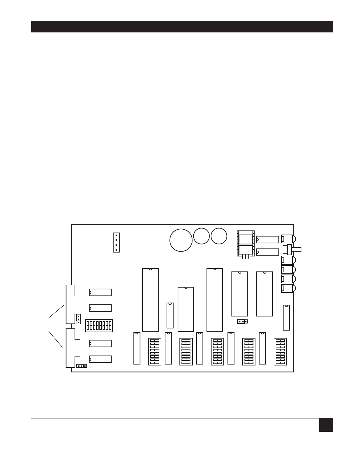
Figure 3-1 shows the internal switch locations.
IMPORTANT
The internal DIP switches on your PSG
may be labeled either OPEN and
CLOSED or ON and OFF. For all internal
DIP switches in the PSG, OPEN=OFF
and CLOSED=ON.
3. Installation
Figure 3-1. Internal Switch Locations for the PSG.
P1
POWER
RESET
BUTTON
RXB
TXB
RXA
TXA
DB9
CONNECTORS
W3
A B C
A
B
C
W2
ON
S7
OFF
S1 S2 S3 S4 S5
RAM
SIZE
C B A
W4
Page 10

Table 3-1. SWITCH S1 (Port A: Options)
OPTION SWITCH POSITION SETTING
1 2 3 4 5 6 7 8
STOP BITS
1 OFF OFF
1.5 ON OFF
1 OFF ON
2 ON ON
PARITY
Odd OFF
Even ON
PARITY
Disable OFF
Enable ON
DATA BITS
8 OFF
7 ON
FLOW CONTROL
Hardware OFF
Software ON
MODEM CONTROL
Disable OFF
Enable ON
PROGRAM MODE
Disable OFF
Enable ON
PROGRAMMABLE SECURITY GUARD
8
Tables 3-1 to 3-6 show the switch position settings.
Table 3-7 shows the jumper settings. Several options
can be configured for each port individually: Baud
Rate, Parity, Data Bits per Word, Flow Control, and
Modem Controls.
Page 11

Table 3-2. SWITCH S2 (Port B: Options)
OPTION SWITCH POSITION SETTING
1 2 3 4 5 6 7 8
STOP BITS
1OFFOFF
1.5 ON OFF
1 OFF ON
2 ON ON
PARITY
Odd OFF
Even ON
PARITY
Disable OFF
Enable ON
DATA BITS
8 OFF
7 ON
FLOW CONTROL
Hardware OFF
Software ON
MODEM CONTROL
Disabled OFF
Enabled ON
PROGRAM MODE
Disable OFF
Enable ON
CHAPTER 3: Installation
9
Select Modem Control Enabled (Position 7 of either Switch 1 or Switch 2, Position 7) for the port to which
the modem is connected.
Page 12

Table 3-3. SWITCH S3 (Port A: Baud Rate).
OPTION SWITCH POSITION SETTING
1 2 3 4 5 6 7 8
BAUD RATE (bps)
38400 OFF OFF OFF OFF OFF
19200 ON OFF OFF OFF OFF
9600 OFF ON OFF OFF OFF
4800 ON ON OFF OFF OFF
4800 OFF OFF ON OFF OFF
2400 ON OFF ON OFF OFF
2400 OFF ON ON OFF OFF
1828.72 ON ON ON OFF OFF
1371.54 OFF OFF OFF ON OFF
1200 ON OFF OFF ON OFF
1037.92 OFF ON OFF ON OFF
600 ON ON OFF ON OFF
300 OFF OFF ON ON OFF
200 ON OFF ON ON OFF
164.82OFF ON ON ON OFF
150 ON ON ON ON OFF
1371.54 OFF OFF OFF OFF ON
1200 ON OFF OFF OFF ON
1037.92OFF ON OFF OFF ON
600 ON ON OFF OFF ON
300 OFF OFF ON OFF ON
200 ON OFF ON OFF ON
164.82 OFF ON ON OFF ON
150 ON ON ON OFF ON
134.28 OFF OFF OFF ON ON
110.35 ON OFF OFF ON ON
100 OFF ON OFF ON ON
74.42 ON ON OFF ON ON
67.14 OFF OFF ON ON ON
55.82 ON OFF ON ON ON
50 OFF ONONONON
45.5 ON ON ON ON ON
CALLBACK DELAY
5 seconds OFF OFF
10 seconds ON OFF
20 seconds OFF ON
30 seconds ON ON
STATUS MESSAGES, PORT A
DISABLE OFF
ENABLE ON
PROGRAMMABLE SECURITY GUARD
10
Page 13

Table 3-4. SWITCH S4 (Port B: Baud Rate).
OPTION SWITCH POSITION SETTING
1 2 3 4 5 6 7 8
BAUD RATE
38400 OFF OFF OFF OFF OFF
19200 ON OFF OFF OFF OFF
9600 OFF ON OFF OFF OFF
4800 ON ON OFF OFF OFF
4800 OFF OFF ON OFF OFF
2400 ON OFF ON OFF OFF
2400 OFF ON ON OFF OFF
1828.72 ON ON ON OFF OFF
1371.54 OFF OFF OFF ON OFF
1200 ON OFF OFF ON OFF
1037.92 OFF ON OFF ON OFF
600 ON ON OFF ON OFF
300 OFF OFF ON ON OFF
200 ONOFFONONOFF
164.82OFF ON ON ON OFF
150 ON ON ON ON OFF
1371.54OFF OFF OFF OFF ON
1200 ON OFF OFF OFF ON
1037.92OFF ON OFF OFF ON
600 ON ON OFF OFF ON
300 OFF OFF ON OFF ON
200 ON OFF ON OFF ON
164.82 OFF ON ON OFF ON
150 ON ON ON OFF ON
134.28 OFF OFF OFF ON ON
110.35 ON OFF OFF ON ON
100 OFF ON OFF ON ON
74.42 ON ON OFF ON ON
67.14 OFF OFF ON ON ON
55.82 ON OFF ON ON ON
50 OFF ONONONON
45.5 ON ON ON ON ON
PASS DCD PORT A TO RTS PORT B
RTS PORT B ON OFF
PASS-THRU ON
PASS DCD PORT B TO RTS PORT A
RTS PORT A ON OFF
PASS-THRU ON
STATUS MESSAGES, PORT B
DISABLE OFF
ENABLE ON
CHAPTER 3: Installation
11
Page 14

Table 3-5. SWITCH S5 (System Options)
OPTION SWITCH POSITION SETTING
1 2 3 4 5 6 7 8
RETRY COUNT
1 OFF OFF
2 ON OFF
3 OFF ON
Infinite ON ON
PASSWORD TIMEOUT
10 seconds OFF OFF
30 seconds ON OFF
1 minute OFF ON
2 minutes ON ON
INACTIVITY TIMEOUT
30 seconds OFF OFF
1 minute ON OFF
5 minutes OFF ON
10 minutes ON ON
RESERVED FOR
FUTURE USE OFF OFF
When you configure Retry Count via S5 Positions 1 and 2, you choose the number of times the PSG will try
to connect to the modem before hanging up. You can choose 1, 2, 3, or infinite tries. When you configure
the password timeout via S5 Positions 3 and 4, you choose how long the PSG will wait for you to enter a
password. Select 10 seconds, 30 seconds, 1 minute, or 2 minutes. When you configure the inactivity timeout
via S5 Positions 5 and 6, you select how long the PSG will wait for user input. Choose 30 seconds, 1 minute,
5 minutes, or 10 minutes.
PROGRAMMABLE SECURITY GUARD
12
Page 15

Table 3-6. SWITCH S7 (Lead Options)
OPTION SWITCH POSITION SETTING
1 2 3 4 5 6 7 8
RI INPUT PORT A
Forced inactive OFF
Monitored ON
DTR OUTPUT,PORT A
Forced active OFF
Controlled ON
DCD INPUT PORT A
Forced active OFF
Monitored ON
CTS INPUT, PORT A
Forced active OFF
Monitored ON
RI INPUT, PORT B
Forced inactive OFF
Monitored ON
DTR OUTPUT, PORT B
Forced active OFF
Controlled ON
DCD INPUT, PORT B
Forced active OFF
Monitored ON
CTS INPUT, PORT B
Forced active OFF
Monitored ON
CHAPTER 3: Installation
13
NOTE: Switch 7 settings are functional only if Switch 1, Position 7 and Switch 2, Position 7 are enabled for
modem control. Configure the modem to hang up when DTR drops and to drop DCD when the
connection is broken.
Page 16

Table 3-7. Jumper Settings
FUNCTION JUMPER POSITION
DSR OUTPUT, PORT A : FORCED ACTIVE W2 - BC
DSR OUTPUT, PORT A : NO CONNECTION W2 - AB
DSR OUTPUT, PORT B: FORCED ACTIVE W3 - BC
DSR OUTPUT, PORT B: NO CONNECTION W3 - AB
PROGRAMMABLE SECURITY GUARD
14
3.2 Connecting Devices to the Ports
Once you configure the internal switches and
jumpers, you are ready to connect the PSG to the
input/output devices.
1. Verify that the power-supply connector is
properly inserted into the 4-pin male connector
on the PSG printed-circuit-board assembly.
2. Put the unit’s cover back in place.
3. Connect the input/output device cables to Port
A and Port B of the PSG.
4. Plug the wallmount power supply into a suitable
outlet.
Your installation is now complete.
3.3 Setting up Modem Options
Follow these recommendations to set up modem
options:
• Set the modem to respond to DTR.
• Set DCD to normal (respond to remote).
• Enable line-current disconnect for both
modems.
Page 17

CHAPTER 4: Operation
15
amount of time to enter a valid password. If you
don’t enter the password in this time period the
PSG will reenter Security Mode.
If the PSG receives a password in error the unit
can optionally transmit a status message back to the
user (“invalid password”). The unit can be
configured for 1, 2, 3, or infinite retries at entering
a valid password. Once the user meets this limit the
unit will go into a submode called “Security LockOut” mode. In this mode, the unit will ignore all
input from the sending port until the unit reenters
Security Mode. The PSG will reenter Security Mode
when the password timeout expires or when
modem controls are enabled.
If the PSG receives a valid password before the
retry count is met and the password timeout
expires, then the unit will check whether the
individual password it received has a response string
associated with it and whether modem controls are
enabled for that port.
If no response string is present, the unit will not
attempt to call the user back. It will go directly to
SECONDARY PASSWORD VALIDATION. If the
unit doesn't receive a password, refer to Section
4.1.6.
4.1.5 C
ALLBACK AFTER PASSWORD VALIDATION
If it is configured to transmit status messages, the
unit will transmit “PREPARE FOR USER
LOCATION VERIFICATION.” Then it will call back
using the response string for that password as a
dialing string. If the dialing string contains
embedded carriage returns, you can enter the
returns as an ASCII period (“.”). This callback
feature adds additional security if a computer
hacker stumbles across a password.
The PSG will then disconnect the attached
modem by dropping DTR output for 3 seconds.
The PSG next calls the user back at the appropriate
dialing string. See Section 4.5 (“Modem Control
Procedures”) for a more detailed description of this
procedure. If another modem does not answer the
call (DCD input is not active), the PSG will abort
the callback by hanging up the local modem and
reentering Security Mode.
4.1 Security Mode
In Security Mode the PSG will monitor received
data and input control leads (if applicable) until
security barriers are successfully negotiated.
4.1.1 H
OW TO ENTER SECURITY MODE
You can enter security mode after you do any of the
following:
• Reset the unit.
• Exit from Program Mode.
• Exit from Pass-Thru Mode.
4.1.2 H
OW TO EXIT SECURITY MODE
• Enter Program Mode.
• Enter Pass-Thru Mode.
4.1.3 H
OW THE PSG REENTERS SECURITY MODE
• Any connected modem links are disconnected,
and the password retry and timer values are
reset.
• The time limit is exceeded when password(s) are
being entered.
• The modem connection is broken (DCD input
becomes inactive for 10 milliseconds when
modem controls are enabled).
• Unsuccessful attempt at a callback (DCD does
not become active after the response string has
been transmitted when modem controls are
enabled).
• Exit command is issued to break modem link.
4.1.4 P
ASSWORD VALIDATION
You can program the unit for 64 different primary
and secondary passwords, 1-32 characters long. The
passwords may be valid at either port or both, and
passwords may also be valid at only certain times of
the day. Received passwords must be immediately
followed by a carriage-return character. The PSG
will compare the string of received data preceding a
carriage return (maximum of 32 characters) to the
programmed passwords that are valid for that port
at that time of day. Note that you have a certain
4. Operation
Page 18

PROGRAMMABLE SECURITY GUARD
16
If a modem answers the callback, the PSG will
proceed directly to SECONDARY PASSWORD
VALIDATION.
4.1.6 SECONDARY PASSWORD VALIDATION
The unit will transmit “ENTER SECONDARY
PASSWORD” (if it is configured to transmit status
messages). The unit will now begin checking input
from the user against the secondary password. The
PSG will compare the string of received data
preceding a carriage return (maximum of 32
characters) to the programmed secondary
password. You have a (user-configured) limit to
enter the valid secondary password. If this limit is
exceeded the PSG will reenter Security Mode.
If a secondary password was received in error the
unit can optionally transmit a status message back
to the user (“invalid password”). The same retry
count is used for the secondary password as in the
primary password. Once the user meets this limit
the unit will reenter Security Mode after the
password timeout expires. If modem controls are
enabled, then DTR output will be dropped to
disconnect the call and the unit reenters Security
Mode.
If a valid password is received before the retry
count is met or the time period expires, then the
unit will transmit the status message, “secondary
password accepted, unit now in pass-thru mode”
(if it is configured to transmit status messages). The
PSG will then exit Security Mode and enter PassThru Mode.
4.1.7 E
NTERING OR REENTERING SECURITY MODE
You can reenter Security Mode after any of the
following events:
• password retry limit is exceeded.
• password time limit is exceeded.
• Modem controls are enabled and a callback
attempt is unsuccessful.
• Modem controls are enabled and DCD input
goes inactive, indicating user-aborted
connection from a dialup modem.
• PSG receives the *@exit@* command when in
Pass-Thru Mode. NOTE: This command is case
sensistive: you must type in in lower case.
When you enter or reenter Security Mode, the PSG
will restart its retry count and stop the password
timer until the PSG receives the next byte of data. If
modem controls are enabled, the unit will drop its
DTR output until DCD from the modem drops too.
The PSG will keep RTS output always active. The
PSG will monitor RI and DCD input and drive DTR
output unless you option the unit through DIP
switches for no modem controls.
In that case, the unit will not monitor RI and
DCD input and the PSG’s DTR output will become
active on reset. DTR output will stay active unless
the unit is configured to run DTR/CTS flow
control. In that case, DTR output will drop when
the PSG’s internal buffer is too full.
4.2 Pass-Thru Mode
In Pass-Thru Mode, the PSG will buffer and
retransmit all data received in each port out the
other port, using the word structure, baud rate,
and flow control configured for that port.
4.2.1 H
OW TO ENTER PASS-THRU MODE
Successfully negotiate the security barriers of either
port while in Security Mode.
4.2.2 HOW TO EXIT PASS-THRU MODE
You can exit Pass-Thru Mode after any of the
following events:
• User disconnects call from remote modem
(if modem controls were enabled).
• Unit receives the Exit Pass-Thru Mode
command (*@exit@*). NOTE: This command
is case sensitive. You must type it in lower case
letters.
• The user-selectable “No Activity” timeout (30
seconds, 1 minute, 5 minutes, or 10 minutes)
expires.
4.3 Program Mode
Program Mode configures the unit with usersupplied passwords and their associated parameters.
The parameters define the options associated with
each password.
Program Mode is menu-driven. To use Program
Mode you will need a dumb terminal or similar
device. No cursor positioning is used; the only
control characters used in the menu screens are
the carriage-return and linefeed characters that
terminate every line.
Page 19

PROGRAM MODE MENU:
(1) ADD a new password and its associated parameters
(2) DELETE an old password and its associated parameters
(3) LIST & EDIT one existing password and its associated parameters
(4) LIST ALL passwords
(5) DISPLAY/SET the clock
(6) CLEAR password table
(7) EXIT from program mode
Please enter your selection (1-7):
Fig. 4-1. The Program Mode Menu.
CHAPTER 4: Operation
17
4.3.1 HOW TO ENTER PROGRAM MODE
You can access Program Mode through either port.
When one port is in Program Mode, the other port
will be disabled, and will not monitor any data or
control leads.
There are two ways to access Program Mode from
the local port:
1. Enter a user-programmable Program Mode
password (if it is already programmed into the
unit).
2. If no Program Mode password has been
programmed, toggle the Program Mode DIP
switch (Note: You must remove the unit’s lid to
toggle the DIP switch). Toggling the Program
Mode DIP switch will get you into Program
Mode, and you can then define a Program
Mode password to be used in future
reprogramming.
4.3.2 HOW TO EXIT PROGRAM MODE
Choose the “Exit Program Mode” option from the
main programming menu.
4.3.3 STEP-BY-STEP PROCEDURE
Within Program Mode, a menu-driven program
assists the user with adding and editing passwords
and their associated parameters.
Figure 4-1 shows what the main programming
menu looks like:
NOTE: The clock is accurate to within a few minutes
a month. Use Option (5) to set and reset the
clock.
To select (1) ADD a new password, type 1 and press
<Enter>.
The software then prompts you for password
information:
Page 20

PROGRAMMABLE SECURITY GUARD
18
ENTER PASSWORD NUMBER 01-64 FOLLOWED BY CR:
DAY 6 AM -> 5 PM
EVENING 5 PM -> 12 PM
NIGHT 12 PM -> 6 AM
1. D = DAY
2. E = EVENING
3. N = NIGHT
4. DE= DAY & EVENING
5. DN = DAY & NIGHT
6. EN = EVENING & NIGHT
7. DEN = DAY, EVENING,& NIGHT
ENTER TIME PERIOD NUMBER 1-7 FOLLOWED BY CR:
Type 01 and press <Enter> (Carriage Return). The
software prompts you for a primary and secondary
password and a response string:
PRIMARY PASSWORD:
SECONDARY PASSWORD:
RESPONSE STRING:
Type your primary password and press <Enter>.
Type your secondary password and press <Enter>. If
you want the modem to call you back, enter the
dialing string for your modem.
If you don’t want the modem to call you back,
leave the response string blank.
Enter the number that corresponds to the time
period you wish to select. The following screen
appears:
1. PORT A
2. PORT B
3. BOTH PORTS
ENTER NUMBER 1-3 FOLLOWED BY CR:
Here’s an example of a Hayes dialing string:
ATDT5551212.
NOTE: Always end the dialing string with a period.
The following screen appears:
NOTE: This will tell you when (what time of day) the
PSG will allow you to access the system.
Page 21

CHAPTER 4: Operation
19
Type 1, 2, or 3 and press <Enter>. The screen
prompts:
ENTER PASSWORD NUMBER 01-64 FOLLOWED BY CR:
1. USER PASSWORD
2. PROGRAMMING MODE PASSWORD
ENTER NUMBER 1-2 FOLLOWED BY CR:
Type 1 or 2 and press <Enter>. The Program Mode
menu reappears.
PROGRAM MODE MENU:
(1) ADD a new password and its associated parameters
(2) DELETE an old password and its associated parameters
(3) LIST & EDIT one existing password and its associated parameters
(4) LIST ALL passwords
(5) DISPLAY/SET the clock
(6) CLEAR password table
(7) EXIT from program mode
Please enter your selection (1-7):
Type 2 and press <Enter>. The software prompts:
Enter the 2-digit location number of the password
you wish to delete. For example, 01 would delete
the first password programmed in Location 01.
Choose programming only if this user should be
calling in and changing the configuration of the
PSG. If not, you must use the DIP switch to set the
initial password.
Page 22

PROGRAMMABLE SECURITY GUARD
20
PROGRAM MODE MENU:
(1) ADD a new password and its associated parameters
(2) DELETE an old password and its associated parameters
(3) LIST & EDIT one existing password and its associated parameters
(4) LIST ALL passwords
(5) DISPLAY/SET the clock
(6) CLEAR password table
(7) EXIT from program mode
Please enter your selection (1-7):
Select Option (4) LIST ALL passwords, by typing 4.
The following screen appears:
PASSWORD KEY: P-precedes the primary password S-precedes secondary
TIME (valid) KEY: CURRENT TIME: 00:04:58
DEN = DAY, EVENING, & NIGHT
DAY 6 AM -> 5 PM D = DAY DE = DAY & EVENING
EVENING 5 PM -> 12 PM E = EVENING DN = DAY & NIGHT
NIGHT 12 PM -> 6 AM N = NIGHT EN = EVENING & NIGHT
TP T
PORT (valid) KEY: A = port A B = port B AB = both ports I O Y
(PRESS ANY KEY TO SCROLL, PRESS RETURN TO RETURN TO MENU) M R P
#: PASSWORD: RESPONSE STRING: E T E
01 P-PASSWORD ATDT7465500. DEN AB U
S-SPASSWORD
02 P-
S03 PS04 P
S
Page 23

CHAPTER 4: Operation
21
The Program Mode menu reappears:
PROGRAM MODE MENU:
(1) ADD a new password and its associated parameters
(2) DELETE an old password and its associated parameters
(3) LIST & EDIT one existing password and its associated parameters
(4) LIST ALL passwords
(5) DISPLAY/SET the clock
(6) CLEAR password table
(7) EXIT from program mode
Please enter your selection (1-7):
Choose Option (5) by typing 5 and pressing
<Enter>.
The following prompt appears:
CURRENT TIME IS: 00:05:05
ENTER NEW TIME:
Type the new time, in the format HH:MM:SS, where
H=hours, M=minutes, and S=seconds.
The program menu appears again. Select Option
(6), CLEAR password table, by typing 6 and
pressing <Enter>. The program menu reappears.
Exit from Program Mode by typing 7 and pressing
<Enter>.
Page 24

PROGRAMMABLE SECURITY GUARD
22
4.3.4 PROGRAM MODE OPTIONS
Each password has its associated parameters. These
parameters are options. You can edit the password
and any or all of its options through the LIST &
EDIT function of the main programming menu. To
define a primary password and its options, these are
the typical steps (or prompts) the user must
traverse:
• Define a primary password.
• Define a secondary password.
• Define the response string (for example,
“ATDT7465500”).
• Define the time period when this password is
valid.
• Define for which port(s) this password is to be
used.
• Define the password type—“user” or
“programming mode” password.
NOTE: All other options, such as retry counts and
timeouts, are the same for all primary
passwords. These other options are
configurable via hardware DIP switch
selection.
4.3.5 ADD, DELETE, LIST, AND EDIT OPTIONS
These options allow you to add, delete, list, and edit
one password and its associated parameters. The
unit can store up to 64 different primary passwords
and associated parameters. The PSG will prompt
the security manager for a password number when
the ADD, DELETE or LIST & EDIT function is
selected from the main programming menu. If you
forget the number of the password you want to
delete or edit, you can select the LIST ALL function
from the main menu. This function will list the
password number beside each password.
4.3.6 S
ETTING THE CLOCK
With the PSG clock, you can program passwords to
be valid at only certain times of the day. The
internal clock in the PSG is accurate to within a few
minutes a month. Use the SET clock option on the
main menu to initially set the clock and to keep it
accurate.
4.3.7 L
IST-ALL MENU OPTION
Figure 4-2 shows a sample screen generated by the
“LIST ALL” option of the main programming
menu.
Page 25

PASSWORD KEY: P- precedes the primary password S- precedes secondary
TIME (valid) KEY: CURRENT TIME: 08:00:03
DEN = DAY, EVENING, & NIGHT
DAY 6 AM -> 5 PM D = DAY DE = DAY & EVENING
EVENING 5 PM -> 12 PM E = EVENING DN = DAY & NIGHT
NIGHT 12 AM -> 6 AM N = NIGHT EN = EVENING & NIGHT
(PRESS ANY KEY TO SCROLL, PRESS RETURN TO RETURN TO MENU)
T P T
PORT (valid) KEY: 1 = Port #1 2 = Port #2 B = both ports I O Y
M R P
#: PASSWORD: RESPONSE STRING: E T E
01 P-SUPERMAN ATDT7465500. DEN 1 P
S-LOIS
02 P-BATMAN D B U
S-ROBIN
03 P-123456789012345678901234 123456789012345678901234 N 2 U
S-ABCDEFGHIJKLMNOQRSTUVWXY
Figure 4-2. The LIST-ALL Option of the Main Programming Menu.
CHAPTER 4: Operation
23
Page 26

4.4 RS-232 Control Leads Supported
Table 4-1 lists the control leads supported by the
PSG and when they are used.
Table 4-1. RS-232 Control Leads Supported.
DB9
PIN INPUTS OUTPUTS DESCRIPTION WHEN USED
3 TXD Transmit Data Driven with TX data
2 RXD Receive Data Monitored for RX data
7 RTS Request to Send Always active
8 CTS Clear to Send Monitored when hardware
flow control is used
6 DSR Data Set Ready Jumper-selectable active or open
5 GND GND Signal Ground Reference signal
1 DCD Data Carrier Detect Monitored when modem
controls are used
4 DTR Data Terminal Toggles when hardware flow
Ready control or modem control is used
9 RI Ring Indicator Monitored when modem
controls are used
PROGRAMMABLE SECURITY GUARD
24
NOTE: The PSG comes with 2 DB9 ports. DB9-to-
DB25 adapter cables (straight and cross) are
available separately.
4.5 Modem Control Procedures and Timing
Requirements
4.5.1 ANSWERING AN INCOMING CALL
The PSG will detect incoming calls on either port.
The RS-232 signal “RI Active” indicates that the
attached modem is receiving an incoming call. After
the PSG recognizes two rings, it will raise DTR to
the modem. This allows the modem to answer
automatically according to the modem’s preset
number of rings, unless the PSG is in the middle of
a callback sequence. After the PSG raises DTR, DCD
input must become active within one minute to
indicate a successful connect with another modem.
Otherwise, the unit will reset to Security Mode.
4.5.2 DISCONNECTING AT A REMOTE MODEM
The PSG will monitor DCD input to detemine when
a call is disconnected (DCD must go from active to
inactive). When DCD input goes inactive for 10
milliseconds, the PSG will assume that the call has
been disconnected.
4.5.3 D
ISCONNECTING A CALL FROM THE LOCAL
MODEM
The PSG will drop its DTR output signal upon
receiving the exit command to disconnect a call.
DTR output will stay inactive for at least two seconds
to assure that the call terminates.
Page 27

CHAPTER 4: Operation
25
4.5.4 MAKING A CALLBACK
The PSG will first disconnect any existing
connection to a remote modem. The PSG will then
raise its DTR output (remember, RTS output is
always active), and then send the predetermined
dialing string. This string should be comprised of
your modem’s command to make the call and the
telephone number to dial.
The PSG will monitor DCD input for one minute.
If DCD input does not become active within this
time limit, then the PSG will assume that no remote
modem exists at this location and it will abort the
callback. If DCD input does become active, then the
unit will assume that it is connected to the remote
modem.
4.5.5 IGNORING AN INCOMING CALL DURING A
CALLBACK SEQUENCE
After the unit disconnects a call, but before it starts
transmitting the dialing string to the modem, it will
ignore RI input. It will not raise its DTR output to
answer the call. After disconnecting the call, the
unit will wait for the amount of time defined by
Option Switch S3, positions 6 and 7, before
transmitting the dialing string.
4.6 Lead Operation If a Port is Configured for
Modem Control
The operation of the control leads in this
configuration depends upon the mode the
unit is in.
4.6.1 O
UTPUTS
Table 4-2 shows the output leads when the modem
controls are enabled.
Page 28

Table 4-2. Output Leads with Modem Controls Enabled (On: Active; Off: Inactive)
LEAD SECURITY MODE SECURITY MODE PASS-THRU
PASSWORD CALLBACK MODE
VALIDATION PROCEDURE
RTS Always ON Always ON Always ON
OFF if DCD is not on ON while transmitting
in 1 minute (call aborted) dialing string and during
1-minute wait for DCD
DTR OFF when DCD goes Stays ON if DCD comes up
from on to off (call is answered by a modem)
(call terminated)
Goes OFF if DCD is not up
in 1 minute (no modem
answered, abort callback
OFF if optioned secondary
password is not entered
correctly (disconnect call)
OFF on Reset OFF for 3 seconds ON during entry to
(disconnect call; Pass-Thru Mode
give remote user and
modem time to
prepare for callback)
ON when RI is up Stay OFF if RI comes up OFF during exit from
(answer incoming call) (don’t answer incoming from Pass-Thru
calls during callback) Mode
For incoming call, OFF when DCD goes off
RI must activate twice
for DTR to be raised OFF when Exit command
to the modem. Modem is received
then answers the call after OFF if no activity timeout
set number of rings.
PROGRAMMABLE SECURITY GUARD
26
Page 29

CHAPTER 4: Operation
27
4.6.2 INPUTS
Table 4-3 shows the input leads when the modem
controls are enabled.
Table 4-3. Input Leads with Modem Controls Enabled (On: Active; Off: Inactive)
LEAD SECURITY MODE SECURITY MODE PASS-THRU
PASSWORD CALLBACK MODE
VALIDATION PROCEDURE
CTS Ignored Ignored Ignored
DCD ON = connected ON: modem answered; ON: connected
OFF = disconnected OFF: no modem answered OFF: disconnected
(restart Security Mode) (abort callback) (exit Pass-Thru Mode)
RI Toggling ON: Toggling ON: Ignored
incoming call to answer; incoming call to ignore
OFF: no incoming call
NOTE: DCD has to be inactive for only 10
milliseconds to be considered off.
4.7 Sample Modem Configuration
Following is a sample modem configuration for the
SD015A. We recommend that you disable the
response codes from the modem.
ATC1 (DCD on while carrier is present)
ATD2 (DTR disconnects)
1. DCD on while carrier is present
2. DTR disconnects
3. Disable response codes from the modem
Here’s a typical setup and application:
Port A: Modem: 1200 baud
8 data bits
no parity
1 stop bit
software flow
Port B: Computer: 1200 baud
8 data bits
no parity
1 stop bit
software flow
Page 30

NOTES
28
Switch S1
12345678
OFF OFF OFF OFF OFF ON ON OFF
Port A: 1 Stop Bit
Parity Disabled
8 Data Bits
Software Flow Control
Modem Control Enabled
Program Mode Disabled
Switch S2
12345678
OFF OFF OFF OFF OFF ON OFF OFF
Port B: 1 Stop Bit
Parity Disabled
8 Data Bits
Software Flow Control
Modem Control Disabled
Program Mode Disabled
Switch S3
12345678
ON OFF OFF ON OFF OFF OFF ON
Port A: 1200 Baud
5 Second Call-Back Delay
Status Messages Enabled
Switch S4
12345678
ON OFF OFF ON OFF OFF OFF ON
Port B: 1200 Baud
Status Messages Disabled
RTS ON
Port A: RTS ON
Switch S5
12345678
OFF OFF ON OFF OFF OFF OFF OFF
Retry Count-1
30 second password timeout
30 second inactivity timeout
Switch S7
12345678
ON ON ON OFF OFF OFF OFF OFF
Page 31

CHAPTER 4: Operation
29
Port A: RI Monitored
DTR Controlled
DCD Monitored
CTS Forced Active
Port B: RI Forced Inactive
DTR Forced Active
DCD Forced Active
CTS Forced Active
4.8 Security Considerations
To maintain security, follow these recommendations:
• Assign only one person the task of programming
the unit.
• Store the PSG in a secured location to prevent
an unauthorized user from reprogramming the
unit.
Without the password, an unauthorized user
would have to read a copy of the user’s manual
to know that he can just remove the lid and
toggle the Program Mode DIP switch to be able
to reprogram the unit for future unauthorized
access to your computer resources.
• Therefore, store the PSG user’s manual in a
secured location that is different from the
secured location of the unit itself.
• If you program the unit with a “Program Mode”
password, do not write this password down.
Memorize the password only! Remember—if
you forget the password, you can always
reprogram the unit by removing the lid and
toggling the Program Mode DIP switch.
• Inform everyone who receives a password to
memorize it, and if necessary keep a written
copy in a secured area.
Page 32

PROGRAMMABLE SECURITY GUARD
30
Page 33

Switch S3 Port A
O
O
s
a
Switch S4 Port B Baud Rate
6 7 8
OFF
ON
OFF
ON
6 7 8
OFF
ON
OFF
ON
OFF
ON
6 7 8
OFF
OFF
ON
ON
OFF OFF
OFF
ON
OPTION SWITCH POSITION SETTING
1 2 3 4 5 6 7 8
BAUD RATE
38400 OFF OFF OFF OFF OFF
19200 ON OFF OFF OFF OFF
9600 OFF ON OFF OFF OFF
4800 ON ON OFF OFF OFF
4800 OFF OFF ON OFF OFF
2400 ON OFF ON OFF OFF
2400 OFF ON ON OFF OFF
1828.72 ON ON ON OFF OFF
1371.54 OFF OFF OFF ON OFF
1200 ON OFF OFF ON OFF
1037.92 OFF ON OFF ON OFF
600 ON ON OFF ON OFF
300 OFF OFF ON ON OFF
200 ON OFF ON ON OFF
164.82 OFF ON ON ON OFF
150 ON ON ON ON OFF
1371.54 OFF OFF OFF OFF ON
1200 ON OFF OFF OFF ON
1037.92 OFF ON OFF OFF ON
600 ON ON OFF OFF ON
300 OFF OFF ON OFF ON
200 ON OFF ON OFF ON
164.82 OFF ON ON OFF ON
150 ON ON ON OFF ON
134.28 OFF OFF OFF ON ON
110.35 ON OFF OFF ON ON
100 OFF ON OFF ON ON
74.42 ON ON OFF ON ON
67.14 OFF OFF ON ON ON
55.82 ON OFF ON ON ON
50 OFF ON ON ON ON
45.5 ON ON ON ON ON
CALL BACK DELAY
5 SECONDS OFF OFF
10 SECONDS ON OFF
20 SECONDS OFF ON
30 SECONDS ON ON
STATUS MESSAGES
PORT A
Disable OFF
Enable ON
Jumper Settings
FUNCTION JUMPER POSITION
DSR OUTPUT (PORT A: FORCED ACTIVE) W2 - BC
DSR OUTPUT (PORT A: NO CONNECTION) W2 - AB
DSR OUTPUT (PORT B: FORCED ACTIVE) W3 - BC
DSR OUTPUT (PORT B: NO CONNECTION) W3 - AB
POWER
RESET
BUTTON
RXB
TXB
RXA
TXA
DB9
CONNECTORS
P1
A
B
C
W3
W2
A B C
ON
S7
OFF
S1 S2 S3 S4 S5
RAM
SIZE
C B A
W4
Programmable Security Guard Board Layout
OPTION SWITCH P
1
BAUD RATE
38400 OFF
19200 ON
9600 OFF
4800 ON
4800 OFF
2400 ON
2400 OFF
1828.72 ON
1371.54 OFF
1200 ON
1037.92 OFF
600 ON
300 OFF
200 ON
164.82 OFF
150 ON
1371.54 OFF
1200 ON
1037.92 OFF
600 ON
300 OFF
200 ON
164.82 OFF
150 ON
134.28 OFF
110.35 ON
100 OFF
74.42 ON
67.14 OFF
55.82 ON
50 OFF
45.5 ON
PASS DCD PORT A
TO RTS PORT B
RTS PORT B ON
PASS-THRU
PASS DCD PORT B
TO RTS PORT A
RTS PORT A ON
PASS-THRU
STATUS MESSAGES
PORT B
Disable
Enable
Switch S7
OPTION SWITCH P
1
RI INPUT, PORT A
Forced Inactive OFF
Monitored ON
DTR OUTPUT,
PORT A
Forced Active
Controlled
DCD INPUT, PORT A
Forced Active
Monitored
CTS INPUT, PORT A
Forced Active
Monitored
RI INPUT, PORT B
Forced Inactive
Monitored
DTR OUTPUT, PORT B
Forced Active
Controlled
DCD INPUT, PORT B
Forced Active
Monitored
CTS INPUT, PORT B
Forced Active
Monitored
IMPORTANT: The internal DIP
CLOSED or ON and OFF. For
CLOSED=ON.
 Loading...