

Page 1

1000 Park Drive • Lawrence, PA 15055-1018 • 724-746-5500 • Fax 724-746-0746
© Copyright 1998. Black Box Corporation. All rights reserved.
Page 2
CUSTOMER
SUPPORT
INFORMATION
Order toll-free in the U.S. 24 hours, 7 A.M. Monday to midnight Friday: 877-877-BBOX
FREE technical support, 24 hours a day, 7 days a week: Call 724-746-5500 or fax 724-746-0746
Mail order: Black Box Corporation, 1000 Park Drive, Lawrence, PA 15055-1018
Web site: www.blackbox.com • E-mail: info@blackbox.com
FEBRUARY 1998
PI750A PI750AE PI760A PI760AE
PI751A PI751AE PI761A PI761AE
PI752A PI752AE PI762A PI762AE
PI754A PI754AE PI764A PI764AE
PI755A PI755AE PI765A PI765AE
PI756A PI756AE PI766A PI766AE
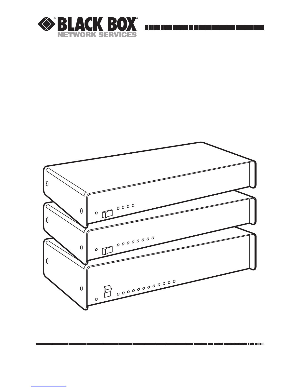
Multiport Spooler VIII (4/8/12-Port Models)
PO
W
ER
MULTIPORT SPOOLER VIII
1
2
3
4
5
6
7
8
9
10
11
12
P
O
W
E
R
1
2
3
4
5
6
7
8
MULTIPORT SPOOLER VIII
P
O
W
ER
1
2
3
4
MULTIPORT SPOOLER VIII
Page 3

FEDERAL COMMUNICATIONS COMMISSION
AND
INDUSTRY CANADA
RADIO FREQUENCY INTERFERENCE STATEMENTS
This equipment generates, uses, and can radiate radio frequency energy
and if not installed and used properly, that is, in strict accordance with the
manufacturer’s instructions, may cause interference to radio communication.
It has been tested and found to comply with the limits for a Class A
computing device in accordance with the specifications in Subpart J of
Part 15 of FCC rules, which are designed to provide reasonable protection
against such interference when the equipment is operated in a commercial
environment. Operation of this equipment in a residential area is likely to
cause interference, in which case the user at his own expense will be required
to take whatever measures may be necessary to correct the interference.
Changes or modifications not expressly approved by the party responsible
for compliance could void the user’s authority to operate the equipment.
This digital apparatus does not exceed the Class A limits for radio noise emission from
digital apparatus set out in the Radio Interference Regulation of Industry Canada.
Le présent appareil numérique n’émet pas de bruits radioélectriques dépassant les limites
applicables aux appareils numériques de classe A prescrites dans le Règlement sur le
brouillage radioélectrique publié par Industrie Canada.
FCC AND IC STATEMENTS
i
Page 4

MULTIPORT SPOOLER VIII (4-, 8-, and 12-Port Models)
NORMAS OFICIALES MEXICANAS (NOM) ELECTRICAL SAFETY STATEMENT
INSTRUCCIONES DE SEGURIDAD
1. Todas las instrucciones de seguridad y operación deberán ser leídas antes
de que el aparato eléctrico sea operado.
2. Las instrucciones de seguridad y operación deberán ser guardadas para
referencia futura.
3. Todas las advertencias en el aparato eléctrico y en sus instrucciones de
operación deben ser respetadas.
4. Todas las instrucciones de operación y uso deben ser seguidas.
5. El aparato eléctrico no deberá ser usado cerca del agua—por ejemplo,
cerca de la tina de baño, lavabo, sótano mojado o cerca de una alberca,
etc.
6. El aparato eléctrico debe ser usado únicamente con carritos o pedestales
que sean recomendados por el fabricante.
7. El aparato eléctrico debe ser montado a la pared o al techo sólo como
sea recomendado por el fabricante.
8. Servicio—El usuario no debe intentar dar servicio al equipo eléctrico más
allá a lo descrito en las instrucciones de operación. Todo otro servicio
deberá ser referido a personal de servicio calificado.
9. El aparato eléctrico debe ser situado de tal manera que su posición no
interfiera su uso. La colocación del aparato eléctrico sobre una cama,
sofá, alfombra o superficie similar puede bloquea la ventilación, no se
debe colocar en libreros o gabinetes que impidan el flujo de aire por los
orificios de ventilación.
10. El equipo eléctrico deber ser situado fuera del alcance de fuentes de
calor como radiadores, registros de calor, estufas u otros aparatos
(incluyendo amplificadores) que producen calor.
ii
Page 5

NOM STATEMENT
11. El aparato eléctrico deberá ser connectado a una fuente de poder sólo
del tipo descrito en el instructivo de operación, o como se indique en el
aparato.
12. Precaución debe ser tomada de tal manera que la tierra fisica y la
polarización del equipo no sea eliminada.
13. Los cables de la fuente de poder deben ser guiados de tal manera que no
sean pisados ni pellizcados por objetos colocados sobre o contra ellos,
poniendo particular atención a los contactos y receptáculos donde salen
del aparato.
14. El equipo eléctrico debe ser limpiado únicamente de acuerdo a las
recomendaciones del fabricante.
15. En caso de existir, una antena externa deberá ser localizada lejos de las
lineas de energia.
16. El cable de corriente deberá ser desconectado del cuando el equipo no
sea usado por un largo periodo de tiempo.
17. Cuidado debe ser tomado de tal manera que objectos liquidos no sean
derramados sobre la cubierta u orificios de ventilación.
18. Servicio por personal calificado deberá ser provisto cuando:
A: El cable de poder o el contacto ha sido dañado; u
B: Objectos han caído o líquido ha sido derramado dentro del
aparato; o
C: El aparato ha sido expuesto a la lluvia; o
D: El aparato parece no operar normalmente o muestra un cambio en
su desempeño; o
E: El aparato ha sido tirado o su cubierta ha sido dañada.
iii
Page 6

MULTIPORT SPOOLER VIII (4-, 8-, and 12-Port Models)
TRADEMARKS USED IN THIS MANUAL
Apple and Macintosh are registered trademarks of Apple Computer, Inc.
AutoCAD is a registered trademark of Autodesk, Inc.
Hercules is a registered trademark of Hercules Computer Technology.
AT, IBM, and PS/2 are registered trademarks, and PC/XT is a trademark,
of IBM Corporation.
Microsoft and MS-DOS are registered trademarks, and Windows is a
trademark, of Microsoft Corporation.
Novell is a registered trademark of Novell Incorporated.
WinFax is a registered trademark of Delrina Technology, Inc.
All other trademarks are the property of their respective owners.
iv
Page 7

v
TABLE OF CONTENTS
Contents
Chapter Page
1. Specifications ............................................................................................. 1
1.1 Requirements ...................................................................................... 1
1.2 Conformity .......................................................................................... 2
1.3 Input/Output Characteristics ........................................................... 2
1.4 Hardware Characteristics ................................................................... 3
2. Introduction ............................................................................................... 5
3. Hardware Installation ................................................................................ 6
3.1 System Requirements .......................................................................... 6
3.2 The Complete Multiport Spooler VIII .............................................. 6
3.3 Copying the Software Diskettes .......................................................... 7
3.4 Installing the Hardware ...................................................................... 7
3.5 Powering Up the System ..................................................................... 8
3.6 What To Do Next ................................................................................ 9
3.7 Using the MPSSETUP Program ....................................................... 11
4. Configuration ........................................................................................... 13
4.1 Do You Need to Configure the Multiport Spooler VIII? ................ 13
4.2 Starting the Configuration Program ............................................... 14
4.3 Defining the Command Port ........................................................... 15
4.4 The Main Menu ................................................................................ 16
4.5 Loading a Configuration .................................................................. 17
4.6 Multiport Spooler VIII Port Configuration ..................................... 18
4.7 Choosing and Changing Port Parameters ....................................... 21
4.8 Other Main Menu Selections ........................................................... 38
5. DOS Software Installation: UCTP and MPSDOS .................................... 42
5.1 The UCTP Menu and MPSDOS ....................................................... 42
5.2 The Installation Procedure .............................................................. 43
5.3 Installation Screens ........................................................................... 45
5.4 Changing MPSDOS Settings ............................................................ 56
6. Windows Software Installation: UCTP and MPSWIN ............................ 58
6.1 The UCTP Menu and MPSWIN ....................................................... 58
6.2 The Installation Procedure .............................................................. 59
6.3 Installation Screens ........................................................................... 61
6.4 Changing MPSWIN Settings ............................................................. 69
Page 8

vi
MULTIPORT SPOOLER VIII (4-, 8-, and 12-Port Models)
Chapter or Appendix Page
7. Operation ................................................................................................. 71
7.1 MPS-VIII Hardware Operation ........................................................ 71
7.2 Using MPSDOS and MPSWIN with the MPS-VIII............................. 73
7.3 Using the UCTP with the MPS-VIII .....................................................75
7.4 Operating Daisychained or Cascaded MPS-VIIIs ............................ 83
8. Troubleshooting ...................................................................................... 85
8.1 Common Concerns ........................................................................... 85
8.2 Errors Indicated by the MPS-VIII’s LEDs ........................................ 90
8.3 Non-Error Display Codes .................................................................. 92
8.4 Error Messages .................................................................................. 93
8.5 Operation-Time MPSDOS Errors: The CHKERR Program ........... 96
8.6 Calling Black Box .............................................................................. 97
8.7 Shipping and Packaging ................................................................... 97
Appendix A: Cable Pinouts ............................................................................ 98
A.1 Cable Information ............................................................................ 98
A.2 Various Connector Types ................................................................. 98
A.3 Telephone Cables and Modular Adapters .................................... 103
A.4 Parallel Cables ................................................................................. 112
Appendix B: Quick Reference: Direct Commands and Display Codes ..... 114
Appendix C: Software Files and Utilities ..................................................... 118
C.1 Files on the Included Diskettes ...................................................... 118
C.2 Files Created During Installation ................................................... 123
Appendix D: Sending Direct Commands to the MPS-VIII ......................... 130
D.1 Transmission Methods .................................................................... 131
D.2 Command Formats ......................................................................... 133
D.3 Command Descriptions .................................................................. 137
Appendix E: Editing the UCTP ................................................................... 149
Appendix F: Sharing a Fax Modem ............................................................. 152
F.1 Installing Fax Software on the First PC ......................................... 152
F.2 Hardware Connections ................................................................... 152
F.3 Installing MPSWIN ......................................................................... 153
F.4 Subsequent Installations ................................................................. 154
Appendix G: Installing and Operating Win95 Software ................................155
Page 9

1
CHAPTER 1: Specifications
1.1 Requirements
System Hardware
Required — Connected computers: IBM PC, PC/XT, AT, or PS/2
with VGA, EGA, CGA, or Hercules video adapters
System Software
Required — Connected computers: DOS version 2.0 or higher;
If running MPSWIN software: Windows
version 3.0, 3.1, or 3.11
System Memory
Required — For default configuration with no peripheral
switching: None;
To run MPSDOS: 6 KB RAM;
To run UCTP: 32 KB RAM (Hercules or CGA
adapter) or 39 KB RAM (EGA or VGA adapter);
To run MPSWIN: Brief loads of 15-KB driver
System Disk Space
Required — Will depend on software selected for installation (use
the numbers below as approximate guidelines only);
For default configuration with no peripheral
switching: None;
For UCTP only (under DOS): 91 KB minimum;
For UCTP only (under Windows): 104 KB minimum;
For DOS software only: 199 KB minumum;
For UCTP and DOS software: 289 KB minumum;
For UCTP and Windows software: 501 KB minimum;
For all software: 722 KB minimum
Cable Required — See Appendix A
1. Specifications
Page 10

2
MULTIPORT SPOOLER VIII (4-, 8-, and 12-Port Models)
1.2 Conformity
Compliance — FCC Part 15 Class A; IC Class/classe A
1.3 Input/Output Characteristics
Interfaces — PI750-2, PI760-2 models: IBM PC (Centronics
compatible) parallel only;
PI754, PI764 models: EIA RS-232 serial only;
All other models: IBM PC parallel and EIA RS-232 serial
Protocol — Serial ports: Asynchronous
Data Format — Serial ports: 7 or 8 data bits; 1 or 2 stop bits; even,
odd, or no parity (user-selectable);
Parallel ports: 8 data bits
Flow Control — Serial ports: Hardware (DTR/CTS) or software
(X-ON/X-OFF) (user-selectable); users can also
select alternate characters for software flow control
Operation Mode — Serial ports: Full duplex
Data Rate — Serial ports: 38,400, 19,200, 9600, 4800, 2400, 600,
or 300 bps (user-selectable);
Parallel ports:
Input only: Up to 36,400 cps;
Output only: Up to 18,300 cps;
Simultaneous input and output: Up to 11,900 cps
Maximum
Distance — Parallel:
From PC to MPS-VIII: Up to 100 ft. (30.5 m) across
low-capacitance cable;
From MPS-VIII to printer: Up to 25 ft. (7.6 m);
Serial:
At 38,400 bps: Up to 500 ft. (152.4 m) from PC to
MPS-VIII or from MPS-VIII to printer;
At 9600 bps: Up to 1000 ft. (304.8 m) from PC to
MPS-VIII or from MPS-VIII to printer
Page 11

3
CHAPTER 1: Specifications
1.4 Hardware Characteristics
Internal Memory — All units: 8 KB battery-backed-up static RAM for
configuration storage;
PI75X models: 1 MB buffer RAM, of which 16 KB
is reserved for use by the system;
PI76X models: 4 MB buffer RAM, of which 16 KB
is reserved for use by the system;
Buffer memory is user-allocatable to parallel or
bidirectional serial ports in 16-KB increments, or
is dynamically allocated by the unit on a first-come,
first-served basis
User Controls — Software (included);
Front-mounted ON/OFF rocker switch
Indicators — Front-mounted LEDs:
All models: (1) Power;
PI750, PI754, PI760, PI764 models:
(4) Communication Activity (one for each port);
PI751, PI755, PI761, PI765 models:
(8) Communication Activity (one for each port);
PI752, PI756, PI762, PI766 models:
(12) Communication Activity (one for each port)
Connectors — (1) Rear-mounted IEC 320 male power inlet;
Rear-mounted DB25:
PI750, PI760 models: (4) female (parallel);
PI751, PI761 models: (8) female (parallel);
PI752, PI762 models: (12) female (parallel);
PI754, PI764 models: (4) male (serial);
PI755, PI765 models: (4) female (parallel), (4) male
(serial);
PI756, PI766 units: (8) female (parallel), (4) male
(serial)
Temperature
Tolerance — Operating: 32 to 100˚ F (0 to 37.8˚C)
Storage: –40 to 212˚F (–40 to 100˚C)
Humidity
Tolerance — Up to 90% noncondensing
Page 12

4
MULTIPORT SPOOLER VIII (4-, 8-, and 12-Port Models)
Power — “A”-suffix units (PI750A, PI751A, etc.):
From wallmount power supply:
Input: 90 to 132 VAC, 50 to 60 Hz;
Consumption:
PI750A, PI754A, PI760A, PI764A models:
12.7 VA;
PI751A, PI755A, PI761A, PI765A models:
17 VA;
PI752A, PI756A, PI762A, PI766A models:
19.2 VA;
“AE”-suffix units (PI750AE, PI751AE, etc.):
From desktop power supply:
Input: 203 to 237 VAC, 50 to 60 Hz;
Consumption:
4-port models: 11.5 VA;
8-port models: 16.1 VA;
12-port models: 22 VA
Size — PI750, PI754, PI760, PI764 models:
2"H x 17.5"W x 12"D (5.1 x 44.5 x 30.5 cm);
PI751, PI755, PI761, PI765 models:
2.8"H x 17.5"W x 12"D (7 x 44.5 x 30.5 cm)
PI752, PI756, PI762, PI766 models:
3.2"H x 17.5"W x 12"D (8.1 x 44.5 x 30.5 cm)
Weight — PI750, PI754, PI760, PI764 models: 8 lb. (3.6 kg);
PI751, PI755, PI761, PI765 models: 8.8 lb. (4 kg);
PI752, PI756, PI762, PI766 models: 12 lb. (5.5 kg)
Page 13

5
CHAPTER 2: Introduction
This manual tells you how to use the 4-, 8-, and 12-port models of the
Multiport Spooler VIII (MPS-VIII) peripheral sharer and its included
MPSDOS and MPSWIN print-control software.
The Multiport Spooler VIII is a sophisticated peripheral sharer based on
multiple microprocessors. It helps you increase the effectiveness of your office
hardware by allowing several computers to share a given peripheral (such as
a printer, plotter, modem, etc.), or by giving a computer access to several of
these peripherals. The MPS-VIII enables you to cross-connect your hardware,
and thus maximize its effectiveness. Its large RAM buffer speeds up processing,
thus shortening delays often associated with computers submitting a print or
plot file.
MPSDOS and MPSWIN software enable you to select a printer or other
peripheral without having to exit your application or memorize the MPS-VIII
port to which each peripheral is connected. With MPSDOS, you can select any
of up to 11 printers from a DOS application, and with MPSWIN, any of up to
9 printers from a Windows™ application.
Whether you are in a DOS or Windows environment, you can use the
User’s Command Transmission Program (UCTP) to send commands to the
MPS-VIII, including commands to select peripherals, without having to exit
your application.
2. Introduction
Page 14

6
MULTIPORT SPOOLER VIII (4-, 8-, and 12-Port Models)
This chapter tells you the initial steps to take to set up your Multiport Spooler
VIII. These instructions complement the Easy Installation Guide included in
your package.
NOTE
These instructions are intended for the system administrator responsible
for installing the Multiport Spooler VIII. Users not involved in the
installation can refer to Chapter 7 for instructions on how to use the
MPS-VIII.
3.1 System Requirements
To use the Multiport Spooler VIII, you must have IBM®PC, PC/XT™, AT®,
PS/2®, or truly compatible computers, each with VGA, EGA, CGA, or Hercules
®
display adapters, running DOS (including MS-DOS®, PC-DOS, and Novell
®
DOS) version 2.0 or higher. If you are using MPSWIN, your computers must
also be running Microsoft®Windows version 3.0, 3.1, or 3.11.
3.2 The Complete Multiport Spooler VIII Package
As you carefully unpack the Multiport Spooler VIII, make sure you’ve received
all of the following items:
• (1) Multiport Spooler VIII main unit.
• (1) AC power adapter.
• (1) Serial or parallel cable (depending on whether port #1
on your Spooler is a serial or parallel port).
• (1) 31⁄2-inch (720-KB) software diskette labeled “Disk 1 of 2”
that contains MPSDOS and the DOS version of the UCTP.
• (1) 31⁄2-inch (1.44 MB) software diskette labeled “Disk 2 of 2”
that contains MPSWIN and the Windows version of the UCTP.
• (1) Foldout Easy Installation Guide.
• This manual.
3. Hardware Installation
Page 15

7
CHAPTER 3: Hardware Installation
3.3 Copying the Software Diskettes
Before proceeding with the software installation, we recommended that you
make a backup copy of the included software diskettes. Install from the
backup copies and store the originals.
Under DOS, you can use the DISKCOPY or COPY commands to make the
backup diskettes. Under Windows, you can use the Windows File Manager (in
the Main program group) to make the copies: From the File Manager’s Disk
menu, choose “Copy Disk,” then follow the instructions on the screen. If
necessary, refer to your DOS or Windows manual for instructions.
3.4 Installing the Hardware
Make sure to turn off and unplug the Multiport Spooler VIII, as well as the
PCs and peripherals you want to attach to it, before you install the MPS-VIII.
Refer to the included Easy Installation Guide for specific information about
port connections in the default setup of your unit. The guide shows that every
fourth port (4, 8, 12) is an output port. Use appropriate cables (see Appendix
A) to connect printers, plotters, or other peripherals that receive data to these
output ports. By default, the other ports are input ports (or bidirectional, if
your MPS-VIII model has serial ports). Use appropriate cables (see Appendix
A) to connect the computers, which mainly send data, to these input ports.
Do not plug in or turn on any of the peripherals or PCs you connect until
after you have configured the MPS-VIII.
It is important to make sure that you connect parallel ports on peripherals and
PCs to parallel ports on the MPS-VIII, and serial ports on peripherals and PCs to
serial ports on the MPS-VIII. The MPS-VIII’s parallel ports are DB25 female
connectors and its serial ports are DB25 male connectors, as shown below.
Keep in mind that the MPS-VIII’s serial ports are bidirectional, and can be
used as either input or output ports without your having to specially configure
the MPS-VIII.
DB25 Male Serial Ports DB25 Female Parallel Ports
Page 16

8
MULTIPORT SPOOLER VIII (4-, 8-, and 12-Port Models)
If your peripherals require more output-port connections than you have
output ports on your Multiport Spooler VIII, connect these peripherals to
free input ports. You can later use the configuration program to change these
ports to output ports. The opposite also applies; if your PCs require more
input ports than you have on your MPS-VIII, connect these PCs to free output
ports and later configure the unit to change the direction of the ports.
3.5 Powering Up the System
Plug the included AC power supply into the appropriate connector on the
rear panel of the Multiport Spooler VIII, then plug its input cord into a
working outlet.
The power switch is located on the front panel of the Multiport Spooler VIII.
Ideally, you should have your MPS-VIII and the attached peripherals plugged
into a common power strip or UPS, so that they can be powered up
simultaneously. If this is not the case, turn on your system in this order:
computers first, followed by the MPS-VIII, then your peripherals (printers,
plotters, modems, etc.).
When you turn on the Multiport Spooler VIII, a visual test sequence is
initiated on the front panel. If the POWER LED remains on when this test
sequence is completed, the MPS-VIII is ready for use.
Page 17

9
CHAPTER 3: Hardware Installation
3.6 What to Do Next
You have now finished your Multiport Spooler VIII’s hardware setup. Before
you go on to Section 3.7, read the passages under the following three
headings. Your answers will determine whether or not you need to install
any of the software used to control the MPS-VIII.
3.6.1 DOYOUN
EED TOCONFIGURE THE
MPS-VIII?
Depending on your specific needs, you might or might not have to configure
the Multiport Spooler VIII. Once you have connected your peripherals as
described in the Easy Installation Guide, the MPS-VIII is ready to operate
using its default configuration:
• By default, ports 4, 8, and 12 are output ports; the others are input ports
(if parallel) or bidirectional (if serial).
• The default communication parameters of the MPS-VIII’s serial ports are:
9600 bps, 8 data bits, 1 stop bit, no parity, and hardware handshaking
(DTR/CTS).
If these settings suit your needs, no further configuration is needed. If they
don’t, you need to use the configuration program to adapt the Multiport
Spooler VIII to meet your requirements (see Chapter 4).
Basically, you need to configure the Multiport Spooler VIII if:
• You have to change an input port to an output port, or vice versa.
• The communication parameters of the MPS-VIII’s serial ports do not
match those of the attached PCs and peripherals.
NOTE
You can also use the configuration program to change various userspecific functions. Refer to Section 4.7 for a full list of the parameters set
with the program and their default settings.
Page 18

10
MULTIPORT SPOOLER VIII (4-, 8-, and 12-Port Models)
3.6.2 DOYOUN
EED
MPSDOS, MPSWIN, ORUCTP?
With MPSDOS and MPSWIN software, you can select a printer (or other
peripheral) without having to exit your application or memorize the
Multiport Spooler VIII port to which each peripheral is connected. With
MPSDOS, you may select any of up to 11 printers from within a DOS
application; with MPSWIN, any of up to 9 printers from within a Windows
application. Whichever environment is used, the software is completely
transparent to the end user.
The User’s Command Transmission Program (UCTP) is a menu-driven
program available for both the DOS and Windows environments. It enables
you to send control commands to the MPS-VIII, including peripheralselection commands, without having to exit your application. You can use
these commands to do such things as specify the number of copies to print,
activate a form feed, reserve a peripheral for your exclusive use, or put your
submitted jobs on pause. You can choose to have the UCTP loaded as a
resident program, so that it’s instantly accessible by pressing a hotkey
combination. (You can also send control commands directly from the DOS
prompt, in which case you do not need the UCTP. However, this requires
knowledge of the exact command syntax, so the UCTP is recommended for
most users. Refer to Appendix D for more information about the direct
control commands.)
In summary, if your peripherals are of different types (for example, a dotmatrix printer, a laser printer, and a plotter), you need to be able to select the
appropriate peripheral (output port). Otherwise, jobs sent to the Multiport
Spooler VIII would go to the first available output port—4, 8, or 12—and the
peripheral on that port might be unsuitable for the job. Basically, you should
install one or more of these software programs if one of the following
situations applies to you:
1. You have two or more peripherals and need to be able to switch between
them.
2. You want to be able to send control commands to the Multiport Spooler
VIII.
If only situation 1 applies to you, you should install MPSDOS (see Chapter 5)or
MPSWIN (see Chapter 6), depending on which operating system you work
with. If both situations apply, you should install the UCTP (see Chapter 5 or
6); you can also install MPSDOS if you want to be able to select printers
transparently.
Page 19

11
CHAPTER 3: Hardware Installation
NOTES
1) To install the Windows UCTP menu, you need to install MPSWIN.
2) Unless you plan to work extensively in both the DOS and Windows
environments, you don’t need to do both the DOS and Windows
installations; just install the software written for the environment you use
most.
3.6.3 DOYOUN
EED THEUTILITYSOFTWARE
?
Other software utilities besides MPSDOS, MPSWIN, and the UCTP are
included with the Multiport Spooler VIII. These enable you to send a break
signal to a parallel port, change the speed of the serial port of a serially
connected computer to up to 38,400 bps, change the configuration of the
MPS-VIII if you have added memory to it, etc. These utilities are listed in
Appendix C.
It is not essential for you to determine right now whether you need some or
all of these utilities. If you prefer, you can simply install them later by using
MPSSETUP.
3.7 Using the MPSSETUP Program
You must use the MPSSETUP program if you want to:
• Configure the Multiport Spooler VIII
• Use MPSDOS or the UCTP
• Copy the other software utilities
NOTE
To install MPSWIN (including the UCTP), refer to Chapter 6.
Page 20

12
MULTIPORT SPOOLER VIII (4-, 8-, and 12-Port Models)
To execute MPSSETUP, take the following steps.
1. Insert the Multiport Spooler VIII software diskette (or its backup copy)
in your PC’s diskette drive.
2. Activate that drive by typing its letter designation followed by a colon
(for example, “A:” or “B:”) and pressing [ENTER].
3. Run the program by typing in the name “MPSSETUP” and pressing
[ENTER].
3. Based on the decisions you have made about the software you need,
select from the options displayed on the screen.
• If you need to configure the MPS-VIII, refer to Chapter 4.
• If you need to install the UCTP and/or MPSDOS, refer to Chapter 5.
• If you need to install the software utilities, you must specify the disk
drive and directory to install them to. Refer to Appendix C for more
information about the software utilities.
Page 21

13
CHAPTER 4: Configuration
4.1 Do You Need to Configure the MPS-VIII?
Whether or not you need to configure the Multiport Spooler VIII depends
entirely on your specific needs. An MPS-VIII comes with a basic factory-set
default configuration, under which every fourth port (ports 4, 8, and 12) is
an output port. Connect printers, plotters, or other peripherals that primarily
receive data to these ports. By default, the other ports are input ports (if
parallel) or bidirectional ports (if serial). Connect PCs or other devices that
primarily send data to these ports. Note that a serial bidirectional port can
serve either as an input or output port without any reconfiguration of the
MPS-VIII.
Once you have connected your peripherals, as described in Chapter 3, the
unit is fully functional according to the default settings. It only remains to
establish whether the default configuration of the Multiport Spooler VIII
meets your needs. If it does, you don’t have to configure the MPS-VIII. But
if it doesn’t, you’ll need to use the included configuration program (see
Section 4.2) or the MPS-VIII’s control commands (see Appendix D) to
adapt the Multiport Spooler VIII to meet your requirements.
Basically, you need to configure the Multiport Spooler VIII if:
• You have to change an input port to an output port, or vice versa;
• The communication parameters of the Multiport Spooler VIII serial ports
do not match those of the attached peripherals; or
• You want to change various user-specific functions. (This is optional;
among the parameters you can set are port names, port-access restriction,
headers, etc. This chapter contains a full list of the parameters that can be
set and their default settings.)
Here are some of the MPS-VIII’s important default parameters:
• By default, ports 4, 8, and 12 are output ports, and all other ports are
input (if parallel) or bidirectional (if serial) ports.
• The communications parameters of every serial port are 9600 baud, no
parity, 8 data bits, 1 stop bit, and hardware (DTR/CTS) flow control.
4. Configuration
Page 22

14
MULTIPORT SPOOLER VIII (4-, 8-, and 12-Port Models)
4.2 Starting the Configuration Program
NOTE
You can also partially configure the Multiport Spooler VIII by using the
control commands that can be sent through the User’s Command
Transmission Program (UCTP) or from the DOS command line (see
Appendix D).
To configure the Multiport Spooler VIII, you can use the MPSCONF program
included with the MPS-VIII’s support software. How you start this program
depends on whether you are configuring for the first time or have done so
before:
• If you are configuring the MPS-VIII for the first time, run the MPSSETUP
program from the MPS-VIII’s support software diskette, and choose the
Configure MPS-VIII menu selection.
• If you have configured the MPS-VIII before, using the MPSSETUP
program, MPSCONF has been copied onto your PC. Just enter the
command MPSCONF at the DOS prompt.
Regardless of how you initiate the configuration process—by selecting
Configure MPS-VIII from the MPSSETUP menu or by entering the
MPSCONF command at the DOS prompt—there are three stages to the
MPS-VIII configuration:
• Loading an existing configuration,
• Making the required modifications, and
• Saving the modified configuration.
Page 23
15
CHAPTER 4: Configuration
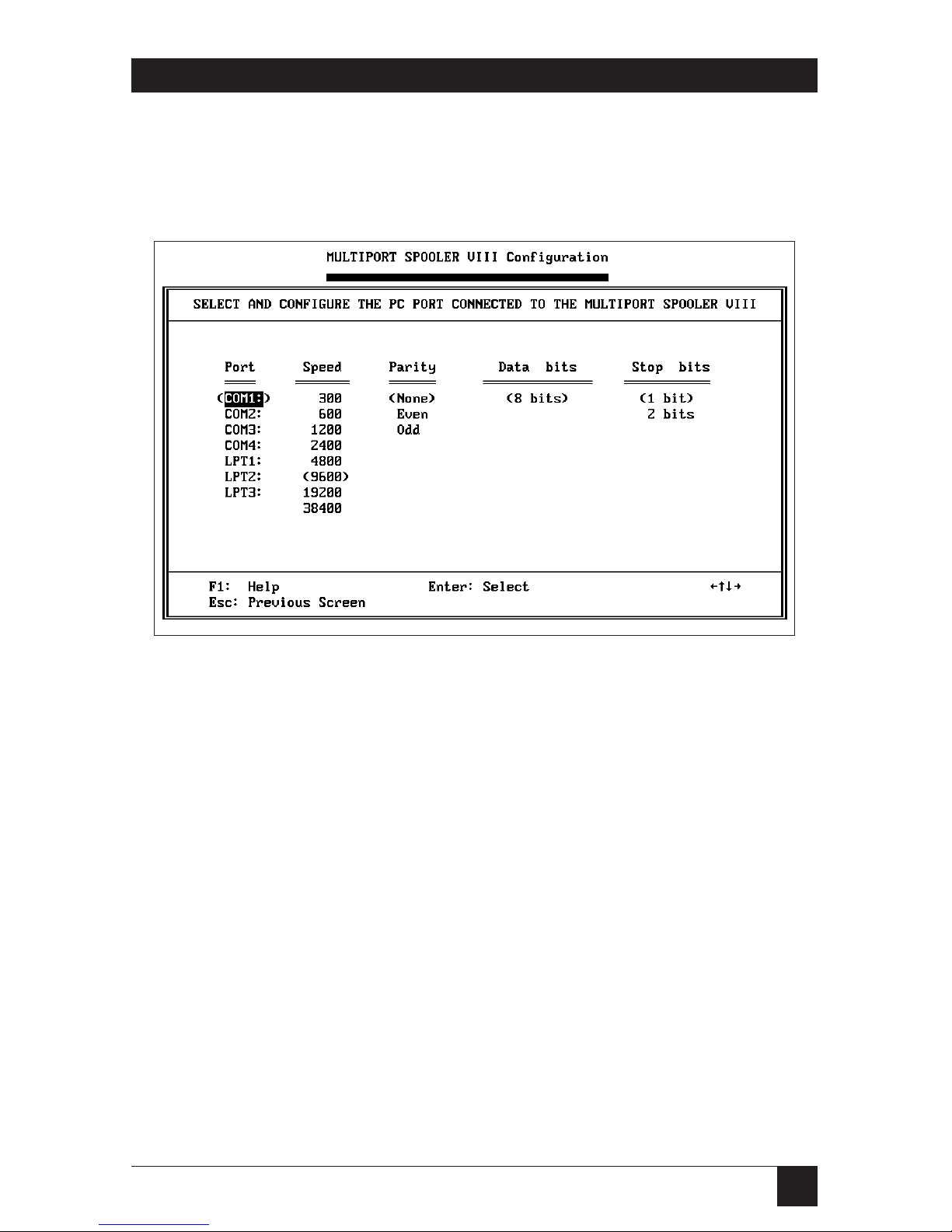
4.3 Defining the Connected Port (First-Time Configuration Only)
When you configure the Multiport Spooler VIII for the first time, you must
tell MPSCONF which one of the PC’s ports you have connected to the
Multiport Spooler VIII. This screen will appear:
Use your keyboard’s arrow keys to select the port name. The options are
serial ports COM1, COM2, COM3, or COM4, or parallel ports LPT1, LPT2,
or LPT3.
NOTE
If the PC port connected to the Multiport Spooler VIII is a serial port, the
port must be configured to the same communication parameters as the
MPS-VIII. On a new MPS-VIII, the default parameters are 9600 bps,
8 data bits, no parity, and 1 stop bit. The number of data bits is fixed at 8,
which is required for proper communication with the MPS-VIII.
Press Enter to activate your selection. The selections you make are placed in
parentheses to indicate that they are current or active. After you have defined
which PC port you are using, and have set any necessary serial communication
parameters, press Esc. You are returned to the Main Menu.
Page 24
16
MULTIPORT SPOOLER VIII (4-, 8-, and 12-Port Models)
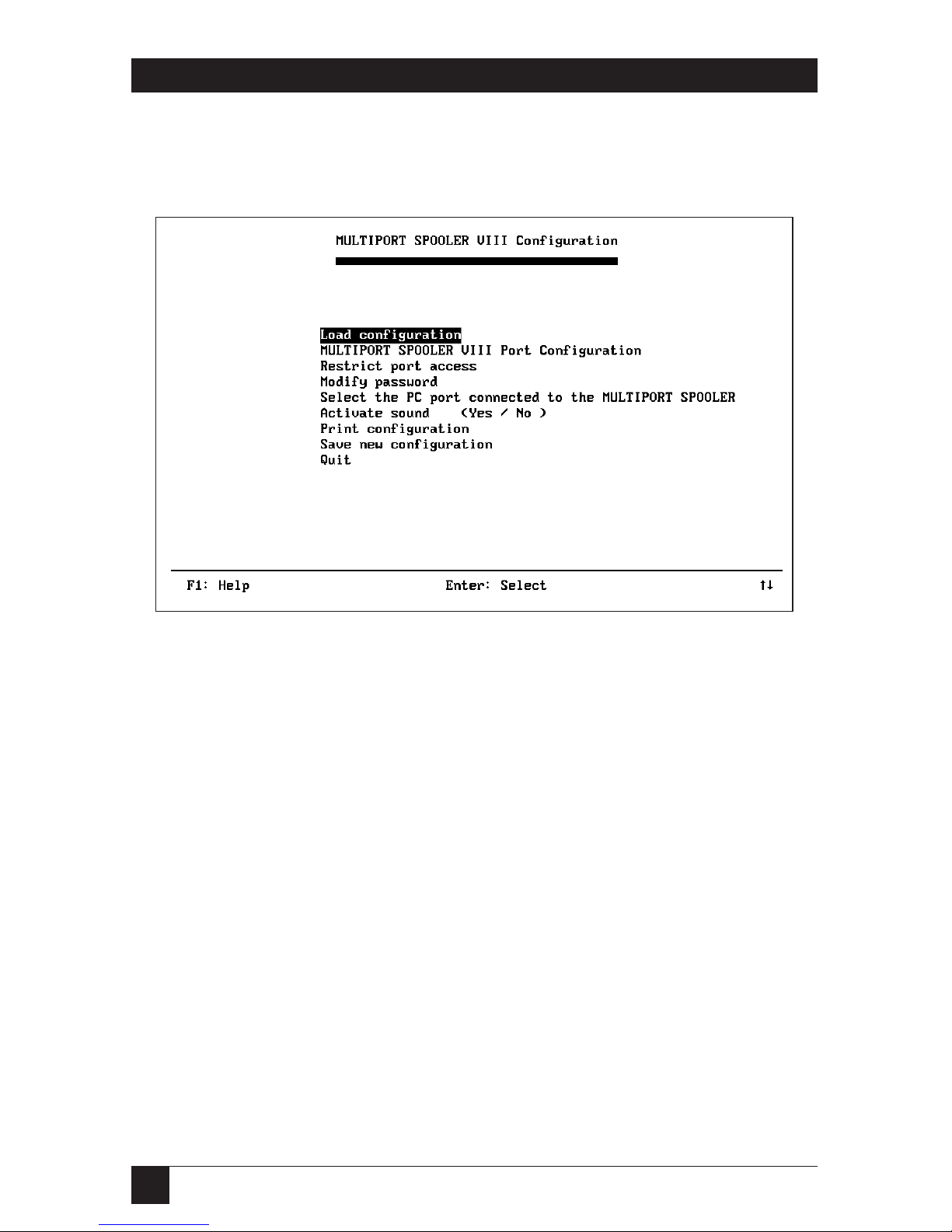
4.4 The Main Menu
The Multiport Spooler VIII’s main menu, shown below, lists the functions
involved in configuration.
Special Keys:
F1 Displays Help information
Enter Activates the option highlighted in reverse-video.
Up and down Move to the desired option.
arrow keys
To select an option from the main menu, use the up [↑] and down [↓] arrow
keys to move the reverse-video bar over the desired function, or type the first
letter of the function name. Then press Enter.
The following sections describe each of the options you can select at the
main menu.
Page 25

17
CHAPTER 4: Configuration
4.5 Loading a Configuration
To modify a configuration, whether it is the default configuration or a custom
one, you must first load (retrieve) it. When you select Load configuration at
the main menu, a screen appears and asks you to select the current
configuration (the one that is active in the MPS-VIII) or a configuration
stored in a file on disk.
• To modify the current Multiport Spooler VIII configuration, which you
must do if you are configuring the MPS-VIII for the first time, select
Configuration from Current MPS-VIII.
• To modify a configuration from a file, select Configuration from the
Disk File.
4.5.1 THEC
ONFIGURATIONPASSWORD
Whenever you load the current Multiport Spooler VIII configuration, a screen
appears and asks you to enter the configuration password. If you are loading
the default Multiport Spooler VIII configuration for the first time, there is no
password. You need only press Enter. (You can change the configuration
password by selecting Modify password at the main menu. If you have
forgotten the password, refer to the entry for “Lost Configuration Password”
in Section 8.1.)
4.5.2 THEN
AME OF THECONFIGURATIONFILE
If you are loading a configuration file from disk, you are prompted for the
configuration file’s name. You can use the Backspace key to erase the default
name NONAME. You must type in the full pathname of a disk-stored configuration file. Press Enter, and the configuration file is loaded. You are not
prompted for a password in this instance.
4.5.3 O
THERCONSIDERATIONS
If a transmission error occurs when you are loading a configuration, an error
message is displayed and the configuration is not loaded. Correct the error
and restart from the Load configuration menu option.
After the configuration is loaded, you return to the main menu with the
MULTIPORT SPOOLER VIII port configuration option highlighted.
Page 26
18
MULTIPORT SPOOLER VIII (4-, 8-, and 12-Port Models)
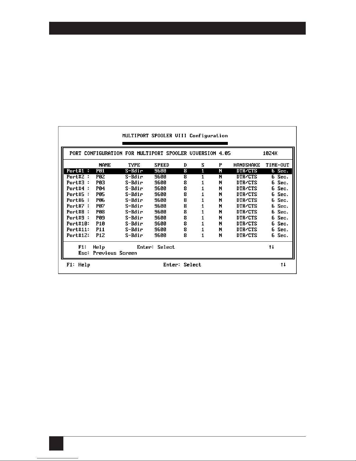
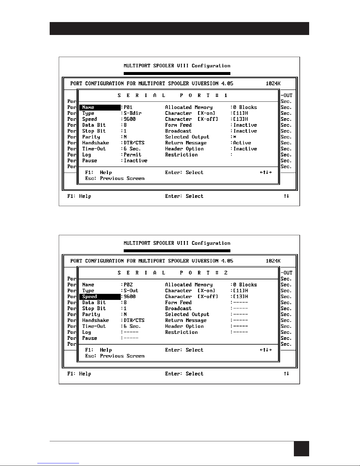
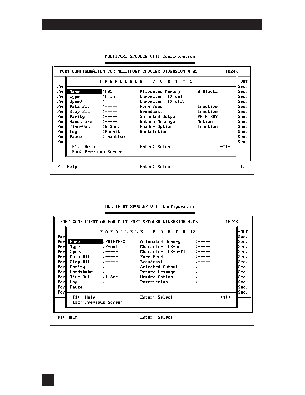
4.6 Multiport Spooler VIII Port Configuration
When you select MULTIPORT SPOOLER VIII port configuration from the
main menu, the port-menu screen shown below appears. At this screen you
can choose individual MPS-VIII ports to configure on separate screens. The
port-menu screen provides some information about the ports, such as the
port’s type and the direction of its communication. To make any changes
to a port’s configuration, however, you need to select the port and make
the changes on the corresponding screen.
Select the desired port. Press Enter and that port’s configuration screen
appears. There are four types of port-configuration screen, one for each
of the following:
• Serial bidirectional ports,
• Serial output ports,
• Parallel input ports, and
• Parallel output ports.
Examples of each type are shown on the following pages. The fields
in the port-configuration screens are described in Section 4.7.
Page 27
19
CHAPTER 4: Configuration
4.6.1 C
ONFIGURATIONSCREEN FORSERIALBIDIRECTIONALPORTS
4.6.2 C
ONFIGURATION
S
CREEN FORSERIALOUTPUTPORTS
Page 28
20
MULTIPORT SPOOLER VIII (4-, 8-, and 12-Port Models)
4.6.3 C
ONFIGURATIONSCREEN FORPARALLELINPUTPORTS
4.6.4 C
ONFIGURATION
S
CREEN FORPARALLELOUTPUTPORTS
Page 29

21
CHAPTER 4: Configuration
4.7 Choosing and Changing Port Parameters
Using the port-configuration screens on the previous pages, you can
configure any of the Multiport Spooler VIII’s ports, including the default
output ports (numbers 4, 8, and 12), to meet your needs. After selecting a
particular port, just select the parameter and change the value to the one
you prefer.
Not every parameter applies to every port. For example, serial
communication parameters (data bits, parity, etc.) apply only to serial ports.
When a parameter does not apply to a port, dashes (- - - - - ) appear in its field.
To position the highlight bar on the parameter you wish to modify, use the
up (↑), down (↓), left (←), and right (→) arrow keys, or type the first letter of
the parameter. If several parameters start with the same letter, press the letter
key until the highlight bar reaches the desired parameter. To select that
parameter, press Enter. The cursor positions itself in the value column to the
right of the parameter’s name. If the value is erased and the field is in reverse
video, type the new value and press Enter. If the value flashes, use the up and
down arrow keys to toggle between the available choices. In either case, press
Enter to confirm your entry.
The various port configuration parameters and a summary of each one’s
purpose is listed on the following page. A detailed explanation of each
parameter follows.
Page 30

22
MULTIPORT SPOOLER VIII (4-, 8-, and 12-Port Models)
4.7.1 S
UMMARY OFPORT-CONFIGURATIONPARAMETERS
Name Enter port name
Type Set port direction
Speed Set data rate
Data Bit Set number of data bits
Stop Bit Set number of stop bits
Parity Set type of parity
Handshake Set type of flow control
Time-Out Set length of timeouts
Log Permit/deny reserving peripherals
Pause Set pause between each job
Allocated Memory Assign memory to a given port
Character [X-on] Define “Continue” flow-control character
Character [X-off] Define “Stop” flow-control character
Form Feed Activate/deactivate automatic form feed
Broadcast Activate/deactivate sending jobs to all selected
output ports
Selected Output Designate output port for input port
Return Message Activate/deactivate message/command
acknowledgement
Header Option Define and activate/deactivate header
Restriction Permit/deny access by input port to output port
Page 31

23
CHAPTER 4: Configuration
4.7.2 P
ORT-CONFIGURATIONPARAMETERS INDETAIL
Name
Purpose Assigns a unique name to each port.
Applies To All port types.
Possible Values Each name can be up to 8 characters in length. The
first character cannot be a number. You can use any
ASCII keyboard character in the name except
comma (“,”), asterisk (“*”), slash (“/”), question
mark (“?”), carriage return (“Enter”), escape (“ESC”),
and “at sign” (“@”, the command-start character).
Usage Notes By default, ports 4, 8, and 12 are assigned the names
PRINTERA, PRINTERB, and PRINTERC; the other
ports are named P01 through P11. You can change
any of these. You might want to assign names based on
whether a user or peripheral is connected (for
instance, USER1 or PLOTTER2). It is advisable to
group similar peripherals with similar names to allow
easy selection with wild-card characters, if required.
For example, you can select the first available of
MODEM_A or MODEM_B with MODEM_?. No
name can be used more than once.
Type
Purpose Determines the direction of data through each port.
Applies To All port types.
Possible Values Parallel Input Ports : P-In
Parallel Output Ports: P-Out
Serial Bidirectional Ports: S-BDir
Serial Output Ports: S-Out
By default, ports 4, 8, and 12, whether serial or
parallel, are defined as output ports; all other parallel
ports are defined as input ports; and all other serial
ports are defined as bidirectional ports.
Page 32

24
MULTIPORT SPOOLER VIII (4-, 8-, and 12-Port Models)
Usage Notes Use this parameter to set ports to be input ports
(MPS-VIII ports that receive information) or output
ports (MPS-VIII ports that transmit information—for
example, a printer job—to a peripheral or to
another PC). Serial bidirectional ports can serve both
these purposes.
Your Multiport Spooler VIII has 4, 8, or 12 ports,
but depending on the model you chose, your unit
may have only parallel ports, only serial ports, or
some combination of the two types. Depending on
how you organize your PCs and peripherals and on
which MPS-VIII model you have, you can designate
some parallel ports as input and others as output,
and designate some serial ports as exclusively output
and others as bidirectional. From the opposite point
of view, input ports can be parallel input ports or
serial bidirectional ports, and output ports can be
parallel output ports, serial output ports, or serial
bidirectional ports.
Examples: You would normally set a parallel port
cabled to a PC to be an input port. You would
normally set a parallel port cabled to a printer to be
an output port. And, if you were planning for file
transfers between PCs, you would set a serial port
cabled to a PC to be a bidirectional port.
NOTE
The Form Feed and Header Option parameters
are automatically disabled when a port is
configured as an output port. However, the
settings of these disabled options stay in the
MPS-VIII’s memory. This enables users to
restore these options’ original configurations
by changing the port back to an input port.
Page 33

25
CHAPTER 4: Configuration
Speed
Purpose Determines the data rate (also called “baud rate” or
“transmission speed”) of the chosen port.
Applies To Serial ports only.
Possible Values 300, 600, 1200, 2400, 4800, 9600, 19200, or
38400 bps. Use the up and down arrow keys to toggle
from value to value. The default data rate is 9600
bps.
Usage Notes Set the data rate of the Multiport Spooler VIII port
to match the data rate of the device to which it is
connected.
NOTE
Most DOS PC serial ports default to a data rate
of 2400 bps unless they are set differently with
the DOS MODE command or the included
SMODE command (refer to Appendix D).
Data Bit
Purpose Determines the number of data bits on the chosen
port.
Applies To Serial ports only.
Possible Values 7 or 8 (8 is the default).
Usage Notes Set the data bits of the Multiport Spooler VIII port to
match the data bits of the device to which it is
connected.
If you select 7 data bits, decimal characters 128 to
255 (for example, the “extended ASCII” accented
and graphic characters) can’t be transmitted, and you
can no longer configure the MPS-VIII from this port.
However, 7-bit data with even or odd parity is similar
to 8-bit data with no parity. This can be useful if you
have a graphics package that sends 7-bit data with
even parity. You can set the Multiport Spooler VIII to
8-bit data and no parity, allowing other applications
to use the full 8-bit character set.
Page 34

26
MULTIPORT SPOOLER VIII (4-, 8-, and 12-Port Models)
Stop Bit
Purpose Determines the number of stop bits on the chosen
port.
Applies To Serial ports only.
Possible Values 1 or 2 (1 is the default).
Usage Notes Set the number of stop bits of the Multiport Spooler
VIII port to match the number of stop bits of the
device to which it is connected.
Parity
Purpose Determines the parity type.
Applies To Serial ports only.
Possible Values None, Even, or Odd (None is the default).
Usage Notes Set the parity of the Multiport Spooler VIII port to
match the parity of the device to which it is
connected.
Handshaking
Purpose Determines handshaking (flow control) protocol.
Applies To Serial ports only.
Possible Values DTR/CTS (hardware) or X-ON/X-OFF (software).
The default is DTR/CTS.
Usage Notes If you have selected software flow control, you can
choose whichever control codes you want to take the
place of the the X-ON and X-OFF characters. (This is
helpful for people who are using ENQ/ACK or other
less popular types of software flow control.) Refer to
the entries for the Character [X-on] and Character
[X-off] parameters later in this section.
Page 35

27
CHAPTER 4: Configuration
Time-Out
Purpose The timeout is the amount of non-transmitting time
that may elapse during the transmission of a job
before the Multiport Spooler VIII considers the job
to be finished. The MPS-VIII will wait the length of
the timeout for a transmission to resume without
treating it as a new transmission. After the timeout
expires, the MPS-VIII considers the next
transmission to be a new job.
Applies To All port types.
Possible Values The default timeout for parallel input ports and
serial bidirectional ports is 6 seconds. For parallel
and serial output ports, the default is 1 second. The
timeout range for any port is from 1 to 999 seconds.
Usage Notes General
The LEDs of the input and output ports are ON
during transmission and turn OFF when
transmission ends and the timeout expires.
On input ports, the expiration of the timeout
marks the end of a job received from an external
source. A timeout is relevant to output ports only
when two or more Multiport Spooler VIII units are
daisychained or cascaded (connected together; see
Section 7.4).
Input-Port Timeouts
Some software packages, such as AutoCAD®, perform
a variety of calculations while printing or plotting.
While these calculations are in process there may be
temporary pauses in data transmission. If the inputport timeout expires during such a pause, the
Multiport Spooler VIII assumes that the job has
finished, although there has actually only been a
transmission delay.
Page 36

28
MULTIPORT SPOOLER VIII (4-, 8-, and 12-Port Models)
Either of the following can happen when a timeout
expires during such a delay:
a) When transmission resumes, the Multiport
Spooler VIII assumes it has a new job, rather than a
resumption of the old job. Therefore, any form feed,
header, or character string assigned to the input port
is unnecessarily executed. Or,
b) If a new job is sent to the same output port
from a different source before transmission resumes,
the Multiport Spooler VIII switches to the new job
before completing the old one, because it thinks the
old one is finished.
Because of these possibilities, you need to set the
timeout for an input port long enough to ensure that
transmitted jobs will not be ended prematurely, but
short enough to allow other users fair access to the
same peripheral. For software packages that transmit
without interruption (for example, word-processing
software), set a 6-second timeout for the input ports.
In cases when you expect transmission interruptions
caused by disk accessing or vector processing (for
example, plotting from AutoCAD), you need to set
a longer timeout (about 30 seconds).
A direct command is recognized if it occurs within
the first 256 characters of a new job. If more than
256 characters of the same job are sent to the
Multiport Spooler VIII, the timeout on the entry
port must expire before another command can
be recognized. In this case, the timeout is used
to indicate when the MPS-VIII should interpret
command character strings as actual commands
and execute them.
To automatically reset an input-port timeout to
zero before a subsequent command is sent, use the
UCTP program to enable the Break feature (see
Section 7.3.3).
Page 37

29
CHAPTER 4: Configuration
Output-Port Timeouts
The timeout is not critical or necessary when a
Multiport Spooler VIII output port transmits to
peripherals such as a printer, plotter, or modem.
To deactivate the timeout, set it to one second.
The timeout on an output port is critical,
however, when two or more MPS-VIIIs are
daisychained or cascaded (connected to each other;
see Section 7.4). If the timeout on the sending MPS-
VIII’s output port is shorter than the timeout on the
receiving MPS-VIII’s input port, the receiving unit
might interpret a new transmission as being part of
a preceding one. Thus, two separate tasks would be
interpreted as one.
NOTE
In general, input (PC) port timeouts should be
set longer than output (peripheral) port
timeouts. Setting input-port timeouts too short
may cause errors in job processing.
Log
Purpose Determines whether PC users can reserve
peripherals for their exclusive use.
Applies To Parallel input ports and serial bidirectional
ports used as input ports.
Possible Values “Permit” or “Deny.” The default is “Permit.”
Usage Notes Users whose input port is granted the Log capability
can use the /L, /Y, or /Z direct control commands
to reserve a chosen output or bidirectional port for
their exclusive use. Users whose input port is denied
the Log capability can send these commands, but
they are ignored.
NOTE
Serial connections for modem communication
or file transfers should have the Log option
permitted.
Page 38

30
MULTIPORT SPOOLER VIII (4-, 8-, and 12-Port Models)
Pause
Purpose Sets a pause for all jobs transmitted to the Multiport
Spooler VIII through the selected port. The MPSVIII will receive user jobs intact, but will not send
them to the selected port until the user releases
the paused jobs.
Applies To Parallel input ports and serial bidirectional ports
used as input ports.
Possible Values “Active” or “Inactive.” The default is “Inactive.”
Usage Notes Setting a pause allows the user transmitting to the
Multiport Spooler VIII to refill a paper tray or
change plotter pens before the MPS-VIII processes
that job to an output port (and the attached
peripheral).
If the MPS-VIII’s buffer is full when a new job is
received, the first paused job in the queue is
automatically released to the peripheral. The pause
stays active.
When a pause is active, you must use the Release
Pause command to release a paused job. Refer to
Section 7.3.2 or the entry for the /A command in
Appendix D for details.
Allocated Memory
Purpose Sets aside a block of memory exclusively for the user
linked to the selected Multiport Spooler VIII port.
The allocated memory is never available to other
users.
Applies To Parallel input ports and serial bidirectional ports
used as input ports.
Possible Values Depend on how much memory your Multiport
Spooler VIII has (refer to the table below). The
default is 0 (zero).
Page 39

31
CHAPTER 4: Configuration
Usage Notes The Multiport Spooler VIII normally allocates
memory automatically, as required for each job.
Manually allocating memory enables you to reserve
memory exclusively for a given user. The amount you
specify is always available to that user, regardless of
the activities of other users.
Memory is allocated in single 16-KB blocks. The
number of 16-KB blocks available in your Multiport
Spooler VIII depends on the amount of memory
installed in it. The following table shows how much
memory and how many blocks are available with
various memory configurations. (Four 16-KB blocks
are always reserved for internal processing.)
Memory Capacity No. of Available
16-KB Blocks
256 KB 12
512 KB 28
1 MB 60
4 MB 252
Character [X-on], Character [X-off]
Purpose Determines the software flow-control characters.
Applies To Serial ports only.
Possible Values Any hexadecimal (hex) code between 0 and FF. The
defaults are 11 for X-ON and 13 for X-OFF.
Usage Notes If you want to, you can select alternate software flow-
control codes (if you use ENQ/ACK flow control, for
example).
Form Feed
Purpose Determines whether a form feed is automatically sent
at the beginning and/or end of each job.
Applies To Parallel input ports and serial bidirectional ports
used as input ports.
Possible Values “Active” or “Inactive.” The default is “Inactive.”
Page 40

32
MULTIPORT SPOOLER VIII (4-, 8-, and 12-Port Models)
Usage Notes This option is particularly helpful if you use the Print
Screen function. Set the timeout to 1 second and
activate the form feed. A form feed is then generated
after each print screen.
An end-of-job form feed is executed after the
timeout expires.
You can also use form feed to insert a blank page
between user printouts on a continuous-feed printer.
Broadcast
Purpose Determines whether a user can, with a single
command, send a job to all or several selected output
ports at once.
Applies To Parallel input ports and serial bidirectional ports
used as input ports.
Possible Values “Active” or “Inactive.” The default is “Inactive.”
Usage Notes If you activate Broadcast, you must specify the ports
used for broadcast in the Selected Output field (see
the description of that field below).
An example application might be a user who
needs to be able to print a document at several
different stations at the same time (to convey
information to people at those stations).
Selected Output
Purpose Specifies the output port for a Multiport
Spooler VIII input port.
Applies To Input ports.
Possible Values The name of any output (or bidirectional) port. You
can also group peripherals together by type and use
a wild-card character (“*” or “?”) to indicate that any
of the peripherals can be used. The default is
PRINTER?, which means the job goes to the first
available output port (PRINTERA, PRINTERB, or
PRINTERC at port 4, 8, or 12 respectively).
Page 41

33
CHAPTER 4: Configuration
NOTE
Just as in DOS, the “?” wild-card character
represents a single character, whereas the “*”
character can represent a string of one or
more characters.
Usage Notes Suppose Mary’s PC is connected to port #2. You can
specify port #12, which is connected to printer C, as
the selected output for port #2. Mary’s print jobs will
then go to printer C until she chooses another
printer (for example, with the UCTP, MPSDOS, or
MPSWIN).
If you enter just the wild-card character as the
selected output, all jobs from the input port go to
the first available output port, whether parallel,
serial, or serial bidirectional, unless the user specifies
otherwise. But it might be a better idea to limit the
output to a certain peripheral or peripheral type that
suits the input port’s user.
To specify the desired output port, enter its name
or number and press Enter. You cannot specify input
ports or ports that have beeen restricted with the
Restriction parameter (see the description of this
field on page 37) as selected output ports.
If all available selected output ports are busy,
the job remains in the buffer until one becomes
available.
Page 42

34
MULTIPORT SPOOLER VIII (4-, 8-, and 12-Port Models)
Return Message
Purpose Instructs the Multiport Spooler VIII to acknowledge
the commands or configurations that it receives from
the user.
Applies To Parallel input ports and serial bidirectional ports
used as input ports.
Values “Active” or “Inactive.” The default is “Active.”
Here are some of the messages that the MPS-VIII might return if Return
Message is active:
(OK) Command accepted
(UNKNOWN COMMAND) Invalid command
(CONNECTED TO ) Confirmation of bidirectional link
with port
(RESERVATION CONFIRMED Confirmation of a permanent
FOR ) unidirectional link with port
(PORT NOT VALID) The wrong port was addressed
(SYNTAX ERROR) Syntax error in the command
parameters
(UNAUTHORIZED COMMAND) Command unauthorized for the
specific link
(INVALID PASSWORD OR Command rejected due to a
PASSWORD NEEDED) missing or invalid password
(PORT NOT VALID OR BUSY) Attempt to link to a busy or invalid
port
(NEW CONFIGURATION ACTIVE) The loaded configuration is now
active (current)
(TRANSMISSION ERROR) Communication error
(CONFLICTING MEMORY SIZE) The amount of memory specified
in the configuration does not
match the amount of memory
actually installed in the unit
(WRONG MPS-VIII MODEL) The wrong MPS-VIII model is
specified in the configuration.
Page 43

35
CHAPTER 4: Configuration
Header Option
Purpose Specifies header text, activates the header (with or
without a form feed) and deactivates the header.
Headers are ideal for identifying users’ print jobs,
or sending printer- or modem-initialization strings.
Applies To Parallel input ports and serial bidirectional ports.
Possible Values Refer to the Usage Notes below.
Usage Notes When you select this option, a window containing a
menu is displayed. Choose from its three alternatives
(listed below), then confirm your selection by
entering X. The value in the port-configuration
screen changes accordingly.
Header Define: Opens another window, where you
type your header text. Header text can be a single
line of up to 60 characters. All ASCII characters are
allowed.
Header Activation: Activates the header. If you have
not defined a header, the default header is used.
This is PORT#, where is the number associated
with the input port being configured
(1 to 12). An active header is printed at the
beginning of print jobs (with or without an
automatic form feed) until you deactivate it.
Header Deactivation: Deactivates the header.
NOTE
You can use headers to specify things other
than text. For example, you can use a header
in place of the token (see Section 7.3.3) when
a command is to be applied to the second of
two daisychained Multiport Spooler VIII units
(see Section 7.4). For example, if the header is
@@/P4@, the first MPS-VIII that receives a job
forwards this header through its output port to
the second MPS-VIII, which then interprets the
header as the /P4 command.
Page 44

36
MULTIPORT SPOOLER VIII (4-, 8-, and 12-Port Models)
Restriction
Purpose Enables you to permit or deny access from an input
port to an output port. You can use this option to
determine who can use which peripherals.
Applies To Parallel input ports and serial bidirectional ports
used as input ports.
Possible Values X (access) or a blank (no access). The default is X.
When you select this option, this window appears:
Page 45

37
CHAPTER 4: Configuration
Usage Notes The upper row of port numbers lists all ports in the
unit; the lower row of X’s and blanks indicates the
user’s port. An X indicates the user can select the
port. Use the arrow keys to move to the port that
you want to change and press Enter to toggle its
restriction status.
Thus, the Selected Output parameter establishes
the output ports to which a user’s job will be directed,
whereas the Restriction parameter establishes the
output ports to which a user’s job can be directed.
For example, User A inputs to P02, which has P12
as its Selected Output. P12 is attached to a printer,
which is thus User A’s printer. However, P02 is
granted unrestricted access to P08, an output port
attached to a plotter. When desired, therefore, User
A can send a job to P08, the plotter.
Page 46

38
MULTIPORT SPOOLER VIII (4-, 8-, and 12-Port Models)
4.8 Other Main Menu Selections
Once you have established port parameters, you are returned to the main
menu. If you choose, you can use the menu’s other functions to change
various settings.
4.8.1 R
ESTRICTPORTACCESS
The Multiport Spooler VIII administrator can use this function to permit or
deny the various input ports (users) access to parallel and serial output ports
and serial bidirectional ports serving as output ports.
This function is essentially identical to the Restriction parameter on the
port-configuration screen (see the entry for this parameter on page 37). The
only difference is that the main-menu function gives a more global picture of
output-access privileges.
When you select this function, this window appears:
Select the desired output port and press Enter to toggle its restriction status.
An X indicates that the port in the same row (listed in the column on the lefthand side of the screen) has free access to the port in the same column (listed
in the rown at the top of the screen). For example, in the screen shown
above, Port 1 has access to Ports 2 through 8 and 12; Port 2 has access to Ports
1, 3 through 8, and 12; and so forth.
Page 47

39
CHAPTER 4: Configuration
4.8.2 M
ODIFYPASSWORD
Use this function to set or change the Multiport Spooler VIII’s configuration
password. By default there is no password. Using a password helps to prevent
unauthorized users from changing the MPS-VIII’s configuration.
A password can contain up to 16 characters, including any ASCII character
except “Enter,” “Esc,” “/,” and the command-start character “@”. You are
required to enter the password a second time for verification purposes.
NOTE
If you have forgotten your password, refer to Section 8.1.
4.8.3 S
ELECT THE
PC P
ORTCONNECTED TO THEMULTIPORTSPOOLER
VIII
Use this function to tell MPSCONF which of the PC’s I/O ports you are
using to communicate with the Multiport Spooler VIII. If you are connected
through a serial port (COM1, COM2, etc.), you can change the data rate,
parity, and number of stop bits. (This function has no facility for changing
the data bits, because 8 data bits are required to send binary configuration
information to the MPS-VIII, and we recommend the 8-data-bit setting for
other serial communication.)
The window that appears when you select this function is the same window
that appears when you first configure the Multiport Spooler VIII and select
the PC port connected to it (see Section 4.3).
4.8.4 A
CTIVATESOUND(YES/NO
)
Use the Activate sound selection to activate or deactivate the audible signals
generated when a window is opened or closed. The default setting is Y (“Yes,”
activated). To change the status, use the arrow keys to position the highlight
bar over the menu selection and press Enter.
4.8.5 P
RINTCONFIGURATION
If you want to print the Multiport Spooler VIII’s configuration, select the
Print configuration function at the main menu. You can print the saved
configuration, the revised configuration (if you’ve changed it but haven’t
saved it yet), or a summary of the revised configuration.
Page 48

40
MULTIPORT SPOOLER VIII (4-, 8-, and 12-Port Models)
4.8.6 S
AVENEWCONFIGURATION
Select Save new configuration to save a revised configuration either to the
Multiport Spooler VIII’s static RAM or to a PC file:
• To replace the current saved configuration with the revised configuration,
select the Change the Multiport Spooler VIII configuration option at the
window that appears. You will be prompted to enter the password of the
configuration being replaced. A New Configuration Active message will
be displayed when the configuration is successfully stored.
NOTES
When you save a configuration to the Multiport Spooler VIII’s static RAM,
the current configuration is revised immediately and the unit is
reinitialized. Any jobs that the MPS-VIII was processing are lost.
Therefore, do not change the current configuration during any
transmissions to or from the MPS-VIII.
The Save new configuration option uses one block of the MPS-VIII’s
memory to transfer configurations to the MPS-VIII. If all of a unit’s
memory blocks are in use or reserved, you will not be able to save a
configuration to that unit.
• To generate a file containing the configuration, choose the Save revised
configuration to disk option at the window that appears. No password is
required. MPSCONF prompts you for a name; it supplies the default
name NONAME, which you can change if you wish. MPSCONF
automatically appends the extension .BW.
NOTE
Modifications made to a loaded configuration are not retained unless you
save it either in the Multiport Spooler VIII or as a file on disk.
If your attempt to save a configuration to the MPS-VIII is unsuccessful, one
of the following messages may point to the problem:
Wrong MPS-VIII Model
The type of Multiport Spooler VIII listed in your configuration does not
match the MPS-VIII you are trying to save the configuration to. This is
normally caused by trying to modify one of several configurations for
different units saved on the same disk and choosing the wrong one. Load an
appropriate configuration for the desired model, or load the configuration
currently saved in the unit, and modify and save that.
Page 49

41
CHAPTER 4: Configuration
Conflicting Memory Size
There is a conflict between the memory listed in the configuration and the
Multiport Spooler VIII’s actual memory capacity. This is normally caused by
trying to save a configuration to the MPS-VIII after more memory has been
physically installed in the unit. First, save the revised configuration to a disk
file; if this is not possible, you will have to abandon your revisions and redo
them later. Use the UPDATE utility (see Appendix C) to update the
configuration saved in the MPS-VIII so that it reflects the added memory.
Then reload the new configuration from disk (or reload the old
configuration from the MPS-VIII and redo your changes) and try saving
the new configuration to the MPS-VIII again.
Transmission Error
An error occurred when the PC tried to transmit the revised configuration to
the Multiport Spooler VIII. Verify that the proper cables are securely attached
to the PC and to the MPS-VIII. If the MPS-VIII is cabled to one of the PC’s
serial ports (COM1, COM2, etc.), make sure that the serial port’s
communication parameters (data rate, parity, etc.) match those of the
MPS-VIII’s input port. Note that the PC’s serial port must be set for eight data
bits in order to send an MPS-VIII configuration to a PC file.
If any of these errors occurs, the configuration saved in the Multiport Spooler
VIII remains unchanged, and the unit is not reinitialized.
4.8.7 Q
UIT
Use Quit to exit the MPSCONF program. If you loaded a configuration, you
are asked whether you wish to save the configuration to disk or send it to the
Multiport Spooler VIII for saving in its static RAM.
Alternatively, you can abandon the configuration and return to DOS.
Page 50

42
MULTIPORT SPOOLER VIII (4-, 8-, and 12-Port Models)
5.1 The UCTP Menu and MPSDOS
This chapter explains how to install the Users’ Command Transmission
Program (UCTP) and the MPSDOS print-utility software for users working
in a DOS environment.
NOTE
This chapter describes software installation for users who plan to work
in a DOS environment. If you plan to work in a Windows environment,
refer to Chapter 6. Refer to Chapter 7 for instructions for operating the
MPS-VIII with MPSDOS and the UCTP.
With the UCTP running, you can access a pop-up menu from within your
applications to send control commands to the Multiport Spooler VIII,
including commands for selecting peripherals. You can use these commands
to do such things as specify the number of copies to print, activate a form
feed, reserve a peripheral for your exclusive use, or put your submitted jobs
on pause. You can also customize the UCTP menu to fit your needs (refer to
Appendix E).
MPSDOS software greatly enhances the ease with which you can select a
printer (or another peripheral). You can select from up to 11 printers without
having to exit your application or memorize which MPS-VIII port each printer
is connected to.
If you are connecting different kinds of peripherals to the Multiport
Spooler VIII (for example, a dot-matrix printer, a laser printer, and a plotter),
your users need to be able to select the appropriate peripheral. Otherwise,
jobs sent to the MPS-VIII would go to the first available output port—4, 8, or
12—and the peripheral attached to that port might be unsuitable for the job.
Therefore, you should install the software if:
1. You have two or more peripherals and need to be able to switch between
them, or
2. You want to be able to send control commands to the MPS-VIII.
If only number 1 applies to you, you should install MPSDOS. If both apply to
you, you should install the UCTP; if you want transparent printer selection, you
can also install MPSDOS.
5. DOS Software Installation:
UCTP and MPSDOS
Page 51

43
CHAPTER 5: DOS Software Installation: UCTP and MPSDOS
5.2 The Installation Procedure
To install the UCTP and/or MPSDOS, take the following steps (refer to
Section 5.3 for full details):
1. Insert the Multiport Spooler VIII’s diskette labeled “Disk 1 of 2” in one
of your PC’s diskette drives.
2. Switch to that drive by typing its letter designation followed by a colon
(“A:”, for example).
3. Type MPSSETUP and press Enter. The installation program begins to
run.
Here are some of the keys you can use to control the installation process
within MPSSETUP:
Tab To go to the next option
Shift-Tab To go back to the previous option
Alt- To select the option with an underlined letter ()
Enter To accept an entry and go to the next option
Up-Arrow To move up in the option list
Down-Arrow To move down in the option list
Esc To return to the previous screen
F1 Help
F3 Exit the Installation Program
A field’s highlighted value becomes the active one. When you have
finished selecting, tab to the Continue field and press Enter.
The screens that appear during installation depend on whether you
choose to install the UCTP or MPSDOS or both. They are described in
detail in Section 5.3.
NOTE
Only those screens that require you to enter data are shown in
illustrations in this chapter. For brevity’s sake, we didn’t include pictures
of screens that only require you to respond with a Yes or a No or enter
other simple information. The manual does include all the relevant
information about these screens.
4. Select UCTP and/or MPSDOS from the menu that appears, then press
Enter.
5. Select the drive that contains the MPS-VIII diskette, as well as the drive
and directory where you want the software to be installed.
Page 52

44
MULTIPORT SPOOLER VIII (4-, 8-, and 12-Port Models)
6. Tell MPSSETUP which of the PC’s ports is connected to the MPS-VIII.
If the connected PC port is a serial port, set the port’s parameters.
7. Tell MPSSETUP which MPS-VIII model is connected to the PC.
8. If you are installing the UCTP, proceed to Step 9. If you aren’t, go to
Step 12.
9. Choose the UCTP menu level.
10. Decide whether or not the UCTP will function as a resident (TSR)
or nonresident program.
11. Choose the video interface, set the break, set the token, and select
hotkeys.
12. If you are installing MPSDOS, proceed to Step 13. If you aren’t, go to
Step 17.
13. Set the redirection for each port, and (if you want to) define strings for
the ports.
14. Set the timeout.
15. Choose whether or not returned messages will be verified.
16. If you want to, select a port and print its configuration.
17. Confirm the installation.
18. Return to DOS or reboot the PC.
This completes the installation process. From this point on, you should
able to select output (printer) ports from inside your applications.
Page 53

45
CHAPTER 5: DOS Software Installation: UCTP and MPSDOS
5.3 Installation Screens
5.3.1 I
NITIALSCREEN
(UCTP
AND
MPSDOS)
Source
Enter the letter designation of the drive containing the MPS-VIII diskette.
Destination
This is the drive and directory where the software will be installed. The
default C:\MPSVIII is displayed. Press Enter if this is acceptable. If you want
to, enter a different drive or directory. Remember to include the drive letter
before the directory name. You must install onto a hard disk.
5.3.2 PC P
ORTPARAMETERSSCREEN
(UCTP
AND
MPSDOS)
At this screen (shown below), set the parameters of the PC port connected
to the Multiport Spooler VIII. The parameters must match those of the
corresponding MPS-VIII port.
Port
Scroll through the values to select the port on your PC that is connected to
the MPS-VIII. You can chose from several parallel (LPT*) and serial (COM*)
ports. If you choose a parallel port, you are done with this screen. If you
choose a serial port, you need to verify serial-communication parameters:
Page 54

46
MULTIPORT SPOOLER VIII (4-, 8-, and 12-Port Models)
Baud Rate
The default data rate (“baud rate”) is 9600 bps. You can choose from 300,
600, 1200, 2400, 4800, 9600, 19200, or 38400 bps.
Parity
The default parity is None. You could select Even or Odd instead.
Data Bits
The default number of data bits is 8. You could choose 7 instead.
Stop Bits
The default number of stop bits is 1. You could choose 2 instead.
5.3.3 THEU
NIT-TYPESCREEN
(UCTP O
NLY
)
Tell MPSSETUP which of the Multiport Spooler VIII models the PC is
connected to.
5.3.4 THEUCTP M
ENU-LEVELSCREEN
(UCTP O
NLY
)
Use this screen to choose the type of UCTP you want to install: Default or
Advanced. The two types are similar in many ways, but Advanced offers more
commands. Basically, you should select the Default menu if you are using the
default Multiport Spooler VIII configuration, and the Advanced menu if you
have specially configured the unit (in particular, changed some output ports
to input ports, or vice versa).
Default: The printer selection of the Default UCTP menu matches that of
the default configuration of your Multiport Spooler VIII. The default output
ports are those numbered 4, 8, and 12. The Default UCTP menu has four
commands that each allow you to directly select one of these printers (for
example, “Use First Printer”). With the other commands on the menu, you
can:
• Modify the timeout,
• Cancel your jobs,
• Activate or deactivate form feed,
• Define and activate or deactivate headers, and
• Send a string.
Page 55

47
CHAPTER 5: DOS Software Installation: UCTP and MPSDOS
Advanced: Instead of the “Use X Printer” command, the Advanced UCTP
menu has the “Select an Output Port” command. You can use this command
to choose any port on the unit by number; your jobs will go to that port
(and the attached peripheral) until you change your output selection. The
Advanced menu includes all the other commands of the Default menu, and
also has commands that enable you to:
• Reserve a peripheral,
• Establish a temporary or permanent bidirectional link (only possible if
the PC and peripheral in question are connected to the MPS-VIII through
serial ports),
• Cancel links (peripheral reservations and bidirectional links),
• Activate a pause for your jobs,
• Release one or all of your jobs from pause,
• Specify the number of copies to print,
• Send a Break, and
• Broadcast a job to several output ports.
5.3.5 THEUCTP R
ESIDENCESCREEN
(UCTP O
NLY
)
At this screen, you can choose to install the UCTP as either a resident or
non-resident program. If you install it as a resident (TSR, Terminate and Stay
Resident) program, you need only press a hotkey combination to access it. If
you install it as a non-resident program, you must enter the NRESUCTP
command at the DOS prompt to run and access UCTP, or enter the
RESUCTP command to make it resident.
If you choose to make the UCTP resident, the PATH statement and the
command line necessary to load the UCTP as a TSR when the PC is powered
up are added to your computer’s AUTOEXEC.BAT file. The command line
specifies the correct command (UCTPCGA, UCTPEGA, UCTPVGA, or
UCTPHER) as well as several parameters governing UCTP operation.
If you do not make the UCTP resident, only the PATH statement is added.
To run the UCTP as an application when installation is complete, you must
enter the NRESUCTP command at the DOS prompt. If you decide you want
to load and run the nonresident UCTP as a TSR after all, enter the RESUCTP
command at the DOS prompt.
Page 56

48
MULTIPORT SPOOLER VIII (4-, 8-, and 12-Port Models)
NOTE
When loaded as a TSR, the program uses about 26 KB of conventional
memory for a CGA or Hercules card and about 34 KB for a VGA or EGA
card. In most cases this should not be a problem; however, installing the
program as nonresident will free up the maximum amount of memory for
other programs.
5.3.6. UCTP P
ARAMETERSCREEN
(UCTP O
NLY
)
This screen (shown below) requires you to enter or verify some UCTP-related
information.
Graphic card
The graphics (video-interface) standard used by your computer’s graphics
card is automatically displayed in this field, but you can select a different
graphics standard if necessary. The supported standards are CGA, EGA, VGA,
and Hercules.
Break signal
Use this field to turn the automatic Break feature (which forces any active
timeout to expire) on or off. While Break is on, you can send several
consecutive commands without waiting for each timeout to expire. Select
the Active option to activate this feature.
Page 57

49
CHAPTER 5: DOS Software Installation: UCTP and MPSDOS
Token
If you have more than one Multiport Spooler VIII unit interconnected in a
daisychain or cascade, the token specifies which unit you are sending
commands to (as opposed to through). If you are using only one unit, set the
token number to “0.” If several units are connected together, set the value to
the number of units through which your command must go before reaching
the unit you want the command to reach. For example if you have three units
in a chain, and want to send the command to the third, set the value to “2”
(because the command goes through the first and second unit). Refer to
Section 7.3.3.
Hot keys
Hotkeys are your way of instantly accessing the UCTP menu when you have it
resident. This field lists the possible hotkey combinations that you can select
from. The default is Left Shift + Right Shift, but if you want to run another
software package that must use Left Shift + Right Shift for its own purposes,
you can select another of the ten different combinations available:
Left-Shift + Right-Shift
Ctrl + Right-Shift
Ctrl + Left-Shift
Alt + Right-Shift
Alt + Left-Shift
Alt + Ctrl
Ctrl + Left-Shift + Right-Shift
Alt + Left-Shift + Right-Shift
Alt + Ctrl + Right-Shift
Alt + Ctrl + Left-Shift
Page 58

50
MULTIPORT SPOOLER VIII (4-, 8-, and 12-Port Models)
5.3.7 P
ORT-REDIRECTIONSCREEN
(MPSDOS ONLY)
Normally, a PC has a maximum of four physical output ports installed: any
four of COM1 through COM4 and LPT1 through LPT3. The MPSDOS
program creates a number of “phantom ports” (often called “logical ports”
or “virtual ports”) numbered COM1 to COM9 and LPT1 to LPT3. At the
MPSDOS port-redirection screen (shown below), you can assign (“redirect”)
these phantom ports to any physical output port on the PC or on the
Multiport Spooler VIII (except the PC port to which the MPS-VIII is
connected). Users can direct jobs through these phantom ports to specific
peripherals attached to the PC or the MPS-VIII.
To print something after you have redirected the ports, simply select a printer
directly from within your DOS application. The MPSDOS driver ensures that
the job is sent to the right printer. For example, suppose the physical PC port
linked to the Multiport Spooler VIII is LPT1 and you have redirected the
phantom COM2 port to port 6 on the MPS-VIII. When you print to COM2
from a DOS application, the MPSDOS driver sends the print job through
LPT1 to the MPS-VIII, along with a string that tells the MPS-VIII to send
the job to port 6.
Page 59

51
CHAPTER 5: DOS Software Installation: UCTP and MPSDOS
In the “Redirection” column on this screen, the default for the phantom
ports COM5 to COM9 is “NONE” (no redirection). Because the PC can’t
have physical output ports with those names, COM5 through COM9 have no
assigned output port if you do not choose to use them. Also, when a phantom
port is redirected to any Multiport Spooler VIII port (“PORT1” through
“PORT12”), each job earmarked for that phantom port is transmitted to the
Multiport Spooler VIII with a string that causes the MPS-VIII to send the job
to the chosen MPS-VIII output port.
If you select the “STRING” redirection option, another screen will appear
at which you can define a character string for any phantom port. See
Section 5.3.8.
The table below shows a sample port-redirection setup. LPT1 is the
computer port linked to the Multiport Spooler VIII. Since phantom ports
can’t be redirected to the physical port connected to the MPS-VIII, LPT1
doesn’t appear in the table. In this example, dedicated peripheral devices
are directly connected to the PC’s COM1, LPT2, and LPT3 ports.
MPSDOS Redirection PC Port Type of string transmitted
phantom setting that data is with output data
port output from
COM1 COM1 COM1 None
COM2 PORT4 LPT1 Route data to MPS-VIII port 4
COM3 PORT8 LPT1 Route data to MPS-VIII port 8
COM4 STRING LPT1 User-defined
COM5 STRING LPT1 User-defined
COM6 PORT12 LPT1 Route data to MPS-VIII port 12
COM7 STRING LPT1 User-defined
COM8 NONE None None
COM9 NONE None None
LPT2 LPT2 LPT2 None
LPT3 LPT3 LPT3 None
Page 60

52
MULTIPORT SPOOLER VIII (4-, 8-, and 12-Port Models)
Here’s another example. Suppose you have a Multiport Spooler VIII with
three printers attached: a black-and-white laser printer on port 4, a dot-matrix
printer on port 7, and a color laser printer on port 8. If you can assign three
MPSDOS phantom ports to these MPS-VIII ports, you can send jobs to the
attached printers from inside your word-processing application:
• PC phantom port COM4 can represent MPS-VIII port 4 (the B&W laser).
• PC phantom port COM7 can represent MPS-VIII port 7 (the dot-matrix).
• PC phantom port COM8 can represent MPS-VIII port 8 (the color laser).
5.3.8 S
TRING-DEFINITIONSCREEN
(MPSDOS O
NLY
)
You can define strings at this screen (shown below). It appears only if you
select “String” at the Port Redirection screen.
Port field
In this field, select the port for which you want to define a string.
Page 61

53
CHAPTER 5: DOS Software Installation: UCTP and MPSDOS
Before field
In this field, enter any string that you want sent before the print job.
After field
In this field, enter any string that you want sent after the print job.
5.3.8.A Entering Strings
Strings may be up to 128 characters long. To include characters that cannot
be entered directly, insert their hexadecimal code (in parentheses) in the
string. For example, to include the Escape character, type (1B). This would
count as four characters toward the length of the string.
You can also insert a Break signal or a delay in the string. Use the following
syntax for these options:
(BR) Sends a break signal to the Multiport Spooler VIII.
(DL) Generates a 500-millisecond delay when printing. To increase the
delay, insert more (DL)s. Thus, (DL)(DL) represents a 1-second delay
(0.5 seconds + 0.5 seconds).
5.3.8.B Sending Strings to the Multiport Spooler VIII
Sending strings to the Multiport Spooler VIII is usually the best way to
reconfigure or customize it on the fly. This usually involves embedding direct
(control) commands in the strings; refer to Appendix D.
For example, if you send a print job that requires computer calculations,
break times may occur during the transmission. If they do, the Multiport
Spooler VIII’s timeout may be too short, resulting in mixed print requests.
To avoid this, you can change the MPS-VIII’s timeout value by defining a
“Before” string to increase the delay and an “After” string to restore the initial
delay value, using the /T direct command. If the timeout is initialized at 6
seconds and the timeout delay for a particular job needs to be set to
25 seconds, useful Before and After strings would be:
Before String: @@/T25@
After String: (BR)@@/T6@
Page 62

54
MULTIPORT SPOOLER VIII (4-, 8-, and 12-Port Models)
5.3.8.C Sending Strings to Peripherals
Suppose that your application does not allow you to directly set the printer
to a specific mode. By using the String option, you can send a specific escape
sequence to the printer to set it to the mode you need. You can also restore
the normal mode by using an escape sequence after the print job.
If you need to configure a laser printer for manual paper-feed mode, you
must send the printer (as a Before string) the escape sequence required to set
it to that mode. Then, to avoid any conflict with other users, set the printer
back to automatic-feed mode by defining a matching After string. The Before
and After strings would look like this:
Before String (1B)&l2H Manual feed
After String (1B)&l1H Automatic feed
(1B) represents the ESC (escape) character.
5.3.9 T
IMEOUTSCREEN
(MPSDOS O
NLY
)
At the timeout screen, you can set an end-of-job timeout for the Multiport
Spooler VIII. The default timeout is 6 seconds, but the timeout can be set
from 1 to 999 seconds. (Entering a value of zero sets the timeout to
1
⁄4 second [250 milliseconds].) If the timeout is set to 6 seconds, MPSDOS
assumes that a job has been completed if no data is transmitted for a period
of 6 seconds. Any transmission received after the timeout expires is
interpreted as a new job.
Some software programs (for example, AutoCAD) perform a variety of
calculations while printing or plotting. Temporary pauses during transmission
may occur during these calculations. If the MPSDOS timeout expires during
such a pause, MPSDOS assumes that the job has been completed, and it will
consider further data to be a new job. In general, you should set the timeout
long enough to ensure that a job will not be ended prematurely, but short
enough not to delay future jobs. For software that transmits without
interruption (for example, word-processing packages), use a timeout of
6 seconds (or longer, if your file has graphics). If you expect transmission
delays, use a timeout of 20 to 30 seconds.
Page 63

55
CHAPTER 5: DOS Software Installation: UCTP and MPSDOS
5.3.10 M
ESSAGE-RETURNVERIFICATIONSCREEN
(MPSDOS O
NLY
)
At this point a screen appears asking you whether you want the messages
returned from the Multiport Spooler VIII to be checked. If you opt for this,
then any time any errors are detected or a message is not received, your PC
will beep two or seven times. To determine the nature of the problem, use the
CHKERR program (refer to Section 8.5).
NOTE
To use this feature, you must also activate the MPS-VIII’s Return
Message configuration parameter (see Section 4.7.2).
5.3.11 C
ONFIGURATION-PRINTINGSCREENS
(MPSDOS O
NLY
)
At this point a screen appears asking you whether you want to print a hard
copy of the MPSDOS configuration, including the port redirection, character
strings, etc. This can be useful for reference sake.
If you choose to print the configuration, a “Print Port Parameters” screen
appears. At this screen, you can select the printer port that will be used to
print the MPSDOS configuration. This is the same screen as the PC Port
Parameters screen (refer to Section 5.3.2). If you select a serial port, set the
communication parameters as necessary. Make sure that the selected port is
connected to a printer.
5.3.12 C
ONFIRMINSTALLATIONSCREEN
(UCTP
AND
MPSDOS)
This screen displays all the choices you’ve made during installation and
prompts you to confirm or abandon installation. To complete installation
with the shown parameters, tab to the Continue field and press Enter.
Alternatively, you can go to the previous screen or quit installation.
If you’re installing UCTP, the RESUCTP.BAT or NRESUCTP.BAT file,
which contains the information specified during installation, is now created.
RESUCTP.BAT loads the UCTP as a resident program; NRESUCTP.BAT
loads the UCTP as a non-resident program.
After installation is confirmed, you are asked whether you want to return
to DOS or restart the computer. To activate the installed software, you must
restart the computer.
Page 64

56
MULTIPORT SPOOLER VIII (4-, 8-, and 12-Port Models)
5.3.13 C
ONFIGURINGPORTS IN
DOS A
PPLICATIONS
(MPSDOS O
NLY
)
To complete the MPSDOS installation, you need to select the proper output
(printer) ports for your application software. To do so, take these steps:
1. Run your application software.
2. Select the option in the software that allows you to change the output
port.
3. Select from the list of available ports (COM1 through COM9 and LPT1
through LPT3), keeping in mind the port redirection you performed
earlier (see Section 5.3.6).
4. Repeat steps 1 through 3 for all your application programs.
Your DOS applications will now print with the new parameters.
5.4 Changing MPSDOS Settings
With MPSDOS’s configuration program, you can change parameters set
during installation. To load the configuration program, type CONFDOS
at the DOS prompt, then press Enter.
With the CONFDOS program, you have the following options:
PC Port Parameters Modify the port parameters of the PC port
linked to the Multiport Spooler VIII. The PC
Port Parameters screen appears (see
Section 5.3.2).
Assign Port Redirect any of the 11 phantom ports. The Port
Redirection screen appears (see Section 5.3.6).
Define String Define a “before” and “after” string for any port.
The String Definition screen appears (see
Section 5.3.7).
UCTP Specify whether or not the UCTP program
should be loaded automatically. The UCTP
Residence screen appears (see Section 5.3.5).
Command Validation Specify whether or not returned messages are
verified. The Message-Return Verification screen
appears (see Section 5.3.9).
Page 65

57
CHAPTER 5: DOS Software Installation: UCTP and MPSDOS
Print Configuration Print the MPSDOS configuration. The
configuration-printing screens appear
(see Section 5.3.11).
Modify Timeout Modify the MPSDOS timeout. The Timeout
screen appears (see Section 5.3.8).
Save Save the revised configuration.
Exit Quit the configuration program.
If you select Exit to quit the configuration program, and did not modify the
configuration, you immediately return to DOS. However, if you did modify
the configuration, you are prompted to save it (if you have not done so
already). After saving, you are prompted to reboot your computer to make
the new parameters active. If you exit the configuration program without
accepting the modifications you made, or if you choose not to reboot your
computer, you will return to DOS.
Page 66

58
MULTIPORT SPOOLER VIII (4-, 8-, and 12-Port Models)
6.1 The UCTP Menu and MPSWIN
This chapter explains how to install the Users’ Command Transmission
Program (UCTP) and the MPSWIN print-utility software for users working
in a Windows environment.
NOTE
This chapter describes software installation for users who plan to work
in a Windows environment. If you plan to work in a DOS environment,
refer to Chapter 5. Refer to Chapter 7 for instructions for operating the
MPS-VIII with MPSWIN and the UCTP.
With the UCTP running, you can access a pop-up menu from within your
applications to send control commands to the Multiport Spooler VIII,
including commands for selecting peripherals. You can use these commands
to do such things as specify the number of copies to print, activate a form
feed, reserve a peripheral for your exclusive use, or put your submitted jobs
on pause. You can also customize the UCTP menu to fit your needs (refer to
Appendix E). Please note that to install the UCTP under Windows, you must
install MPSWIN, and vice versa.
MPSWIN software greatly enhances the ease with which you can select a
printer (or another peripheral). You can select from up to nine printers
without having to exit your application or memorize which MPS-VIII port
each printer is connected to. MPSWIN and the Windows UCTP must be
installed together. We strongly recommend that you install MPSWIN if your
network includes more than one printer, or if you plan to add printers.
If you are connecting different kinds of peripherals to the Multiport
Spooler VIII (for example, a dot-matrix printer, a laser printer, and a plotter),
your users need to be able to select the appropriate peripheral. Otherwise,
jobs sent to the MPS-VIII would go to the first available output port—4, 8, or
12—and the peripheral attached to that port might be unsuitable for the job.
Therefore, you should install the software if:
1. You have two or more peripherals and need to be able to switch between
them, or
2. You want to be able to send control commands to the MPS-VIII.
6. Windows Software Installation:
UCTP and MPSWIN
Page 67

59
CHAPTER 6: Windows Software Installation: UCTP and MPSWIN
6.2 The Installation Procedure
There are two basic steps to the Windows installation procedure: running the
installation program and configuring the printer ports in Windows. To install
the UCTP and MPSWIN, take the following steps (refer to Section 6.3 for full
details):
1. If you are in Windows, end your Windows session and quit to DOS (do
not open a DOS shell).
2. Insert the Multiport Spooler VIII’s diskette labeled “Disk 2 of 2” in one
of your PC’s diskette drives. Select that drive by typing its letter
designation followed by a colon (“A:”, for example).
3. Type INSTWIN and press Enter. The installation program loads and
runs the configuration program SETUPWIN. (The SETUPWIN screens
will display the name “MPS-VIII WIN.”)
Use the same keys with SETUPWIN as you would with Windows to edit,
switch between options, etc. (This program also supports the mouse.)
Here are some of the other keys you can use to control the installation
process within SETUPWIN:
Tab To go to the next option
Shift-Tab To go back to the previous option
Alt- To select the option with an underlined letter ()
Enter To accept all entries and go to the next screen
Up-Arrow To move up in the option list
Down-Arrow To move down in the option list
You can also use the icons in the lower right-hand corner of the
installation screens to go one screen back or quit the installation
program. The screens that appear are described in detail in
Sections 6.3.
NOTE
Only those screens that require you to enter data are shown in
illustrations in this chapter. For brevity’s sake, we didn’t include pictures
of screens that only require you to respond with a Yes or a No or enter
other simple information. The manual does include all the relevant
information about these screens.
Page 68

60
MULTIPORT SPOOLER VIII (4-, 8-, and 12-Port Models)
4. At the initial screen that appears, tell SETUPWIN which diskette drive
contains the MPSWIN diskette, as well as which type of MPS-VIII model
is connected to the PC.
5. Tell SETUPWIN which PC port is connected to the MPS-VIII. If the PC
port is a serial port, set parameters for that PC port.
6. Set port redirection and enter any desired character strings.
7. Choose whether the UCTP will load as a resident or nonresident
program.
8. Choose the desired UCTP menu level.
9. Choose whether returned messages are verified.
10. Choose whether or not to use the Windows Print Manager.
11. Print the configuration.
12. Confirm installation and return to DOS.
13. Type WIN at the DOS prompt.
14. Open the Windows Program Manager, Main group, Control Panel, and
Print Manager.
15. Choose the printer drivers whose ports you want to configure.
16. Choose “Configure” in Windows 3.0 or “Connect” in Windows 3.1.
17. Select a port from among the listed ports.
18. Exit the Control Panel when you are finished configuring the ports.
This completes the installation process. From this point on, you should
be able to select output (printer) ports from inside your applications.
Page 69

61
CHAPTER 6: Windows Software Installation: UCTP and MPSWIN
6.3 Installation Screens
6.3.1 I
NITIALSCREEN
Source
Enter the letter designation of the drive containing the MPSWIN diskette.
ModelMPSWIN;PC Port Parameters Screen
Choose the type of Multiport Spooler VIII that is connected to the PC.
6.3.2 PC P
ORTPARAMETERSSCREEN
(UCTP
AND
MPSWIN)
At this screen (shown below), identify for SETUPWIN the PC port connected
to the Multiport Spooler VIII. The possible choices are COM1 through COM4
and LPT1 through LPT3.
If the connected port is a parallel port, you are finished with this screen—go
to Section 6.3.3. If the connected port is a serial port, make sure its
parameters match those of the MPS-VIII port at the other end of the cable:
Baud Rate
The default data rate (“baud rate”) is 9600 bps. You can choose 300, 600,
1200, 2400, 4800, 9600, 19,200, or 38,400 bps.
Page 70

62
MULTIPORT SPOOLER VIII (4-, 8-, and 12-Port Models)
Data Bits
The default number of data bits is 8. You could choose 7 instead.
Stop Bits
The default number of stop bits is 1. You could choose 2 instead.
Parity
The default parity is None. You could select Even or Odd instead.
Flow Control
The default type of flow control is DTR/CTS (hardware). You could choose
X-ON/X-OFF (software) or Both (DTR/CTS and X-ON/X-OFF) instead.
6.3.3 P
ORT-REDIRECTIONSCREEN
Normally, a PC has a maximum of four physical output ports installed: any
four of COM1 through COM4 and LPT1 through LPT3. The MPSWIN
program creates a number of “phantom ports” (often called “logical ports” or
“virtual ports”) numbered COM1 to COM9. At the MPSWIN port-redirection
screen (shown below), you can assign (“redirect”) these phantom ports to any
physical output port on the Multiport Spooler VIII or any serial physical
output port on the PC (except the one to which the MPS-VIII is connected).
Users can direct jobs through these phantom ports to specific peripherals
attached to the PC or the MPS-VIII.
Page 71

63
CHAPTER 6: Windows Software Installation: UCTP and MPSWIN
To print something after you have redirected the ports, simply select a printer
directly from within your Windows application. The MPSWIN driver ensures
that the job is sent to the right printer. For example, suppose the physical PC
port linked to the Multiport Spooler VIII is LPT1 and you have redirected the
phantom COM2 port to port 4 on the MPS-VIII. When you print to COM2
from a Windows application, the MPSWIN driver sends the print job through
LPT1 to the MPS-VIII, along with a string that tells the MPS-VIII to send the
job to port 4.
The default redirection for the phantom ports COM5 to COM9 is “None”
(no redirection). Because the PC can’t have physical output ports with those
names, COM5 through COM9 have no assigned output port if you do not
choose to use them. Also, when a phantom port is redirected to any Multiport
Spooler VIII port (“PORT1” through “PORT12”), each job earmarked for
that phantom port is transmitted to the MPS-VIII with a string that causes the
MPS-VIII to send the job to the chosen MPS-VIII output port.
The table below shows a sample port-redirection setup. LPT1 is the
computer port linked to the Multiport Spooler VIII. In this example, a
dedicated peripheral device is directly connected to the PC’s COM1 port.
MPSDOS Redirection PC Port Type of string transmitted
phantom setting that data is with output data
port output from
COM1 COM1 COM1 None
COM2 PORT4 LPT1 Route data to MPS-VIII port 4
COM3 PORT8 LPT1 Route data to MPS-VIII port 8
COM4 String LPT1 User-defined
COM5 String LPT1 User-defined
COM6 PORT12 LPT1 Route data to MPS-VIII port 12
COM7 String LPT1 User-defined
COM8 None None None
COM9 None None None
Page 72

64
MULTIPORT SPOOLER VIII (4-, 8-, and 12-Port Models)
You cannot redirect the port connected to the MPS-VIII. For example, if
COM2 serves as that connection, it is not an eligible port for redirection.
Here’s another example. Suppose you have a Multiport Spooler VIII with
three printers attached: a black-and-white laser printer on port 4, a dot-matrix
printer on port 7, and a color laser printer on port 8. If you can assign three
MPSWIN phantom ports to these MPS-VIII ports, you can send jobs to the
attached printers from inside your word-processing application:
• PC phantom port COM4 can represent MPS-VIII port 4 (the B&W laser).
• PC phantom port COM7 can represent MPS-VIII port 7 (the dot-matrix).
• PC phantom port COM8 can represent MPS-VIII port 8 (the color laser).
If you click on the “Define String” button, another screen appears at which
you can define a character string that will be sent before and/or after the
print jobs sent from the chosen phantom port. (See Section 6.3.4.) When you
define a string for a phantom port, that port is automatically set to “String”
redirection mode. If later you redirect that phantom port differently (to
“PORT5,” for example), the string you defined earlier will be discarded.
6.3.4 S
TRING-DEFINITIONSCREEN
Define strings at this screen. It automatically appears if you click on “Define
String” at the Port-Redirection screen; otherwise it doesn’t appear.
Page 73

65
CHAPTER 6: Windows Software Installation: UCTP and MPSWIN
Tasks that you can do with a string include:
• Redirecting print jobs to any Multiport Spooler VIII output port,
• Performing a form feed,
• Initializing a peripheral by sending an escape sequence, and
• Modifying a timeout.
In the “Port” field, select the port for which you want to define a string. In the
“Before” field, enter the string you want sent before each print job sent to that
port. In the “After” field, enter the string you want sent after each print job
sent to that port.
6.3.4.A Entering Strings
Strings may be up to 128 characters long. To include characters that cannot
be entered directly, insert their hexadecimal code (in parentheses) in the
string. For example, to include the Escape character, type (1B). This would
count as four characters toward the length of the string.
You can also insert a Break signal or a delay in the string. Use the following
syntax for these options:
(BR) Sends a break signal to the Multiport Spooler VIII.
(DL) Generates a 500-millisecond delay when printing. To increase the
delay, insert more (DL)s. Thus, (DL)(DL) represents a 1-second delay
(0.5 seconds + 0.5 seconds).
6.3.4.B Sending Strings to the Multiport Spooler VIII
Sending strings to the Multiport Spooler VIII is usually the best way to
reconfigure or customize it on the fly. This usually involves embedding direct
(control) commands in the strings; refer to Appendix D.
For example, if you send a print job that requires computer calculations,
break times may occur during the transmission. If they do, the Multiport
Spooler VIII’s timeout may be too short, resulting in mixed print requests.
To avoid this, you can change the MPS-VIII’s timeout value by defining a
“Before” string to increase the delay and an “After” string to restore the initial
delay value, using the /T direct command. If the timeout is initialized at 6
seconds and the timeout delay for a particular job needs to be set to
25 seconds, useful Before and After strings would be:
Before String: @@/T25@
After String: (BR)@@/T6@
Page 74

66
MULTIPORT SPOOLER VIII (4-, 8-, and 12-Port Models)
6.3.4.C Sending Strings to Peripherals
Suppose that your application does not allow you to directly set the printer
to a specific mode. By using the String option, you can send a specific escape
sequence to the printer to set it to the mode you need. You can also restore
the normal mode by using an escape sequence after the print job.
If you need to configure a laser printer for manual paper-feed mode, you
must send the printer (as a Before string) the escape sequence required to set
it to that mode. Then, to avoid any conflict with other users, set the printer
back to automatic-feed mode by defining a matching After string. The Before
and After strings would look like this:
Before String (1B)&l2H Manual feed
After String (1B)&l1H Automatic feed
(1B) represents the ESC (escape) character. (The character after the
ampersand is a lowercase L.)
6.3.5 THEUCTP A
UTOLOADINGSCREEN
Choose whether you want to have the UCTP automatically loaded when
Windows is loaded. If you choose to have it loaded, you only need to click on
its icon on the screen or press the Alt-Tab key combination to access it.
6.3.6 THEUCTP M
ENU-LEVELSCREEN
Use this screen to choose the type of UCTP you want to install: Default or
Advanced. The two types are similar in many ways, but Advanced offers more
commands. Basically, you should select the Default menu if you are using the
default Multiport Spooler VIII configuration, and the Advanced menu if you
have specially configured the unit (in particular, changed some output ports
to input ports, or vice versa).
Default: The printer selection of the Default UCTP menu matches that of
the default configuration of your Multiport Spooler VIII. The default output
ports are those numbered 4, 8, and 12. The Default UCTP menu has four
commands that each allow you to directly select one of these printers (for
example, “Use First Printer”). With the other commands on the menu, you
can:
• Modify the timeout,
• Cancel your jobs,
• Activate or deactivate form feed,
• Define and activate or deactivate headers, and
• Send a string.
Page 75

67
CHAPTER 6: Windows Software Installation: UCTP and MPSWIN
Advanced: Instead of the “Use X Printer” command, the Advanced UCTP
menu has the “Select an Output Port” command. You can use this command
to choose any port on the unit by number; your jobs will go to that port
(and the attached peripheral) until you change your output selection. The
Advanced menu includes all the other commands of the Default menu, and
also has commands that enable you to:
• Reserve a peripheral,
• Establish a temporary or permanent bidirectional link (only possible if
the PC and peripheral in question are connected to the MPS-VIII through
serial ports),
• Cancel links (peripheral reservations and bidirectional links),
• Activate a pause for your jobs,
• Release one or all of your jobs from pause,
• Specify the number of copies to print,
• Send a Break, and
• Broadcast a job to several output ports
6.3.7 M
ESSAGE-RETURNVERIFICATIONSCREEN
At this point a screen appears asking you whether you want the messages
returned from the Multiport Spooler VIII to be checked. If you opt for this,
then any time any errors are detected or a message is not received, you will
be notified and prompted for a print confirmation.
NOTE
To use this feature, you must also activate the MPS-VIII’s Return
Message configuration parameter (see Section 4.7.2).
Page 76

68
MULTIPORT SPOOLER VIII (4-, 8-, and 12-Port Models)
6.3.8 P
RINTMANAGERSCREEN
At this screen, you can choose whether or not to use Print Manager (the
Windows software spooler). When Print Manager is active, print jobs are saved
to disk and then printed to the desired output port in the background while
you are working on something else. We recommend that you disable Print
Manager here, because the Multiport Spooler VIII is a fast enough spooler
that using Print Manager would actually slow the system down.
6.3.9 C
ONFIGURATION-PRINTING
S
CREENS
At this point a screen appears asking you whether you want to print a hard
copy of the MPSWIN configuration, including the port redirection, character
strings, etc. This can be useful for reference.
If you want to print the configuration, select “Yes.” A “Print Port
Parameters” screen appears. At this screen, you can select the printer port
that will be used to print the MPSWIN configuration. This is the same screen
as the PC Port Parameters screen (refer to Section 6.3.2). If you select a serial
port, set the communication parameters as necessary. Make sure that the
selected port is connected to a printer.
6.3.10 F
ILE-COPYINGSCREEN
Select “Proceed with the installation” to copy the MPSWIN files onto your
hard disk (specifically, to a Windows subdirectory named MPSVIII.)
6.3.11 I
NSTALLCOMPLETESCREEN
The last screen indicates that the installation has been completed. You must
return to DOS and reload Windows to activate the programmed parameters.
Select “Return to DOS” to quit the installation program.
6.3.12 C
ONFIGURINGPORTS INWINDOWSAPPLICATIONS
To complete the MPSWIN installation, you need to select the proper output
(printer) ports for the printer driver within Windows. To do so, take these
steps:
1. If you’re not currently in Windows, start or return to Windows.
2. Make sure the Windows Program Manager, the Main program group,
and the Control Panel are all open.
3. Click on Printer in the Control Panel window.
Page 77

69
CHAPTER 6: Windows Software Installation: UCTP and MPSWIN
4. Choose the printer driver whose output port you want to set.
5. Click on Configure if you have Windows 3.0 or on Connect if you have
Windows 3.1.
6. Select the new port from among the available ones listed. Do not select
the computer port linked to the Multiport Spooler VIII, because no
string has been defined for that port.
7. Close the Control Panel to end the installation.
Your Windows applications will now print with the new parameters.
6.4 Changing MPSWIN Settings
With MPSWIN’s configuration program, you can change parameters set
during installation. To load the configuration program, take these steps:
1. Open the MPSWIN Applications program group.
2. Select the Config program.
3. Select Parameter.
You have the following options:
PC Port Parameters Modify the port parameters of the PC port
linked to the Multiport Spooler VIII. The PC
Port Parameters screen appears (see
Section 6.3.2).
Assign Port Redirect any of the nine phantom ports. The
Port Redirection screen appears (see
Section 6.3.3).
Define String Define a “before” and “after” string for any port.
The String Definition screen appears (see
Section 6.3.4).
WINUCTP Auto Specify whether or not the UCTP program
should be loaded automatically. The UCTP
Autoloading screen appears (see Section 6.3.5).
Page 78

70
MULTIPORT SPOOLER VIII (4-, 8-, and 12-Port Models)
Command Validation Specify whether or not returned messages are
verified. The Message-Return Verification screen
appears (see Section 6.3.7).
Print Configuration Print the MPSWIN configuration. The
configuration-printing screens appear
(see Section 6.3.9).
Save Save the revised configuration.
Exit Quit the configuration program.
If you select Exit to quit the configuration program, and did not modify the
configuration, you immediately return to Windows. However, if you did
modify the configuration, you are prompted to save it (if you have not done
so already). After saving, you are prompted to close and then reload Windows
to make the new parameters active. If you exit the configuration program
without accepting the modifications you made, you will return to Windows.
NOTE
Whether you choose to return to Windows or to DOS, MPSWIN is
activated the next time you load Windows.
Page 79

71
CHAPTER 7: Operation
This chapter describes how to use the Multiport Spooler VIII, whether by
itself, with its included software, or in a daisychain or cascade. The software
with which you can control the MPS-VIII includes the User’s Command
Transmission Program (UCTP) and the print-utility software (MPSWIN or
MPSDOS) with which you can select printers or other peripherals.
NOTE
If the UCTP is not installed, and you want to know how to send direct
control commands directly from the DOS prompt or embed them in a
task, refer to Appendix D.
7.1 MPS-VIII Hardware Operation
7.1.1 THEMPS-VIII’SLED
S
While the Multiport Spooler VIII is in use, the LED indicator lights on its
front panel flash. When these flash differently from the ways described in
this section, the Multiport Spooler VIII might be signaling an error. Refer
to Section 8.4 for a listing of error messages.
Input Ports
The port LEDs of parallel input ports or serial bidirectional ports used for
input flash slowly when the corresponding port receives a command and
quickly when the corresponding port receives a task (a print job). If you
reserve a peripheral, the LEDs of both the computer’s port and the
peripheral’s port flash until you cancel the reservation.
Output Ports
The port LEDs of parallel output ports or serial bidirectional ports used for
output stay on from the time a transmission begins until one of three things
happens: The port’s buffer becomes empty, the current transmission ends, or
the port’s timeout expires.
NOTE
Timeouts for output ports are only required if two or more Multiport
Spooler VIIIs are daisychained or cascaded together (see Section 7.4).
7. Operation
Page 80

72
MULTIPORT SPOOLER VIII (4-, 8-, and 12-Port Models)
A reserved port’s LED flashes until you cancel the reservation. If a job
directed to a port is on pause, the port’s LED flashes very slowly (once every
few seconds).
Buffer Full
If the Multiport Spooler VIII’s buffer becomes full, all the port LEDs flash
until space becomes available. Note that while the buffer is full, the transfer
of data is substantially slower than normal.
7.1.2 D
EFAULTOPERATION
If you did not configure the Multiport Spooler VIII, did not install MPSWIN,
MPSDOS, or the UCTP, and do not use control commands to control the
MPS-VIII, the unit operates according to its default parameters. Jobs sent to
the unit go to the first available output port (4, 8, or 12). Unless you have only
one peripheral (or all your peripherals are of the same kind), this might
cause problems. If it does, we recommended that you install either MPSDOS
or MPSWIN (depending on whether you work in DOS or Windows
respectively), and/or the UCTP, so that you and your users can select
peripherals. Refer to Chapter 5 for DOS installation instructions; refer to
Chapter 6 for Windows installation instructions.
NOTE
If you are in a DOS application and are sending a job to the MPS-VIII
through a serial port on your PC, make sure that the PC port’s
communication parameters are the same as those of the receiving
MPS-VIII input port (which by default are 9600 bps, no parity, 8 data bits,
and 1 stop bit).
If you are in DOS itself, use the DOS MODE command or the included
SMODE command utility to set the PC port’s communication parameters.
Page 81

73
CHAPTER 7: Operation
7.2 Using MPSDOS and MPSWIN with the MPS-VIII
This section shows how to use the MPSDOS and MPSWIN application
programs to print a document. It assumes that you have already installed
MPSDOS or MPSWIN. For instructions on installing these programs, or on
using them to configure ports, refer to the appropriate chapter (Chapter 5
for DOS, Chapter 6 for Windows).
7.2.1 O
PERATION WITH
MPSDOS
After installing MPSDOS, you can work with your DOS applications as usual.
However, MPSDOS handles external I/O (printing, file transfer, etc.) for
DOS. It does so in the background, so you can continue working undisturbed
except for certain sounds you might hear:
• One beep indicates that the timeout has expired.
• Two beeps indicate that the port is busy or not ready.
• Seven beeps indicate that the MPS-VIII did not receive any command
validation.
The software package includes the CHKERR program. If you have difficulty
printing, this program might indicate the nature of the problem. (See
Section 8.5 for more information on this program).
7.2.2 O
PERATION WITH
MPSWIN
After you have installed MPSWIN, you can work with your Windows
applications as usual. However, MPSWIN handles external I/O (printing, file
transfer, etc.) for Windows. It does so in the background, so you can continue
working undisturbed.
When you launch Windows you will see a new program group (shown on
the next page) called “MPSWIN Applications.” It contains:
• UCTP
The User’s Command Transmission Program (UCTP) enables you to
send direct commands to the Multiport Spooler VIII. It is discussed later
in this chapter.
• Config
Config enables you to change MPSWIN parameters for Windows. It is
explained in Chapter 6.
Page 82

74
MULTIPORT SPOOLER VIII (4-, 8-, and 12-Port Models)
• Editor
Editor enables you to edit the command file UCTP.PRO used by the
UCTP program. It is explained in Appendix E.Editor icon
• Help
Help is a help file that might assist you in using MPSWIN applications.
• ReadMe
ReadMe is a text file that provides information about modifications
made to the software that might not appear in this manual.
7.2.3 P
RINTING ADOCUMENT
To print a document, simply use the print command of your Windows or DOS
application program as usual. If you have redirected ports to obtain a wider
selection of peripherals, you can select any of the peripherals listed. The
redirection command, or any heading you may have defined, is sent to the
Multiport Spooler VIII before the print request. The command and the print
job are sent to the MPS-VIII through the computer port linked to the MPSVIII, and then redirected to the selected port.
Suppose that LPT1 is the PC port linked to the Multiport Spooler VIII and
that you have used MPSDOS or MPSWIN to redirect port COM3 to MPS-VIII
port #12. When you print to COM3, the print request is sent out through
LPT1, preceded by the command redirecting it to Multiport Spooler VIII
port #12.
Page 83

75
CHAPTER 7: Operation
DOS Considerations
If your application doesn’t support the port you want to print to (as will
probably be the case with COM5 through COM9), print to a file using the
port designation as the name of the file (for example, “COM5”).
Windows Considerations
DOS applications running under Windows will not use MPSWIN parameters
for printing. (In other words, port assignments or redirections in DOS
applications are not modified by MPSWIN.) However, if MPSDOS is also
installed, DOS applications running under Windows will use MPSDOS
parameters for printing.
7.3 Using the UCTP with the MPS-VIII
7.3.1 A
CCESSING THE
UCTP
7.3.1.A In the DOS Environment
If during the installation you chose to have the UCTP load automatically
when the PC is powered up (that is, to install it as a resident [TSR] program),
you can access it by pressing its hotkey combination on the PC keyboard.
However, if during installation you decided that the UCTP shouldn’t load
when the PC is powered, you can access it by typing NRESUCTP at the DOS
prompt, or, if you want to load it as resident for a session, by typing RESUCTP
at the DOS prompt.
NOTE
If you did not select a hotkey combination for the UCTP, the default
combination is [Ctrl] + [Left-Shift].
7.3.1.B In the Windows Environment
If during installation you chose to have the UCTP load when you run
Windows, you can access it by selecting its icon at the bottom of the screen in
the Program Manager window. Or you can access the UCTP by simultaneously
pressing the [Alt] and [Tab] keys. However, if during installation you decided
not to have the UCTP load when you run Windows, you can access the
program by selecting its icon in the “MPSWIN Applications” window.
Page 84

76
MULTIPORT SPOOLER VIII (4-, 8-, and 12-Port Models)
7.3.1.C How the UCTP Looks
Here is an example Advanced UCTP menu, called from (accesssed under)
DOS:
The UCTP differs in appearance depending on whether you call it from DOS
or from Windows. However, both versions contain the same commands, and
also a subwindow which you can use to change settings. In DOS, the default
UCTP is displayed on two pages. Use the PgUp and PgDn keys to view the
various pages of commands. In Windows, the default UCTP is on one page.
To view and select fields, scroll down.
Regardless of which version of the menu you have, the functionality of the
UCTP is the same: You select a command and press Enter. In some cases you
also have to enter an argument (a value), for which you are prompted. This is
explained in more detail in next section’s entries for each command.
Page 85

77
CHAPTER 7: Operation
7.3.2 THEUCTP C
OMMANDS
For some of these commands the Parameter window is displayed after you
press Enter. In this window you enter the specifics of your request. For more
information about some of these commands, refer to Chapter 4, which
explains these commands in the context of default settings for each port.
Appendix D lists these commands in exact DOS direct-command format
and provides additional information about them.
Commands marked with a single asterisk (“*”) appear only in the Advanced
menu. Those marked with a double asterisk (“**”) appear only in the Default
menu.
Select an Output Port*
Use this command to select an output port. Enter the number (or name, if
you have defined one with the configuration program) of the port you want
as your new output port in the Parameter window. Subsequent jobs will be
sent to this peripheral until you change the connection again. Note that
other users can also use this port/peripheral; if you want exclusive access
to a peripheral, you must use either the Reserve a Peripheral or Permanent
Bidirectional Link command. Refer to the entries in this section for these
commands, or to the entry for the /P command in Appendix D.
Use First Printer**, Use Second Printer**, and Use Third Printer**
Use these commands to select a printer/peripheral. First Printer refers to the
printer connected to output port #4; Second Printer refers to output port #8;
and Third Printer refers to output port #12. Refer to the entry for the /P
command in Appendix D.
Reserve a Peripheral*
Use this command to reserve a peripheral (output port), so that only you
(your input port) will have access to it. Enter the name or number of the
output port to which the peripheral is attached in the Parameter window. The
peripheral will be reserved until you cancel the reservation. You can have only
one peripheral reserved at a time. (This command is sometimes also referred
to as Establish Unidirectional Link.) Refer to the entry for the /L command
in Appendix D. Cancel a peripheral reservation with the Cancel Link
command.
*Appears only in the Advanced menu.
**Appears only in the Default menu.
Page 86

78
MULTIPORT SPOOLER VIII (4-, 8-, and 12-Port Models)
Temporary Bi-directional Link*
Use this command to establish a temporary bidirectional link between your
serial bidirectional port and another serial port. Refer to the entry for the
/Y command in Appendix D. The link is terminated when the timeout
expires or when you use the Cancel Link command.
Permanent Bi-directional Link*
Use this command to establish a permanent bidirectional link between your
serial bidirectional port and another serial port. Refer to the entry for the
/Z command in Appendix D. The link is terminated when you cancel it with
the Cancel Link command.
Cancel Link*
Use this command to cancel peripheral reservations and bidirectional links
(see the entries for the previous commands) by sending a Break to the MPSVIII. This command does essentially the same thing as the Send a Break
command. Refer to the entry for that command, as well as to the entry for
the Break signal in Section 7.3.3.
Pause*
Use this command to suspend the transmission of your jobs from the
Multiport Spooler VIII to peripherals. Enter a 1 to activate a pause, or 0 to
deactivate a pause. Note that deactivating a pause is not enough to release
jobs from pause; you must also use a Release Pause command. Refer to the
entry for the /A command in Appendix D.
Release Pause*
Use this command to release your jobs from pause. Enter 2 to release the first
job sent from your input port from pause, or enter 3 to release all jobs sent
from your input port from pause. Refer to the entry for the /A command in
Appendix D.
Number of Copies**
Use this command to set the number of copies to be printed. You can enter
up to 99 copies. This applies only to the next job you are sending; after that,
the number of copies is automatically reset to 1. Refer to the entry for the
/C command in Appendix D.
*Appears only in the Advanced menu.
**Appears only in the Default menu.
Page 87

79
CHAPTER 7: Operation
Form Feed
Use this command to control whether a form feed is sent after the timeout
expires for each of your jobs. Note that some application software already
includes this function, in which case you need not add another form feed
with this command. Refer to the entry for the /F command in Appendix D.
Header Activation
Use this command to activate or deactivate a header. An active header will be
printed at the beginning of each job until you deactivate it. If you activate a
header but do not define it, the UCTP will use the default header for your
input port. Note that if you use a header, you may also want to activate the
form feed, because otherwise the header prints at the top of the first page
of the job itself. Refer to the entry for the /H command in Appendix D.
Header Definition
Use this command to define the header. A window appears in which you can
enter a header of up to 60 characters. Refer to the entry for the /S command
in Appendix D.
Cancel Jobs
Use this command to cancel all jobs sent from your input port. Refer to the
entry for the /K command in Appendix D.
Modify Timeout
Use this command to set the length of the timeout (from 1 to 999 seconds).
Entering a value of zero sets the timeout to 1⁄4 second (250 milliseconds). If
you are submitting a job that will involve transmission interruptions on
account of calculations that need to be performed (from CAD/CAM software,
for example), set the timeout to anywhere from 20 to 40 seconds. For nongraphics printing, such as word-processing files, we recommend a 6-second
timeout. Refer to the entry for the /TO command in Appendix D.
Send a String
Use this command to send a string to a peripheral.
Page 88

80
MULTIPORT SPOOLER VIII (4-, 8-, and 12-Port Models)
Send a Break*
Use this command to cause an immediate timeout (that is, to skip the
remainder of the timeout) by sending a Break to the Multiport Spooler VIII,
so that you can immediately send another job. This command does essentially
the same thing as the Cancel Links command. Refer to the entry for that
command, and also to the entry for the Break signal in
Section 7.3.3.
Broadcast*
Use this command to send a job to more than one output port
simultaneously. You must specify which ports should receive the job (you can
use wild-card characters to do so). Refer to the entry for the /B command in
Appendix D.
7.3.3 S
ETTINGSWINDOW
In the UCTP’s Settings window, you can enable or disable the Break signal or
change the token. If you are running UCTP under DOS, you can also modify
the communication parameters of the serial PC port connected to the
Multiport Spooler VIII.
If you are running UCTP under DOS, open this window by pressing the Ctrl
and PgDn keys simultaneously. (To close the window, press Ctrl and PgUp.) If
you are running UCTP under Windows, select Settings from the menu.
PC Output Port
Under DOS, you can use this parameter to select the port on your computer
that the Multiport Spooler VIII is connected to. The options are LPT1, LPT2,
LPT3, COM1, COM2, COM3, and COM4. For the serial ports, the
communications parameters may be included. When you enter a port, the
program verifies that the selected port actually exists. If it doesn’t, your portselection command is ignored.
NOTE
Under Windows you can only view (not change) the PC port.
*Appears only in the Advanced menu.
Page 89

81
CHAPTER 7: Operation
Token
If you have two or more Multiport Spooler VIII units interconnected, you
need to set the token to a non-zero value to access the second and subsequent
MPS-VIII units your peripherals are connected to. For example, if three units
are interconnected in a daisychain, set the token to 2 to access the third
MPS-VIII: Subsequent commands will be passed through the first and second
MPS-VIIIs and processed by the third, until you change the token again. (If
you have four units in a chain and need to access the fourth, set the token to
3, etc.). The token can range in value from 0 to 9, meaning that you can have
a chain or cascade ten units deep (but we definitely don’t recommend this).
See Section 7.4.
Break
If the Break feature is active when you send a command, the Multiport
Spooler VIII immediately times out. This enables you to send another job
without having to wait for the timeout on your input port to expire. A typical
installation requires that the Break always be enabled. If it is turned off, you
have to wait the duration of each timeout (after any job consisting of more
than 256 characters) before sending subsequent commands.
Under DOS, position the cursor on the “Break Signal” item in the menu
and press Enter to toggle between the Enable and Disable values. Under
Windows, select either the On or Off setting.
7.3.4 E
NDINGYOURSESSION ANDCUSTOMIZING THE
UCTP (W
INDOWSONLY
)
Under Windows, if you will frequently be using the UCTP with particular
settings, you can save the UCTP back to disk with those settings. If you save
this altered UCTP so that it overwrites the existing version, the new settings
will become the new default settings that you’ll start with whenever you load
the UCTP. If you save the altered UCTP as a new file, the new settings are
automatically loaded whenever you load that version of UCTP, but you can
always load the original version and use the factory defaults instead.
When you are finished using the UCTP, select Exit from the Windows
UCTP menu to end the session. You will be prompted for whether or not you
want to save the file. If you answer yes, the altered UCTP will be saved to disk,
using the filename it was loaded with, and become permanent. If you answer
no, the altered UCTP is discarded and its original version remains.
Page 90

82
MULTIPORT SPOOLER VIII (4-, 8-, and 12-Port Models)
To avoid overwriting the original version of the UCTP when you save the
altered version, make a copy of the original version and give it a different
filename. (UCTP files can have any filename, but must have the “.PRO”
extension.) After you save the altered UCTP, you can rename the altered
version and give the original version its old name back.
Users who have copied or created different UCTPs can load the version
they choose by selecting Load from the Windows UCTP Menu. You will be
prompted to choose a .PRO file from the list of available versions.
7.3.5 S
UMMARY OF
UCTP U
SE
• Under DOS, run the program by pressing its hotkey combination (if it
is loaded as a TSR) or by running it at the DOS prompt (in nonresident
mode). Under Windows, select the UCTP icon in the MPSWIN window.
• Make sure that the token is set to 0 if you are sending a command to the
closest Multiport Spooler VIII.
• Make sure that the selected PC output port is actually connected to the
MPS-VIII.
• Select the command to be transmitted, and enter the parameters as
required.
NOTE
For information about non-UCTP control-command transmission
methods, refer to Appendix D. Refer to Appendix E for information about
how to change the parameters of the DOS version of UCTP.
Page 91

83
CHAPTER 7: Operation
7.4 Operating Daisychained or Cascaded MPS-VIIIs
If you have installed more than one Multiport Spooler VIII and connected
them together in a daisychain or cascade, there are several special concerns
you must keep in mind.
Firstly, you must make sure that the timeouts are set appropriately for your
output ports. For single-unit installations, output-port timeouts can be set to
one second, because jobs don’t have to be output until they’ve been received
in full. By contrast, in multiple-unit installations the data is passed through
the intermediate MPS-VIIIs immediately; any delay in a job caused by
computer processing must be allowed for, not only by the input port of
the destination MPS-VIII, but by the input and output ports of all units in
between as well. If you have not already done so during configuration, use the
UCTP’s Modify Time-Out menu command (see Section 7.3.2) or /T direct
command (see the entry for that command in Appendix D) to set the
timeouts of the output ports connected to other MPS-VIIIs to longer than
the timeouts of the corresponding input ports on the connected MPS-VIIIs.
Secondly, to make sure that your commands (including timeout-setting
commands) go to the right MPS-VIII and that your jobs go to the right
peripherals, you must manipulate the token very carefully (see Section 7.3.3).
For example, perhaps you have three MPS-VIIIs connected in a daisychain
(one unit sending output to a second, which in turn sends output to a third),
and you want to send a print job to a printer connected to Port 4 of the third
unit. If the token were already set to 2 and the proper output ports on the first
and second MPS-VIIIs were selected, commands and data would pass through
the first and second units and be processed by the third; you would simply
select Port 4 and send your job, and it would go to the right place. However,
let’s suppose the token is set to 0; commands will go to the first MPS-VIII and
no farther. The first thing to do is select the output port on the first MPS-VIII
that is connected to the second unit. Having done that, set the token to 1 (so
that the first unit will pass the command through) and select the output port
on the second MPS-VIII that is connected to the third unit. Now set the token
to 2, so that subsequent commands will be passed through to the third unit,
and select Port 4. At last you can send your print job to the desired printer.
(When you send direct commands, you can skip the token-setting steps,
because you can include the token, set to your desired number, in the
command itself. See Section D.2.3 in Appendix D.)
Page 92

84
MULTIPORT SPOOLER VIII (4-, 8-, and 12-Port Models)
Things get even trickier when you cascade Multiport Spooler VIIIs (one
unit sending output to several units, each of which in turn might send output
to several other units, and so on). Perhaps you have two “secondary” units
connected to ports 4 and 8 of your “primary” unit, and you have two “tertiary”
units connected to ports 4 and 8 of each of your secondary units. If the token
is set to 2, one of your tertiary units is probably ready to receive commands
and jobs, but is it the one you need? You’ll have to send test commands or
data to find out, and if you need a different unit, you’ll have to set the token
to 0 and start the “select port, set token” process from the top.
The token can be set to any value from 0 to 9, which theoretically allows
you to build very large setups involving hundreds of Multiport Spooler VIIIs.
Needless to say, however, working with even a few units can be tedious and
confusing; working with more than a few is impractical at best. If you must
expand, we recommend that, where possible, you upgrade to a larger
MPS-VIII (24-port units are available). If this is not possible, we recommend
that you expand by daisychaining rather than cascading units. If you have a
very large number of total stations (users and peripherals), we recommend
that you call Black Box to discuss whether a true network would be more
practical for you.
Page 93

85
CHAPTER 8: Troubleshooting
This chapter describes difficulties that you might have when you install or
operate the Multiport Spooler VIII or its software, along with possible causes
and solutions. It also describes various display codes and error messages you
might see. Lastly, it explains how to contact Black Box and how to package
and ship your unit if you can’t solve the problem yourself.
8.1 Common Concerns
The MPS-VIII is sending jobs to the wrong port.
Cause 1: You might have selected to print on the port linked to the
Multiport Spooler VIII, but that port serves as the output port
for MPSWIN/MPSDOS.
Solution 1: Select a different port for your print job, or change the port
linked to the printer interface. If you are in DOS, do this within
your DOS application. If you are in Windows, do this with the
Printer option in the Windows Control Panel.
Cause 2: You might have incorrectly defined a string.
Solution 2: Use the configuration programs of MPSDOS (CONFDOS)
or MPSWIN (Config in the MPSWIN Applications window)
to change the string.
Cause 3: The communication parameters of the PC serial port
connected to the MPS-VIII might be set wrong.
Solution 3: Make sure that the computer port’s communication
parameters match those of the MPS-VIII port.
Cause 4: You might have accidentally selected the wrong model of
MPS-VIII during software installation (an 8-port unit instead
of a 4-port, for example).
Solution 4: Reinstall the software and choose the correct MPS-VIII model
at the initial installation screen.
8. Troubleshooting
Page 94

86
MULTIPORT SPOOLER VIII (4-, 8-, and 12-Port Models)
The LED of a bidirectional serial port used as an output port starts flashing
for no apparent reason.
Cause: Some serial printers use X-ON/X-OFF software flow control to
control the flow of data into their small on-board buffer. If the
Multiport Spooler VIII has DTR/CTS hardware flow control
enabled, it will think that the X-ON/X-OFF characters sent
back to it by the printer are data characters.
Solution: Change the configuration of the Multiport Spooler VIII’s
bidirectional serial port where the printer is connected to
that of a serial output port.
NOTE
DTR/CTS hardware flow control is the only type of flow control supported
by DOS and all applications that use DOS to print.
There are problems printing or plotting from AutoCAD.
Background: AutoCAD drivers for serial plotters usually have fixed serial
communication parameters: 7 data bits, even parity, and
1 stop bit. (Only the number of data bits and the parity are
relevant to this problem.) For example, let’s consider the
following PC—MPS-VIII—Plotter installation:
The PC is connected through its serial port to one of the
Multiport Spooler VIII’s serial ports. The plotter is connected
to a different MPS-VIII port. The PC’s serial port, the MPSVIII’s two serial ports, and the plotter’s serial port are all
configured to match the fixed AutoCAD configuration of 7
data bits and even parity. Plot data is sent from the PC through
the MPS-VIII to the plotter.
In this sort of arrangement, the following problems can arise.
Cause 1: Word-processing software is installed on your PC and its ouput
is sent to a printer. The printer is connected to one of the
Multiport Spooler VIII’s parallel output ports. You plan to use
the existing serial connection on your PC to send AutoCAD
output to the plotter and word-processor output to the printer.
Furthermore, it might be useful to send AutoCAD output to
the printer. So you use the UCTP to send port-redirection
commands to the MPS-VIII for switching between the plotter
and printer. Everything looks good on paper, but it just doesn’t
work in practice.
Page 95

87
CHAPTER 8: Troubleshooting
The problem with this configuration is that the wordprocessing software uses the 8th bit for special characters such
as accents and line-drawing characters. Also, AutoCAD requires
8-bit characters when it sends plot bitmaps to the printer. The
original configuration that set the serial ports on the PC and
the Multiport Spooler VIII to 7 bits and even parity must be
changed.
Solution 1: Configure your PC’s serial port (with MODE COM1:9600,N,8,1)
and the corresponding Multiport Spooler VIII port (with
MPSCONF) to 8 bits and no parity. This will allow the word
processor to print the accents and other special characters. The
plotter, which is permanently set to 7 bits and even parity, will
still work as usual. Use the UCTP or a command entered at the
DOS prompt to redirect your PC’s output to the printer instead
of the plotter. Any time you go back to AutoCAD and plot, the
plotter driver will reconfigure your PC’s serial port to 7 bits and
even parity. When the plotting is done, you must again use the
DOS MODE command to configure your PC’s serial port for 8
bits and no parity, as just described.
Cause 2: An additional problem arises when you want to use the
AutoCAD “output to printer” option. (Note that since
AutoCAD normally prints on LPT1, you must use the DOS
MODE command to redirect LPT1 to COM1 [or whatever PC
serial port you are using].) Suppose you have been plotting
from within AutoCAD when you decide you want to use the
printer instead. Because the AutoCAD plotter driver has set
your PC’s serial output port to 7 bits and even parity, you
cannot simply use a UCTP control command to redirect the
output of the Multiport Spooler VIII to the printer. This PC
serial port setting (7 bits and even parity) might alter any
commands or data you send from your PC to the MPS-VIII.
Page 96

88
MULTIPORT SPOOLER VIII (4-, 8-, and 12-Port Models)
Solution 2: From within AutoCAD, set your PC’s serial port to 8 bits, no
parity. Use the AutoCAD SHELL command to access the DOS
command line, and use MODE COM1:96,N,8,1 to set your PC’s
serial port to 8 bits and no parity. Return to AutoCAD by typing
EXIT at the DOS prompt. You may now use the UCTP to issue
a redirection command to the Multiport Spooler VIII,
connecting your PC to the printer. The printer will now receive
8-bit characters properly.
If you select the AutoCAD plot feature again, the plotter
driver will again change the configuration of your serial port.
When you are done plotting and wish to revert to the printer,
you must use the AutoCAD SHELL command again, as
described above.
NOTE
See Section D.1.1.B in Appendix D for further details on the use of
the MODE command.
The computer does not communicate with the Multiport Spooler VIII when
you attempt to configure the unit.
Cause 1: The cable is the wrong type, is not connected properly, or is
malfunctioning.
Solution 1: Make sure that both the cable connectors on the Multiport
Spooler VIII and the PC are firmly seated. Also, check in
Appendix A to make sure you are using the right cable.
Cause 2: The communication parameters set for the PC’s serial output
port do not correspond to those set for the input port of the
Multiport Spooler VIII (specifically, the number of data bits is
not set to eight).
Solution 2: Make sure that all serial-communication parameters of the PC’s
output port that is connected to the MPS-VIII match those of
the input port on the unit. Set the number of data bits for both
ports to eight.
Page 97

89
CHAPTER 8: Troubleshooting
Several print requests are sent in a queue, or
Several copies are requested for one task and none of these are printed, or
Some tasks are printed while others are not.
Cause: Redirection has probably not been set on the input port. This
means that tasks are sent to all available peripherals.
Solution: You can set up redirection to a specific output port using
redirection commands. If a name with a wild-card character has
been defined, tasks may be redirected to this group of ports.
These commands are described in Appendix D.
NOTE
A bidirectional serial port is considered to be available even when it
is connected to a computer.
I’m unable to configure the unit because I don’t remember the new password.
Solution: Turn the Multiport Spooler VIII off and back on; when the
LED sequence starts (the LEDs light sequentially), turn it off
and back on again. When the unit is turned on the second
time, a coded password is printed on the first available printer
port. Call Black Box to obtain the password corresponding to
the coded printout.
The UCTP does not load on startup, even though I specified that it should
when I installed it.
Solution 1: Edit your AUTOEXEC.BAT file and move the UCTP line to an
earlier line in the file, before any lines that call other batch
jobs.
Solution 2: If your AUTOEXEC.BAT contains no calls to other batch files,
edit your AUTOEXEC.BAT and place the UCTP line later in
the file.
Page 98

90
MULTIPORT SPOOLER VIII (4-, 8-, and 12-Port Models)
I cannot communicate with the Multiport Spooler VIII.
Solution: Reset the default communication parameters on Port 1 of the
MPS-VIII by doing the following:
Turn the MPS-VIII on, and when the LED sequence starts
(the LEDs light sequentially) turn it off and back on again.
Port 1’s LED will flash red, indicating that the default
communication parameters for Port 1 have been restored:
Direction of port: Input in the case of a parallel port,
bidirectional in the case of a serial port.
Communication parameters (serial ports only): 9600,N,8,1,
DTR/CTS.
Port 1’s LED continues flashing red until a task is sent to Port
1, when it will alternately flash green and be dimly lit red. You
can get out of this special “reset mode” by turning the unit off
and back on or by sending a new configuration to the unit.
8.2 Errors Indicated by the Multiport Spooler VIII’s LEDs
Serial Error
Description: An input port’s green LED briefly flashes on and off for about
10 seconds when a character is received during attempted
transmission.
Cause: The transmission parameters of a serial port are incorrect when
a character is sent.
Solution: Use the DOS MODE command or the Windows Control Panel
to make sure that the proper serial-communication parameters
are set for the PC output port connected to the Multiport
Spooler VIII port where the error occurred.
Page 99

91
CHAPTER 8: Troubleshooting
Backup Error
Description: All port LEDs rapidly flash on and off for approximately
10 seconds.
Cause 1: The rechargeable battery that backs up the RAM where the
Multiport Spooler VIII stores its configuration parameters has
expired. As a result, any custom configuration on the MPS-VIII
is lost.
Solution 1: You should have a new battery installed. You can, however,
continue to use the Multiport Spooler VIII, either with the
default configuration, if that is sufficient, or by reconfiguring
each time you turn the unit on. (Reconfiguring means using
the MPSCONF program, loading the default configuration
from the unit, and then modifying it, or loading and sending
to the unit a configuration saved in a file on disk. Refer to
Chapter 4.)
Cause 2: A backup error can also occur when you are saving a
configuration in the Multiport Spooler VIII. This occurs when
the configuration has parameters that conflict with your MPSVIII model.
Solution 2: Check to make sure that the configuration is compatible with
your Multiport Spooler VIII model. Refer to Chapter 4 for
configuration information.
I/O Error, RAM Error, or Internal Error
Description: All port LEDs flash continuously. (This might be just the
“Buffer Full” condition; see Section 8.3.)
Cause 1: I/O Error: Usually caused by a defective port.
Cause 2: RAM Error: No RAM is found, or a RAM error is detected.
Cause 3: Internal Error: An internal component has gone bad.
Solution: Turn the Multiport Spooler VIII off and back on. If the same
error occurs, the unit might require service. Call Black Box for
technical support.
Page 100

92
MULTIPORT SPOOLER VIII (4-, 8-, and 12-Port Models)
8.3 Non-Error Display Codes
When the Multiport Spooler VIII is being used, the LEDs on its front panel
flash. This section explains what the flashing lights indicate. If they flash in a
way different from those described here, the Multiport Spooler VIII may be
signaling an error.
Input Ports
The port LED of a parallel input port or a serial bidirectional port used for
input flashes slowly when receiving a command and quickly when receiving a
task. If you reserve a peripheral, the port LEDs of both the computer and
peripheral flash until you cancel the reservation.
Output Ports
The port LED of a parallel output port or a serial bidirectional port used for
output stays on until its buffer is empty, or if transmission has not been
completed, or the timeout on the ports has not expired. (Timeouts for output
ports are required only if two or more Multiport Spooler VIIIs are connected
together; see Section 7.4.) The LED of a reserved port flashes until you cancel
the reservation. If a job sent to the port is on pause, the port’s LED flashes
with an interval of several seconds.
Buffer Full
If the Multiport Spooler VIII’s buffer becomes full, all of the port LEDs flash
until space becomes available. Note that when the buffer is full, the transfer
of data is substantially slower than normal.
Restoring the Default Parameters of Port 1
If you are having difficulties communicating with the Multiport Spooler VIII,
perform the following procedure:
• Connect your PC-to-MPS-VIII cable to MPS-VIII port 1.
• Turn the unit on; when the port LEDs flash sequentially, turn the unit off
and back on.
Port 1’s LED will flash red once every second. The communication
parameters of port 1 have been reset to their defaults: 9600 bps, no parity, 8
data bits, and 1 stop bit. The LED will continue to flash red until you send the
Multiport Spooler VIII a command.
 Loading...