

Page 1

1000 Park Drive • Lawrence, PA 15055-1018 • 724-746-5500 • Fax 724-746-0746
© Copyright 1998. Black Box Corporation. All rights reserved.
Page 2
CUSTOMER
SUPPORT
INFORMATION
To order or for technical support: Call 724-746-5500 or fax 724-746-0746
Technical support and fax orders 24 hours a day, 7 days a week
Phone orders 24 hours, 7 A.M. Monday to midnight Friday; Saturday 8 to 4 (Eastern)
Mail order: Black Box Corporation, 1000 Park Drive, Lawrence, PA 15055-1018
S↔P (Serial↔Parallel) Converter (128K)
SERIAL
↔
PARALLEL CONVERTER II
FEBRUARY 1998
PI035A
PI035AE
Page 3

FEDERAL COMMUNICATIONS COMMISSION
AND
CANADIAN DEPARTMENT OF COMMUNICATIONS
RADIO FREQUENCY INTERFERENCE STATEMENTS
This equipment generates, uses, and can radiate radio frequency
energy and if not installed and used properly, that is, in strict
accordance with the manufacturer’s instructions, may cause
interference to radio communication. It has been tested and
found to comply with the limits for a Class A computing device
in accordance with the specifications in Subpart J of Part 15 of
FCC rules, which are designed to provide reasonable protection
against such interference when the equipment is operated in a
commercial environment. Operation of this equipment in a
residential area is likely to cause interference, in which case the
user at his own expense will be required to take whatever
measures may be necessary to correct the interference.
Changes or modifications not expressly approved by the party
responsible for compliance could void the user’s authority to
operate the equipment.
This digital apparatus does not exceed the Class A limits for radio
noise emission from digital apparatus set out in the Radio
Interference Regulation of the Canadian Department of
Communications.
Le présent appareil numérique n’émet pas de bruits radioélectriques
dépassant les limites applicables aux appareils numériques de
classe A prescrites dans le Règlement sur le brouillage
radioélectrique publié par le ministère des Communications du
Canada.
TRADEMARKS USED IN THIS MANUAL
IBM and AT are registered trademarks of International Business
Machines Corporation. PC/XT is a trademark of International
Business Machines Corporation.
Centronics is a registered trademark of Centronics Corporation.
HP and LaserJet are registered trademarks of Hewlett-Packard.
Page 4
Contents
Chapter Page
1.0 Specifications ........................................................................................ 1
2.0 Introduction ......................................................................................... 2
3.0 Installation ............................................................................................ 3
3.1 What You’ll Need .......................................................................... 3
3.2 Installation Procedures .................................................................. 8
4.0 Operation ........................................................................................... 13
5.0 Troubleshooting ................................................................................. 14
5.1 Common Concerns ...................................................................... 14
5.2 Calling Us ..................................................................................... 19
5.3 Shipping and Packaging .............................................................. 19
Appendix: Connector Pinouts ................................................................. 20
S↔P (SERIAL↔PARALLEL) CONVERTER (128K)
Page 5
1
CHAPTER 1: Specifications
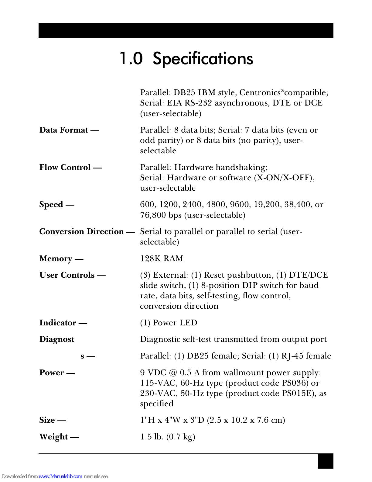
Interface —
Parallel: DB25 IBM style, Centronics®compatible;
Serial: EIA RS-232 asynchronous, DTE or DCE
(user-selectable)
Data Format —
Parallel: 8 data bits; Serial: 7 data bits (even or
odd parity) or 8 data bits (no parity), user-
selectable
Flow Control —
Parallel: Hardware handshaking;
Serial: Hardware or software (X-ON/X-OFF),
user-selectable
Speed —
600, 1200, 2400, 4800, 9600, 19,200, 38,400, or
76,800 bps (user-selectable)
Conversion Direction —
Serial to parallel or parallel to serial (user-
selectable)
Memory —
128K RAM
User Controls —
(3) External: (1) Reset pushbutton, (1) DTE/DCE
slide switch, (1) 8-position DIP switch for baud
rate, data bits, self-testing, flow control,
conversion direction
Indicator —
(1) Power LED
Diagnostic —
Diagnostic self-test transmitted from output port
Connectors —
Parallel: (1) DB25 female; Serial: (1) RJ-45 female
Power —
9 VDC @ 0.5 A from wallmount power supply:
115-VAC, 60-Hz type (product code PS036) or
230-VAC, 50-Hz type (product code PS015E), as
specified
Size —
1"H x 4"W x 3"D (2.5 x 10.2 x 7.6 cm)
Weight —
1.5 lb. (0.7 kg)
1.0 Specifications
Page 6
2
S↔P (SERIAL↔PARALLEL) CONVERTER (128K)
The S↔P (Serial↔Parallel) Converter (128K) is a serial-to-parallel or
parallel-to-serial converter (conversion direction is user-selectable). It
operates at speeds ranging from 600 bps all the way up to 76.8 Kbps and
has 128K of buffer memory, which is ideal for most ordinary print jobs and
other types of file transfers.
The Converter supports a wide variety of baud rates, three types of data
formats, and either hardware or software (X-ON/X-OFF) flow control, so it
works with many kinds of equipment and applications. You can quickly
and easily choose the settings you want with an external DIP switch. This
switch also has positions that allow you to select the conversion direction
and a self-testing mode. You can choose whether the Converter functions
as DTE or as DCE by moving an external slide switch. And by pushing an
external, recessed pushbutton, you can reset the Converter if anything goes
wrong.
The S↔P Converter’s parallel port has a DB25 female connector. Its
serial port has an RJ-45 female connector, so from there to your serial
device you can run unshielded twisted-pair cable with RJ-45 male
connectors. Modular adapters are available to complete the UTP
connection to your serial device if its serial port isn’t RJ-45.
The Converter has its own power supply, so it won’t draw power from the
devices it connects. All the energy in the communication lines goes toward
sustaining communications.
Using the Converter’s self-test mode, you can verify that your Converter
is working properly and that its cable links to your devices are intact before
any operation.
You can use two S↔P Converters in series as parallel distance extenders
by setting the first for parallel-to-serial conversion and the second for serial-
to-parallel. This will increase maximum one-way parallel transmission
distance from 20 feet (6.1 m) to as much as 540 feet (164.6 m).
2.0 Introduction
Page 7
3
CHAPTER 3: Installation
3.1 What You’ll Need
Before you attach any cables or turn anything on, make sure you have
everything necessary to set up your S↔P Converter (128K) system.
Each S↔P Converter comes with its own power supply and a 6-foot
(1.8-m) flat satin cable with RJ-45 male connectors. This cable can connect
the Converter to an RJ-45 serial port—or to a modular adapter attached to
a different type of serial port—on a nearby device.
What other equipment is necessary depends on whether you’re using a
single Converter
for parallel-to-serial conversion or serial-to-parallel
conversion (see the list in
Section 3.1.1
)ora
pair of Converters
as parallel
distance extenders (see the list in
Section 3.1.2
).
3.1.1 A
DDITIONALEQUIPMENTNECESSARY TO ASINGLE-CONVERTERSYSTEM
:
A.
One parallel cable
.
For
parallel-to-serial conversion:
Cable running from the Converter to a
PC’s parallel port should be fully pinned straight-through DB25-male-to-
DB25-male extension cable, up to 20 feet (6.1 m) long, that does
not
have
Pin 1 tied to the shield. Our product code for this cable is ECN25C.
For
serial-to-parallel conversion:
Cable running to a printer’s parallel
port should be standard IBM®parallel printer adapter cable. Our product
code for this cable is EYN600.
B. If the Converter is within 6 feet (1.8 m) of the serial port you need to
connect, you can use the flat satin cable that came with your unit.
Otherwise, you’ll need
one serial cable
.
Cable running from the Converter to the serial port of a device that’s
between 6 feet (1.8 m) and 50 feet (15.2 m) away should be RJ-45-male-to-
RJ-45-male unshielded twisted-pair (
not
flat satin!). Our product code for
this cable is EYN730MS-MM. If you need to connect a serial port further
away than 50 feet (15.2 m), contact us for extended distance data cable
(“EDDC”), one or more modular adapters, and the maximum cable length
you can run (this will depend on the speed of your serial device).
3.0 Installation
Page 8
4
S↔P (SERIAL↔PARALLEL) CONVERTER (128K)
Pinning
DB25 to RJ-45
2 -------------------------------------------------------------- 5
3 -------------------------------------------------------------- 6
5, 6, 8 ------------------------------------------------------- 3
7 -------------------------------------------------------------- 4
9 -------------------------------------------------------------- 8
20 ------------------------------------------------------------ 7
(For more detail, see the Appendix)
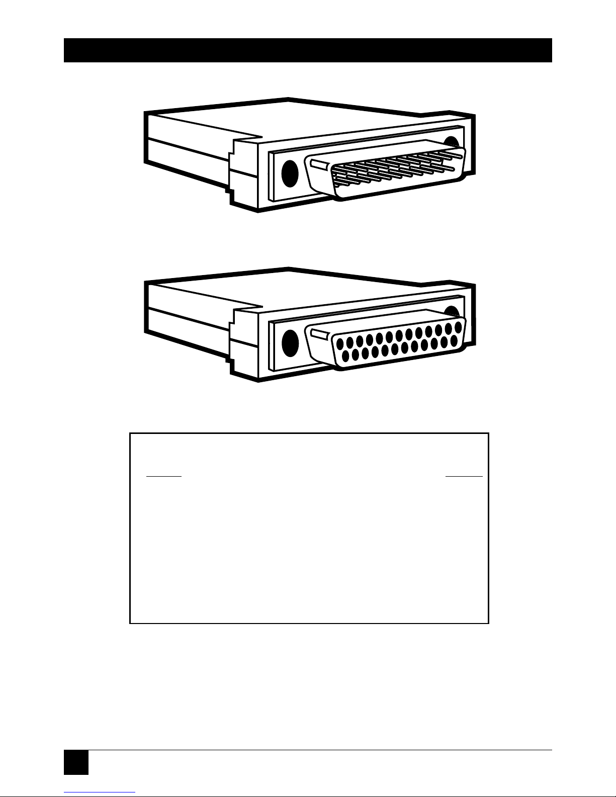
Figure 3-1. DB25 Male and Female Adapters and
Required Pinning.
FA080-R2 (Male)
FA081-R2 (Female)
Page 9

5
CHAPTER 3: Installation
C. If the serial port you need to connect is not an RJ-45 female, you will
also need
one modular adapter
.
For
parallel-to-serial
conversion: To connect RJ-45 UTP to a printer’s
serial port, use an RJ-45-female-to-DB25-male adapter pinned as in
Figure 3-1. Our product code for this adapter is FA080-R2. Refer to
Figure 3-3 for a typical system setup using this adapter.
For
serial-to-parallel
conversion: To connect RJ-45 UTP to an IBM
PC/XT™ type computer’s serial port, use an RJ-45-female-to-DB25-female
adapter pinned as in Figure 3-1. Our product code for this adapter is
FA081-R2. To connect RJ-45 UTP to an IBM AT®type computer’s serial
port, use an RJ-45-female-to-DB9-female adapter pinned as in Figure 3-2.
Our product code for this adapter is FA082-R2. Refer to Figure 3-3 for
typical system setups using these adapters.
Pinning
DB9 to RJ-45
1, 6, 8 ------------------------------------------------------- 3
2 -------------------------------------------------------------- 6
3 -------------------------------------------------------------- 5
4 -------------------------------------------------------------- 7
5 -------------------------------------------------------------- 4
(For more detail, see the Appendix)
FA082-R2
Figure 3-2. DB9 Female Adapter and Required Pinning.
Page 10

6
S↔P (SERIAL↔PARALLEL) CONVERTER (128K)
PC
Up To 20 Ft.
(ECN25C)
Up To 50 Ft.
(EYN730MS-MM)
FROM
PARALLEL
PORT
SERIAL↔PARALLEL
CONVERTER (128K)
(PI035A*)
POWER SUPPLY
(PS035A)
SERIAL PRINTER
RJ-45 TO DB25
MALE ADAPTER
(FA080)
SIGNAL DIRECTION
PC
Up To 20 Ft.
(EYN600)
Up To 50 Ft.
(EYN730MS-MM)
SERIAL↔PARALLEL
CONVERTER (128K)
(PI035A*)
POWER SUPPLY
(PS035A)
PARALLEL PRINTER
RJ-45 TO DB25
MALE ADAPTER
(FA081)
FROM SERIAL PORT
SIGNAL DIRECTION
AT
Up To 20 Ft.
(EYN600)
Up To 50 Ft.
(EYN730MS-MM)
SERIAL↔PARALLEL
CONVERTER (128K)
(PI035A*)
POWER SUPPLY
(PS035A)
PARALLEL PRINTER
RJ-45 TO DB9
FEMALE ADAPTER
(FA082)
FROM SERIAL PORT
SIGNAL DIRECTION
Figure 3-3. Typical Setups for Each of the Three Adapters.
*NOTE: 230-VAC version is product code PI035AE. 230-VAC power supply is PS015E.
®
(FA080-R2)
(FA081-R2)
FROM SERIAL PORT
Up to 20 ft. (6.1 m)
(ECN25C)
Up to 20 ft. (6.1 m)
(EYN600)
Up to 20 ft. (6.1 m)
(EYN600)
Up to 50 ft. (15.2 m)
(EYN730MS-MM)
Up to 50 ft. (15.2 m)
(EYN730MS-MM)
Up to 50 ft. (15.2 m)
(EYN730MS-MM)
(FA082-R2)
FROM SERIAL PORT
(PS036*)
(PS036*)
(PS036*)
Page 11

7
CHAPTER 3: Installation
3.1.2 A
DDITIONALEQUIPMENTNECESSARY TO ACONVERTER-PAIRSYSTEM
:
A.
One parallel input cable
.
Cable running from one Converter to a PC’s parallel port should be
fully pinned straight-through DB25-male-to-DB25-male extension cable, up
to 20 feet (6.1 m) long, that does
not
have Pin 1 tied to the shield. Our
product code for this cable is ECN25C.
B.
One parallel output cable
.
Cable running from the other Converter to a printer’s parallel port
should be standard IBM PC parallel printer adapter cable up to 20 feet
(6.1 m) long. Our product code for this cable is EYN600.
C. If your Converters are 6 feet (1.8 m) or less away from each other,
cable running between them can be one of the flat satin cables that came
with your units. Otherwise, you’ll need
one serial cable
.
If the Converters are from 6 feet (1.8 m) to 50 feet (15.2 m) apart,
cable running between them should be RJ-45-male-to-RJ-45-male
unshielded twisted-pair (
not
flat satin!). Our product code for this cable is
EYN730MS-MM.
If the Converters are from 50 feet (15.2 m) to 500 feet (152.4 m)
apart, cable running between them should be DB25-male-to-DB25-male
extended distance data cable (“EDDC”). Our product code for this cable is
PC
Up To 20 Ft.
(ECN25C)
Up To 50 Ft.
(EYN730MS-MM)
FROM
PARALLEL
PORT
SERIAL↔PARALLEL
CONVERTER (128K)
(PI035A*)
POWER
SUPPLY
(PS035A)
PARALLEL PRINTER
Up To 20 Ft.
(EYN600)
SERIAL
↔
PARALLEL
CONVERTER (128K)
(PI035A*)
Figure 3-4. A Pair of Converters Used As
Parallel Distance Extenders.
*NOTE: 230-VAC version is product code PI035AE. 230-VAC Power supply is PS015E.
SIGNAL DIRECTION
Up to 20 ft. (6.1 m)
(ECN25C)
Up to 20 ft. (6.1 m)
(EYN600)
Up to 50 ft. (15.2 m)
(EYN730MS-MM)
(PS036*)
Page 12

8
S↔P (SERIAL↔PARALLEL) CONVERTER (128K)
EDN25C. Two DB25-female-to-RJ-45-female adapters pinned as in
Figure 3-1 should be connected to the EDDC, one at each end. Our
product code for these adapters is FA081-R2. Cable running from the
Converters’ serial ports to these modular adapters could be the two flat
satin cables that came with your units. If your system consistently garbles
transmissions or loses data, however, you might have to replace the flat
satin with two short lengths of modular UTP (the cable specified in the
previous paragraph).
3.2 Installation Procedures
To complete the installation of your S↔P Converter (128K) system, follow
the steps listed in
Section 3.2.1
if you’re using a single Converter or those
listed in
Section 3.2.2
if you’re using a pair of Converters as parallel
distance extenders.
3.2.1 S
INGLE-CONVERTERPROCEDURES
1. First locate your S↔P Converter within 20 feet (6.1 m) of your parallel
device, close to a power outlet.
2. Run your parallel cable from the parallel device to the Converter’s
parallel (DB25 female) port.
3. Run UTP or the included flat satin serial cable from the S↔P
Converter’s serial (RJ-45 female) port to the RJ-45 female serial port on:
• your serial device (if it has one),
• the appropriate adapter for a serial device that has a different type of
serial port (see Figure 3-3), or
• an RJ-45-female-to-DB25-female adapter pinned as in Figure 3-1
(FA081-R2) to convert to EDDC for a long cable run.
3A. If you haven’t already, complete the link from the Converter to your
serial device:
• If you’re running flat satin/UTP, plug the adapter into the device’s
serial port.
Page 13

9
CHAPTER 3: Installation
• If you’re running EDDC, attach the EDDC to the Converter-end
adapter and run it to your serial device. Attach its free end to the DB25
female serial port on the device or to the DB25 female connector on a
second adapter. Attach any additional cable or adapters needed at the
device end.
4. Now you’re ready to set the switches on your S↔P Converter (128K).
First set its external DTE/DCE slide switch. For the great majority of appli-
cations, this switch should be set to DCE (towards the RJ connector). Only
select DTE (switch towards the parallel connector) if your serial device is
DCE (communications equipment). For example, choose DTE if remote
users will be calling in over a modem to reach a parallel printer.
Set the Converter’s DIP switch (see Table 3-1 on the next page) for the
baud rate, data bits, and flow control settings that match those of your serial
device. (Positions are ON when down and OFF when up.) Set position 6 to
ON for the self-test mode. Set position 8 to OFF if the conversion direction
is serial to parallel or set it to ON if the direction is parallel to serial.
5. Test your setup. Make sure the output device is plugged in and
turned on, then plug in the Converter. If its DIP switch posistion 6 is ON,
the Converter will perform a diagnostic self-test and send the results to the
output device. Data sent includes the name of the Converter, the settings of
its switches, and verification of a proper cable link with its output port.
After this point the unit performs a continuous “barber pole” test, which
you can watch as it scrolls on your output device’s printout or screen. If
something seems to be wrong, see
Chapter 5: Troubleshooting
. If you’re
satisfied that the system is working properly, go on to Step 6.
6. Reset the Converter. Either (1) unplug it, set DIP switch position 6 to
OFF, and plug it back in, or (2) set position 6 to OFF while it’s still plugged
in and then hit the reset button.
7. Make sure the input device is plugged in and turned on. Your S↔P
Converter (128K) system is now ready for continuous operation.
Page 14

10
S↔P (SERIAL↔PARALLEL) CONVERTER (128K)
Option Switch Position*
1234567 8
Baud Rate
76800 OFF OFF OFF
38400 ON OFF OFF
19200 OFF ON OFF
9600 ON ON OFF
4800 OFF OFF ON
2400 ON OFF ON
1200 OFF ON ON
600 ON ON ON
Data Bits/Parity
8, no parity OFF OFF
or
ON OFF
7, odd parity OFF ON
7, even parity ON ON
Self-Test
Normal Operation OFF
Self-Test ON
Flow Control
Hardware OFF
X-ON/X-OFF ON
Direction
Serial to Parallel OFF
Parallel to Serial ON
*Positions are ON when down and OFF when up.
Table 3-1. DIP Switch Settings for
S↔P (Serial↔Parallel) Converter (128K)
Page 15

11
CHAPTER 3: Installation
3.2.2 C
ONVERTER-PAIRPROCEDURES
1. First locate each Converter within 20 feet (6.1 m) of its associated
parallel device, close to a power outlet.
2. Run your parallel input cable from the PC (or whatever device is
transmitting) to the input-side Converter’s parallel (DB25 female) port.
3. Run UTP or the included flat satin serial cable from the input-side
Converter’s serial (RJ-45 female) port to the RJ-45 female serial port on:
• the output-side S↔P Converter, or
• an RJ-45-female-to-DB25-female adapter pinned as in Figure 3-1
(FA081-R2) to convert to EDDC for a long cable run.
3A. If you’re running EDDC, complete the link between the Converters.
Run the EDDC, attach the output-side FA081-R2 adapter, and run the
second length of UTP or flat satin.
4. Finish your cabling installation by running your parallel ouput cable
from the output-side Converter to the parallel printer (or whatever device
is receiving).
5. Now you’re ready to set the switches on your S↔P Converters (128K).
First set their external DTE/DCE slide switches to complement each other:
one as DCE (switch towards the RJ connector) and the other as DTE (switch
towards the parallel connector; it doesn’t matter which Converter gets
which setting). Then set their DIP switches (see Table 3-1; positions are
ON when down and OFF when up).
Set positions 1 through 5 and 7 identically: Whichever settings you
choose for one Converter should be the same on the other. It won’t make
much difference whether you choose hardware or software flow control.
We recommend 9600 baud for distances up to 500 feet (152.4 m), but if you
don’t need to transmit that far, you may be able to use higher speeds;
contact your dealer for assistance in determining your maximum baud rate.
Finally, using 8 bits with no parity will give you slightly higher throughput
than 7-bit word structures.
Page 16

12
S↔P (SERIAL↔PARALLEL) CONVERTER (128K)
Set DIP switch position 8 to ON (parallel to serial conversion) on the S↔P
Converter connected to the input (transmitting) device and to OFF (serial
to parallel conversion) on the Converter connected to the output (receiving)
device. Set switch position 6 to ON for self-test mode on the output-side
Converter and to OFF for normal operation on the input-side unit (setting
both to ON at the same time might yield misleading self-test results).
6. Test your setup. Make sure the output device is plugged in and
turned on, then plug in the output-side Converter. It will perform a
diagnostic self-test and send the results to the output device. Data sent
includes the name of the Converter, the settings of its switches, and
verification of a proper cable link with its output port. After this point the
unit performs a continuous “barber pole” test, which you can watch as it
scrolls on your output device’s printout or screen. If something seems to be
wrong, see
Chapter 5: Troubleshooting
. If you’re satisfied that the output
side of the system is working properly, go to Step 7.
7. Unplug both Converters, reverse the settings of switch position 6 on
both units, replug the output-side Converter and then the input-side one.
Observe the input-side unit’s self-test. If something doesn’t seem right, see
Chapter 5
. Otherwise, go to Step 8.
8. Reset the input-side Converter. Either (1) unplug it, set DIP-switch
position 6 to OFF, and plug it back in, or (2) set position 6 to OFF while it’s
still plugged in and then hit the reset button.
9. Make sure the input device is plugged in and turned on. Your S÷P
Converter (128K) system is now ready for continuous operation.
Page 17

13
CHAPTER 4: Operation
Once you’ve installed the S↔P Converter (128K), run a few test
transmissions. If one or more don’t get through intact, see
Chapter 5:
Troubleshooting
.
If at any time something goes wrong with a transmission, you can press
the Reset button to reset the Converter without having to unplug it or
restart your devices. Also see
Chapter 5
for troubleshooting suggestions.
After the Converter is up and working properly, few adjustments should
be necessary. Every so often, especially (1) at system boot time if your
system is powered down frequently or (2) any time your system performance
seems to deteriorate, you might want to set the Converter to perform its
self-test (DIP switch position 6 to ON). The self-test could reveal, or make it
easier to diagnose, a problem. If a problem does become evident, see
Chapter 5
.
Any time you upgrade or replace a serial device connected to your S↔P
Converter, reposition the Converter’s baud-rate, word-structure, flow-
control, and DTE/DCE switches as necessary.
4.0 Operation
Page 18

14
S↔P (SERIAL↔PARALLEL) CONVERTER (128K)
5.1 Common Concerns
This section lists some problems that might come up during installation or
operation of the S↔P Converter (128K), along with some solutions.
5.1.1 THEC
ONVERTER’SPOWER
LED D
OESN’TLIGHTUP
1. Make sure the Converter’s power supply is firmly mounted in the
outlet. If it is, go to Step 2.
2. Try a different outlet, or test the outlet you have been attempting to
use by plugging another device into it. If the outlet isn’t supplying power,
it might have to be repaired before you can use it.
3. If the problem isn’t solved, the power supply might be bad. If you
have another power supply that supplies the same voltage and has a
compatible type of output plug, try replacing the original.
4. If the problem still isn’t solved, call us.
5.1.2 THEC
ONVERTER’SPOWER
LED L
IGHTSUP
, B
UT ATRANSMISSIONWAS
G
ARBLED ORDIDN’TGETTHROUGHATALL
or
IP
RESSED THERESETBUTTONBUTNOTHINGHAPPENED
A. Single-Converter Systems Only:
1. Make sure the attached devices are plugged in and turned on. If
they are, go to Step 2.
2. Make sure all of your cables are firmly seated at both ends. Make
sure any adapter you have plugged directly into a device’s serial port is also
firmly seated. If all cable and adapter connections are solid, go to Step 3.
3. The transmitting device or its software might have crashed. If the
transmitting device and its application appear to be functioning normally,
go to Step 4.
5.0 Troubleshooting
Page 19

15
4. Check the Converter’s DTE/DCE slide switch and the word-
structure and flow-control settings of its DIP switch. If they are correctly set
for communication with your serial device, go to Step 5.
5. A cable run may be too long. Cable length for parallel communica-
tion must not exceed 20 feet (6.1 m) between any pair of devices; serial
cable length must not exceed 50 feet (15.2 m) for UTP or 500 feet (152.4 m)
for extended distance data cable. If either of your devices is too far from
the S↔P Converter, move the Converter or move the device.
6. If the problem isn’t solved, run the Converter’s self-test by setting
its DIP switch position 6 to ON. If the self-test data is not transmitted
properly to the output device, you can concentrate on the ouput device and
cable as you search for the cause of the problem. If the data is transmitted
properly, you can concentrate on the input device, its software, and the
input cable. go to Step 7.
7. A cable might be broken. Visually inspect the length of your cables
or continuity-test them. You can also try replacing the cable with identical
cable you know is OK.
8. If the problem isn’t solved, a cable or an adapter may be pinned
incorrectly. Any parallel cable connecting the parallel ports of your
Converter and a PC (RS-232 extension cable), as well as any UTP or EDDC
serial cable, should be pinned straight-through. This means that a single
wire connects Pin 1 at one end to Pin 1 at the other end. Likewise Pin 2 is
wired to Pin 2, 3 to 3, and so on. Also, the RS-232 extension cable must not
have Pin 1 tied to the shield.
If you’re using an adapter compatible with one of those shown in
Figures 3-1 and 3-2, compare the pinning in the charts in Figure 3-1 or 3-2
and in the Appendix with the pinning listed in your adapter’s
documentation (do
not
disassemble the adapter). If you’re unable to
determine the pinning of your adapter, or if you’re using an adapter with a
different type of connector, call us.
9. If the problem isn’t solved, check the hardware and software
configurations of the attached devices. If possible, test both of your devices
by detaching them from the S↔P Converter and connecting them to
different equipment (serial device to serial device, parallel device to parallel
device). Attempt communication through the same serial or parallel port
you were using when the problem occurred. If possible, use the same serial
CHAPTER 5: Troubleshooting
Page 20

16
S↔P (SERIAL↔PARALLEL) CONVERTER (128K)
or parallel cable, or an identical cable you know is OK. If communication
goes smoothly for both of your devices and their associated cables when the
Converter isn’t involved, go to Step 10.
If there is still a problem after you make these substitutions, any of
several device-related difficulties may be occurring. Some examples:
• One of the attached devices might be set up to communicate
through the wrong port.
• One of the device ports is broken.
• One of the attached devices or its software may be hitting a fault
(a bug in its programming) when it tries to communicate.
• A software package or a driver on one device might be incompatible
with the other device.
The problem could also be highly application-specific. For example,
the polarity option on HP®LaserJet®printers is often set incorrectly. You
might want to consult the manuals of the devices and software involved in
the problem as you carefully investigate your application.
10. If the problem still isn’t solved, call us.
B. Converter-Pair (Parallel Distance Extension) Systems Only
1. Make sure the attached devices are plugged in and turned on. If
they are, go to Step 2.
2. Make sure all of your cables are firmly seated at both ends. If all
cable connections are solid, go to Step 3.
3. The transmitting device or its software might have crashed. If the
transmitting device and its application appear to be functioning normally,
go to Step 4.
4. Check the Converters’ DTE/DCE slide switches and the word-
structure and flow-control settings of their DIP switches. If they are
correctly set for communication with each other (see
Section 3.2.2, Step 5
),
go to Step 5.
Page 21

17
5. A cable run may be too long. Cable length for parallel communica-
tion must not exceed 20 feet (6.1 m) between any pair of devices; serial
cable length must not exceed 50 feet (15.2 m) for UTP or 500 feet (152.4 m)
for extended distance data cable. If either of your devices is too far from
the S↔P Converter it’s directly attached to, move the Converter or move
the device. If your Converters are too far from each other, move one of
them and, if necessary, its attached device.
6. If the problem isn’t solved, run the self-test on the output-side
Converter by setting its DIP switch position 6 to ON. If the self-test data is
not transmitted properly to the output device, you can concentrate on the
ouput device and cable as you search for the cause of the problem—turn
the self-test off and go to Step 8. If the data is transmitted properly, go to
Step 7.
7. Reverse the settings of position 6 on the two Converters, so that the
one on the output side is back to normal operation and the one on the
input side runs the self test. If the input-side self-test data is transmitted
properly, you can concentrate on the input device, its software, and the
input cable as you search for the cause of the problem. If the data is not
transmitted properly, you can concentrate on the cable and any adapters
between the Converters. Turn the self-test off and go to Step 8.
8. A cable might have come loose. If all cables are firmly seated, go to
Step 9.
9. A cable might be broken. Visually inspect the length of your cables
or continuity-test them. You can also try replacing the cable with identical
cable you know is OK.
10. If the problem isn’t solved, a cable or an adapter may be pinned
incorrectly. Any parallel cable connecting the parallel ports of your
Converter and a PC (RS-232 extension cable), as well as any UTP or EDDC
serial cable, should be pinned straight-through. This means that a single
wire connects Pin 1 at one end to Pin 1 at the other end. Likewise Pin 2 is
wired to Pin 2, 3 to 3, and so on. Also, the RS-232 extension cable must not
have Pin 1 tied to the shield.
If you’re using a pair of adapters with EDDC, compare the FA081-R2
adapter pinning listed in Figure 3-1 and in the Appendix with the pinning
listed in your adapter’s documentation (do
not
disassemble the adapter). If
you’re unable to determine the pinning of your adapter, or if you’re using
an adapter with a different type of connector, call us.
CHAPTER 5: Troubleshooting
Page 22

18
S↔P (SERIAL↔PARALLEL) CONVERTER (128K)
11. If the problem isn’t solved, check the hardware and software
configurations of the attached devices. If possible, test both of your devices
by detaching them from the S↔P Converter and connecting them to each
other with your input or output cable. Attempt communication through
the same parallel ports you were using when the problem occurred. If
communication goes smoothly for both of your devices and their associated
cables when the Converter isn’t involved, go to Step 12.
If there is still a problem after you make these substitutions, any of
several device-related difficulties may be occurring. Some examples:
• One of the attached devices might be set up to communicate
through the wrong port.
• One of the parallel ports you are using is broken.
• One of the attached devices or its software may be hitting a fault
(a bug in its programming) when it tries to communicate.
• A software package or a driver on one device might be incompatible
with the other device.
The problem could also be highly application-specific. For example,
the polarity option on HP LaserJet printers is often set incorrectly. You
might want to consult the manuals of the devices and software involved in
the problem as you carefully investigate your application.
12. If the problem still isn’t solved, call us.
5.1.3 I’
MLOSINGDATA
1. Check the word-structure and flow-control settings of the Converter’s
DIP switch. If they are correctly set to match your serial device, go to
Step 2.
2. The transmission may have overflowed the buffer. There’s a very
good chance of this if you are sending files with lots of graphics. Try
breaking such files into smaller pieces.
3. If the problem isn’t solved, call us.
Page 23

19
CHAPTER 5: Troubleshooting
5.2 Calling Us
If your Serial↔Parallel Converter (128K) seems to be malfunctioning,
do not
attempt to alter or repair the unit.
Contact us; the problem might be solvable
over the phone.
Before you do, make a record of the history of the problem. We’ll be able
to provide more efficient and accurate assistance if you have a complete
description, including:
• the nature and duration of the problem
• when the problem occurs
• the components involved in the problem
• any particular application that, when used, appears to create the
problem or make it worse
5.3 Shipping and Packaging
If you need to transport or ship your Serial↔Parallel Converter (128K):
• Carefully package the Converter. We recommend that you use the
original container.
• If you are shipping the Converter for return or repair, make sure you
include its power supply and this manual. Before you ship, contact
your supplier to get a Return Materials Authorization (RMA) number.
Page 24

A.1 Serial Connectors of Converter and Adapters
The first column shows the pinning of the S↔P Converter’s RJ-45
connector, the second column shows the pinning of the DB25 connectors of
the FA080-R2 and FA081-R2 adapters, and the third column shows the
pinning of the FA082-R2 adapter’s DB9 connector. Straight-through-
pinned RJ-45 cable must be run between the Converter and any of these
adapters. This pinout is not affected by whether the Converter is set for
serial-to-parallel or parallel-to-serial operation.
Pin Numbers Signal Function Direction, Converter set as:
RJ-45 DB25 DB9 DCE DTE
3 5 1 CTS Flow Control From Converter To Converter
6 6 DSR
88 CD
4 7 5 SGD Signal Ground
5 2 3 RXD Receive Data To Converter From Converter
6 3 2 TXD Transmit Data From Converter To Converter
7 20 4 DTR Flow Control To Converter From Converter
8 9 +10V Steady Positive
Voltage
20
S↔P (SERIAL↔PARALLEL) CONVERTER (128K)
Appendix: Connector Pinouts
Page 25

21
APPENDIX: Connector Pinouts
A.2 The Converter’s Parallel Connector
This pinout is not affected by whether the Converter is set as DCE or DTE.
Pin No. Function Direction, Converter set for:
Serial to Parallel* Parallel to Serial
1 Strobe From Converter To Converter
2 Data Bit 1 From Converter To Converter
3 Data Bit 2 From Converter To Converter
4 Data Bit 3 From Converter To Converter
5 Data Bit 4 From Converter To Converter
6 Data Bit 5 From Converter To Converter
7 Data Bit 6 From Converter To Converter
8 Data Bit 7 From Converter To Converter
9 Data Bit 8 From Converter To Converter
10 Acknowledge To Converter From Converter
11 Busy To Converter From Converter
12 (Paper Empty) No Connection
13 Select Held High
14 No Connection
15 Fault Held High
16 Input Prime Held High
17 No Connection
18 Ground Ground
19 Ground Ground
20 Ground Ground
21 Ground Ground
22 Ground Ground
23 Ground Ground
24 Ground Ground
25 Ground Ground
*The strobe’s duration is 2 microseconds long in units with serial number
94010763, Version 1.2. If you have a problem with garbled data during
serial to parallel conversion, please contact us.
Page 26

NOTES
 Loading...