

Page 1
Order toll-free in the U.S.: Call 877-877-BBOX (outside U.S. call 724-746-5500)
FREE technical support 24 hours a day, 7 days a week: Call 724-746-5500 or fax 724-746-0746
Mailing address: Black Box Corporation, 1000 Park Drive, Lawrence, PA 15055-1018
Web site: www.blackbox.com • E-mail: info@blackbox.com
CUSTOMER
SUPPORT
INFORMATION
JULY 1992
PCM90A
PCM91
PCM82-C
PCM83-C
PCM84-C
LinkUp 5294
DL5294 Firmware
5294
P
U
INK
L
RESET
CHANNEL/ERROR
IO FLT
RXC
TXC
RI/
CD
SYN
DSR
DTR
CTS
RTS
RXD
TXD
DTE
DCE
SYS
ON
CK
CH SEL
Page 2

LINKUP 5294 WITH DL5294 FIRMWARE
1
FEDERAL COMMUNICATIONS COMMISSION
AND
INDUSTRY CANADA
RADIO FREQUENCY INTERFERENCE STATEMENTS
This equipment generates, uses, and can radiate radio-frequency energy, and if not installed and used
properly, that is, in strict accordance with the manufacturer’s instructions, may cause interference to radio
communication. It has been tested and found to comply with the limits for a Class A computing device in
accordance with the specifications in Subpart B of Part 15 of FCC rules, which are designed to provide
reasonable protection against such interference when the equipment is operated in a commercial
environment. Operation of this equipment in a residential area is likely to cause interference, in which
case the user at his own expense will be required to take whatever measures may be necessary to correct
the interference.
Changes or modifications not expressly approved by the party responsible for compliance could void the user’s
authority to operate the equipment.
This digital apparatus does not exceed the Class A limits for radio noise emission from digital apparatus set out in the Radio
Interference Regulation of Industry Canada.
Le présent appareil numérique n’émet pas de bruits radioélectriques dépassant les limites applicables aux appareils numériques
de la classe A prescrites dans le Règlement sur le brouillage radioélectrique publié par Industrie Canada.
Page 3

LINKUP 5294 WITH DL5294 FIRMWARE
2
INSTRUCCIONES DE SEGURIDAD (Normas Oficiales Mexicanas Electrical Safety Statement)
1. Todas las instrucciones de seguridad y operación deberán ser leídas antes de que el aparato eléctrico sea operado.
2. Las instrucciones de seguridad y operación deberán ser guardadas para referencia futura.
3. Todas las advertencias en el aparato eléctrico y en sus instrucciones de operación deben ser respetadas.
4. Todas las instrucciones de operación y uso deben ser seguidas.
5. El aparato eléctrico no deberá ser usado cerca del agua—por ejemplo, cerca de la tina de baño, lavabo, sótano
mojado o cerca de una alberca, etc..
6. El aparato eléctrico debe ser usado únicamente con carritos o pedestales que sean recomendados por el fabricante.
7. El aparato eléctrico debe ser montado a la pared o al techo sólo como sea recomendado por el fabricante.
8. Servicio—El usuario no debe intentar dar servicio al equipo eléctrico más allá a lo descrito en las instrucciones de
operación. Todo otro servicio deberá ser referido a personal de servicio calificado.
9. El aparato eléctrico debe ser situado de tal manera que su posición no interfiera su uso. La colocación del aparato
eléctrico sobre una cama, sofá, alfombra o superficie similar puede bloquea la ventilación, no se debe colocar en
libreros o gabinetes que impidan el flujo de aire por los orificios de ventilación.
10. El equipo eléctrico deber ser situado fuera del alcance de fuentes de calor como radiadores, registros de calor, estufas
u otros aparatos (incluyendo amplificadores) que producen calor.
11. El aparato eléctrico deberá ser connectado a una fuente de poder sólo del tipo descrito en el instructivo de
operación, o como se indique en el aparato.
12. Precaución debe ser tomada de tal manera que la tierra fisica y la polarización del equipo no sea eliminada.
13. Los cables de la fuente de poder deben ser guiados de tal manera que no sean pisados ni pellizcados por objetos
colocados sobre o contra ellos, poniendo particular atención a los contactos y receptáculos donde salen del aparato.
14. El equipo eléctrico debe ser limpiado únicamente de acuerdo a las recomendaciones del fabricante.
15. En caso de existir, una antena externa deberá ser localizada lejos de las lineas de energia.
16. El cable de corriente deberá ser desconectado del cuando el equipo no sea usado por un largo periodo de tiempo.
17. Cuidado debe ser tomado de tal manera que objectos liquidos no sean derramados sobre la cubierta u orificios de
ventilación.
18. Servicio por personal calificado deberá ser provisto cuando:
A: El cable de poder o el contacto ha sido dañado; u
B: Objectos han caído o líquido ha sido derramado dentro del aparato; o
C: El aparato ha sido expuesto a la lluvia; o
D: El aparato parece no operar normalmente o muestra un cambio en su desempeño; o
E: El aparato ha sido tirado o su cubierta ha sido dañada.
Page 4

LINKUP 5294 WITH DL5294 FIRMWARE
3
TRADEMARKS USED IN THIS MANUAL
Apple®and Macintosh®are registered trademarks of Apple Computer, Inc.
Centronics
®
is a registered trademark of Centronics Corporation.
COMPAQ
®
is a registered trademark of Compaq Computer Corporation.
Hewlett-Packard
®
, HP®, and LaserJet®are registered trademarks of Hewlett-Packard.
IBM
®
, AS/400®, and AT®are registered trademarks of International Business Machines.
Any other trademarks mentioned in this manual are acknowledged to be the property of the trademark owners.
Page 5

LINKUP 5294 WITH DL5294 FIRMWARE
4
Contents
Chapter Page
1. Specifications .........................................................................................................................................8
2. Introduction .........................................................................................................................................9
3. Features and Applications .....................................................................................................................11
3.1 Display Emulation Support ......................................................................................................11
3.2 Printer Emulation Support.......................................................................................................15
3.3 Virtual Device Addressing ........................................................................................................18
3.4 User-Friendly Facilities..............................................................................................................20
3.5 File-Transfer Support ................................................................................................................21
3.6 Modify for 3174 Protocol..........................................................................................................22
3.7 Port Test and System Management Modes..............................................................................22
3.8 5251/5294/5394 Emulation.....................................................................................................23
3.9 Additional Features...................................................................................................................23
4. Hardware Overview................................................................................................................................24
4.1 Front Panel................................................................................................................................24
4.2 Front Panel Controls.................................................................................................................24
4.3 Channel Status Indicators ........................................................................................................25
4.4 System Status Indicators ...........................................................................................................26
4.5 Error Code Display....................................................................................................................26
4.6 Rear Panel ................................................................................................................................26
5. Electrical Characteristics .......................................................................................................................27
5.1 Power Specifications .................................................................................................................27
5.2 Cable Pin Requirements...........................................................................................................27
6. Installation .......................................................................................................................................29
6.1 Installing the LinkUp 5294 and the Configuration Terminal................................................29
6.1.1 Unpack the LinkUp 5294 ............................................................................................29
6.1.2 Install the LinkUp 5294 ...............................................................................................29
6.1.3 Set Up the Configuration Terminal ............................................................................30
6.1.4 Connect the Configuration Terminal .........................................................................30
6.1.5 Establish Communication............................................................................................30
6.1.6 Select a Device Type .....................................................................................................30
6.2 Accessing the LinkUp 5294 Configurator ...............................................................................31
6.3 Connecting Additional Local Terminals .................................................................................31
6.4 Connecting Remote Terminals ................................................................................................32
6.4.1 Line Configuration.......................................................................................................32
6.4.2 Modem Considerations................................................................................................32
Page 6

LINKUP 5294 WITH DL5294 FIRMWARE
5
Contents (continued)
Chapter Page
6.5 Connecting Printers..................................................................................................................32
6.5.1 Local Printers................................................................................................................32
6.5.2 Remote Printers............................................................................................................33
6.5.3 Auxiliary Printers..........................................................................................................33
6.6 Connecting the LinkUp 5294 to the Host Computer.............................................................34
6.6.1 Requirements................................................................................................................35
6.6.2 Dual Host Installations.................................................................................................35
6.6.3 Establish Communication with the Host ....................................................................36
7. Operation .......................................................................................................................................37
7.1 Operating Requirements..........................................................................................................37
7.1.1 Cables and Connections ..............................................................................................37
7.1.2 System/3X Host............................................................................................................38
7.1.3 ASCII Terminal .............................................................................................................38
7.1.4 Personal Computers and Terminal Emulation Software ...........................................39
7.1.5 ASCII Printer ................................................................................................................39
7.1.6 Modems.........................................................................................................................39
7.1.7 Packet Network Terminal Node ..................................................................................39
7.2 Connect Mode...........................................................................................................................40
7.2.1 Sign-On Menu...............................................................................................................40
7.2.2 Menu Prompts and Parameters...................................................................................41
7.2.3 Editing Instructions......................................................................................................44
7.2.4 Error Messages..............................................................................................................44
7.3 Port Test Mode ..........................................................................................................................45
7.3.1 Port Test Mode Menu and Functions..........................................................................46
7.4 System Management Mode ......................................................................................................47
7.4.1 System Management Mode Menu and Functions ......................................................48
7.5 Configurator Mode ...................................................................................................................54
7.5.1 Help Messages During Configuration.........................................................................54
7.5.2 Consistency Checking ..................................................................................................54
7.5.3 Overridable Parameters ...............................................................................................55
7.5.4 Configurator Mode Commands ..................................................................................55
7.5.5 Configuration Procedures ...........................................................................................59
7.5.6 Synchronous Port Parameters .....................................................................................59
7.5.7 Asynchronous Port Parameters ...................................................................................61
7.5.8 Logical Unit Parameters for a Display.........................................................................65
7.5.9 Printer Logical Unit Parameters for a Printer or Auxiliary Printer ..........................70
7.5.10 Syntax Error Messages..................................................................................................73
7.5.11 Physical Configuration .................................................................................................73
7.6 Emulation Mode .......................................................................................................................74
7.7 Setup Mode ...............................................................................................................................74
Page 7

LINKUP 5294 WITH DL5294 FIRMWARE
6
Contents (continued)
Chapter Page
8. Packet Network Access Applications.....................................................................................................76
8.1 Terminology ..............................................................................................................................76
8.2 Using the LinkUp 5294 with PDNs.........................................................................................77
8.3 Installation Considerations.......................................................................................................79
8.3.1 PAD Parameters............................................................................................................80
8.4 Special Operational Considerations ........................................................................................81
8.5 Other Special Considerations ..................................................................................................81
8.5.1 Screen Display Errors..................................................................................................81
8.5.2 Data Forwarding to the PAD........................................................................................81
9. Diagnostics .......................................................................................................................................82
9.1 On-Line Diagnostics..................................................................................................................82
9.1.1 Front-Panel Error Codes..............................................................................................82
9.1.2 Front-Panel Status Indicators.......................................................................................82
9.2 Off-Line Diagnostics .................................................................................................................85
9.2.1 Self Diagnostics.............................................................................................................85
9.2.2 LU and Port Assignment Status...................................................................................85
9.3 Finding and Identifying Problems ...........................................................................................86
10. Emulation Capabilities...........................................................................................................................89
10.1 5250 Display Emulation............................................................................................................89
10.2 5250 Keyboard Functions.........................................................................................................89
10.3 LinkUp 5294 Extended Keyboard Functions..........................................................................89
10.4 Printer Support: System vs. Local Copy...................................................................................89
11. Hardware and Software Requirements....................................................................................................93
11.1 ASCII Terminals ........................................................................................................................93
11.2 Personal Computers and Word Processors..............................................................................96
11.3 Auxiliary Attached ASCII Printers ...........................................................................................97
11.4 Asynchronous Modems.............................................................................................................99
APPENDIX A: EBCDIC/ASCII Translation Tables.....................................................................................100
APPENDIX B: IBM EBCDIC to ISO ASCII Translation Table ...................................................................117
APPENDIX C: Supported ASCII Devices.....................................................................................................118
APPENDIX D: System/36 Configuration Guide.........................................................................................122
D.1 Communications Line ............................................................................................................123
D.2 Remote Controller, Display Stations, and Printers ...............................................................128
D.3 Changing the Master Configuration Record.........................................................................133
APPENDIX E: System/38 Configuration Guide .........................................................................................136
Page 8

LINKUP 5294 WITH DL5294 FIRMWARE
7
Contents (continued)
Chapter Page
APPENDIX F: Terminal Modules and ASCII Terminal Setups ..................................................................142
F.1 ACT5A Terminal Module - Microcom ACT-5A .....................................................................143
F.2 ADM11 Terminal Module - Lear Siegler ADM-11.................................................................146
F.3 ADM21 Terminal Module - Lear Siegler ADM-21.................................................................148
F.4 ADM3A Terminal Module - Lear Siegler ADM-3A................................................................151
F.5 ADM3P Terminal Module - Lear Siegler ADM-3A Emulators..............................................154
F.6 ANSI Terminal Module - ANSI Standard 3.64.......................................................................156
F.7 COMPU Terminal Module .....................................................................................................158
F.8 C7101 Terminal Module - C. Itoh CIE 7101..........................................................................159
F.9 C7103 Terminal Module - C. Itoh CIE 7103..........................................................................162
F.10 CY5291 Terminal Module - Cybernex XLB-5291 ..................................................................165
F.11 DISPH Terminal Module - Northern Telecom Displayphone..............................................167
F.12 D200 Terminal Module - Data General Dasher 200..............................................................170
F.13 HP45 Terminal Module - Hewlett-Packard HP-2645 ............................................................173
F.14 HZ51 Terminal Module - Hazeltine 10/51............................................................................176
F.15 IQ120 Terminal Module - Soroc IQ-120 ................................................................................178
F.16 I3101 Terminal Module - IBM 3101.....................................................................................181
F.17 I3151 Terminal Module - IBM 3151.......................................................................................184
F.18 I3161 Terminal Module - IBM 3161/3163.............................................................................187
F.19 I3164 Terminal Module - IBM 3164.......................................................................................190
F.20 REBUS 3000 Terminal Module - Rebus 3000........................................................................193
F.21 SCANS Terminal Module - Tymshare Scanset.......................................................................196
F.22 TV910 Terminal Module - TeleVideo 910..............................................................................199
F.23 TV910P Terminal Module - TeleVideo 910 Plus/912 ...........................................................201
F.24 TV925 Terminal Module - TeleVideo 920/925/950 .............................................................205
F.25 TV970 Terminal Module - TeleVideo TV-970........................................................................209
F.26 VIEWP Terminal Module - ADDS Viewpoint/Regent ..........................................................212
F.27 VP60 Terminal Module - ADDS Viewpoint 60.......................................................................215
F.28 VT52 Terminal Module - DEC VT52......................................................................................218
F.29 VT52X Terminal Module - DEC VT52 Emulators.................................................................220
F.30 VT100 Terminal Module - DEC VT100..................................................................................222
F.31 VT220 Terminal Module ........................................................................................................225
F.32 WY30 Terminal Module - Wyse WY30 ....................................................................................228
F.33 WY60 Terminal Module - Wyse WY60 ....................................................................................230
F.34 WY60X Terminal Module - Wyse WY60 with Extended Keyboard .......................................230
F.35 WY100 Terminal Module - Wyse WY100 ................................................................................233
F.36 XT100 Terminal Module ........................................................................................................236
Page 9

LINKUP 5294 WITH DL5294 FIRMWARE
8
1. Specifications
Protocol — SNA/SDLC
Speed — 100 bps to 19.2 kbps; Autobaud (300–9600) standard
Emulation — Controller: IBM
®
5251 M12, 5294, and 5394
Indicators — Channel/Error display; Power monitor; System OK LED;
Channel Status LEDs: DCE, DTE, TXD, RXD, CTS, DTR, CD, TXC, RI/SYN,
RXC I/O FAULT
Interface — To host: synchronous RS-232C/V.24, DTE or DCE selectable;
To users: asynchronous RS-232C/V.24 or RS-530, DTE, DCE, or auto-selectable
Connectors —
Host: DB25 female to user’s DB25 female or DB9 male
Power — 115 or 230 VAC, switch-selectable, 50 or 60 Hz, 50 watts
Size — 6"H x 16.8"W x 11"D (15.2 x 42.7 x 27.9 cm)
Weight — 17 lb. (7.7 kg)
Page 10
CHAPTER 2: Introduction
9
2. Introduction
The LinkUp 5294 is one of the most feature-rich protocol converters on the market today. For example,
it supports the following:
• IBM PC to System/3X file transfers
• Up to 19.2K baud rate, synchronously and asynchronously
• Dual System/3X hosts
• Packet Data Network Access
• Viral Device Addressing
• Auxiliary printing
• Advanced diagnostic and system information functions
Functionally, the LinkUp is designed to convert an IBM System/3X host’s synchronous (SNA/SDLC)
protocol to asynchronous (and vice versa). It also translates the IBM host’s EBCDIC code to ASCII (and
vice versa). To accomplish these tasks, it emulates an IBM 5251 Model 12 Remote Workstation
Controller, a 5294 Remote Cluster Controller, or a 5394 Remote Cluster Controller. PU Type 1 is
implemented by the LinkUp in all emulations.
The LinkUp attaches to the sync communications adapter on your System/34/36/38 or AS/400. It can
be directly (with just an RS-232 cable) or remote (through synchronous modems).
Once you make the connections, the LinkUp enables almost any ASCII terminal or personal computer
and word processor (with the appropriate terminal-emulation software installed) to appear to the IBM
host as an actual 5251 Model 11, 5291, or 5292 Display Workstation, implemented as LU Type 7. It also
lets almost any ASCII printer to appear to the IBM host as an actual 5224, 5225, or 5256 Printer
Workstation, implemented as LU Type 4. Each of these ASCII devices can be directly or remotely
connected through asynchronous modems.
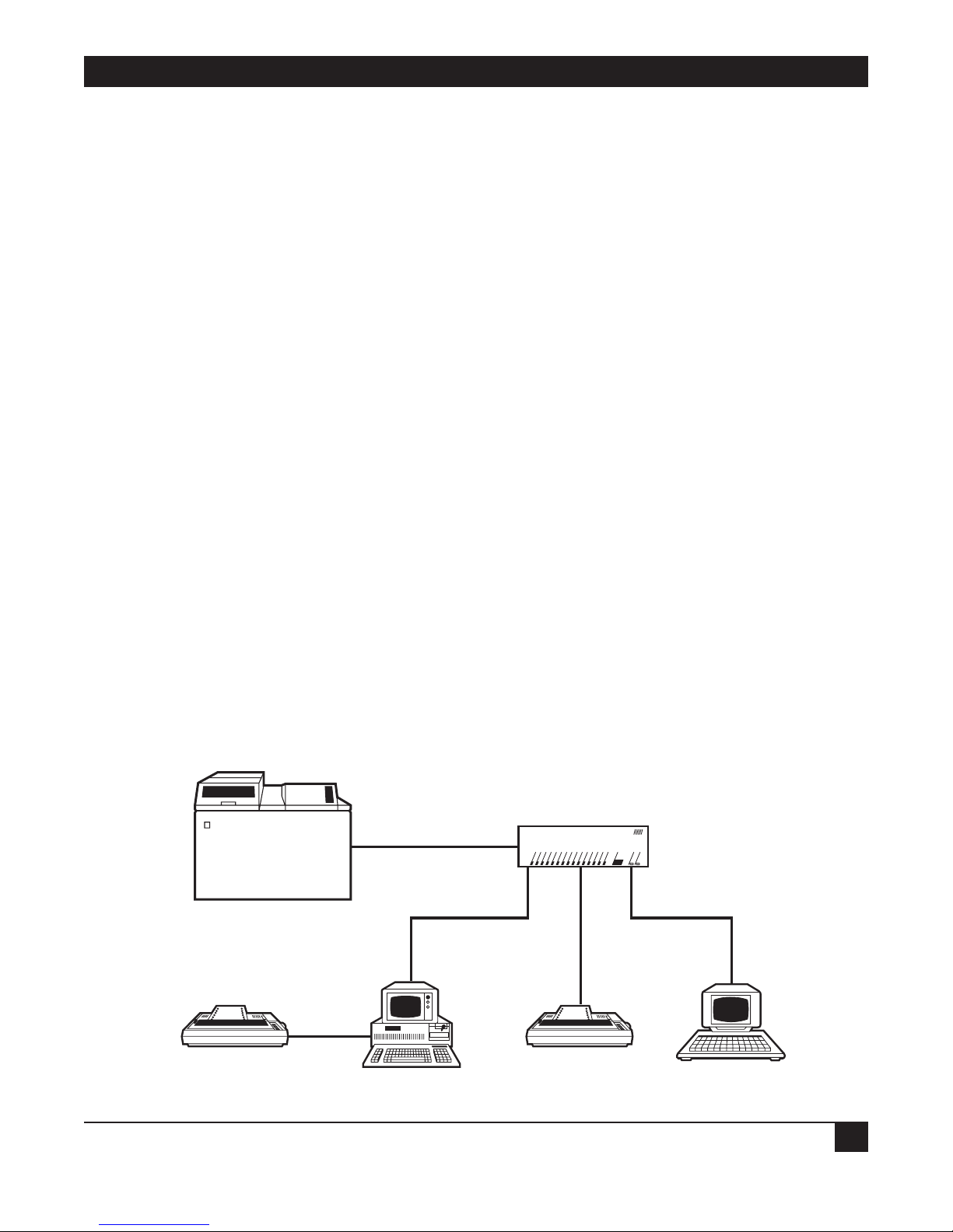
Figure 2-1 shows a typical LinkUp 5294 application.
Figure 2-1. A Typical Application of the LinkUp 5294.
LinkUp 2594
IBM SYS/36
Synchronous
RS-232 Interface
Locally or Remotely
Attached
DATALYNX/5294
ON SYS OKDCE DTE TXD RXD RTS CTS DTR DSR CD RI/SYN TXC RXC I/O FLT CHANNEL ERROR CH SEL RESET
DataLynx /5294
TM
Up to 32 Async Ports
Support Locally or
Remotely Attached
Devices
PC
ASCII PRINTERASCII PRINTER
ASCII TERMINAL
Page 11

LINKUP 5294 WITH DL5294 FIRMWARE
10
The base model is equipped with a minimum of two sync ports, and can be easily upgraded in
increments of four or eight ports, until a maximum of 34 (numbered 0 through 33) are installed. Call
your supplier to find out how to order this upgrade when you wish to expand the number of connectors
on your LinkUp unit.
NOTE
Port 0 and Port 1 support synchronous transmissions. Ports 2 through 33 support
asynchronous transmissions.
The following manuals may prove useful during the installation and operation of the LinkUp 5294.
• IBM 5250 Information Display System Functions Reference
• IBM Synchronous Data Link Control General Information
• IBM Systems Network Architecture Concepts and Products
Page 12

CHAPTER 3: Features and Applications
11
3. Features and Applications
This chapter covers the features and applications of the LinkUp 5294.
3.1 Display Emulation Support
The LinkUp 5294 enables almost any ASCII terminal or personal computer and word processor (with
the appropriate terminal emulation software installed) to appear to your System/3X host as an actual
5251 Model 11, 5291, or 5292 Display Workstation. It accomplishes this through a variety of Terminal
Modules.
A Terminal Module is a device driver which is designed after a specific ASCII terminal type, with some of
the terminal type’s unique features incorporated into the module in order to optimize its performance.
NOTE
Any terminal (or terminal emulation software) capable of simulating the terminal type of
a specific module can also be supported by that module. See Appendix D for a
complete list of the various terminals, personal computers, and word processors
currently supported by the LinkUp 5294.
Each Terminal Module has a full implementation of all of the 5250 screen handling facilities, such as
attributes and cursor positioning, and most of the keyboard functions. The specific display attributes
supported by the LinkUp include the following:
• Reverse Image
• Column Separator
• Non-display
• High-Intensity
• Blink
• Underscore
Any combination of these is also possible.
However, these facilities are supported only as well as the terminals in your application support them. In
other words, if the terminal in your application does not support one of the listed attributes, the LinkUp
5294 cannot implement that attribute for the terminal.
Another feature is Screen Optimization. Instead of clearing and repainting a terminal’s screen of data
for every new update, the LinkUp simply repaints the terminal’s screen with only the updated new
characters, keeping the amount of screen painting to a minimum.
Page 13

LINKUP 5294 WITH DL5294 FIRMWARE
12
Each of the 5250 keyboard functions supported by the LinkUp Terminal Modules has been
implemented in a manner most suited to the keyboard layout of the particular terminal that the module
is designed after. The supported 5250 functions are listed below:
CURSOR MOVEMENT
• Character Backspace
• Cursor Up
• Cursor Down
• Cursor Left
• Cursor Right
• Field Advance
• Field Backspace
• New Line
• Fast Left
• Fast Right
SPECIAL CONTROL
• Error Reset
• Insert
• Delete
• Erase Input
• Home
FIELD EXIT
• Duplicate
• Field Minus
• Field Plus
• Field Exit
SPECIAL HOST
• System Request
SIGNAL
• Attention
AID GENERATING
• Enter
• Clear
Page 14

CHAPTER 3: Features and Applications
13
• Help
• Print
• Roll Up
• Roll Down
• CMD 1
CMD 2
CMD 3
CMD 4
CMD 5
CMD 6
CMD 7
CMD 8
CMD 9
CMD 10
CMD 11
CMD 12
CMD 13
CMD 14
CMD 15
CMD 16
CMD 17
CMD 18
CMD 19
CMD 20
CMD 21
CMD 22
CMD 23
CMD 24
NOTE
Appendix F lists all the currently supported terminal modules and the unique key
sequences assigned for each of their supported 5250 functions.
In addition to the standard 5250 keyboard functions supported by the LinkUp 5294, the following eight
extended functions are provided:
• Local Copy Print Request — prints the contents of your screen to a printer configured and assigned
to a terminal (or terminals) as a Local Copy printer.
• Local Copy Form Feed — sends a form-feed command to the printer configured and assigned
to a terminal (or terminals) as a Local Copy printer.
• Cancel Print — cancels a print request sent to a printer configured and assigned to a terminal
(or terminals) as a Local Copy Printer.
• Refresh Screen — redisplays the last transmitted CRT screen on the screen buffer stored
within the LinkUp 5294. This key is useful when a terminal’s display is garbled by line errors.
• Toggle Status Line/Toggle Indicators — toggles the display of the status indicators generated
by the LinkUp to Row 24 of a terminal’s screen.
Page 15

LINKUP 5294 WITH DL5294 FIRMWARE
14
• Toggle Echoplex Enabled — toggles the ability of the LinkUp 5294 to echo characters to a terminal’s
screen. This function will wait only if you configure it as such in the LinkUp Configurator Mode.
• Initialize Terminal — causes a terminal to reinitialize without resetting the LinkUp port to which the
terminal is attached. You are exited from the System/3X host session (referred to as Emulation
Mode) and returned to the LinkUp sign-on menu (called Connect Mode) even if the LinkUp 5294
has been configured to prevent access to this operating mode. When this function is invoked, the
host is informed that the workstation’s power has been turned off.
• Request Disconnect — similar to Initialize Terminal in that it exits you from the System/3X host
session (Emulation Mode). However, unlike Initialize Terminal, it will reset the LinkUp port to which
the terminal is attached. The LinkUp resets its port by dropping DTR if it is configured as a DTE
interface or DSR if it is configured as a DCE interface. When a terminal is remotely connected to the
LinkUp by asynchronous modems, this function will cause the modem to hang up. And like Initialize
Terminal, this function informs the host that the workstation’s power is off.
Another LinkUp feature is a Status Line of five indicators displayed on row 24 of an attached terminal
while it is operating in Emulation Mode. The LinkUp displays this line the first time a terminal enters
Emulation Mode; thereafter, you may toggle it on or off with the key sequence corresponding to the
extended function of Toggle Status Line/Toggle Indicators. These indicators are listed below:
• SYS AVAIL: — System Available indicator is set (turned on) whenever the terminal is receiving polls
from the System/3X host.
• MSG WT: — Message Waiting indicator, controlled by the host, is set whenever you have messages
waiting to be read.
• INS MODE: — Insert Mode indicator is set whenever [INSERT] is pressed. Insert Mode can be reset
(turned off) by pressing the [ERROR RESET] or one of the Aid Generating keys.
• INPUT INH: — Input Inhibited indicator is set after an Aid Generating key is pressed. This indicates
the keyboard has been locked by the host and you should not type any data. The System/3X host will
reset this indicator after is has completed the requested data processing. (Operator errors will also
cause this to be set.) Only System Request and Attention keys are valid while input is inhibited.
• AWFER: — A Waiting Field Exit Required indicator is set when data is entered into the last position
of a field the host has marked as requiring the function of Field Exit to be invoked. It is reset once
the field is exited. (On an actual IBM workstation, the cursor blinks to indicate AWFER).
Support for a 25th line Status Line display is available for the following terminals: Hazeltine Esprit
10/51, Lear Siegler ADM-11, TeleVideo 925, Wyse 30, Cyberne XLB-5291, Rebus 3000, and
FileLynx/5251. The status display is exactly the same as it had been on line 24, and the Toggle Status
Indicators keystroke is accessed in the same manner.
Because of design characteristics of the Wyse 30 and the Cybernec XLB-5291, the ERROR nnnn-mmmm
portion of the Status Line in columns 64 through 79 of the 25th line is sometimes unable to display at
the proper time. As this part of the Status Line is displayed only in the event of an error between the
LinkUp and the System/3X, this limitation should be of little or no consequence to you.
NOTE
If the host or terminal attempts to write data to Row 24 while the Status Line is on, the
LinkUp automatically toggles the Status Line off and displays the data.
Page 16

CHAPTER 3: Features and Applications
15
3.2 Printer Emulation Support
The LinkUp 5294 enables almost any ASCII printer to emulate IBM 5224, 5225, or 5256 Printer
Workstations via its 12 distinct Printer Modules. Eleven of the Printer Modules are designed for specific
ASCII printer types. They Make use of particular features of the printers so as to optimize the module’s
performance. The twelfth module is a generic PRINT module.
NOTE
Any printer that can emulate a printer supported by one of the Printer Modules can also
be supported by that module, but the support is only as good as the emulation. See
Appendix C of this manual for a list of the various printers currently supported by the
LinkUp.
The LinkUp does not currently support all SCS commands. See the Table 3-1 for a description of which
printer module supports which SCS commands.
Table 3-1. Supported SCS Commands.
HEX
SEQUENCE SCS COMMAND NAME
0C Form Feed
0D Carriage Return
15 New Line
1E Inter Record Separator
25 Line Feed
2B C1... Set Horizontal Form
2B C2... Set Vertical Form
2B C6... Set Line Density
2B D2... Set Character Density
34 4C... Relative Vertical Move
34 C0... Absolute Horizontal Move
34 C4... Absolute Vertical Move
34 C8... Relative Horizontal Move
35... Transparent
The following printer modules support the SCS commands listed above:
• CENTRN
• CI300
• DP8050
• EPSON
• GE3000
• GEN34
• GEN44
• HPDPL
Page 17

LINKUP 5294 WITH DL5294 FIRMWARE
16
• HPDPP
• HPGEN
• OKIM84
• PRINT
NOTE
Because of a design characteristic of the Genicom®and GE3000 printers, the LinkUp
must select a character font at the same time it sets character density (10 cpi vs. 15
cpi). As character fonts are not otherwise selectable in LinkUp, whenever it receives a
Set Character Density command from the System/3X host the LinkUp sets the GEN34,
GEN44, or GE3000 printer to the DP (draft quality) font. If another font is desired, it
must be selected manually and the LinkUp must not be sent an SCD command.
The PRINT printer module does not support Set Line Density or Set Character Density.
For those printer modules which support 15 characters per inch character density, the
LinkUp can be set, through SCS commands, to support 198 column printing regardless
of what line length is configured in the printer LU. The SCS commands can override the
configuration.
Once the appropriate configuration parameter values are defined, the LinkUp can support a printer
by three different connections:
1. When the printer is directly connected to one of its asynchronous ports.
2. When the printer is remotely connected to one of its ports through asynchronous modems.
3. When the printer is sharing one of its ports with a directly or remotely connected terminal, personal
computer, or word processor, through the terminal’s auxiliary port.
Situation #3 is called the Auxiliary Printer facility of the LinkUp 5294. See Figure 3-1 for a diagram
of this facility.
Figure 3-1. Auxiliary Printer Facility.
LinkUp 5294
AUXILIARY
PORT
ASCII PRINTER
IBM SYS/36
EIA RS-232C
INTERFACE
TM
DataLynx /5294
ON SYS OKDCE DTE TXD RXD RTS CTS DTR DSR CD RI/SYN TXC RXC I/O FLT CHANNEL ERROR CH SEL RESET
DATALYNX/5294
EIA RS-232C
INTERFACE
ASCII TERMINAL
PC, etc
Page 18

CHAPTER 3: Features and Applications
17
When this facility is activated, a printer attached to a terminal’s auxiliary port is addressed by your
System/3X host (and the LinkUp) as if it were attached by its own distinct line, with full System/3X
printer emulation capabilities. The difference between a printer attached to its own LinkUp
asynchronous port and one sharing a port with a terminal through the terminal’s auxiliary port is the
process of interleaved printing—two devices sharing a single port are operated concurrently and are
instructed by the LinkUp to alternate, with the terminal having priority over the printer.
A choice of two distinct printer operating modes can be defined in the LinkUp Configurator Mode:
• System printing
• Local Copy printing
A System printer is one that accepts print jobs from the System/3X host. A Local Copy printer is one
which accepts a command from you to print the contents of a terminal screen. To invoke a local copy
print request, you must press the key sequence (appropriate for the selected Terminal Module)
corresponding to the extended function of Local Copy Print Request.
NOTE
If the following conditions are not met, a Local Copy Print Request will be ignored and
no error message will display.
The printer must be defined in Configurator Mode as LOC, indicating a Local Copy
printer.
The printer must be associated, through Configurator or Connect Mode. to the terminal
attempting to invoke the Local Copy Print Request function.
The printer must not be currently printing another terminal operator’s screen (as it is
possible to assign the same printer to more than one terminal operator).
If transparent transmission of Escape sequences to ASCII devices is desired, the LinkUp will translate
EBCDIC Hex BB to ASCII Hex IB (Escape) for this purpose when using the US character set.
The LinkUp supports the System/3X host’s printer SIGNAL requests:
• printer intervention required
• printer component available
“Printer intervention required” is sent by the LinkUp when a Printer Workstation goes off-line; for
example, if the power is turned off or paper runs out. When this SIGNAL is received by the host, the
print job is halted. Once the printer is restored to an on-line state, the LinkUp sends “printer
component available” to the host, which causes the host to start the interrupted print job from where it
left off. This procedure assures you that no loss of data occurs.
When a printer is connected to the LinkUp by its own port and its connect mode parameter has been
configured as dedicated, the device ready signal (specified in Configurator Mode) is used by the LinkUp
to determine when to send the SIGNALs. However, when its connect mode parameter has been
configured for automatic answering, the LinkUp is unable to implement this facility. This is because,
when the device ready signal drops, the LinkUp disconnects the device from its coupled session.
Page 19

LINKUP 5294 WITH DL5294 FIRMWARE
18
NOTE
The printer attached to the LinkUp must be obtained so that its device ready signal
matches the value configured in the LinkUp.
The conditions under which the LinkUp implements printer SIGNALs for an auxiliary printer are
different. Since an auxiliary printer is connected to the LinkUp by a terminal, it cannot directly
communicate with the LinkUp—it must rely on the auxiliary port provided by the terminal it is attached
to. Therefore, if the terminal cannot relay to the LinkUp the auxiliary attached printer’s off-line and online states, the printer is restricted to following the off-line and on-line transmissions of the terminal.
3.3 Virtual Device Addressing
With “Virtual Device Addressing,” the LinkUp is able to support as many as 32 distinct devices. Virtual
device addressing allows the LinkUp to recognize each device that attaches to one of its ports through
a logical address; or, in other words, logical unit or LU number.
A logical unit and a physical asynchronous port are said to be coupled after you complete signing on
to the LinkUp during Connect Mode. However, being physically connected to Port 3 does not mean
you have to specify LU 3 as your assigned logical unit. Instead, by virtual device addressing, the LinkUp
allows you (and your terminal operators, providing you do not configure the asynchronous port’s
associated logical unit as non-overridable) to specify any one of the 32 supported LinkUp LUs (provided
you have configured all of them as valid in your application).
Conversely, a logical unit and an asynchronous port are said to be decoupled when a physical or logical
disconnection occurs between the attached ASCII device and the LinkUp. For example, the LU and port
are decoupled when your communi-cation line drops, or when the LinkUp times out after the
configured Inactivity Time Limit is reached. If a logical unit and an asynchronous port are decoupled,
then the formerly coupled LU can be accessed from another physical port; or another LU can be
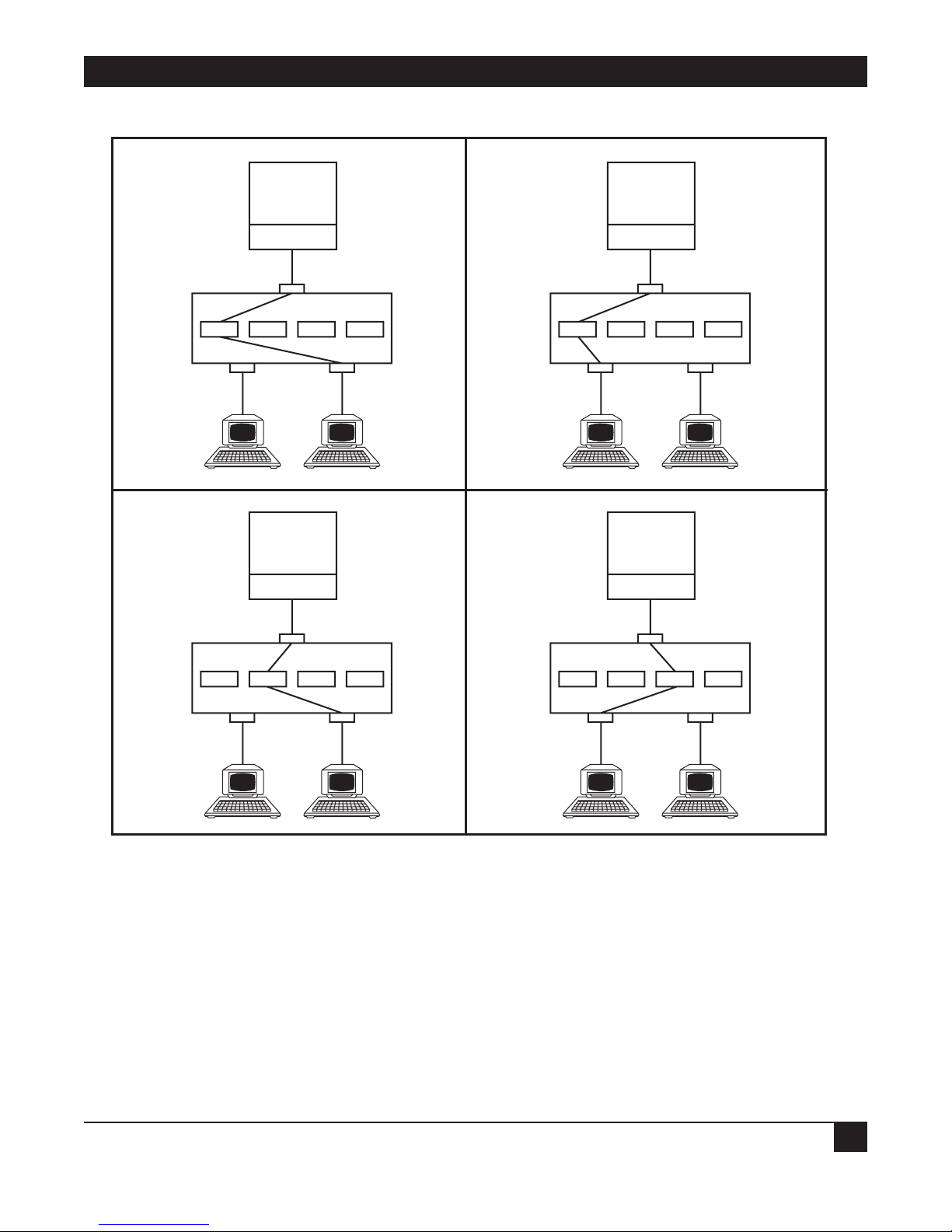
coupled at the same physical port. In Figure 3-2, several diagrams a provided to show these various LUport coupling options.
NOTE
Establishing a communication link with your System/3X host for each of these LUs
means you must define a workstation identification number (also called a local session
ID or LSID), recognized as viable by your host, to each LinkUp LU. This is done by
entering your host’s LSID to the LinkUp configuration parameter of Local Station
Address.
Page 20
CHAPTER 3: Features and Applications
19
Figure 3-2. Logical Unit to Physical Port Coupling Options.
LU2 to Port 2
LU4 to Port 5
LU9 to Port 5
1. LU 2 to Port 5
1. LU 2 to Port 5
System 3X
ICA
Sync PortLink Up 5294
LUX 2 LUX 4 LUX 9 LUX 32
Port 2 Port 5
ASCII
Terminals
System 3X
ICA
1. LU 2 to Port 5
1. LU 2 to Port 5
System 3X
ICA
Sync PortLink Up 5294
LUX 2 LUX 4 LUX 9 LUX 32
Port 2 Port 5
ASCII
Terminals
System 3X
ICA
Sync PortLink Up 5294
LUX 2 LUX 4 LUX 9 LUX 32
Port 2 Port 5
ASCII
Terminals
Sync PortLink Up 5294
LUX 2 LUX 4 LUX 9 LUX 32
Port 2 Port 5
ASCII
Terminals
Page 21
LINKUP 5294 WITH DL5294 FIRMWARE
20
The virtual device addressing concept also enables the LinkUp to support its Auxiliary Printer facility.
Once the appropriate configurations are made in the LinkUp, a terminal connected to an asynchronous
port can sign on to the LinkUp (at Connect Mode), specify an LU associated with an auxiliary printer
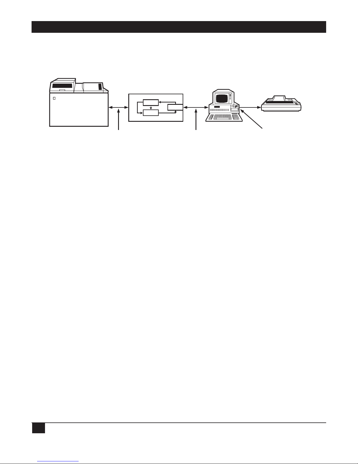
LU, and have both devices supported on that single port. See Figure 3-3 for a diagram of this feature.
Figure 3-3. Dual LU to Single Physical Port Coupling.
3.4 User-Friendly Facilities
The LinkUp is designed to be user-friendly. You should have very little, if any, difficulty operating it.
Here are some of the facilities that make the LinkUp 5294 easier to operate:
• A Menu-Driven Configurator Mode, enabling you to define a variety of operational parameters
by menu selections. These define the operating characteristics of the LinkUp’s synchronous
and asynchronous ports, logical units, and attached devices.
• Help Messages are available at each of the LinkUp operating mode menu prompts (including
Connect, Configurator, and Setup) whenever you type a <?> in response to the prompt.
• Non-volatile Electrically Erasable PROM (EEPROM) storage of every parameter value you define in
Configurator Mode. This enables the LinkUp to retain your configured values even when its power
is turned off.
• Password protection for Configurator Mode, preventing anyone from accessing it and redefining the
LinkUp parameter values unless authorized with the correct password.
• Operating and Channel Status Indicators on the front panel of the LinkUp unit. These let you
monitor your unit’s overall system health and the crucial RS-232C line signals for any port.
• Self-testing performed continuously in the background throughout daily operations. This assures you
that the LinkUp is effectively executing its operating programs.
• Automatic baud detection lets the LinkUp automatically detect the incoming baud (or bit) rate of
the device you have attached to its asynchronous port.
• An Inactivity Time Limit can be set in Configurator Mode. This enables you to define a maximum
amount of time for the LinkUp to maintain the coupling between your terminal, while it is inactive,
and its associated LU session.
• A Reconnect Time Limit can also be set in Configurator Mode. This time limit enables the LinkUp to
maintain the coupling between a disconnected terminal and its associated LU session. It lets you
reconnect and pick up from where the session was interrupted.
• Two-level password protection can be defined for each LinkUp LU whenever you define a Connect
Mode password in Configurator Mode. The first level allows the LinkUp to restrict access to an LU
from everyone except the one authorized with the correct password. The second one limits access to
an interrupted LU session from everyone except the one who initially established the session.
LinkUp 5294
DATALYNX/5294
(DSPLY)
IBM SYS/36
EIA RS-232C
INTERFACE
LU6
LU 15
(AUX)
PORT n
EIA RS-232C
INTERFACE
ASCII TERMINAL
PC, etc
ASCII PRINTER
AUXILIARY
PORT
Page 22

CHAPTER 3: Features and Applications
21
3.5 File-Transfer Support
The LinkUp can support file transfers between a System/3X host computer and an ASCII micro, mini,
or instrumentation computer, providing the appropriate host and ASCII computer communication and
transfer programs are installed. If the ASCII computer is an IBM Personal Computer (or compatible),
four software package combinations currently available in the market can be used with the LinkUp:
• FileLynx
®
/5251 PC* and Emulator Transfer Utility by SSI
• TruLynx
®
/5251 PC and Emulator Transfer Utility by SSI
• TruLynx/5251 PC and Emulator Transfer Utility by IBM
• TruLynx/5251 PC and PC Support by IBM
*FileLynx/5251 PC can also transfer files without the assistance of a host package by a simple screen-byscreen process. Consult your supplier for more information on the various capabilities of this software
package.
NOTE
PC Support/400 is not supported on the LinkUp 5294.
However, if the ASCII computer is not IBM compatible, you must provide your own communication and
transfer programs for both your 3X host and the ASCII computer. In support of such an application, the
LinkUp 5294 provides the COMPU Terminal Module. COMPU was designed especially for a computerto-computer transfer, and as such differs from the other Terminal Modules in the following ways:
1. Data alone is transmitted; for example, no intensity or cursor-positioning sequences are ever sent,
even if your 3X host requests them. This process enables the LinkUp 5294 to convert and pass on
the transferred data in the same order it was received.
2. Screen optimization is not performed; instead, the LinkUp completely updates a screen full of data
each time an update is required. (Usually, the LinkUp updates a screen of data by repainting only
the new data and clearing any old data not similar to the new data.)
3. Transferred data is completely buffered by the LinkUp 5294, enabling a continuous transmission of
data. Typically the 3X host inhibits transmission when it is processing received data by inhibiting
your keyboard input; normally, the LinkUp 5294 adheres to this procedure and ignores any
keyboard input you attempt.
NOTE
The COMPU module relies on the normal ASCII-to-EBCDIC and EBCDIC-to-ASCII
translations of the data handled by the LinkUp. Additionally, the key sequences defined
for its emulation keyboard functions are identical to those used for the ADM3A Terminal
Module.
Page 23

LINKUP 5294 WITH DL5294 FIRMWARE
22
3.6 Modify for 3174 Protocol
The DL5294 Firmware (PCM91) differs from the STD 3174 Firmware (PCM92) in the following aspects
only:
• PROM cartridge (the installed firmware)
• Internal EEPROM format
• Amount of RAM installed
• Silkscreened name on front panel of unit
Your LinkUp 5294 with DL5294 Firmware can be modified to support the 3174 protocol by doing the
following:
• Ordering the appropriate conversion kit from your supplier.
• Replacing and/or installing the respective parts (in accordance with the kit’s provided instructions).
• Invoking Setup Mode (explained in Section 7.7).
3.7 Port Test and System Management Modes
These two modes perform a variety of valuable diagnostic and information functions. Port Test Mode
consists of the following:
• Interface Signal Display (your port only)
• Character Display Test
• Character Echo Test
System Management Mode consists of the following:
• Interface Signal Display (any LinkUp 5294 port)
• Sync Port Address Trace
• Async Port Trace
• Product Configuration and Levels display
• Sync Port Trace
• Character Display Test (the same as in Port Test Mode)
• Character Echo Test (the same as in Port Test Mode)
• LU and Async Port Summary
• Remote Reset
• SNA/SDLC Counters
Port Test Mode is covered in Section 7.3. System Management Mode is covered in Section 7.4.
Page 24

CHAPTER 3: Features and Applications
23
3.8 5251/5294/5394 Emulation
With 5251, 5294, and 5394 controller emulation, the LinkUp 5294 can be configured to emulate two
different controllers concurrently on the LinkUp 5294’s two synchronous ports. In other words, both
ports can be configured to emulate either a 5251 Model 12 or a 5294 or 5394 controller, or one port
can be configured to emulate a 5251 Model 12 while the other emulates either a 5294 or 5394.
NOTE
Some capabilities of an actual 5294 or 5394 controller are not fully supported by the
LinkUp 5294. For example, Text Assist is not implemented; therefore, DisplayWrite is
not supported. Consult your supplier for more information on those capabilities not
supported.
3.9 Additional Features
• The LinkUp 5294 can be programmed for up to four controller emulations on one synchronous port
(or a maximum of four across the two synchronous ports).
• Five additional functions in System Management Mode (see Section 3.7 above for a description).
• 5394 Controller emulation.
When the capability of Four Controller Emulations Per One Synchronous Port is implemented, the
LinkUp 5294 appears to your host as if it were up to four distinct controllers (each with its own
System/3X controller address) on a multipoint line. The LinkUp 5294 supports this facility by mapping
each of the 3X controller addresses to the appropriate controller emulations by a logically defined Link
Station Address (identified as Links 0, 1, 2, and 3). If so configured, the LinkUp 5294 can emulate as
many as four distinct controllers across its two synchronous ports, in any combination (four addresses on
one port and none on the other, or three on one port and one on the other, etc.). See Section 7.5.
Operating a single LinkUp 5294 as multiple controllers requires that you divide the virtual device
addresses (logical units) among the controllers (identified as link station addresses). If your application
uses this capability, keep the following limitations in mind:
1. An IBM System/3X will activate at most nine logical units when connected to a 5251 Model 12
controller, only eight logical units when connected to a 5294 controller, or as many as 16 logical
units when connected to a 5394 controller.
2. The LinkUp 5294 can emulate up to four controllers simultaneously; those four may be a mix of
5251-12, 5294, and 5394 emulations.
3. Because it has a maximum of 32 logical units available, the LinkUp 5294 can have attached and
active at most 32 of the 36 logical units (nine LUs per controller times four 5251-12 controllers)
available to your host(s) if emulating 5251-12 controllers. Similarly, only 32 of the possible 64 logical
units (sixteen LUs per controller times four 5394 controllers) may be active during 5394 emulation.
When emulating 5294 controllers, the LinkUp can have all 32 of the host’s logical units attached and
active.
Page 25
LINKUP 5294 WITH DL5294 FIRMWARE
24
4. Hardware Overview
This chapter discusses the LinkUp 5294’s hardware components and capabilities.
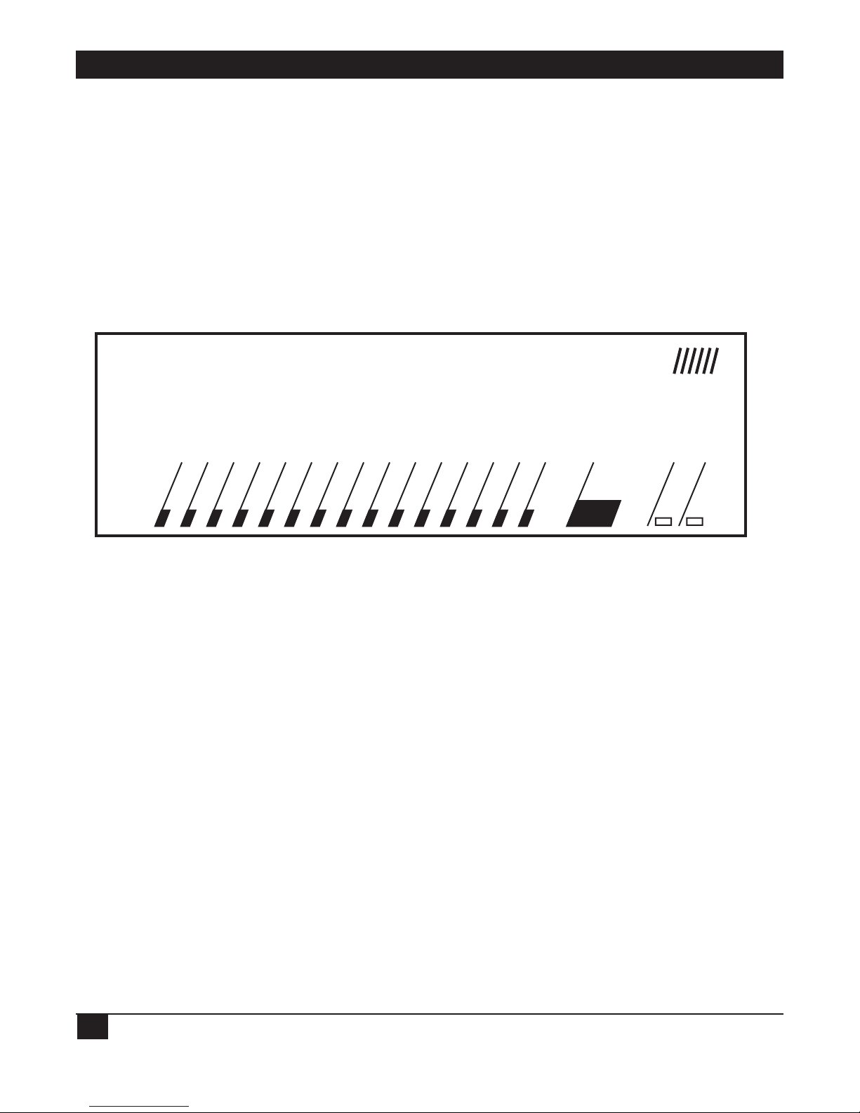
4.1 Front Panel
The front panel of the LinkUp 5294 is shown in Figure 4-1. Status indicators monitor power and RS232C line signals on the selected channel. Two user controls are provided for easy operation.
Figure 4-1. LinkUp 5294 Front Panel.
4.2 Front Panel Controls
Two front panel controls are provided on the LinkUp 5294: the CH SEL button and the RESET button.
Each of these controls is discussed below.
• CH SEL (Channel Select) Button — The CH SEL button is used to select the channel to be
monitored. When the button is pressed, the channel number increases. When held for a longer time,
the channel number is incremented at a faster rate. The channel being currently monitored is
indicated by the two-digit LED display.
If the channel number is incremented past the highest channel available in the unit, 88 appears in
the display and an LED integrity test is performed. All of the front panel lights are turned on to
ensure proper operation. Pressing the CH SEL button again terminates the LED test.
• The RESET Button — The RESET button is used to clear error codes from the front panel display.
Error codes are listed in of Section 9.1. When the first error occurs, pressing RESET clears the error
and channel status display resumes. If there is more than one error, the RESET button clears the
most recent error and displays the previous one. When all of the accumulated errors have been
displayed and cleared, the status lights resume their normal function. Once cleared, errors cannot be
redisplayed using the front panel. Therefore, you should write down any error codes that are
displayed before you press RESET.
DataLynx /5294
ON SYS OK DCE DTE TXD RXD RTS CTS DTR DSR CD RI/SYN TXC RXC I/O FLT CHANNEL ERROR CH SEL RESET
TM
Page 26

CHAPTER 4: Hardvare Overview
25
4.3 Channel Status Indicators
The LinkUp 5294 is equipped with a full RS-232C status display capable of monitoring the status of any
selected port. Each of the indicators is briefly described below. ON indicates that the LinkUp 5294 is
either transmitting or receiving the signal as appropriate.
• DCE/DTE (Data Communications Equipment/Data Terminal Equipment) — An LED lit for one of
these indicates that the port selected has been software-optioned to communicate with either a
modem (DTE) or directly to a terminal or printer (DCE).
• TXD/RXD (Transmit Data/Receive Data) — These are data signals that indicate transmission of data
either to or from the LinkUp 5294.
• RTS (Request to Send) — The LinkUp 5294 provides this signal when optioned as DTE or when it
expects to receive the signal when optioned as DCE.
• CTS (Clear To Send) — The LinkUp 5294 provides this signal when optioned as DCE and expects it
from the modem when optioned as DTE.
• DTR (Data Terminal Ready) — The LinkUp 5294 provides this signal when optioned as DTE or
expects to receive the signal when optioned as DCE. Additionally, when configured as DTE autoanswer, this signal will be provided only after receipt of the Rl (Ring Indicator) signal from the
modem.
• DSR (Data Set Ready) — The LinkUp 5294 provides this signal when optioned as DCE or expects to
receive it from the modem when optioned as DTE.
• CD (Carrier Detect) — This LED is lit when the LinkUp 5294 has detected a carrier signal from a
remote modem. If no detectable carrier signal is present, or the remote modem hangs up, this LED
is turned off.
• RI/SYN (Ring Indicator/Data Sync) — This is a dual-function LED. It displays Ring Indicate when
the selected port is optioned as DTE/auto-answer in synchronous or asynchronous operation. On
the sync port, this LED is always off.
• TXC/RXC (Transmit Clock/Receive Clock) — When on, this LED indicates the presence of
synchronous clock signals which are required for the sync port. These must always be present for
Port 0 and Port 1.
• I/O FAULT — On SYNC ports, this LED flashes if a framing error occurs. On asynchronous ports
this LED indicates parity errors.
During normal operation in async DTE mode, the following should be on:
DTE, RTS, CTS, DSR and CD
RI will be on during ringing, and DTR will come on after RI is detected.
During normal operation in async DCE mode, the following should be on:
DCE, RTS, CTS, DTR, DSR and CD
In both DTE and DCE modes, the TXD and RXD lights will blink during data transfer.
Page 27
LINKUP 5294 WITH DL5294 FIRMWARE
26
4.4 System Status Indicators
The following system status indicators are provided on the front panel.
• SYS OK — This LED blinks to indicate that the system is functioning properly. The LED acts as a
“heartbeat” indicator and is never turned off unless there is an unrecoverable error.
• ON — When on, this LED indicates that the power supply is functioning properly.
4.5 Error Code Display
When a program-detectable error occurs , all channel status indicators are turned off and a two-level
error code is displayed using the two-digit channel display. The two error codes are flashed alternately.
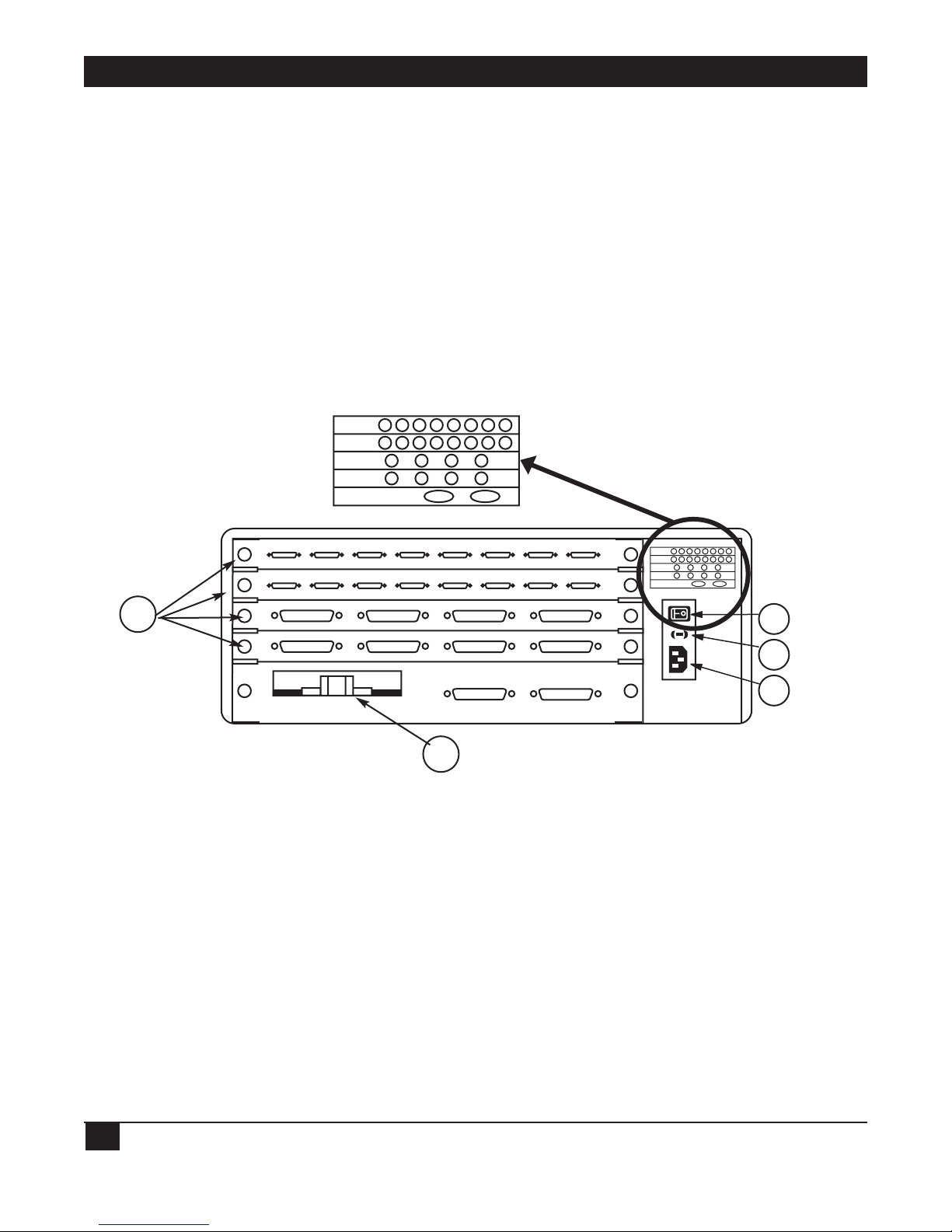
4.6 Rear Panel
The rear panel of the LinkUp 5294 is equipped with the following:
1.Up to 34 serial (RS-232/V.24 compatible) Ports, numbered 0 through 33.
2.An A.19/.15, 50/60 Hz air flow fan.
3.A rocker-type on/off power switch.
4.A 1-amp, 250-volt fuse just below the power switch (which can be removed by sliding out the rubber
fuse cartridge with a screwdriver).
5.A power cord receptacle (below the fuse).
1
2
PORTS:
18 19 20 21 22 23 24 25
PORTS:
10 11 12 13 14 15 16 17
PORTS:
PORTS:
340-0036-02
6 7 8 9
2 3 4 5
0 1
PORTS:
18 19 20 21 22 23 24 25
PORTS:
10 11 12 13 14 15 16 17
PORTS:
6 7 8 9
2 3 4 5
PORTS:
0 1
340-0036-02
3
4
5
Page 28

CHAPTER 5: Electrical Characteristics
27
5. Electrical Characteristics
This chapter covers the power specifications of the LinkUp 5294 and the requirements of the
RS-232C interface for synchronous and asynchronous communications.
5.1 Power Specifications
The LinkUp 5294 power supply is rated at 50 watts and operates on 115 or 230 volts (plus or minus 15%)
at 50 or 60 Hz (plus or minus 2 Hz). Its power connector is the international standard CEE-22.
NOTE
Units with 115 volts are shipped with a 7-foot NEMA 5-15P three-prong plug.
The LinkUp 5294 is certified to operate in accordance with the following standards:
• UL — Underwriters Laboratory: Listed with EDP Equipment/Office (Standards 478), File No.
E87479.
• CSA — Canadian Standards Association: Certified.
• IEC — International Electrotechnical Commission: Designed to meet IEC 380.
• BPO — British Post Office: Meets the requirements of Technical Guide #26.
• FCC — Federal Communications Commission: Complies with the requirements of U.S. 47CFR Part
15 Subpart J, Class B, assuming shielded RS-232C cables are used.
5.2 Cable Pin Requirements
All of the ports on the LinkUp 5294 support the standard EIA RS-232C interface signals. In the next
three sections, the signals specific to synchronous and asynchronous communications are identified.
Synchronous Port
A minimum conductor synchronous cable that will work with Bell compatible sync modems and the
LinkUp 5294 in Modem Eliminator mode requires the following pins: 1 through 8, 15, 17, and 20. If the
LinkUp 5294 is to be dialed from the host, Pin 22 most also be supported.
1 Frame Ground 1
2 Transmit Data (TxD) 2
3 Receive Data (RxD) 3
4 Request To Send (RTS) 4
5 Clear To Send (CTS) 5
6 Data Set Ready (DSR) 6
7 Signal Ground 7
8 Data Carrier Detected (DCD) 8
15 Transmit Clock (TxC) 15
17 Receive Clock (RxC) 17
20 Data Terminal Ready (DTR) 20
22 Ring Indicator (RI) 22
Page 29

LINKUP 5294 WITH DL5294 FIRMWARE
28
Asynchronous Port with DB25 Connector
The minimum requirements of an asynchronous RS-232C cable for use with dedicated terminals provide
Pins 1 through 8 and 20. The minimum requirements for use with auto-answer modems provide Pins 1
through 8, 20, and 22.
For directly-connected printers, certain printer types may use Pin 11 to supply a Not Busy signal.
1 Frame Ground 1
2 Transmit Data (TxD) 2
3 Receive Data (RxD) 3
4 Request To Send (RTS) 4
5 Clear To Send (CTS) 5
6 Data Set Ready (DSR) 6
7 Signal Ground 7
8 Data Carrier Detected (DCD) 8
11 Busy 11
20 Data Terminal Ready (DTR) 20
22 Ring Indicator (RI) 22
Asynchronous Port with DB9 Connector
Cable pinouts for the RS-232C DB9 connector are shown below.
1 Data Carrier Detected (DCD) 1
2 Receive Data (RxD) 2
3 Transmit Data (TxD) 3
4 Data Terminal Ready (DTR) 4
5 Signal Ground 5
6 Data Set Ready (DSR) 6
7 Request To Send (RTS) 7
8 Clear To Send (CTS) 8
9 Ring Indicator (RI) 9
Page 30

CHAPTER 6: Installation
29
6. Installation
This chapter describes installation of the LinkUp 5294. A typical local installation to a single host is
described. Attachment of local and remote (to the LinkUp 5294) terminals and printers is also included
in Sections 6.3, 6.4, and 6.5. Special considerations for dual host and remote host environments are
described in Section 6.6.
Information regarding the configuration of the communication and work station parameters for
the System/36 and the System/38 is given in Appendices E and F, respectively, of this manual.
6.1Installing the LinkUp 5294 and the Configuration Terminal
Configuration and installation of the LinkUp 5294 requires attachment of an asynchronous terminal
to one of the asynchronous ports. The terminal is then used in conjunction with the Configurator menus
to set the logical configuration parameters. The terminal used for this purpose is referred to as the
Configuration Terminal throughout this section.
We recommend that a local terminal be used for initial installation and configuration. This will simplify
problem isolation during the installation process. Therefore, the following sections assume that the
configuration terminal will be locally attached to the LinkUp 5294. If a remote terminal must be used,
see Section 6.4.
6.1.1 U
NPACK THE LINKUP 5294
The LinkUp 5294 is carefully packed in a 25.5" x 15.8" x 11" box. A label on the outside of the box lists
the model of the unit, serial number, firmware version number, date of manufacture, voltage setting of
the power switch (115 or 230 VAC), and other electrical information. Inside you will find a a release
notice for the latest firmware version, a power cord, and the LinkUp 5294.
Carefully remove the contents of the box and check to see that the above items are present. If an item is
missing or defective call your supplier.
NOTE
The power cord shipped with units set for 230-volt operation does not include an AC
plug. You must supply the appropriate plug.
6.1.2 I
NSTALL THE LINKUP 5294
The only additional equipment needed to install the LinkUp 5294 is an asynchronous terminal, or
personal computer with terminal emulation software installed, and an appropriate length of RS-232C
cable. You may also want a small for tightening the cable connection.
The LinkUp 5294 is shipped with all asynchronous RS-232C ports configured as follows:
• DCE
• Autobaud
• 8 bits/character
• No parity
• 1 stop bit
Page 31

LINKUP 5294 WITH DL5294 FIRMWARE
30
The location of the LinkUp 5294 is not critical as long as the maximum recommended cable lengths are
not exceeded. Temperature and humidity are considerations; however, the LinkUp 5294 is no more
sensitive than other computer or data-processing equipment. During initial installation and testing, it
may be helpful to position the LinkUp 5294 so that the front-panel indicators are easily visible.
6.1.3 S
ET UP THE CONFIGURATION TERMINAL
Refer to Appendix G for information on setting up your terminal for use with the LinkUp 5294. Ensure
that the configuration terminal is set for initial operation with the following values:
• No parity
• 8 data bits
• 1 stop bit
Seven data bits and even parity is also allowed during initial configuration. This configuration allows use
of virtually any asynchronous display terminal for configuration. These values are the initial default
values for parameters that may be changed later to suit specific requirements.
6.1.4 C
ONNECT THE CONFIGURATION TERMINAL
Connect the terminal to an asynchronous port of the LinkUp 5294 using a standard RS-232C cable. See
Section 5.2 for required cable pinouts. No other data cable connections are required now.
6.1.5 ESTABLISH COMMUNICATION
Power on both the LinkUp 5294 and the terminal. Allow a short time, approximately 2 or 3 seconds, for
the LinkUp 5294 to perform its internal power-on self tests. Once the selftests are completed and all
systems are functioning normally, the SYS OK LED on the front panel begins blinking slowly and 02
appears in the CHANNEL/ERROR display. If this does not occur, see Chapter 9.
A banner message similar to the following is displayed on the screen:
***5294 CONTROLLER EMULATOR - V1.00U3***
(For Help, Type '?' after any Prompt. To Abort Connect Sequence, Type 'I')
(To Delete Response Characters, use 'Rubout'. To Cancel Response, 'ctrl x'.)
The connection is complete when the following prompt appears on the terminal screen:
Enter Device Type (ADM3A):
6.1.6 S
ELECT A DEVICE TYPE
Determine the appropriate Terminal ID for your terminal and enter it in response to the Enter Device
Type prompt.
Type a question mark <?> or refer to Appendix G for a list of valid terminal types. If you are using a
terminal that is not listed directly, but which emulates one of the supported terminals, use the Terminal
ID for the emulated terminal.
NOTE
A question mark <?> followed by <Enter> is a valid response at any time during
Connect and Configuration Modes. It displays a brief description of the response
expected by the LinkUp 5294.
Page 32

CHAPTER 6: Installation
31
6.2 Accessing the LinkUp 5294 Configurator
This section describes access to the Configurator Mode of the LinkUp 5294. Since logical configuration
is unique for each installation, all system information pertinent to this control unit and its attached
devices must be readily available and understood before proceeding.
To enter System Management Mode, follow these steps:
1. Establish the connection and enter the appropriate Device Type as described in Section 6.1. The
prompt “Enter LU Number (0):” is displayed.
2. Enter Port Test Mode by typing 1 in response to the above prompt. The Port Test Mode Menu
appears.
3. Select Option 1 from the Port Test Mode Menu to enter System Management Mode. The first entry
into System Management Mode requires no password, but the prompt, “Specify New System
Password:”, appears. Enter a new password to protect against unauthorized access to System
Management Mode.
NOTE
If the LinkUp 5294 has been previously configured, you may be prompted to enter a
password before entry into System Management Mode is allowed. Get the correct
password from the System Manager. (If the password is not known, see Section 7.7 of
this manual.)
After entry of a password (if required) and/or a new password (or Enter), the System Management
Mode menu is displayed.
4. Select Option 1, Configurator Mode, fran the System Management Mode menu. The prompt “Enter
Item to be Configured:” appears, indicating that you are in Configurator Mode. Refer to Chapter 7
for compete details on use of the Configurator.
Configure the synchronous port, asynchronous port, and LU parameters as required for your
installation. Save the changes by entering END at the Enter Change(s): prompt. Exit Configurator
and System Management Modes using the same command.
6.3 Connecting Additional Local Terminals
Having specified port characteristics to the LinkUp 5294 with the Configurator, ensure that additional
terminals you connect are configured correctly. For further information refer to Appendix G, which
gives individual setup details for all supported terminal types, or consult the literature provided by the
terminal manufacturer.
Connect each terminal to the appropriate asynchronous port of the LinkUp 5294 using a standard RS232C cable.
NOTE
When attaching devices to those ports having DB9 connectors, DB9-to-DB25 converter
cables may be required. Standard IBM AT serial cables, available from your local PC
dealer, may be used.
Page 33

LINKUP 5294 WITH DL5294 FIRMWARE
32
6.4 Connecting Remote Terminals
For remote terminals, full-duplex asynchronous modems are required. The modems attached to the
LinkUp 5294 ports should be configured properly for switched or dedicated lines.
6.4.1 LINE CONFIGURATION
Modems on the LinkUp 5294 end of switched lines should permit the following:
• Auto-answer mode.
• Loss-of-Carrier disconnect (causes modem to drop DSR and return to auto-answer state if phone line
becomes disconnected).
• External DTR control (causes modem to disconnect from phone line if the LinkUp 5294 drops
DTR).
6.4.2 M
ODEM CONSIDERATIONS
Auto-answer modems must be optioned to pass Ring Indicator (Pin 22) to the LinkUp 5294 and for DTE
control of DTR (Pin 20). In auto-answer mode, the LinkUp 5294 raises DTR in response to a positive
going signal on Ring Indicator. The Ring Indicator signal must be set to be held low or negative except
when ringing occurs. See the literature provided with the modem.
User-friendly messages which are generated by some modems (such as Connect) must be disabled. Such
messages will interfere with the LinkUp 5294 autobaud detection, causing error during connection.
Connect the modem to the switched or dedicated communication line as appropriate. Connect the
modem to an asynchronous port on the LinkUp 5294 using an RS-232C cable. (The LinkUp 5294 port
must be configured for DTE operation.)
Connect the terminal to the other modem with an RS-232C cable. Then connect the modem to an
appropriate communications line.
6.5 Connecting Printers
Printers may be connected to the LinkUp 5294 in one of two ways. Printers which use a serial interface
(RS-232C cable) may be connected directly to the LinkUp 5294 using one of the asynchronous ports.
The attachment may be either local, using only a cable, or remote, using a pair of modems. An
alternative is to attach the printer through the auxiliary port of a terminal which is in turn attached to
the LinkUp 5294. Special considerations for installation of printers are discussed in the following
paragraphs.
6.5.1 L
OCAL PRINTERS
The following information applies if a directly attached printer is used:
• The port to be used must be configured with no overridable parameters, since the printer cannot be
used to answer Connect Mode prompts.
• Configure the LU associated with the port as a PRT (printer) LU.
• Connect the printer to one of the async ports on the rear of the LinkUp 5294. Make sure that the
port interface parameters agree. The autobaud option cannot be used for printers.
Once the printer is turned on and put on line, it should be recognized by the LinkUp 5294. If the host
is properly configured, there is no further action required.
Page 34

CHAPTER 6: Installation
33
6.5.2 REMOTE PRINTERS
In addition to the considerations listed above, the following applies to remote printers:
• Connect the printer to the modem as instructed by the modem manufacturer’s literature. A
telephone is required to dial the number unless the printer or modem provides an alternate dialing
method.
• The LinkUp 5294 modem should be optioned for Auto Answer if the printer operator will be dialing
into the port. Set the communications parameters of the printer, modems, and the LinkUp 5294 port
to match. A fixed baud rate must be used.
At the LinkUp 5294 site, the operator can monitor the port and observe the Ring Indicator flashing
during the dial-up. Once the LinkUp 5294 answers the call, the DTR and DSR lights will remain on. If
this does not happen, refer to Chapter 9 for help in correcting the problem.
6.5.3 A
UXILIARY PRINTERS
The following considerations apply to auxiliary printers attached directly to remotely connected
terminals.
• Verify that the auxiliary port of the chosen terminal is supported by the LinkUp 5294. Refer to the
Appendix G for a list of terminals which support auxiliary printers.
• Connect the printer to the auxiliary or printer port of the terminal. Set the auxiliary port parameters
to agree with the printer requirements.
• The LU associated with the terminal must be configured to support an auxiliary printer LU. The
printer itself is defined through configuration of its own LU.
Page 35

LINKUP 5294 WITH DL5294 FIRMWARE
34
6.6 Connecting the LinkUp 5294 to the Host Computer
The LinkUp 5294 can be attached to the host front end in one of three ways as shown in
Figure 6-1.
As shown in Figure 6-1, the DTE/DCE setting of the port depends on the type of connection used.
Method 1:
If the LinkUp 5294 is attached using a pair of synchronous modems, the sync port must be configured
as DTE. The two modems are connected through a dial-up or dedicated line. In such an installation,
clocking is typically provided by the modem; thus the LinkUp 5294 bit rate must be set for EXTERNAL
clocking. Refer to the modem manufacturer’s literature for instructions on setting the modem for
Internal Clocking and Carrier Controlled by Request to Send.
Method 2:
This method is used when the LinkUp 5294 is installed in close proximity to the S/3X. The connection
consists of a single cable with no other communications equipment. In this case, the LinkUp 5294 sync
port must be configured as DCE. The bit rate is controlled by the LinkUp 5294 and is set during
configuration of the sync port. The LinkUp 5294 uses an internal modem eliminator which provides the
necessary clocking signals.
LINKUP 5294
DTE
LINKUP 5294
LINKUP 5294
DTE
SYSTEM/3X
MODEM
MODEM MODEM
ELIMINATOR
TM
DataLynx /5294
ON SYS OK DCE DTE TXD RXD RTS CTS DTR DSR CD RI/SYN TXC RXC I/O FLT CHANNEL ERROR CH SEL RESET
DATALYNX/5294
DCE
(METHOD 1)
ON SYS OK DCE DTE TXD RXD RTS CTS DTR DSR CD RI/SYN TXC RXC I/O FLT CHANNEL ERROR CH SEL RESET
DATALYNX/5294
DCE
(METHOD 2)
DataLynx /5294
TM
ON SYS OK DCE DTE TXD RXD RTS CTS DTR DSR CD RI/SYN TXC RXC I/O FLT CHANNEL ERROR CH SEL RESET
DATALYNX/5294
DCE
(METHOD 3)
DataLynx /5294
TM
Page 36

CHAPTER 6: Installation
35
Method 3:
This method is similar to Method 1 except that a modem eliminator is used in place of the pair of
modems and the intervening line. The LinkUp 5294 port is set as DTE and the bit rate is controlled
externally.
A special case of such an installation is an X.25 network environment. The Modem Eliminator depicted
in Figure 6-1 could be a very complex network which connects a variety of devices in addition to the
LinkUp 5294 and the host.
6.6.1 REQUIREMENTS
Before connecting to the host, get the following information so that you can configure the synchronous
ports correctly.
• Link Station address. (If both ports 0 and 1 are used, they may have the same Link Station number.)
• Bit Rate. Use external clocking if the LinkUp 5294 is set for DTE, or specify a bit rate if the LinkUp
5294 is DCE.
• Whether NRZI (Non-Return to Zero Inverted) encoding is used.
• Line configuration half or full duple). If a half- duplex line is used, the LinkUp 5294 will wait for
CTS from the modem before sending data.
6.6.2 D
UAL HOST INSTALLATIONS
By using the LinkUp 5294’s two synchronous ports, you can enable the LinkUp 5294 to emulate up to
four controllers. These controllers can be defined to communicate with different host computers. For
example, a System/34 host can be attached to one of the synchronous ports, while a System/38 host can
be connected to the other port. Under this application, you can select which host you want to access by
specifying the appropriately associated logical unit during Connect Mode.
Figure 6-2 shows a dual host application with the LinkUp 5294 remotely connected to two different host
computers. In this example, the 32 logical units have been divided between the two synchronous ports as
follows:
• LU 0 and 2 through 16 - Port 0
• LU 17 through 32 - Port 1
Page 37

LINKUP 5294 WITH DL5294 FIRMWARE
36
6.6.3 ESTABLISH COMMUNICATION WITH THE HOST
If the LinkUp 5294 is configured as DTE:
The DTE and DTR indicators should come on when all of the equipment is connected and powered on.
After the modem is powered on, the TXC and RXC lights will indicate the clocking signals. After the
host connection is completed, CTS, RTS, CD, TXD, and RXD should also be present.
If the LinkUp 5294 is configured as DCE:
When all of the equipment is connected and powered on, the DCE, CTS (if full-duplex), DSR, TXC,
and RXC lights should come on. After the host connection is completed, RTS, CD, TXD, and RXD
should also be present.
If the correct front panel signals are not present, refer to Chapter 9. If neither the TXD nor RXD light
is flashing, there is no synchronous line between the LinkUp 5294 and the host computer. Contact the
host operator and make sure that the line has been activated.
LINKUP 5294
System/34 System/38
RS-232C Interface
DataLynx/5294
Port 0 Port 1
LU 0 LU 9 LU 16 LU30 LU 31 LU 32
Synchronous
Port 8Port 5Port 2
ASCII Terminals, PCs, Printers
Page 38

CHAPTER 7: Operation
37
7. Operation
The LinkUp 5294 operates in six different modes:
1. Connect Mode — typically the operating session encountered prior to accessing the others; allows
you to sign on to the LinkUp 5294.
2. Port Test Mode — allows you to perform several diagnostic and information functions: Interface
Signal Display, Character Display Test, and Character Echo Test.
3. System Management Mode — allows you to perform the following diagnostic and information
functions:
• Interface Signal Display (similar to the function in Port Test Mode)
• Sync Port Address Trace
• Async Port Trace
• Product Configuration and Levels Display
• Sync Port Trace
• Character Display Test (also provided in Port Test Mode)
• Character Echo Test (also provided in Port Test Mode)
• LU and Async Port Summary
• Remote Reset
• SNA/SDLC Counters
4. Configurator Mode — enables you to define the operating and environmental characteristics in
which the LinkUp 5294 will function.
5. Emulation Mode — the standard operating session encountered by a terminal operator
communicating with the System/3X host.
6. Setup Mode — lets you restore the factory default configuration parameter values defined in the
LinkUp 5294.
7.1 Operating Requirements
To establish an operating session with the LinkUp 5294 the following hardware and software
requirements must be met:
7.1.1 CABLES AND CONNECTIONS
As discussed in Chapter 5, all LinkUp 5294 connectors (ports) support a standard RS-232C interface.
Each device or 3X host Integrated Communications Adapter (ICA) must be connected to the LinkUp
5294 by a shielded RS-232C cable.
When a terminal, printer, personal computer, or 3X host is attached directly to a LinkUp 5294 port, it is
called a Local connection; when they are attached by modems, it is called a Remote connection.
(Remote connections can be through switched or dedicated lines.)
Page 39

LINKUP 5294 WITH DL5294 FIRMWARE
38
7.1.2 SYSTEM/3X HOST
On the synchronous side, the LinkUp 5294 must be attached either directly (by its integrated modem
eliminator) or remotely (by synchronous modems) to your System/3X host’s ICA. As previously
discussed, the adapter can be any of the following:
• A single-line communications adapter
• A multi-line (equal to four lines) communications adapter
• An eight-line communications adapter
CAUTION:
Your 3X host’s communication line must be configured comparably to the parameters
of the LinkUp 5294.
7.1.3 ASCII T
ERMINAL
Virtually any ASCII terminal can be used to operate the LinkUp 5294; however, it must be compatible
with one of the Terminal Modules supported by the LinkUp 5294. See Appendix D for a list of those
terminals currently supported.
Your selected terminal must also be set up according to the following general terminal configuration or
switch settings:
• Character Mode = ON (as opposed to Block or Line Mode)
• Full Duplex = ON
• Auto New Line = OFF (if switch-selected)
• Auto Line Feed = OFF
• Cursor addressing = ON
• Auto Scroll = OFF (if switch-selected)
• DTR and DCD = ON, DSR = OFF (if switch-selected)
• Baud Rate = LinkUp 5294 configured settings
• Word Length (composed of Data Bits, Parity, and Stop Bits) = LinkUp 5294 configured settings (most
commonly implemented as 8 data bits, no parity, and 1 stop bit)
• Keyboard must be decoupled from the display (if switch selected). See note below.
NOTE
The LinkUp 5294 must handle any and all screen changes to the terminal. This means
the terminal must be set so that whenever a key is pressed on the keyboard, its
character is transmitted directly to the LinkUp 5294 rather than to the terminal’s display.
This setup is commonly called Conversational Mode. If your terminal’s keyboard cannot
be decoupled from its display (Conversational Mode = ON), you should avoid using
those keys which locally affect the display. If they are not avoided, the result will be a
garbled display, requiring you to invoke the LinkUp 5294 Refresh Screen extended
keyboard function.
Page 40

CHAPTER 7: Operation
39
7.1.4 PERSONAL COMPUTERS AND TERMINAL EMULATION SOFTWARE
In order for the LinkUp 5294 to operate with a personal computer or word processor, a terminalemulation software package must be installed on the PC or word processor and must be compatible with
one of the Terminal Module IDs provided by the LinkUp 5294. See Appendix D of this manual for a list
of those personal computers and word processors currently supported, as well as suggested terminalemulation software packages.
7.1.5 ASCII P
RINTER
When using an ASCII printer, be sure to confirm that its switch-selected parameters match those
configured in the LinkUp 5294. For example, the RS-232C line signals for physical flow control
(equivalent to the printer’s Not Busy signal) and device ready (the printer’s Off-line signal) or the
printer’s logical flow control code.
7.1.6 M
ODEMS
When you are remotely located from the LinkUp 5294, you must communicate with the LinkUp 5294
over switched or dedicated lines in full -duplex mode with asynchronous modems. When a switched line
is used, be sure to confirm that the modems are optioned as follows:
• The modem automatically answers an incoming call
• The DCD line state must not be held artificially high
• The modem should hang up when DTR drops
• The modem (attached to the LinkUp 5294) must not echo commands or characters.
When the LinkUp 5294 is remotely located from your System/3X host, it must communicate with your
host over switched or dedicated lines in half- or full-duplex mode with synchronous modems. To assure
that this remote connection is operating optimally, be sure to confirm that your modems are optioned as
follows:
• The modem provides clocking (internal)
• The modem allows the LinkUp 5294 to control CD by RTS
7.1.7 P
ACKET NETWORK TERMINAL NODE
The LinkUp 5294 can be configured to operate in an asynchronous data packet network in one of two
generic ways:
• The LinkUp 5294 recognizes that the terminal PAD echoes all hex values, which means the PAD
performs all cursor-positioning functions.
• The LinkUp 5294 recognizes that the terminal PAD echoes only certain hex values.
In the second situation, the PAD (or terminal node) might be set up to echo only displayable characters:
those including hexadecimal values 20 to 7E. When a PAD is set up in this way, the LinkUp 5294 is not
able to suppress your input to a non-display field, such as during a password entry. This means that your
input will display even though it should not.
Another PAD option might include setting it to echo some of the ASCII control codes within the range
of 00 through 1F hex as well. This setting combined with one or both of the following PAD options
would give the LinkUp 5294 limited control over the terminal’s cursor positioning.
Page 41

LINKUP 5294 WITH DL5294 FIRMWARE
40
• Setting the node to forward packets of data to the LinkUp 5294 after receipt of a control code hex
value of 00 through 1F and 7F from the he terminal.
• Setting the node to forward packets of data to the LinkUp 5294 after a specified time (in
milliseconds) of terminal inactivity has transpired.
For example, in this PAD-configured environment, the LinkUp 5294 could support the System/3X field
auto-exit capability. When a PAD echoes characters, the LinkUp 5294 is unable to move the cursor
according to this standard 3X facility unless it is notified in some way to do so. Setting the PAD with
either of these options will succeed in notifying the LinkUp 5294.
7.2 Connect Mode
As shipped from the factory, Connect Mode is the first operating session you will establish with the
LinkUp 5294. Once established, you can select which mode you want to access next.
NOTE
Depending on your operating criteria, you may restrict your terminal operators from
ever encountering this mode. If restriction is desired, then you must define the LinkUp
5294 configuration parameter values (found in Configurator Mode) as non-overridable.
7.2.1 S
IGN-ON MENU
The Connect Mode sign-on menu consists of a display of the firmware version number (represented as
V1.xxxx, where x is any integer from 0 to 9) installed in the LinkUp 5294, followed by the first of as many
as 15 menu prompts. A sample screen is shown below.
***5294 CONTROLLER EMULATOR -V1.00U3***
Enter Device Type (ADM3A):
As the LinkUp 5294 is shipped from the factory, this menu will appear immediately after you press your
selected ASCII terminal’s <Enter> key twice. This procedure lets the LinkUp 5294 automatically detect
the incoming baud rate of your terminal and match it.
Page 42

CHAPTER 7: Operation
41
7.2.2 MENU PROMPTS AND PARAMETERS
As previously mentioned, when the Connect Mode Sign-On screen displays, a sequence of menu
prompts follows. In general, the format of these prompts is: ENTER “parameter name” (default value):.
Each prompt allows you to confirm the default value for a specific LinkUp 5294 configuration
parameter, or enter a new value. The number of menu prompts which ultimately display depends on
which of the following parameters (if any) are defined as overridable during Configurator Mode:
• Device type
• Logical Unit Number
• Password protection (at two levels)
• Inactivity Time Limit
• Reconnect Time Limit
• Local Copy Printer LU Number
• Auxiliary Printer LU Number
• Setup parameters for Auxiliary Printer (page length, line density, etc.)
As the LinkUp is shipped from the factory, your initial Connect Mode Sign-On screen will display only
two menu prompts:
Enter Device Type (ADM3A):
Enter LU Number (0):
A sample Connect Mode session where all of the possible configuration parameters have been defined as
overridable is shown in Figure 7-1. Items underlined are those keyed in by a terminal operator.
Page 43

LINKUP 5294 WITH DL5294 FIRMWARE
42
Enter Device Type (ADM3A): <Enter>
Enter LU Number (3): 5 <Enter>
Enter Password: MYLU <Enter>
Specify Reconnect Password: RECON <Enter>
Enter Inactivity Time Limit (10): NONE <Enter>
Enter Reconnect Time Limit (30): 20 <Enter>
Echoplex Enable (YES): <Enter>
Echoplex Toggle Enable (NO): <Enter>
Enter LU Number of Local Copy Printer (17): <Enter>
Enter LU Copy of Auxiliary Printer (NONE): 9 <Enter>
Auxiliary Printer Device Type (PRINT): <Enter>
Enter Page Length (11.00): <Enter>
Enter Lines Per Inch (6): <Enter>
Enter Single/Dual Case (D): <Enter>
Enter Single/Double Spacing (S): <Enter>
Emulate Form Feed with Line Feeds (NO): AUTO
Page 44

CHAPTER 7: Operation
43
Refer to Section 7.5.7 for the definition and values appropriate to the following menu prompt
parameters:
• Device Type
• LU Number
NOTE
Entering 1 at the LU Number prompt during Connect Mode will advance you to Port Test
Mode if the internal RUN/SETUP switch is on RUN. It will advance you to Setup Mode if
the internal switch is on SETUP. (See Section 7.7).
Refer to Section 7.5.8 for the definitions and values corresponding to the following parameters:
1. Password
2. Reconnect Password
3. Inactivity Time Limit
4. Reconnect Time Limit
5. Echoplex Enable
6. Echoplex Toggle Enabled
7. LU Number of Local Copy Printer
8. LU Number of Auxiliary Printer
Refer to Section 7.5.9 for the definitions and values corresponding to the following parameters:
1. Auxiliary Printer Device Type
2. Page Length
3. Lines Per Inch
4. Single/Dual Case
5. Single/Double Spacing
6. Emulate Form Feed with Line Feeds
NOTE
Although the parameters 2 through 5 above are displayed and allow you to enter valid
values, they are not used or supported by the LinkUp 5294 at this time.
A secondary Connect Mode sign-on screen is shown below.
****5294 CONTROLLER EMULATOR - V1.00U3***
Enter Device Type (ADM3A):
Enter LU Number (3): 5
Enter Reconnect Password:
Page 45

LINKUP 5294 WITH DL5294 FIRMWARE
44
This screen displays only if a Reconnect Time Limit is defined and the connection established with the
LinkUp 5294 is either physically or logically disconnected. An example of a physical disconnection
would be if a remotely established communication line hung up. An example of a logical disconnection
would be if an Inactivity Time Limit was defined in the LinkUp 5294 by Configurator Mode and the
LinkUp 5294 timed out after the specified time limit was reached.
NOTE
The menu prompt requesting a Reconnect Password only displays if a password was
specified in the LinkUp 5294 through the Configurator Mode.
Refer to Section 7.5 of this manual for further information about the LinkUp 5294
facilities supporting this secondary sign-on screen.
7.2.3 E
DITING INSTRUCTIONS
The following key sequences are valid to edit the Connect Mode menu prompts:
• RETURN or ENTER (<Enter>) — Enters the typed response. If no response is typed at the prompt
prior to pressing <Enter>, the default value is assumed for the prompt and the next prompt in the
connect sequence is displayed.
• <BACKSPACE> or <DELETE> — Deletes the last character typed.
• <CTRL/X> — (Press these keys simultaneously.) Deletes all characters
typed at the current prompt.
NOTE
Remote connections require you to answer each prompt within five minutes. If this time
limit is exceeded, the LinkUp 5294 will abort your Connect Mode attempt and drop the
line.
The following three entries are valid responses for each of the Connect Mode menu prompts:
• <!> — Restarts Connect Mode beginning with the first prompt.
• parameter value — Any one of those defined as appropriate for each prompt. (If an invalid
parameter is entered, or a valid one incorrectly typed, then an error message will display.)
• <?> — Displays a help message which includes the range of valid values for the current parameter. If
you get lost or confused, <?> will usually give enough help to allow you to find your bearings. Certain
help messages cause the screen to be cleared before display. The screen will also be cleared when
full.
7.2.4 E
RROR MESSAGES
If invalid entries are made during Connect Mode, one of the following self-explanatory messages will
display on your screen.
Page 46

CHAPTER 7: Operation
45
Value Errors:
SYNTAX ERROR.
UNRECOGNIZED RESPONSE.
ILLEGAL CHARACTER.
MAXIMUM STRING LENGTH EXCEEDED.
MAXIMUM LINE LENGTH EXCEEDED.
VALUE OUT OF RANGE.
INVALID.
TRAILING CHARACTERS IGNORED.
NOT SUPPORTED IN THIS RELEASE.
Compatibility Errors:
LU# NOT AVAILABLE.
LU# NOT COMPATIBLE WITH DEVICE TYPE.
LU# NOT PRINTER TYPE.
LU# NOT AUX PRINTER TYPE.
DISPLAY DOES NOT SUPPORT AUXILIARY PRINTER
**CAUTION** (PAGE LENGTH X LINES PER INCH) HAS NON-INTEGER
RESULT; LINE COUNT PER PAGE NOT UPDATED.
Operational Error:
INACTIVITY TIME LIMIT EXCEEDED.
CONNECT REQUEST FAILED.
UNABLE TO READ EEPROM. DEFAULT CHARACTERISTICS ASSUMED.
7.3 Port Test Mode
Port Test Mode uses various port tests and traces which use the following conventions:
• Data from the LinkUp 5294 to the terminal or host is enclosed in square brackets ([ ]).
• Data from the terminal or host to the LinkUp 5294 is displayed without brackets.
• Complete messages, which could consist of only a single character, are separated by a space.
• Data is displayed on the first 23 lines of the screen, with line 24 reserved for messages. If the terminal
supports dual intensity, the first set of 23 data lines are displayed in low intensity. When 23 lines have
been displayed, the second set of 23 lines overwrites the first data in high intensity. By alternating
between high and low intensity, the most recent data is easily located. If the terminal used does not
support dual intensity, all wrapped data is displayed in the same intensity.
• The <SPACE> bar is a toggle which freezes and restarts the display. When the display is frozen, data is
buffered by the LinkUp 5294. If this buffer overflows, a string of asterisks (***) will appear in the
trace data.
• The <Enter> key ends the trace and returns to the Options menu.
• To clear stored trace data, type an asterisk (*).
To access Port Test Mode, establish the connection to the LinkUp 5294 either by direct connection or by
a dial-up line. Answer the Enter Device Type prompt with the appropriate response for your terminal
type.
Page 47

LINKUP 5294 WITH DL5294 FIRMWARE
46
When the LinkUp 5294 prompts for entry of an LU (Logical Unit) number, type 1 followed by <Enter>.
The Port Test Mode menu will appear on the terminal screen.
***PORT TEST MODE***
Options:
1. System Management Mode
2. Interface Signal Display
3. Character Display Test
4. Character Echo Test
Enter Choice:
7.3.1 PORT TEST MODE MENU AND FUNCTIONS
At the Port Test Mode menu, type the number which corresponds to the function to be performed.
Other accepted responses are <?>, END, and QUIT. All responses must be followed by <Enter>.
Port Test functions can only be performed on your own port. This allows any number of operators
to access Port Test Mode at the same time. Each option is described below.
NOTE
If a port is configured for Option 3, Port Test Mode is not available.
• System Management Mode (Option l) —This provides access to System Management Mode functions
which are described in Section 7.4.
• Interface Signal Display (Option 2) — The Interface Signal Display is a remote representation of the
front panel RS-232C status indicators. When selected from the Port Test Mode menu, this feature is
used to monitor your own asynchronous port. A typical display is shown at the top of the next
column.
INTERFACE SIGNALS
PORT n
T R R C D D D R T R
X X T T T S C / X X
D D S S R R D S C C
0 0 1 1 1 1 1 0 0 0
CR - Options Menu; SPACE — Freeze/Start Display
One (1) indicates that the signal is logically true or on. A zero (0) indicates that the signal is not present.
This display allows eight refreshes per second on a 2400-baud terminal. Refer to Section 4.2 for an
explanation of the individual signals.
• Character Display Test (Option 3) — This function is used to test the terminal screen for proper
display of the alphanumeric characters. The Character Display Test generates a continuous output
of the Alphabet Test message to the terminal.
Page 48

CHAPTER 7: Operation
47
+/0123456789:;<=>?@ABCDEFGHIJKLMNOPQRSTUVWXYZ{\}^`abcdefghijklmnopq
rstuvwxyz+/0123456789:;<=>?@ABCDEFGHIJKLMNOPQRSTUVWXYZ{\}^`abcdefg
hijklmnopqrstuvwxyz+/0123456789:;<=>?@ABCDEFGHIJKLMNOPQRSTUVWXYZ{\
}^`abcdefghijklmnopqrstuvwxyz+/0123456789:;<=>?@ABCDEFGHIJKLMNOPQRST
UVWXYZ{\}^`abcdefghijklmnopqrstuvwxyz+/0123456789:;<=>?@ABCDEFGHIJKLM
NOPQRSTUVWXYZ{\}^`abcdefghijklmnopqrstuvwxyz+/0123456789:;<=>?@ABCDE
FGHIJKLMNOPQRSTUVWXYZ{\}^`abcdefghijklmnopqrstuvwxyz+/0123456789:;<=>?
@ABCDEFGHIJKLMNOPQRSTUVWXYZ{\}^`abcdefghijklmnopqrstuvwxyz+/0123456
789:;<=>?@ABCDEFGHIJKLMNOPQRSTUVWXYZ{\}^`abcdefghijklmnopqrstuvwxyz
+/0123456789:;<=>?@ABCDEFGHIJKLMNOPQRSTUVWXYZ{\}^`abcdefghijklmnopq
rstuvwxyz+/0123456789:;<=>?@ABCDEFGHIJKLMNOPQRSTUVWXYZ{\}^`abcdefg
hijklmnopqrstuvwxyz+/0123456789:;<=>?@ABCDEFGHIJKLMNOPQRSTUVWXYZ{\
}^`abcdefghijklmnopqrstuvwxyz+/0123456789:;<=>?@ABCDEFGHIJKLMNOPQRST
UVWXYZ{\}^`abcdefghijklmnopqrstuvwxyz+/0123456789:;<=>?@ABCDEFGHIJKLM
NOPQRSTUVWXYZ{\}^`abcdefghijklmnopqrstuvwxyz+/0123456789:;<=>?@ABCDE
FGHIJKLMNOPQRSTUVWXYZ{\}^`abcdefghijklmnopqrstuvwxyz
• Character Echo Test (Option 4) — The Character Echo Test causes the LinkUp 5294 to echo each
key typed from the keyboard. This includes Attention Keys and Escape (ESC) sequences. Care should
be taken in using this test. Typing other than the displayable ASCII character set (Hex 20 through
Hex 7E) may cause unpredictable results. Type two <Enter>s to return to the options menu.
7.4 System Management Mode
Two Consecutive CR's - Options Menu
System Management Mode utilizes various port tests and traces which use the following conventions
(identical to Port Test Mode):
• Data from the LinkUp 5294 to the terminal or host is enclosed in square brackets ([ ]).
• Data from the terminal or host to the LinkUp 5294 is displayed without brackets.
• Complete messages, which could consist of only a single character, are separated by a space.
• Data is displayed on the first 23 lines of the screen, with line 24 reserved for messages. If the terminal
supports dual intensity, the first set of 23 data lines is displayed in low intensity. When 23 lines have
been displayed, the second set of 23 lines overwrites the first data in high intensity.The alternation
between high and low density makes the most recent data easy to locate. If the terminal being used
does not support dual intensity, all wrapped data is displayed in the same intensity.
• The <SPACE> bar is a toggle which freezes and restarts the display. When the display is frozen, data is
buffered by the LinkUp 5294. If this buffer overflows, a string of asterisks (*) will appear in the trace
data.
• The <Enter> key ends the trace and returns to the Options menu.
• To clear stored trace data, type (*).
To access System Management Mode, establish the connection to the LinkUp 5294 either by direct
connection or by a dial-up line. Answer the Enter Device Type prompt with the appropriate response for
your terminal type.
When the LinkUp 5294 prompts for entry of an LU (Logical Unit) number, type 1 followed by <Enter>.
The Port test mode menu will appear on the screen. Type 1 <Enter> at the Enter Choice prompt to
access System Management Mode.
Page 49

LINKUP 5294 WITH DL5294 FIRMWARE
48
System Management Mode may be accessed by only one operator (port) at a time. If you select Option 1
of Port Test Mode when System Management Mode is already in use, the following message is displayed
and you are returned to Connect Mode:
System Management Mode already in use.
Unlike Port Test Mode, System Management Mode can be password-protected. When System
Management Mode is selected, the LinkUp 5294 will prompt for entry of the system password if one is
required. A new password may then be specified after successful entry of the old one. After the correct
password has been entered, the System Management Mode Option Menu is displayed.
7.4.1 SYSTEM MANAGEMENT MODE MENU AND FUNCTIONS
***SYSTEM MANAGEMENT MODE***
Options:
1. Configurator Mode
2. Interface Signal Display
3. Sync Port Address Trace
4. Async Port Trace
5. Product Configuration and Levels
20. Sync Port Trace
21. Character Display Test
22. Character Echo Test
23. LU and Async Port Summary
24. Remote Reset
25. SNA/SDLC Counters
Enter Choice:
NOTE
The LinkUp 5294 is shipped from the factory with no password defined. Therefore,
when you select System Management Mode for the first time, you are prompted to enter
a new System password. You may specify a password at this time or you may default to
no password by entering <Enter>. As long as the system remains without a password,
you will be prompted only for a new one.
If you wish to clear a System password and return to the no-password condition, enter the current
password at the Enter System Password prompt. Then enter NONE at the Specify New System Password
prompt.
To avoid unauthorized access, use of a password is highly recommended.
If the System password is forgotten, the default condition of no password may be restored by executing
a SETUP procedure. See Section 7.7 for this procedure.
Options numbered 1 through 5 are available on both Standard and Deluxe models. Those options
numbered 20 and above are only available with Deluxe firmware. Deluxe options will not appear
on the menu if Standard firmware is installed.
Page 50

CHAPTER 7: Operation
49
All of the menu options are explained in the following paragraphs. To exit System Management Mode
and return to Connect Mode, type either END or QUIT, followed by <Enter> in response to the Enter
Choice prompt. Exit from each of the function screens is discussed below.
• Configurator Mode (Option 1) — When Item 1 is selected from the menu, the LinkUp 5294 enters
Configurator Mode and the following prompt is displayed:
Enter Item to be Configured:
This allows configuration of Port and LU parameters. Configurator Mode is discussed in depth in
Section 7.5. To exit Configurator Mode and return to System Management Mode, type END or QUIT
<Enter>.
• Interface Signal Display (Option 2) — The Interface Signal Display is a remote representation of the
front panel RS-232C signal indicators. This option is also available from Port Test Mode to monitor
your own port only. (See Section 7.3.) When selected from System Management Mode, this test can
be used to monitor any installed port on the LinkUp 5294.
When the option is selected, the LinkUp 5294 prompts you to enter the port to be monitored. After
the port number is entered, the interface signal information is displayed. A typical display is shown
below. Refer to Section 4.2 for an explanation of the individual signals.
• Sync Port Address Trace (Option 3) — This option displays each control unit address as it appears in
the synchronous data stream. Each address is displayed as a two-character hex value followed by two
blanks. This can be used on a multipoint line to display all active Control Unit addresses.
INTERFACE SIGNALS
PORT n
T R R C D D D R T R
X X T T T S C / X X
D D S S R R D S C C
0 0 1 1 1 1 1 0 0 0
CR - Options Menu; SPACE — Freeze/Start Display
When the option is selected, the LinkUp 5294 prompts you to enter the port to be monitored. After
the port number is entered, the sync port address trace is displayed.
• Async Port Trace (Option 4) — This function monitors both the input and the output data stream
for the selected async port. When the option is selected, the LinkUp 5294 prompts you to enter the
port to be monitored. After the port number is entered, the async port trace is displayed.
**** 03 03 03 03 03 03 03 03 03 03
03 03 03 03 03 03 03 03 03 03 03
03 03 03 03 03 03 03 03 03 03 03
CR - Options Menu; SPACE Freeze/Start Display
Page 51

LINKUP 5294 WITH DL5294 FIRMWARE
50
• Product Configuration and Levels (Option 5) — This option displays the total number of ports,
amount of RAM and EEPROM, firmware version number and calculated CRC. The Product
Configuration and Levels screen is shown below.
***0D[110D0A2020202A2A2A03331373420434F4E54524F4C20554E495420454D554C41544F
52202D205632E3037000055003300000000000000202A2A2A0D0A0D0A0A28466F722048656C70
2C205479706520273F272061667465722061E792050726F6D742E20546F2041626F72742043
6F6E6E6563742053657175656E63652C2054797065202721272E20290D0A28546F204456C6574
6520526573706F6E736520436861726163746572732C2075736520275275626F7574272E20546F
6576696365205479706520280041444D334100293A20] 77[57] 79[59] 35[35] 30[30] 70
[50] 0D [0D0A456E746572204C55204C55204E756D62657220283900293A29]
CR- Options Menu; SPACE - Freeze/Start Display; * - Reset Trace
Possible values for the above hardware components are as follows:
• Available EEPROM: 16K bytes
• Available RAM: 256K to 768K bytes
Product Configuration
Available EEPROM 16K bytes
Available RAM 768K bytes
Available PORTS 34 Total
Firmware Version 1.00U3
Calculated CRC F667H
CR - Options Menu
• Available Ports: from 6 to 34 (includes sync ports) by multiples of four
The firmware version and calculated CRC will vary. Please record the values shown; your supplier will
need to know them if you have to report a problem.
• Sync Port Trace (Option 20) — This function monitors both the input and output data stream of the
selected sync port (and Sync Link Number, if so configured). Data is displayed as hex data, using the
display formats and conventions described earlier, as well as the following:
A dash is introduced after the first row and after the first four hex values of a message, to mark the
end of the link and transmission headers.
The two byte CRC is included in inbound messages to the LinkUp 5294.
The screen below illustrates a sync port trace, with explanation of trace format.
Page 52

CHAPTER 7: Operation
51
• Character Display Test (Option 21) — This option generates a continuous output of the alphabet test
message on your async port. The character display test is shown below. This option is also available in
Port Test Mode.
• Character Echo Test (Option 22) — The Character Echo Test causes the LinkUp 5294 to echo each
key typed from the keyboard. This includes Attention Keys and Escape (ESC) sequences. Care should
be taken in using this test. Typing other than the displayable ASCII character set (Hex 20 through
Hex 7E) may cause unpredictable results. This option is also available in Port Test Mode. Type
<Enter> twice to return to the options menu.
+/0123456789:;<=>?@ABCDEFGHIJKLMNOPQRSTUVWXYZ{\}^`abcdefghijk
lmnopqrstuvwxyz+/0123456789:;<=>?@ABCDEFGHIJKLMNOPQRSTUVWX
YZ{\}^`abcdefghijklmnopqrstuvwxyz+/0123456789:;<=>?@ABCDEFGHIJKLM
NOPQRSTUVWXYZ{\}^`abcdefghijklmnopqrstuvwxyz+/0123456789:;<=>?@A
BCDEFGHIJKLMNOPQRSTUVWXYZ{\}^`abcdefghijklmnopqrstuvwxyz+/0123
456789:;<=>?@ABCDEFGHIJKLMNOPQRSTUVWXYZ{\}^`abcdefghijklmnop
qrstuvwxyz+/0123456789:;<=>?@ABCDEFGHIJKLMNOPQRSTUVWXYZ{\}^`
abcdefghijklmnopqrstuvwxyz+/0123456789:;<=>?@ABCDEFGHIJKLMNOPQ
RSTUVWXYZ{\}^`abcdefghijklmnopqrstuvwxyz+/0123456789:;<=>?@ABCDE
FGHIJKLMNOPQRSTUVWXYZ{\}^`abcdefghijklmnopqrstuvwxyz+/012345678
9:;<=>?@ABCDEFGHIJKLMNOPQRSTUVWXYZ{\}^`abcdefghijklmnopqrstuv
wxyz+/0123456789:;<=>?@ABCDEFGHIJKLMNOPQRSTUVWXYZ{\}^`abcde
fghijklmnopqrstuvwxyz+/0123456789:;<=>?@ABCDEFGHIJKLMNOPQRSTU
VWXYZ{\}^`abcdefghijklmnopqrstuvwxyz+/0123456789:;<=>?@ABCDEFGHIJ
KLMNOPQRSTUVWXYZ{\}^`abcdefghijklmnopqrstuvwxyz+/0123456789:;<=>
?@ABCDEFGHIJKLMNOPQRSTUVWXYZ{\}^`abcdefghijklmnopqrstuvwxyz+/
0123456789:;<=>?@ABCDEFGHIJKLMNOPQRSTUVWXYZ{\}^`abcdefghijkl
mnopqrstuvwxyz
• LU and Async Port Summary (Option 23) — This function displays certain configuration parameters
for each Logical Unit, along with information about the state of the LU and the keyboard. Async port
configuration parameters are also displayed. This display requires two pages for the LU Summary,
and up to four pages for the Async Port Summary.
Two Consecutive CRs - Options Menu
Two Keys are active during this test:
Press <N> (for next) to display the next page of data.
Press <Enter> to return to the options menu.
The LU Summary screen is shown below. The Async Port Summary is shown on top of the next page.
****] C193-27E8 [C173-] C100 - 2D0000000001 - 6B8001...[
CR - Options Menu; SPACE Freeze/Start Display; * - Reset Trace
Loss of data
continuity
indicating
the beginning
of the trace.
Link
Header
Link
Header
SNA
information
unit
Transmission
Header
2 byte
CRC
LinkUp
response
Page 53

LINKUP 5294 WITH DL5294 FIRMWARE
52
• Remote Reset (Option 24) —This function is equivalent to a hardware reset (power off/power on).
This causes sync port changes and printer port changes to take effect. When the reset screen is
displayed, you must enter YES before the reset takes place. An answer of N, NO, or <Enter> will abort
the command and the reset will not occur. Any other response will elicit an error message, and the
Remote Reset caution message will be redisplayed. If a Remote Reset is aborted, you will be returned
to the System Management Mode menu. If the reset is executed, you must begin again at the
Connect Mode screen. The Remote Reset warning screen is shown below.
LU Number 0 2 3 4 5 6 7 8 9 10 11 12 13 14 15 16
LU type Dsp Dsp Dsp Dsp Dsp Dsp Dsp Dsp Dsp Dsp Dsp Dsp Dsp Dsp Dsp Dsp
LU State Dis Dis Dis Dis Dis Dis Dis Dis Dis Dis Dis Dis Dis Dis Dis Dis
Input Inhib No No No No No No No No No No No No No No No No
Echo Yes Yes Yes Yes Yes Yes Yes Yes Yes Yes Yes Yes Yes Yes Yes Yes
Insert Mode No No No No No No No No No No No No No No No No
Printer Pacing N/A N/A N/A N/A N/A N/A N/A N/A N/A N/A N/A N/A N/A N/A N/A N/A
LSID No. 0 2 3 N/A N/A N/A N/A N/A N/A N/A N/A N/A N/A N/A N/A N/A
Sync Port 0 0 0 0 0 0 0 0 0 0 0 0 0 0 0 0
Sync Link No. 0 0 0 0 0 0 0 0 0 0 0 0 0 0 0 0
Async Port N/A N/A N/A N/A N/A N/A N/A N/A N/A N/A N/A N/A N/A N/A N/A N/A
Port Number 2 3 4 5 6 7 8 9
Device Type ADM3A ADM3A ADM3A ADM3A ADM3A ADM3A ADM3A ADM3A
DTE/DCE DCE DCE DCE DCE DCE DCE DCE DCE
Bit Rate Auto Auto Auto Auto Auto Auto Auto Auto
No. of Bits 8 8 8 8 8 8 8 8
Parity None None None None None None None None
Stop Bits 1 1 1 1 1 1 1 1
Connect Mode DED DED DED DED DED DED DED DED
FC From Conv. XON XON XON XON XON XON XON XON
FC From Device XON XON XON XON XON XON XON XON
Dev Rdy Signal DTR DTR DTR DTR DTR DTR DTR DTR
• SNA/SDLC Counters (Option 25) — This function displays statistical information for the selected
synchronous port. Entering the port number in response to the LinkUp 5294 prompt causes the
screen shown below to be displayed.
Page 54

CHAPTER 7: Operation
53
**CAUTION**
The Remote Reset Breaks All LU Activity
in a Non-Recoverable Way.
Are you CERTAIN that you want to
Reset the Controller (YES OR NO)?
CR - Options Menu
These counters have the following meanings:
• CRC Errors — Cyclic Redundancy Check errors. This is the total number of blocks with errors that
have been received from the host.
SNA SDLC Counters for Port 0
SEND RECEIVE
CRC Errors N/A 1
Retransmissions 0 N/A
SNRMs N/A 1
Frame Counters
I Frames 666 1667
U Frames 2 2
Total 668 1669
• Retransmissions — This is the total number of blocks resent to the host.
• SNRMs — Set Normal Response Mode commands. This is the number of SNRMs received by the
LinkUp 5294.
• I-Frames — Information Frames. This is the number of data frames sent and received.
• U-Frames — Unnumbered Frames. This is the number of unnumbered frames, such as SNRM, XID
and DISC commands, sent and received.
• Total — The total number of I-Frames and U-Frames.
Values for the first 5 items are displayed as decimal numbers between 0 and 65535. The last item (Total)
is counted to 131070. If these maximum displayable values are reached, the counters are not
automatically reset.
All counts are reset to zero when the LinkUp is turned off, or when Remote Reset is issued. These counts
are not affected by a host-generate REQMS with Reset request.
The following keys are active during this operation.
<R> resets the counters. (This does not reset RECFMS totals.)
<D> is used to refresh the display.
<Enter> is used to return to System Management Mode menu.
• Set Date/Time (Option 26) — Current date: yy/mm/dd; Current time: hh:mm:ss; Clock correct?
(y/n):
Page 55

LINKUP 5294 WITH DL5294 FIRMWARE
54
7.5 Configurator Mode
Configurator Mode may only be accessed from one terminal at a time. To access it, you must first be
in System Management Mode. Select Option 1 from the System Management Mode options menu.
The LinkUp 5294 will enter Configurator Mode and the following prompt will be displayed:
Enter Item to be Configured:
As previously mentioned, Configurator Mode enables you to define the operating and environmental
characteristics in which the LinkUp 5294 will function. The following menus are employed to
accomplish this task:
1. Synchronous port(s)
2. Asynchronous port(s)
3. Logical Unit (displays)
4. Logical Unit (printers)
5. Logical Unit (auxiliary printers)
7.5.1 H
ELP MESSAGES DURING CONFIGURATION
Help messages are available at any time during configuration. These messages are displayed on the
terminal screen and provide information on valid responses and available options. If you need a brief
reminder of acceptable responses during the configuration process, simply type <?> <Enter> and an
appropriate help message will be displayed on the screen.
The Help Screen for the Enter Item to be Configured: prompt is shown below:
Enter one of the following items:
PORT -To configure First/Next Physical Port.
PORT n -To configure Physical Port n,
where n is in the range 0 to 33.
LU -To configure the First/Next Logical Unit.
LU n -To configure Logical Unit n, where n
is 0 or 2 to 32.
<RETURN> -To configure the next item in the standard
system sequence, which is Sync Port(s),
Async Ports, Logical Units.
STATUS -To display LU numbers and Ports.
END -To terminate Configurator Mode.
NOTE: Port and Logical Unit ranges depend on system setup.
TO CONTINUE PRESS <RETURN> KEY:
7.5.2 CONSISTENCY CHECKING
The Configurator validates individual parameter values as they are entered. This includes checking for
parameter interdependencies. In some cases the Configurator will change multiple parameter values as
the result of a single change by the operator. For example, when an async port Communications
Interface is changed from DTE to DCE, the Flow Control from Device and Device Ready pin numbers
are forced to Pins 5 and 6 (CTS and DSR), respectively.
Page 56

CHAPTER 7: Operation
55
If a new parameter value is entered which is not compatible with another existing parameter, the
message Incompatible with Parameter (n) is displayed, where (n) is the number of the existing
parameter. You are then prompted again to enter parameter changes.
If your response is invalid or mistyped, an error message is displayed.
7.5.3 OVERRIDABLE PARAMETERS
Certain parameter values in the asynchronous port and LU menus are followed by a plus (+) or minus
(-) sign. The plus sign allows the parameter to be changed at connect time, while the minus sign does
not allow change. If no sign is present, the parameter is not overridable at connect time. These flags may
be entered independently of the actual parameter value. Thus, the following three examples are all valid
change entries for the Device Type parameter (Asynchronous Port Menu):
1 = ADM3A 1 = - 1 = ADM3A +
At connect time, the value for a non-overridable parameter is the default value specified by the
Configurator. However, for an overridable parameter the Connect processor will display a prompt
followed by the default, to allow entry of a different value if necessary.
For example, if an installation only uses Televideo 925 terminals, all directly coupled to the LinkUp
5294, then the default Device Type (TV925) should be set by the Configurator as non-overridable. An
operator performing a normal connect to the LinkUp 5294 would not then be asked to enter the Device
Type.
Parameters for Printer and Auxiliary Printer LUs cannot be set as overridable. Since these LUs are
controlled by the host, their parameters cannot be changed at connect time.
If a port and its associated default LU are configured with no overridable parameters, a connecting
terminal will immediately enter Emulation Mode with no prompts being displayed. If configuration is
necessary, execute the INITIALIZE TERMINAL sequence (usually [ESC <]) to exit Emulation Mode and
enter Connect Mode. Configurator Mode may then be accessed from System Management Mode.
7.5.4 C
ONFIGURATOR MODE COMMANDS
Configuration commands are entered from the terminal keyboard. The LinkUp 5294 always provides a
prompt whenever a response is required. The general format of a configuration menu is:
[n] [Parameter Name] [current setting] [overridable]
[n][Parameter Name] [current setting]
Enter Change(s):
The response format is: [n] = [New Value]
where: [n] is the number shown on the menu, and [New Value] is a valid setting
Page 57

LINKUP 5294 WITH DL5294 FIRMWARE
56
As an example, a typical configuration menu is shown below:
Current Parameter Values for Port 0 (SYNC):
1. Communications Interface DTE
2. Bit Rate EXT
3. Connect Mode DED
4. Half/Full Duplex Line FULL
5. NRZI Encoding NO
6. Emulation Mode 5294
7. Number of Link Stations 02
8. Link 0 Station Address CF
9. Link 1 Station Address CE
10. Link 2 Station Address 00
11. Link 3 Station Address 00
Enter Change(s):
More than one parameter may be changed on a single line; however, parameters must be entered in
ascending sequence. For example:
Enter Change(s): 2=EXT, 5=YES, 7=04 <Enter>
Spaces between configuration entries and characters are optional and are ignored. For multiple changes
on a single line, use a comma to separate entries.
Unless otherwise stated, all commands are followed by the <Enter> key.
During configuration, help messages are available at two levels. To illustrate this, assume you typed
PORT 2 <Enter> in response to the Enter Item(s) to be Configured: prompt. The following screen
appears:
At this point, typing <?> <Enter> will display a list of acceptable responses, valid formats, editing keys, etc.
The general format for a response is also shown.
Current Parameter Values for Port 2:
1. Device Type ADM3A +
2. Associated Logical Unit 0 +
3. Communications Interface DCE
4. Bit Rate AUTO
5. Number of Bits/Char (Excluding Parity) 8
6. Parity NONE
7. Number of Stop Bits 1
8. Connect Mode DED
9. Flow Control from Converter XON
10. Flow Control from Device XON
11. Device Ready Signal DTR
12.Packet Network Access N
13. Auto Exit Enabled YES
Enter Change(s):
A second level of help exists for each specific parameter. For instance, to see the available responses for
parameter #1, type: 1 = ? <Enter>. This will show all of the available settings for parameter 1 on the
current menu.
Page 58

CHAPTER 7: Operation
57
The <CR> (Redisplay) Command
After a valid change line has been entered, the menu is not automatically redisplayed. Press <Enter> at
the next Enter Change(s): prompt to redisplay the menu with the new values included.
<BACKSPACE> or <RUBOUT>
Backspace or Delete keys can be used during configuration to correct typing mistakes. The command
deletes the last character of the current entry.
The <CTRL/X> (Delete Entry) Command
This command deletes the current entry. This may be more convenient than the single character
Backspace or Delete key for correcting typing errors. This command does not require <Enter>.
The <!> (Restore Previous Values) Command
During a configuration session, it is sometimes desirable to reset all of the changes to the previously held
values. This can be done by typing an exclamation point <!> followed by <Enter> in response to the
Enter Change(s) prompt. This command only resets the parameters changed since the last END
command. In other words, the parameters changed on other menus or previous edits to the current
menu are not reset.
NOTE
If it becomes desirable to reset all configuration parameters to their factory default
values, the SETUP procedure may be used. Refer to Section 7.7 for this procedure.
The END Command
To exit from a configuration menu, type END followed by <Enter> in response to the Enter Change(s):
prompt. This stores the new parameter settings and in most cases returns you to the Enter Item(s) to be
Configured: prompt. There is one Exception. When you type END to exit the Asynchronous Port
configuration menu after configuring the port to which your terminal is connected, the LinkUp 5294
takes you out of Configurator Mode and displays the following message on your screen:
**Connect/Port Test Cancelled - Port Reconfigured.**
When you see this message, press Enter to return to Connect Mode. If you are connected to the LinkUp
5294 by modems, you will have to redial.
The END command is also used in response to the Enter Item(s) to Be Configured prompt to exit from
Configurator Mode and return to the System Management Mode menu. Note that changes made while
in Configurator Mode are saved when END is typed in response to the Enter Change(s): prompt.
On exit from a specific menu level in Configurator Mode, all modified parameters will be saved in
EEPROM. If not currently in use, the item will be immediately reinitialized with its new parameters.
Otherwise, reinitialization will occur when the item becomes idle—for example, when you disconnect
from the LU.
NOTE
A hardware reset must be performed after you have reconfigured a synchronous port or
assigned an LU to a new or modified synchronous port, SDLC Link Number or Local
Station Address. A hardware reset is performed by powering the LinkUp off and back
on, or by activating the Remote Reset command from System Management Mode.
Page 59

LINKUP 5294 WITH DL5294 FIRMWARE
58
The <CR> Next Item Command
Configurable items may be automatically configured in the following sequence:
Synchronous Ports (0, 1)
Asynchronous Ports (2 through 33, depending on the number and type of async boards installed)
Logical Units (0, 2 through 32)
When the Enter Item(s) To Be Configured: prompt is displayed, the <Enter> key alone will increment to
the next item in the above sequence. This is particularly useful the first time the LinkUp 5294 must be
configured, as it eliminates the need to type in each item separately.
The STATUS Command
Enter this in answer to the Enter Item To Be Configured prompt to display a table of all the LinkUp
5294 ports and LUs and their respective operating states and device types. (Refer to Section 8.2 for
further information about this table.)
The Status Screen is shown on the top of the next page.
The PORT n Command
Enter this at the Enter Item To Be Configured: prompt, where n is the number of a LinkUp 5294
physical port (either synchronous [0 or 1] or asynchronous [2 through 33]). If PORT is entered by itself,
the LinkUp 5294 displays the next incremented PORT number, based on the one you last configured.
Logical Unit Status (P= Pending Disconnect; D = Disconnected; )
(I = In-Use; R = Reconnectable; U = Undefined)
LU No. 0 2 3 4 5 6 7 8 9 10 11 12 13 14 15 16
LU Type 7 7 7 7 7 7 7 7 7 7 7 7 7 7 7 7
Status D D D D D D D D D D D D D D D D
Sync Port 0 0 0 0 0 0 0 0 0 0 0 0 0 0 0 0
Sync Link # 0 0 0 0 0 0 0 0 0 0 0 0 0 0 0 0
LSID #
Async Port
__________________________________________________________________
LU No. 17 18 19 20 21 22 23 24 25 26 27 28 29 30 31 32
LU Type 7 7 7 7 7 7 7 7 7 7 7 7 7 7 7 7
Status D D D D D D D D D D D D D D D D
Sync Port 0 0 0 0 0 0 0 0 0 0 0 0 0 0 0 0
Sync Link # 0 0 0 0 0 0 0 0 0 0 0 0 0 0 0 0
LSID #
Async Port
TO CONTINUE PRESS <RETURN> KEY:_
The LU n Command
Enter this at the Enter Item To Be Configured: prompt, where n is the number of a LinkUp 5294 Logical
Unit (numbered 0 or 2 through 32). If LU is entered by itself, the LinkUp 5294 displays the next
incremented LU menu, based on the one you last configured.
Page 60

CHAPTER 7: Operation
59
The DSPLY, PRT, AUX Commands
Enter one of these at the Enter Logical Unit Type: prompt to define the LU as a display, printer
(connected to its own port), or an auxiliary printer.
7.5.5 C
ONFIGURATION PROCEDURES
To configure the LinkUp 5294 for use in an IBM or other synchronous host environment, it is
recommended that the following steps be completed in the order listed:
1. Configure the synchronous port(s).
2. Configure all asynchronous ports that will be used except for the port to which your terminal is
connected.
3. Configure all Logical Units that will be used.
4. Perform the Reset Sync Port command in order to effect sync port configuration changes.
5. Configure the async port to which your terminal is connected (if necessary).
7.5.6 S
YNCHRONOUS PORT PARAMETERS
1. Communications Interface
Valid values are: DTE (Data Terminal Equipment) or DCE (Data Communications Equipment).
When connecting the LinkUp 5294 to the communications adapter on your System/3X by modems or
line drivers (modem eliminators) on a point-to-point or multi-point communication line, this parameter
must be set to DTE. However, when connecting the LinkUp 5294 directly to your host’s adapter, the
Communications Interface must be specified as DCE. This latter application is possible because of the
LinkUp 5294’s integrated modem eliminator.
2. Bit Rate
Valid values are: 1200, 2000, 2400, 3600, 4800, 7200, 9600,14400,19200, or EXT.
When the LinkUp 5294 is directly connected to your host’s adapter (Communications Interface = DCE),
the LinkUp 5294 must provide the clocking signals. Selecting a specific bit rate will enable the LinkUp
5294 to do this.
For connections through modems or line drivers (Communications Interface = DTE), the modem or
line driver will provide the clocking signals. Set the bit rate to EXT (External) in this application.
3. Connect Mode
Valid values are: DED (Dedicated) or AUTO (Automatic Answer).
When the LinkUp 5294 is connected to your host through modems, specifying AUTO will enable the
LinkUp 5294 to automatically answer an incoming call from your host. When this is not the application,
DED should be specified.
4. Half/Full Duplex Line
Valid values are FULL or HALF.
The value defined for this parameter depends on whether the LinkUp 5294 port is configured for a DTE
or DCE interface, and is as follows:
• HALF-DUPLEX (DTE) — Following data reception from the host, the LinkUp 5294 waits for the
Carrier Detect signal to go low before raising the Request-To-Send signal.
Page 61

LINKUP 5294 WITH DL5294 FIRMWARE
60
• HALF-DUPLEX (DCE) — Following data reception from the host, the LinkUp 5294 waits for the
Request-To-Send signal to go low before raising the Carrier.
• FULL-DUPLEX (DTE) — Following data reception from the host, the LinkUp 5294 immediately
raises the Request-To-Send signal.
• FULL-DUPLEX (DCE) — Following data reception from the host, the LinkUp 5294 immediately
raises the Carrier Detect signal and starts transmission.
NOTE
The LinkUp 5294 raises and lowers RTS under a DTE interface and CD under a DCE
interface during Full Duplex operations because it is an essential procedure in multipoint applications; for example, a Control Unit on a multi-point line, which does not
lower its RTS signal at the end of a transmission, prevents the other Control Unit(s)
from ever using the line. The host’s communication adapter should be set so its RTS
signal is permanently raised.
5. NRZI Encoding
Valid values are YES or NO.
The appropriate value here depends on your host’s requirements. Normally, a System/3X is strapped for
NRZI encoding (specify YES); if not, the LinkUp 5294 is able to support direct encoding (specify NO).
6. Emulation Mode
Valid values are: 5251 (IBM 5251 Model 12 Remote Workstation Controller), 5294 (IBM 5294 Remote
Cluster Controller), or 5394 (IBM 5394 Remote Cluster Controller).
NOTE
The 5294 and 5394 emulation modes do not support all of the actual IBM 5294 or 5394
Controller functions. For example, Text Write Assist is not supported. Consult your
supplier for further information on these limitations.
7. Number of Link Stations
Valid values are: 0 through 4. This parameter dictates how many Link Station Addresses will be
recognized by the LinkUp 5294 on this port; that is, how many controllers will be emulated by the
LinkUp 5294 through this port. The addresses of these controllers are then specified in parameters 8
through 11, below. Values greater than one are valid on deluxe units only.
NOTE
A maximum of four Link Station Addresses may be specified on the two synchronous
ports, in any combination. If a value for this parameter is specified so that this
maximum is exceeded, the following error message is displayed:
7: VALUE OUT OF RANGE; TOTAL NUMBER OF LINK STATIONS FOR PORT 0 AND
PORT l IS 4.
When the value of this parameter is lessened, Link Addresses (in parameters 8 through
11) which fall outside the valid range are automatically set to 0; for example, if
parameter 7 is set to 0, parameters 8 through 11 will also be set to 0, and no controllers
can be emulated on that port.
Page 62

CHAPTER 7: Operation
61
8-11. Link 0, Link 1, Link 2, and Link 3 Station Addresses
Valid values are: 0 through FE Hex. If 0 is entered, the LinkUp 5294 assumes that the Link Station
Address is not to be used; if a Hex value beginning with an alpha character (A through F) is entered,
that Hex value must be entered with a leading 0 in this example: 0A9.
Link Station Address is the term used to identify one of the LinkUp 5294 emulated controllers. To
establish a communication link with your 3X host, you must define a viable Controller Address from the
host for each controller.
NOTE
On deluxe models only, more than one Link Station Address can be supported for each
synchronous port. This enables the LinkUp 5294 to emulate as many as four IBM
Remote Controllers on a single port from a single line ICA.
CAUTION
If your unit is a deluxe model, note that each synchronous port configured to support
two Link Station Addresses must have two distinct Controller Addresses, and must use
the same emulation mode (5251, 5294, or 5394).
NOTE
If more Station Addresses are specified in Parameters 8 through 11 than were specified
in Parameter 7, the following error message is displayed:
n: INCOMPATIBLE WITH PARAMETER 7.
7.5.7 ASYNCHRONOUS PORT PARAMETERS
The Asynchronous Port Menu is shown below:
1. Device Type
Valid values are:
Current Parameter Values For Port 4 (ASYNC):
1. Device Type ADM3A+
2. Associated Logical Unit 4+
3. Communications Interface DCE
4. Bit Rate AUTO
5. Number of Bits/Char (Excluding Parity) 8
6. Parity NONE
7. Number of Stop Bits 1
8. Connect Mode DED
9. Flow Control from Converter XON
10. Flow Control from Device XON
11. Device Ready Signal DTR
12. Packet Network Access N
13. Auto Exit Enabled YES
Enter Change(s):
Page 63

LINKUP 5294 WITH DL5294 FIRMWARE
62
For a terminal or PC:
ACT5AADM11 ADM21
ADM3A ADM3P ANSI
COMPU C7101 C7103
CY5291 DISPH D200
HP45 HZ51 SCANS
TV910 TV910P TV925
TV970 T5250 VIEWP
VP60 VT52 VT52X
VT100 VT220 WY30
WY60 WY60XWY100
XT100
For a printer:
CENTRN C1300 DP8050 EPSON GE3000 GEN34GEN44HPDPL
HPDPP HPGEN OKIM84 PRINT
A Terminal or Printer Module ID is the appropriate response at this parameter. The correct module to
enter depends on the device (terminal, PC, or printer) attached to the port being configured. Each
module is based on a brand name ASCII terminal or printer.
NOTE
This parameter can be defined as overridable (+) or non-overridable (-).
When a Printer Module ID is entered, the LinkUp 5294 forces this parameter and the
next one (Associated Logical Unit) to be non-overridable.
2. Associated Logical Unit
Valid values are: 0 and 2 through 32.
A Logical Unit is a virtual device address that is not tied to any one physical port. The LinkUp 5294 uses
an LU as an identification number to keep track of your attached device; it is not the workstation address
Local Station ID) defined on your System/3X.
NOTE
This parameter can be defined as overridable (+) or non-overridable (-).
One (1) is only a valid entry during Connect Mode at the Enter LU Number menu
prompt, and is used only to access Configurator Mode.
3. Communications Interface
Valid values are: DCE (Data Communications Equipment) or DTE (Data Terminal Equipment).
When connecting an asynchronous modem to a LinkUp 5294 asynchronous port, this value must be
defined as DTE; but when connecting your terminal, PC, or printer directly to an asynchronous port, it
must be set to DCE.
Page 64

CHAPTER 7: Operation
63
4. Bit Rate
Valid values are:
75 110 134 150 300 600 1200
2000 2400 4800 7200 9600 14400 19200
AUTO
AUTO enables the LinkUp 5294 to automatically detect the incoming baud rate of the device attached
to its port. This is commonly called Autobaud detection. When AUTO is specified, the LinkUp 5294 is
only able to determine the following bit rates:
19200 9600 4800 2400 1200 300 bps
NOTE
Any value received by a LinkUp 5294 port configured for AUTO, below
1200 bps, is treated as if it were 300 bps.
5. Number of Bits/Char (Excluding Parity)
Valid values are: 8 or 7.
Asynchronously transmitted data is structured as below, beginning with the start bit:
Start bit Character code bits Parity bit Stop bit(s)
NOTE
Set this value to match the character structure supported by your terminal, PC, or
printer connected to the port you are configuring.
6. Parity
Valid values are: ODD, EVEN, MARK, SPACE, or NONE.
Parity enables the LinkUp 5294 to perform asynchronous error checking on the communication line
between itself and your attached device. For a true parity check, ODD or EVEN are the recommended
settings. If NONE is defined, no parity error checking will occur.
CAUTION
MARK and SPACE are valid only when 7 is defined for Number of Bits/Char; while ODD
and EVEN can be defined with 7 or 8.
NOTE
Set this value to match the character structure supported by your terminal, PC, or
printer connected to the port you are configuring.
Page 65

LINKUP 5294 WITH DL5294 FIRMWARE
64
7. Number of Stop Bits
Valid values are: 1, l.5, or 2.
When defining this parameter take into account the bit rate of your attached device. Generally, for
optimum bit rate performance, 1 stop bit is used; however, exceptions are: 2 stop bits at 110 bps and 1.5
stop bits at 134 bps.
NOTE
Set this value to match the character structure supported by your terminal, PC, or
printer connected to the port you are configuring.
8. Connect Mode
Valid values are: DED (for Dedicated) or AUTO (for Automatic Answer).
When the LinkUp 5294 is connected to your terminal, PC, or printer by an asynchronous modem,
specifying AUTO will enable the LinkUp 5294 to automatically answer an incoming call from your
device. For directly connected devices, DED should be specified.
NOTE
When Communications Interface and Connect Mode are defined as DTE and AUTO,
respectively, the LinkUp 5294 waits for Ring Indicator from the asynchronous modem
before raising DTR. With DTR raised, the modem (configured to automatically answer
an incoming call) accepts the dial-up connection and then raises DSR to the LinkUp
5294. However, when DCE and AUTO are respectively defined and DTR drops, the
LinkUp 5294 terminates the coupled user session.
9. 10. Flow Control from Converter/Flow Control from Device
Valid values are: NONE, XON, CTS, RTS, DSR, DTR, or P11.
The values defined here let the LinkUp 5294 know what RS-232C line signals or XON/XOFF commands
are being used to control the flow of data between itself and your attached device. See Table 7-1 before
defining values for these parameters.
11. Device Ready Signal
Valid values are: NONE, CTS, RTS, DSR, or DTR.
The value defined here lets the LinkUp 5294 know which RS-232C signal to watch in order to determine
when the device attached to its port is ready for operation. Consult Table 7-1 before defining a value for
this parameter.
Page 66

CHAPTER 7: Operation
65
Table 7-1. Communications Interface, Flow Control, and Ready Signals
COMM. FLOW CONTROL FLOW CONTROL DEVICE
INTERFACE from CONVERTER from DEVICE READY
DCE NONE/XON/CTS/DSR NONE/XON NONE/RTS/DTR
DCE NONE/XON/CTS/DSR DTR NONE/RTS
DCE NONE/XON/CTS/DSR RTS/P11 NONE/DTR
DTE NONE/XON/RTS/DTR NONE/XON NONE/CTS/DTR
DTE NONE/XON/RTS/DTR CTS NONE/DSR
DTE NONE/XON/RTS/DTR DSR NONE/CTS
12. Packet Network Access
Valid values are: N (for None), 1, or 2, or 3.
Values 1 and 2 are generic supports for asynchronous data packet networks. If you choose one (l), the
LinkUp 5294 to generates cursor positioning as it usually does. If you choose two (2), the LinkUp 5294
relies on the network’s terminal node to perform cursor positioning by means of its local echo of escape
sequences, except in the following situations:
• When a screen wrap is required. This occurs when the cursor moves from the bottom to the top of
the screen, or from the right margin to the left margin.
• When fast cursor left and fast cursor right are invoked.
13. Auto Exit Enabled
Valid values are: YES or NO.
When YES is defined here, the LinkUp 5294 moves the cursor to the next System/3X input field after it
reaches the end of the field it is currently in, providing the field has been defined for auto-exit on your
3X host. To disable Auto Exit, specify NO for this parameter.
NOTE
When Parameter 12, Packet Network Access, is defined as N for none, then Parameter
13 cannot be defined as NO.
7.5.8 LOGICAL UNIT PARAMETERS FOR A DISPLAY
The Display Logical Unit Menu is shown below:
1. Associated Sync Port
Valid values are: 0 (for Port 0) or 1 (Port 1).
The value defined here lets the LinkUp 5294 know which physical synchronous port the LU under
configuration is assigned to. The 32 LUs available on the LinkUp 5294 may be assigned in whatever way
your application requires. For example, if you require only one synchronous port, then all the LUs can
be defined to that single port; if you require two synchronous ports to emulate two remote controllers,
you may divide the LUs between the two in any combination you wish.
Page 67

LINKUP 5294 WITH DL5294 FIRMWARE
66
Current Parameter Values For Logical Unit 2 (DSPLY):
1. Associated Sync Port 0
2. Associated SDLC Link Number 0
3. Local Station Address NONE
4. Buffer Size 1920
5. Number of Screen Rows 24
6. Number of Screen Columns 80
7. Password NONE
8. Inactivity Time Limit NONE
9. Reconnect Time Limit 30
10. Logical Unit Number of Local Copy Printer NONE
11. Logical Unit Number of Auxiliary Printer NONE
12. Echoplex Enable YES
13. Echoplex Toggle Enable NO
14. Display Status Line Initially NO
15. Character Set US
Enter Change(s):
CAUTION
Whenever this parameter or either of the following two (Associated SDLC Link Number
and Local Station Address) is reconfigured, a hardware reset must be performed on the
LinkUp 5294.
NOTE
If, during a two synchronous port operation, the host sends a request to Port 1 for an
LU associated with Port 0, the LinkUp 5294 responds with an Unavailable LU error
message.
2. Associated SDLC Link Number
Valid value (for standard LinkUp 5294 units) is: 0 (for Link 0 Station Address).
Valid values (for deluxe units) are: 0 (for Link 0 Station Address), 1 (for Link 1 Station Address),
2 (for Link 2 Station Address), and 3 (for Link Station Address).
As previously mentioned, deluxe LinkUp 5294 units can logically emulate as many as four remote
controllers per synchronous port. Therefore, not only must you define the LU (under configuration)
to a specific synchronous port, you must also define it to a specific Link Station Address.
3. Local Station Address
Valid values are: Any hexadecimal value from 0 through 0F.
Local Station Address refers to the workstation identification number assigned to one of the devices
(a display or printer) communicating with your System/3X host. It is also called a Local Session ID or
LSID. The correct value for this parameter depends on what the designated LSID is on your System/3X
host. Once this value is set, the LinkUp 5294 is able to establish a communications link between your 3X
host and one or more of its LUs.
NOTE
Any LinkUp 5294 LU may be linked to any System/3X LSID at any Controller Address
defined to one of the LinkUp 5294 Link Station Address; however, a one-to-one
correspondence (one LSID to one LU) must be maintained.
Page 68

CHAPTER 7: Operation
67
An IBM 5251 Model 12 controller uses LSIDs numbered 0 and 2 through 9.
An IBM 5294 controller uses LSIDs numbered 0 through 9.
An IBM 5394 controller uses LSIDs numbered 0 through 0F.
4. Buffer Size
Valid value is: 1920.
There is only one value possible for this parameter. This is because 1920 is the standard buffer size of a
5250 Display.
5, 6. Number of Screen Rows/Number of Screen Columns
Valid value is: 24 (rows) by 80 (columns).
There is only one value possible for these parameters. This is because 24 by 80 is the standard size of a
5250 Display.
7. Password
Valid values are: Any combination of 1 to 6 alphanumeric characters, or NONE.
Specifying a password enables the LinkUp 5294 to protect the configured LU from being accessed
(during Connect Mode) by everyone but the terminal operator assigned to that LU (the one who knows
the password). When NONE is specified no password is defined, and the LinkUp 5294 cannot restrict
anyone from accessing the configured LU.
Whenever a password is defined at this parameter, the LinkUp 5294 can also offer you a second level of
password protection, called a Reconnect Password. A Reconnect Password allows the LinkUp 5294 to
restrict access to your LU (so that only you can re-access it, since you alone know the specified password)
in the event the LU session is interrupted due to a physical or logical disconnection; for example, if your
communication line drops or the LinkUp 5294 times out after reaching the specified Inactivity Time
Limit.
NOTE
Valid values for the Reconnect Password are: Any combination of 1 to 6 alphanumeric
characters or NONE. If NONE is specified, or if you simply skip over to the appropriate
Connect Mode prompt (by pressing <Enter>), the Reconnect Password defaults to the
first level password configured to the LU.
Once a password is defined, you cannot sign on to the LinkUp 5294 (during Connect
Mode, either initially or at a reconnect operation) until you successfully enter that
password. The LinkUp 5294 allows you three attempts before advising you that your
CONNECT REQUEST FAILED. When this message displays, the LinkUp 5294 also
reinitializes the affected asynchronous port. If you are remotely connected, your line
will be dropped.
8. Inactivity Time Limit
Valid values are: Any integer (representative of minutes) from 1 to 99, or NONE. When NONE is
specified, it means no inactivity time-out will occur.
Page 69

LINKUP 5294 WITH DL5294 FIRMWARE
68
When an inactivity time limit is specified, it represents the maximum time that the LinkUp 5294 will
maintain the coupling between an inactive terminal (one experiencing no keyboard input or host
output) and an LU session. If an inactivity time limit is reached, the LinkUp 5294 responds by clearing
your screen and displaying the following message before returning you to Connect Mode:
INACTIVITY TIME-OUT - DISCONNECTED
NOTE
This parameter can be defined as overridable (+) or non-overridable (-).
9. Reconnect Time Limit
Valid values are: Any integer (representative of minutes) from 0 to 99, or NONE. When 0 is specified,
the LinkUp 5294 terminates a disconnected LU session immediately; if NONE is specified, the LinkUp
5294 holds a disconnected LU session open for reconnect indefinitely.
When a reconnect time limit is specified, it defines the maximum time in minutes that the LinkUp 5294
will hold a disconnected LU session open, enabling you to reconnect to the last screen display.
Disconnections can be either physical, as when the remote telephone line drops, or logical, as when the
LinkUp 5294 Inactivity Time Limit is reached.
NOTE
During reconnect state, the LinkUp 5294 responds to the System/3X host for your
disconnected LU session as if nothing were wrong. In other words, if the host outputs
data to the LU, the LinkUp 5294 stores it. Then, when you reconnect within the
configured time limit, the LinkUp 5294 automatically updates your screen to reflect the
new data.
This parameter can be defined as overridable (+) or non-overridable (-).
10. Logical Unit Number of Local Copy Printer
Valid values are: 0, 2 through 32, or NONE.
CAUTION
You may only specify an LU number configured as a printer. It must also be further
defined as a Local Copy printer (LOC).
When an appropriate LU number is defined to this parameter, the assigned terminal operator will be
able to invoke the extended keyboard functions of LOCAL COPY PRINT REQUEST and LOCAL COPY
FORM FEED.
NOTE
This parameter can be defined as overridable (+) or non-overridable (-).
11. Logical Unit Number of Auxiliary Printer
Valid values are: 0, 2 through 32, or NONE.
CAUTION
You may only specify an LU number configured as an auxiliary printer (defined as AUX).
Page 70

CHAPTER 7: Operation
69
When an appropriate LU number is defined to this parameter, the assigned terminal user will be able to
operate their terminal and auxiliary attached printer with the LinkUp 5294 Auxiliary Printer facility,
allowing shared use of a single LinkUp 5294 asynchronous port.
NOTE
This parameter can be defined as overridable (+) or non-overridable (-).
12. Echoplex Enable
Valid values are: YES or NO.
If your application requires the LinkUp 5294 to echo characters and control codes back to your attached
ASCII devices, specify YES at this parameter. If this is not the requirement, as when using the COMPU
module, specify NO.
NOTE
This parameter can be defined as overridable (+) or non-overridable (-).
When the Packet Network Access parameter of the Asynchronous Port Configurator
Menu is defined as 1 or 2, then the Echoplex Enable parameter is superseded.
13. Echoplex Toggle Enable
Valid values are: NO or YES.
Specifying YES at this parameter enables the LinkUp 5294 to respond to the extended keyboard
function of TOGGLE ECHOPLEX ENABLED whenever you press it. This function allows you to
selectively toggle when you want the LinkUp 5294 to echo characters and control codes back to their
terminals.
NOTE
This parameter can be defined as overridable (+) or non-overridable (-).
When the Packet Network Access parameter of the Asynchronous Port Configurator
Menu is defined as 1 or 2, then the Echoplex Toggle Enable parameter is superseded.
14. Display Status Line Initially
Valid values are: YES or NO.
This controls whether or not the Status Line is displayed after initial connection to the host. The default
for this parameter is YES.
15. Character Set
Valid values are: US or MULTI.
US is the U.S. character translation currently available in versions of the LinkUp 5294 code before 1.15.
MULTI is a multinational character translation based on IBM Multinational EBCDIC character set and
an extended version of IBM Code Page 850 ASCII character set. The default value is US.
Page 71

LINKUP 5294 WITH DL5294 FIRMWARE
70
7.5.9 PRINTER LOGICAL UNIT PARAMETERS FOR A PRINTER OR AUXILIARY PRINTER
The Logical Unit Configuration menus for Printers and Auxiliary Printers are shown below. The default
values are also shown. To access these menus, enter PRT or AUX at the Enter Logical Unit Type (DSPLY)
prompt.
1. Associated Sync Port
Valid values are: 0 (for Port 0) or 1 (for Port 1)
The value defined here lets the LinkUp 5294 know which physical synchronous port the LU under
configuration is assigned to. The 32 LUs available on the LinkUp 5294 may be assigned in whatever way
your application requires. For example, if you require two synchronous ports to emulate two remote
controllers, you may divide the LUs between the two in any combination you wish.
Current Parameter Values For Logical Unit 7 (PRT):
1. Associated Sync Port 0
2. Associated SDLC Link Number 0
3. Local Station Address NONE
4. Operational Mode LOC
5. Line Length (Columns) 132
6. Page Length (Inches) 11.00
7. Lines Per Inch 6
8. Single/Dual Case D
9. Single/Double Spacing S
10. Emulate FF with LF NO
11. Character Set US
Enter Change(s):
Current Parameter Values For Logical Unit 9 (AUX):
1. Associated Sync Port 0
2. Associated SDLC Link Number 0
3. Local Station Address NONE
4. Operational Mode LOC
5. Line Length (Columns) 132
6. Page Length (Inches) 11.00
7. Lines Per Inch 6
8. Single/Dual Case D
9. Single/Double Spacing S
10. Emulate FF with LF NO
11. Character Set US
Enter Change(s):
CAUTION
Whenever this parameter or either of the following two (Associated SDLC Link Number
and Local Station Address) are reconfigured, a hardware reset must be performed on
the LinkUp 5294.
NOTE
Page 72

CHAPTER 7: Operation
71
If, during a two synchronous port operation, the host sends a request to Port 1 for an
LU associated with Port 0, the LinkUp 5294 responds with an unavailable LU error
message.
2. Associated SDLC Link Number
Valid value for standard LinkUp 5294 units: 0 (for Link 0 Station Address).
Valid values for deluxe units: 0 (for Link 0 Station Address), 1 (for Link 1 Station Address), 2 (for Link 2
Station Address), and 3 (for Link 3 Station Address).
As previously mentioned, deluxe LinkUp 5294 can logically emulate as many as four remote controllers
per synchronous port. Therefore, not only must you define the LU under configuration to a specific
synchronous port, but you must also define it to a specific Link Station Address.
3. Local Station Address
Valid values are: Any hexadecimal value from 0 to 0F.
Local Station Address refers to the workstation identification number assigned to one of the devices (a
display or printer) communicating with your System/3X host. It is also called a Local Session ID or
LSID. The correct value for this parameter depends on what the designated LSID is on your System/3X
host. Once this value is set, the LinkUp 5294 is able to establish a communication link between your 3X
host and one or more of its LUs.
NOTE
Any LinkUp 5294 LU may be linked to any System/3X LSID viable to any Controller
Address defined to one of the LinkUp 5294 Link Station Addresses; however, a one-toone correspondence (one LSID to one LU) must be maintained.
An IBM 5251 Model 12 controller uses LSIDs numbered 0 and 2 through 9.
An IBM 5294 controller uses LSIDs numbered 0 through 9.
An IBM 5394 controller uses LSIDs numbered 0 through 0F.
Operational Mode
Valid values are: LOC (for Local Copy printer) or SYS (for System printer).
If you require the ability to print the contents of their terminal screens to a designated printer, you must
select and define a printer LU for a local copy operational mode, or LOC. If your application
necessitates being able to perform print jobs from your host, you must select and define a printer LU for
a system operational mode, or SYS.
CAUTION
These two values are mutually exclusive. If one is defined to an LU, the other cannot be
supported by the same LU.
Line Length (Columns)
Page 73

LINKUP 5294 WITH DL5294 FIRMWARE
72
Valid values are: Any integer from 40 to 132.
The value specified at this parameter represents the maximum line length permitted. The actual line
length depends on the format controls sent by your host. Therefore, when defining your desired
maximum, make sure it corresponds to the actual carriage width of the ASCII printer(s) you will be
attaching to the LinkUp 5294.
NOTE
Although the values of parameters 6 through 9 can be changed on the configuration
menus, they are ultimately controlled by the System/3X host; they are not used or
supported by the LinkUp 5294 at this time.
6. Page Length (Inches)
Valid values are: Any number from 1 to 22, carried out to two decimal places. The entry format is nn.nn,
representing decimal numbers from 01.00 to 22.00, inclusive.
7. Lines Per Inch
Valid values are: 6 or 8.
8. Single/Dual Case
Valid values are: D (for Dual case) or S (for Single case).
9. Single/Double Spacing
Valid values are: S (for Single spacing) or D (for Double spacing).
10. Emulate Form Feed with Line Feeds
Valid values are: NO, YES, or AUTO.
This parameter provides support for the SCS command Set Vertical Form.
If this parameter is set to NO, the LinkUp 5294 sends Form Feed when Form Feed is received from the
host whether or not a standard or non-standard form length has been sent by the host through the SVF
command, and whether or not an Escape sequence to specify form length exists for the printer. This is
the default setting. It will be up to you to set proper forms length, etc., at the printer.
If the parameter is set to YES, the LinkUp 5294 sends the proper number of Line Feeds to the printer to
emulate a Form Feed when Form Feed is received from the host, regardless of the forms length set by
the SVF command or the capabilities of the printer.
If set to AUTO, the LinkUp 5294 sends an Escape sequence to the printer specifying the form length in
lines per form (if there exists such a sequence) after receipt of a SVF command from the host. Form
Feed will subsequently be sent to the terminal after receipt of Form Feed from the host. If no such
Escape sequence exists (or if the length as specified by the SVF command is outside of the valid range of
the Escape sequence), Form Feeds received from the host are emulated by the LinkUp 5294 with the
proper number of Line Feeds.
11. Character Set
Page 74

CHAPTER 7: Operation
73
Valid values are: US and MULTI.
US is the U.S. character translation currently available in versions of the LinkUp 5294 code before 1.15.
MULTI is a multinational character translation based on IBM Multinational EBCDIC character set and
an extended version of IBM Code Page 850 ASCII character set. The default value is US.
Auxiliary Printer Device Type (AUX Menu Only)
Valid values are: CENTRN, CI300, DP8050, EPSON, GE3000, GEN34, GEN44, HPDPL, HPDPP, HPGEN,
OKIM84, or PRINT.
A Printer Module ID is the appropriate response at this parameter. Each module is based on a brand
name ASCII printer. To determine which module to select, the printer attached to your terminal users’
auxiliary port must be:
• The actual printer type
• Its compatible
• Capable of emulating the actual printer type
7.5.10 S
YNTAX ERROR MESSAGES
If invalid entries are made while editing in Configurator Mode, one of the following self-explanatory
messages will be displayed on your screen:
SYNTAX ERROR.
UNRECOGNIZED RESPONSE.
ILLEGAL CHARACTER.
MAXIMUM STRING LENGTH EXCEEDED. MAXIMUM LINE LENGTH EXCEEDED. VALUE OUT OF
RANGE.
INVALID.
TRAILING CHARACTERS IGNORED.
NOT SUPPORTED IN THIS RELEASE.
When the error corresponds to a specific parameter in one of the Configurator Mode menus, the
respective message will be displayed in the following format:
n: {message}
where n is the number of the parameter in error and {message} is the appropriate error message. The
brackets { } do not display; they are used here as markers only.
NOTE
Whenever you finish reconfiguring the parameters of the asynchronous port to which
your terminal is connected, the LinkUp 5294 exits Configurator Mode, saves your
changes, and displays the following message before returning you to Connect Mode:
**Connect Attempt Cancelled Port Reconfigured **
7.5.11 P
HYSICAL CONFIGURATION
Whenever you reconfigure a synchronous port you must perform a hardware reset in order to reinitialize
it. This may be accomplished by powering the LinkUp 5294 off and back on again, or by using the
Remote Reset function in the System Management Mode options menu.
A hardware reset must also be done when you reassign an LU to another synchronous port, SDLC Link
Page 75

LINKUP 5294 WITH DL5294 FIRMWARE
74
Number, and Local Station Address.
7.6 Emulation Mode
Emulation Mode is the operating session enabling you to communicate with your System/3X host as
though the terminal, PC, printer, or auxiliary printer you are using is an actual IBM 5251 model 11 or
529x Display Workstation or 52xx Printer. A terminal or PC is defined as in session when the Sign-On
menu of your System/3X host is displayed on its screen. (Emulation Mode will appear as it does in the
screen below, if you advance to it prior to configuring the LinkUp 5294 as required by your application,
or you have not yet connected it to your System/3X host.)
SYS AVAIL: * MSG WT: INS MODE: INPUT INH: AWFER
Typically, you enter Emulation Mode by correctly responding to the last Connect Mode menu prompt.
However, if you define the LinkUp 5294 configurator parameters as non-overridable (-), the Connect
Mode menu and prompts will not display and you will immediately enter Emulation Mode. Once in
Emulation Mode, you can sign on to your 3X host and perform typical 3X session activities as any normal
5250 Workstation would.
NOTE
If you have restricted access to Connect Mode by making all Connect Mode prompts
non-overridable, and if the LinkUp 5294 parameter of Bit Rate is defined as AUTO, you
and your terminal operators must press <Enter> twice to enter Emulation Mode.
7.7 Setup Mode
Setup Mode resets all Configurator Mode parameters to their factory default values. Use Setup Mode
when you are changing the number of asynchronous ports, or if you wish to convert a LinkUp 5294 to a
Link Up 3174 (or vice versa). When upgrading the LinkUp firmware PROM cartridge, it is only
necessary to go through Setup Mode when the release notice accompanying the upgrade specifies that it
must be done.
NOTE
To make sure the Configurator Mode parameters you choose are consistent with the
ones you chose in Setup Mode, it is recommended that you keep a record of all your
Setup Mode configuration choices.
To enter Setup Mode, you must take the LinkUp apart and set an internal switch. Follow these
Page 76

CHAPTER 7: Operation
75
instructions carefully:
1. Turn off and unplug the LinkUp 5294.
2. Loosen the thumbscrews on either side of the main circuit board and slide the circuit board part way
out. Move the two-position switch located near the PROM cartridge from the RUN position to the
SETUP position. Carefully slide the main circuit board back into position, making sure that the
CHANNEL SELECT and RESET buttons do not bind on the front panel.
3. Plug the LinkUp 5294 in and turn it on.
4. Connect a suitable display terminal (or PC with appropriate terminal emulation software installed)
to Port 2 and power it on. The terminal must be set to operate with 8 bits and no parity. Its baud rate
may be set for 300, 1200, 2400, 4800, 9600 or 19200.
5. Press <Enter> twice on your terminal to display the Connect Mode sign-on menu.
6. Proceed as though you wished to enter Configurator Mode: specify your terminal type, then answer
<1> in response to the Enter LU number prompt.
7. Because of the setting of the internal RUN/SETUP switch, you will not enter Configurator Mode,
but will instead enter Setup Mode. As shown in Figure 7-2, you must now enter the Setup Mode
password; both DALYNX and SETUP are valid passwords, as shipped from the factory.
8. When the message appears telling you to reset the LinkUp 5294, all ports and LUs will have been set
to their factory default parameters in EEPROM. Return the RUN/SETUP switch to the RUN
position by taking the appropriate actions as described in Step 2.
9. Proceed to Configurator Mode to define the port and LU parameters as you desire.
Enter Device Type (HZ51): <Enter>
Enter LU Number (2): 1 <Enter>
****SETUP MODE****
ENTER SETUP PASSWORD DALYNX
<Enter>
PARAMETER STORAGE IN PROGRESS.
SWITCH TO CONFIGURATOR MODE
AND RESET LINKUP 5294.
Figure 7-2. Sample Setup Mode Session.
Page 77

LINKUP 5294 WITH DL5294 FIRMWARE
76
8. Packet Network Access Applications
Packet Network Access support allows the LinkUp 5294 to be used in X.25 and other network
environments facilitating transmission of asynchronous data. The LinkUp 5294 is located between the
IBM host computer and the host PAD (Packet Assembler-Disassembler), as shown in Figure 8-1. The host
PAD provides the interface between the LinkUp 5294 and the X.25 network. The terminal is connected
to the Packet Data Network (PDN) through the terminal PAD. The terminal can be directly cabled to the
PAD, or can dial into a public PAD port.
Figure 8-1. A Packet Data Network Environment.
The LinkUp 5294 will convert the host’s synchronous data into an asynchronous data stream. The host
PAD will bundle the asynchronous data into a packet and transmit it over the X.25 network to the
terminal PAD. The terminal PAD will unbundle the asynchronous packet and send the data stream to
the terminal. Conversely, the terminal’s asynchronous data stream will be assembled into a packet and
transmitted by the terminal PAD. The host PAD will receive the packet, unbundle it, and pass the
asynchronous data stream to the LinkUp 5294. The LinkUp 5294 will now convert the asynchronous
data into a synchronous data stream and send it to the host.
8.1 Terminology
The following abbreviations are used throughout this section
• AID Keys — Attention Identifiers. These are keys that require host processing. They are: <CLEAR>,
<Enter>, Command keys, Roll keys, <HELP> and <PRINT>. When these keys are pressed, the LinkUp
5294 will normally lock the terminal’s keyboard and send the information to the host. The host will
generally return data for the display and signal the LinkUp 5294 to unlock the keyboard.
• Auto Exit Field — This is a type of field which is defined by the input field attributes of the IBM host
application. After the operator has entered the last character of the field, the cursor will be
positioned to the next input field automatically, without requiring the operator to press <TAB> or
<FIELD EXIT>.
• Character Echo — This causes a character to appear on a terminal’s display after a key on the
keyboard has been pressed.
• Cursor Movement Keys — These are the Up Arrow, Down Arrow, Left Arrow, and Right Arrow keys.
LinkUp 5294
TM
DataLynx /5294
Host
Terminal
Terminal
PAD
X.25
PDN
Host
PAD
ON SYS OKDCE DTE TXD RXD RTS CTS DTR DSR CD RI/SYN TXC RXC I/O FLT CHANNEL ERROR CH SEL RESET
DataLynx/5294
Page 78

CHAPTER 8: Packet Network Access Applications
77
They are generally handled by the LinkUp 5294, without requiring any information to go to the host.
• Host PAD — The PAD located at the host end of the network. In an X.25 network with
minicomputers and asynchronous terminals, this is the PAD located at the minicomputer end of the
network. In the LinkUp 5294 implementation where IBM hosts are used, this is the PAD located at
the LinkUp 5294.
• PAD — Packet Assembler-Disassembler. This is a physical interface node with an asynchronous (RS-
232C) port on one side and an X.25 protocol interface on the other side. A PAD is similar to an
asynchronous modem in that both provide an interface to specialized communications lines.
• PNA — Packet Network Access. The LinkUp 5294 feature which allows connection of asynchronous
terminals through an X.25 network.
• PDN — Packet Data Network. A network of private or public communications lines which use X.25
protocol.
• Packet — A collection of asynchronous data of varying length addressed for a specific destination.
• Terminal PAD — The PAD located at the asynchronous terminal end of the X.25 network.
8.2 Using the LinkUp 5294 with PDNs
In order to explain the way the LinkUp 5294 handles keystroke echo and cursor positioning with PDNs,
it is necessary to explain how the LinkUp 5294 handles these with a directly connected terminal.
Figure 8-2 shows the flow of information between the keyboard, display, and the LinkUp 5294 when
alphanumeric or cursor movement keys are pressed.
A = Press the Up Arrow key. Up Arrow keycode goes to the LinkUp 5294.
B = The LinkUp 5294 echoes the Up Arrow to the display (or in some cases sends a cursor address)
and the cursor is repositioned.
Figure 8-2. Cursor Movement Echo.
LinkUp 5294
B
DataLynx
TM
DataLynx /5294
ON SYS OKDCE DTE TXD RXD RTS CTS DTR DSR CD RI/SYN TXC RXC I/O FLT CHANNEL ERROR CH SEL RESET
Terminal
Host
A
Page 79

LINKUP 5294 WITH DL5294 FIRMWARE
78
PADs are capable of echoing keycodes back to the terminal. If the PAD echoes the keycode
and the LinkUp 5294 also echoes the keycode, the result will be duplicate characters, as you can
see in Figure 8-3. Therefore, it is important to configure the PAD and the LinkUp 5294 properly.
Figure 8-3. Double Echo with PAD.
Figure 8-4 shows the flow of information between the keyboard, display, and the LinkUp 5294
when AID keys are pressed.
A = Press the <CMD> key. The CMD 3 code goes to the LinkUp 5294.
B = Recognizing the AID key, the LinkUp 5294 locks the keyboard.
C = The CMD 3 code is sent to the host.
D = The host processes the command. Then appropriate data and an unlock keyboard command is sent
to the LinkUp 5294.
E = The LinkUp 5294 sends the data and a cursor positioning command to the display, and then unlocks
the keyboard.
Figure 8-4. AID Key Echo.
LinkUp 5294
LinkUp 5294
D
Terminal
B
Terminal
PAD
X.25
PDN
Host
PAD
A
DataLynx/5294
TM
ON SYS OKDCE DTE TXD RXD RTS CTS DTR DSR CD RI/SYN TXC RXC I/O FLT CHANNEL ERROR CH SEL RESET
DataLynx /5294
Host
C
Terminal
E
B
DataLynx
TM
DataLynx /5294
ON SYS OKDCE DTE TXD RXD RTS CTS DTR DSR CD RI/SYN TXC RXC I/O FLT CHANNEL ERROR CH SEL RESET
D
C
A
Host
Page 80

CHAPTER 8: Packet Network Access Applications
79
When using PADs, a transmission delay can occur between the terminal and the LinkUp 5294. If there is
a delay between the time you press the <CMD 3> key and the time the LinkUp 5294 locks the keyboard,
it is possible for you to continue typing. You are ahead of the host computer, which is going to send
cursor-positioning information. The cursor-positioning information goes to the terminal and moves the
cursor to a location which is different from where you left it.
8.3 Installation Considerations
Packet Data Network support can be configured for any asynchronous port of the LinkUp 5294. To
enable PDN support, set the value for Async Port parameter 12 to one of the following values as
determined by the network type and function required.
• 12=1 Local PAD echo of characters with explicit cursor positioning sequences. This is generic PDN
support. This ensures cursor synchronization at the expense of your having to wait for the LinkUp
5294 response after each press of the cursor key. Otherwise, data may be garbled.
• 12=2 Local echo with local cursor echo. This is the same generic support as Option 1, but without the
LinkUp 5294 echo of cursor movement keys. The PAD itself will echo the cursor movement keys.
• 12=3 Local echo with local cursor echo. This is for use with the Telnet network because proprietary
PAD control sequences are used.
The Async Port menu Option 13, Auto Exit Enabled, may be disabled (set to N) to avoid cursor
positioning problems that may occur when typing beyond the end of a field.
The host PAD should be optioned for DCE and the LinkUp 5294 as DTE. The LinkUp 5294 expects to
see ring indicate on Pin 22 for an incoming PDN call and will raise DTR on Pin 20 in response. The PAD
should drop Pin 6 (DSR) to indicate the end of a connection so that the LinkUp 5294 will initiate
session termination as configured. Ensure that the host PAD will provide these modem simulation
functions.
When the LinkUp 5294 is used with X.25 networks, some screen display problems may result. If the
initial port configuration is done while connected to the network, you will at first encounter locally
echoed passwords and duplication of characters. However, once the port is configured and you have
exited to Connect Mode, local character echo will cease. Double echo will not occur during subsequent
configurations since the LinkUp 5294 will turn off its own echoplex during reconfiguration.
Page 81

LINKUP 5294 WITH DL5294 FIRMWARE
80
8.3.1 PAD PARAMETERS
The X.25 host PAD should be optioned for no character echo, editing not used, and data forwarding
after 20 milliseconds of inactivity. Option codes and their subscriptions are as follows:
1:0 No escape to PAD mode
2:0 No local echo
3:0 No character forwarding
4:2 Packet forwarding after 20 ms
5:1 LinkUp 5294 accepts X-ON/X-OFF from PAD
6:0 Suppress PAD messages
7:0 Ignore break from LinkUp 5294
8:0 Normal data delivery
9:0 No padding after CR
10:0 No line folding
11:x Baud rate (x corresponds to LinkUp 5294 port)
12:1 PAD accepts X-ON/X-OFF from LinkUp 5294
13:0 No LF insertion
14:0 No padding after LF
15:0 No editing
16-22:0 No editing
Setup options for the remote terminal PAD include local echo, no line editing, data forward on <Enter>,
and data forwarding after 20 milliseconds of keyboard inactivity.
For a dedicated PAD these options are normally fixed at the time of installation. If a public network is
used, a subscriber profile is generally created by the network to set the remote PAD options at the time
the user requests connection. These options should be communicated to the PDN carrier at the time of
subscription. Option codes and their descriptions are as follows:
1:1 Terminal can escape to PAD mode
2:1 Echo input
3:2 Forward on CR
4:2 Packet forwarding after 20 ms
5:1 Accept X-ON/X-OFF from PAD
6:1 Send PAD messages to terminal
7:0 Ignore break from terminal
8:0 Normal data delivery
9:0 No padding after CR
10:0 No line folding
12:1 PAD accepts X-ON/X-OFF from
terminal
13:0 No LF insertion
14:0 No padding after LF
15-24:0 No editing
Page 82

CHAPTER 8: Packet Network Access Applications
81
8.4 Special Operational Considerations
During operation of a terminal through a PDN to the host computer, some characters and commands
are echoed locally and are reflected on the terminal screen quickly. Others must be sent through the
network to the host, processed, and sent back through the network before they are observed. In general,
alphanumeric characters will echo immediately. The following functions must be processed by the host
or the LinkUp 5294 and will take one to three seconds:
• Field Advance using <TAB>, <BACKTAB>, <FIELD EXIT>, <FIELD +>, or<FIELD -> Keys
• Cursor <HOME> and <NEW LINE>
• <CLEAR>
• Reset (usually <CTRL/R>)
• <DEL>, <ERASE INPUT> and those alphanumeric characters typed while in insert mode
• <Enter>, <ROLL UP>, <ROLL DOWN>, and <DUP>
• <SYS REQ> and <ATTN>
• <CMD> key sequences
• <SCREEN REFRESH> is useful if you suspect that the screen data may have been corrupted.
Also, when using one of the generic PNA options (1 or 2), nondisplay fields such as passwords will
display due to local echo by the PAD. <SCREEN REFRESH> should be entered immediately after keying
data in a non-display field, causing the LinkUp 5294 to remove it from the display. Other fields may then
be completed as needed.
8.5 Other Special Considerations
8.5.1 SCREEN DISPLAY ERRORS
Because of local PAD echo, the terminal display may become garbled at times. To correct this condition,
should it occur, use the <SCREEN REFRESH> sequence for your terminal. For most terminal types, this
is accomplished by a <CTRL/W> or an <ESC W>. Refer to the Terminal User’s Handbook for the correct
key sequence for your terminal type.
If the initial LinkUp 5294 port configuration is done while connected to the network, you will encounter
locally echoed passwords and duplication of characters since the LinkUp 5294 default for PNA access is
N (None). Once the port is configured, exit to Connect Mode, complete the connect sequence, and
screen data should appear normally thereafter.
You should not observe double echo during subsequent configurations since the LinkUp 5294 will turn
off its own echoplex during reconfiguration.
8.5.2 D
ATA FORWARDING TO THE PAD
Customers using PADs at remote locations to connect terminals to the PDN should check to see if the
PAD supports escape forwarding. This capability recognizes an escape sequence from a terminal, does
not echo it, and forwards the packet to the LinkUp 5294 after a specified time period. If possible, this
method of data forwarding should be used to lessen the conflict of PAD echo and LinkUp 5294 echo of
control sequences.
Page 83

LINKUP 5294 WITH DL5294 FIRMWARE
82
9. Diagnostics
The first two section of this chapter review the on-line and off-line diagnostic capabilities of the LinkUp
5294. The third section will help you find and solve common problems you may encounter when you use
the LinkUp 5294.
9.1 On-Line Diagnostics
The on-line diagnostic capabilities of the LinkUp 5294 include:
• Watchdog Timer
• Error Code displays
• Communication Line Status Indicators
• Remote Interface Signal Display
• Sync Port Address Trace
• Async Port Trace
• Sync Port Trace (deluxe model only)
The Watchdog Timer enables the LinkUp 5294 to monitor its own program execution continuously in
the background of daily operations, assuring you of its overall system integrity. If a program execution
fails, the LinkUp 5294 alerts you with an Error Code display. Error Code displays and Communication
Line Status indicators are the LinkUp 5294 front panel LEDs. Each one of these will be discussed in the
next two sections.
9.1.1 F
RONT-PANEL ERROR CODES
If a program-detectable error occurs, all channel status indicators on the front panel are turned off and
a two-level error code is displayed by the two-digit channel display. The two error codes are flashed
alternately. Table 9-1 describes the error code assignments currently implemented in the LinkUp 5294.
When an error code is displayed, pressing the RESET button will clear the error code and cause channel
status display to resume. However, if more than one error has occurred, pressing RESET will clear the
most recent error code and display the previous one. Preceding error codes can then be viewed by
pressing RESET repeatedly until the channel status indicators resume their normal operation. This
marks the end of accumulated errors. Once error codes are cleared, they cannot be redisplayed on the
front panel.
9.1.2 F
RONT-PANEL STATUS INDICATORS
The LinkUp 5294 front panel lets you monitor a total of 13 different communication line status
indicators for any port. If a problem occurs on one of the communication lines established on one of the
LinkUp 5294 ports, you can troubleshoot that problem by scrolling to the affected port number (using
the CHannel SELect control button) and then examining the displayed status indicators. If the
appropriate status indicators are not lit, you will be able to target the line’s problem by trial and error.
Check the lights on the LinkUp’s front panel when you have a communication-line problem. By
comparing which signals are lit to which signals should be lit, you may be able to isolate the problem.
For your reference, Table 9-2 lists the front-panel signals, their definitions, and a brief explanation of
when each should be lit.
Page 84

CHAPTER 9: Diagnostics
83
Table 9-1. Front Panel Error Codes
CLASS FIRST CODE SECOND CODE DEFINITION
Hardware HA 00 Insufficient EEPROM for this
Deficiency configuration.
HA 01 Insufficient RAM for this configuration.
System Errors Sy 00 CPU failure: watchdog timer timeout
SY 01 ROM failure: bad ROM cartridge.
EEPROM Chip EE 01 through 04 EEPROM chip defective. Chip number
Error is identified by the second code.
System Parameter SP 00 EEPROM Header Error. Some or
Error in all parameters stored in EEPROM may
EEPROM be restored to default values. This error
occurs when unformatted EEPROM
chips are encountered when the
LinkUp 5294 is turned on.
SP 01 EEPROM failure in System section.
Default values are loaded.
Port Parameter Po 00 through 33 EEPROM failure in Port Parameters.
Error in Second code indicates port number.
EEPROM Default values are loaded for the
defective port.
Logical Unit LU 02 through 33 EEPROM failure in LU parameters.
Parameter Error Second code indicates LU number.
in EEPROM Default values are loaded for the
defective item.
Stack Overflow LS 02 through 33 Logical Unit Stack overflow. Second
code indicates the LU number.
Page 85

LINKUP 5294 WITH DL5294 FIRMWARE
84
Table 9-2. Front Panel Communication Line Indicators.
INDICATOR DESCRIPTION
DCE Data Communications Equipment. Lit when the LinkUp 5294 has been logically
configured (in Configuration Mode) to implement a DCE device.
DTE Data Terminal Equipment. Lit when the LinkUp 5294 has been logically configured
(in Configurator Mode) to implement a DTE device.
TxD Transmit Data. Lit when a DTE device (or configured port) is transmitting data to an
attached DCE device (or configured port).
RxD Receive Data. Lit when a DCE device (or configured port) is transmitting data to an
attached DTE device (or configured port).
RTS Request To Send. An RS-232C signal. Lit when a DTE device (or configured port)
is sending this signal to a DCE device (or configured port).
CTS Clear To Send. An RS-232C signal. Lit when a DCE device (or configured port) is
sending this signal to a DTE device (or configured port).
DTR Data Terminal Ready. An RS-232C signal. Lit when a DTE device (or configured
port) is sending this signal to a DCE device (or configured port).
DSR Data Set Ready. An RS-232C signal. Lit when a DCE device (or configured port) is
sending this signal to a DTE device (or configured port).
CD Carrier Detect. An RS-232C signal. Lit when a DCE device (or configured port) is
sending this signal to a DTE device (or configured port).
RI/SYN Ring Indicate/Synchronized. A dual-function indicator: (1) An RS-232C signal. Lit
when a DCE device (or configured port) receives a ringing signal and notifies the
attached DTE device (or configured port) of this; or (2) lit during a synchronous
operation when the transmitted data is synchronized.
TxC Transmit Clock. Lit when synchronous transmit clock signals are detected by a DCE
device (or configured port).
RxC Receive Clock. Lit when synchronous receive clock signals are detected by a DCE
device (or configured port).
I/O FAULT Input/Output Faults. Flashes whenever the LinkUp 5294 detects framing, overrun, or
parity errors.
Page 86

CHAPTER 9: Diagnostics
85
9.2 Off-Line Diagnostics
The Off-line diagnostic capabilities of the LinkUp 5294 include:
• Self diagnostics at power up
• Monitoring of LU and Port Assignment Status
• Character Display Test
• Character Echo Test
• Product Configuration and Levels display
• LU and Async Port Summary (deluxe model only)
• SNA/SDLC Counters (deluxe model only)
9.2.1 S
ELF DIAGNOSTICS
Prior to the execution of the continuous background testing by the LinkUp 5294 Watchdog Timer, a
series of preliminary self-tests is performed every time your LinkUp 5294 unit is powered on. These tests
enable the LinkUp 5294 to assure you that its vital parts (ports, memory, programs, etc.) are in working
order.
During the power-on self-tests all the front panel LEDs are off and dr is displayed on the
CHANNEL/ERROR LEDs. The LinkUp 5294 usually remains in this condition for approximately three
seconds; it then returns to its normal front-panel LED displays, ready for operation. (The default port
number displayed on the CHANNEL/ERROR LEDs is always 02.) If one or more of the internal tests
fails, dr will remain in the CHANNEL/ERROR display and the front panel LEDs will indicate the nature
of the failure. The coding is depicted in the list below.
• DCE LED Off — Watchdog Timer Error
• DTE LED Off — ROM Test Failure
• TXD LED Off — Data Bus Failure
• RXD LED Off — Address Bus Failure
• RTS LED Off — RAM Test Failure
• CTS LED On — At least 512K of RAM
• DTR LED Off — Sync 8530 Failure
• DSR LED Off — Async 8530 Failure
• DCD LED Off — Insufficient EEPROM
9.2.2 LU
AND PORT ASSIGNMENT STATUS
When you type STATUS at the Enter Item To Be Configured prompt while in Configurator Mode,
the LinkUp 5294 responds by displaying a table containing the current operating status and port
assignments of all 32 Logical Units. The information provided in this table enables you to isolate,
at a glance, most interface problems you may encounter while operating the LinkUp 5294.
Page 87

LINKUP 5294 WITH DL5294 FIRMWARE
86
NOTE
A similar table is accessible during Connect Mode by typing <?> in response to the
Enter LU Number prompt.
To interpret the information contained in this table, refer to the following definitions:
• LU Type — Corresponds to the system LU Type 7 (display) or 4 (SCS printer).
• Status — The operating state of each LinkUp 5294 LU; for example, P for an LU which is pending
disconnection, D for an LU which is disconnected, I for one being used, R for one that has been
disconnected but can be reconnected, and U for an undefined LU.
• Sync Port — Refers to the synchronous port each LU is assigned to, such as Port 0 or 1.
• Sync Link # — The SDLC Link Number each LU has been associated to within its assigned
synchronous port; for example, Link 0 or 1.
• LSID — The System/3X Local Station ID number associated with the LinkUp 5294 LU; for example,
any value from 0 to 9, 0A to 0F.
• Async Port — The asynchronous port which the LU is coupled with; Port 2 through Port 33.
9.3 Finding and Identifying Problems
For assistance in troubleshooting the LinkUp 5294, see the list below. Common problems are listed
in bold, followed by possible solutions.
A directly attached terminal does not communicate with the LinkUp 5294:
1. Verify that the terminal in question is optioned compatibly with the settings of the LinkUp 5294
port it is attached to. That is, set the terminal’s bit rate, parity, on-line mode, char. mode, full duplex,
DTR on, DSR off, etc., to match the settings specified for the LinkUp 5294.
2. Make sure the RS-232C cable is connected to the proper port of the terminal, usually labeled as
COM or MODEM.
3. Check the front-panel signal LEDs on the LinkUp 5294 to be sure RTS, CTS, DTR, DSR and CD
are on. If this is not true:
A. Confirm that the attaching cable supports at least Pins 1–8 and 20.
B. Verify that the cable is not a crossover or modem cable.
C. Swap the cable in use with one known to be in working order.
4. Make sure the asynchronous port is optioned for DCE; that is, that it is a direct connection.
Verify that the flat reversible cable of the I/O card is also installed for a DCE interface
(the DCE label should be visible).
Page 88

CHAPTER 9: Diagnostics
87
A remotely attached terminal or printer does not communicate with the LinkUp 5294.
1. Ensure that the terminal/printer, the LinkUp 5294, and modems are all configured to support the
same baud rates.
2. Make sure the modem attached to the LinkUp 5294 is configured as follows:
A. To ignore modem commands.
B. Not to echo received characters.
For switched lines, the modem must also be configured as follows:
C. An auto-answer modem must pass RI (Ring Indicator, Pin 22) to the LinkUp 5294, and allow the
LinkUp 5294 to raise DTR in response to RI.
D. Loss of Carrier Detect must be enable. (causes modem to drop DSR if line becomes
disconnected).
E. External DTR must be enabled, (Data Terminal Ready, Pin 20) control. Causes modem to
disconnect from phone line if the LinkUp 5294 drops DTR.
3. The LinkUp 5294 requires RI (Ring Indicator) when used with auto-answer modems.
4. Make sure the asynchronous port of the LinkUp 5294 is configured as DTE (a remote connection).
The Host does not poll the LinkUp 5294.
1. Confirm that the host is on-line.
2. REMOTE CONNECT: Make sure the Sync port is configured for DTE. Also make sure that the BIT
RATE is set for EXT.
3. DIRECT CONNECT: Make sure the Sync port is configured for DCE. Also make sure the BIT RATE
is set for a specific rate (in keeping with the host configuration).
4. Review the LinkUp 5294 Sync port configuration with that of the Host systems. Pay particular
attention to Control Unit Address, HALF/FULL DUPLEX, NRZI, and CLOCKING.
5. Ensure that the RS-232C cable for the Sync port has, at a minimum, the following Pins: 1 through 8,
l5, 17, 20, and 22.
6. Ensure that a hardware reset has been performed since the last synchronous port changes were
made.
The Host is polling the LinkUp 5294, but the terminal does not receive a sign-on screen. Or instead, a
0099 error occurs.
1. Confirm that the host is indeed on-line. If yours is a remote connection, this necessitates calling the
host and the LinkUp 5294 site.
2. Normally this means the LU (Logical Unit) you are trying to access the Host through has not been
assigned to a valid Host Workstation ID. This may be because:
A. The valid Host address (LSID) has not been assigned to the LinkUp 5294 Logical Unit (LU)
through the LinkUp 5294 Configurator Mode.
B. The Host address (LSID) assigned to the LinkUp 5294 Logical Unit (LU) has not been assigned
on the host system (meaning it is an invalid LSID).
Page 89

LINKUP 5294 WITH DL5294 FIRMWARE
88
C. The LinkUp 5294 Logical Unit was assigned to the incorrect Control Unit emulation (that is,
to SDLC Link Address).
D. A hardware reset has not been performed since the last synchronous port changes were made.
Once host sign-on screen appears and sign-on is entered, the host does not respond.
1. Make sure the correct key sequence for <Enter> is pressed.
The data displayed on the terminal screen is garbled or unintelligible.
1. Make sure the Terminal Module ID you entered at the Device Type prompt (or in Configurator
Mode, if this port parameter is defined as overridable) is the correct module ID for your terminal
or terminal emulator.
2. Ensure that every device on the suspect communication line has compatible settings for character
and parity bits.
Page 90

CHAPTER 10: Emulation Capabilities
89
10. Emulation Capabilities
The LinkUp 5294 emulates an IBM 525l model 12 Remote Workstation Controller, 5294 or 5394 Remote
Cluster Controller. It is designed with a variety of Terminal and Printer Modules to let virtually any ASCII
terminal or printer communicate with an AS/400 host computer as if it were actual IBM 5251 model 11
or 529x Workstation or 52xx Printers.
10.1 5250 Display Emulation
Each of the Terminal Modules supports all of the 5250 screen handling facilities of an actual 5251 model
11 or 529x workstation. This includes cursor-positioning and display attributes such as:
• Reverse Image
• Nondisplay
• Blink
• Column Separator
• High-intensity
• Underscore
The above attributes are supported only to the extent that your ASCII terminal can support them.
The LinkUp 5294 also uses many special techniques to optimize the emulation provided to your ASCII
terminal:
• Screen Optimization — Instead of clearing and repainting your screen’s data for every update, the
LinkUp 5294 updates your screen by clearing and repainting only for new character changes,
keeping the amount of screen updating to a minimum.
• Terminal’s Unique Features — These are incorporated into the corresponding Terminal Module if
they are proven advantageous. If not, the LinkUp 5294 compensates. To prevent those ASCII
terminals with automatic scrolling capabilities from automatically scrolling, since an actual IBM
workstation does not support this, the LinkUp 5294 restricts data from being entered to the last
character position (row 24, column 80) on the terminal’s screen.
• Status Line — Five indicators are displayed on row 24 of your terminal’s screen while you are in
session with the System/3X host (Emulation Mode). The LinkUp 5294 displays this line the first time
your terminal enters Emulation Mode; afterwards, you may toggle it on (or off) using the
appropriate key sequence (corresponding to the function of Toggle Status Line/Toggle Indicators.)
These five indicators are listed below:
SYS AVAIL — System Available indicator is set (turned on) whenever the terminal is receiving polls
from the System/3X host.
MSG WT — Message Waiting indicator, controlled by the host, is set (turned on) whenever you have
messages waiting to be read.
INS MODE — Insert Mode indicator is set (turned on) whenever the INSERT key has been pressed.
Insert Mode can be reset (turned off) by pressing the ERROR RESET or one of the Aid Generating
keys.
INPUT INH — Input Inhibited indicator is set (turned on) after an Aid Generating key is pressed.
This indicates the keyboard has been locked by the host and the operator should not type any data.
Page 91

LINKUP 5294 WITH DL5294 FIRMWARE
90
The System/3X host will reset (turn off) this indicator after it has completed the requested data
processing. (Operator errors will also set this indicator.) Only SYS REQ and ATTN are valid while
input is inhibited.
AWFER — Awaiting Field Exit Required indicator is set (turned on) when data is entered into the
last position of a field that the host has marked as requiring the function of Field Exit to be invoked.
It is reset once the field is exited. (On an actual Model 11 workstation the cursor blinks to indicate
AWFER.)
• Support for a 25th-line Status Line display is available for the following terminals: Hazeltine
®
Esprit™
10/51, Lear Siegler
®
ADM-ii, TeleVideo®925, Wyse®30, Cybernex XLB-5291, Rebus 3000, and
FileLynx
®
/5251. The status display is exactly the same as it had been on Line 24, and the Toggle
Status Indicators keystroke is accessed in the same manner.
Because of design characteristics of the Wyse 30 and the Cybernex XLB-5291, the ERROR nnnnmmmm portion of the Status Line in columns 64 through 79 of the 25th line is sometimes unable to
display at the proper times. As this part of the Status Line is displayed only in the event of an error
between the LinkUp 5294 and the System/3X this limitation should be of little or no consequence to
you.
NOTE
Although the Status Line displays on Row 24, the LinkUp 5294 does not cause normal
data to be lost at its expense. Instead, whenever the host or terminal operator attempts
to write data to that row, the LinkUp 5294 automatically turns the Status Line off and
displays the normal data.
10.2 5250 Keyboard Functions
Most of the 5250 keyboard functions are implemented by the LinkUp 5294 modules in a manner most
suited to the keyboard layout of the particular terminal the module is designed for. See Appendix G for
the module-specific key sequences of each function.
These are the 5250 keyboard functions supported by the LinkUp 5294:
Cursor Movement Keys
• Character Backspace moves the cursor left one position, while always keeping the cursor in a non-
bypass field. If the cursor is at the beginning of a field, pressing this key moves the cursor to the last
position of the previous non-bypass field.
• Cursor Up/Down moves the cursor vertically one line, wrapping around the screen if necessary.
• Cursor Left/Right moves the cursor horizontally one space, wrapping to the next or previous row if
necessary.
• Cursor Fast Left/Fast Right causes the cursor to move horizontally three spaces, wrapping to the
next or previous row if necessary.
• Field Advance positions the cursor at the start of the next unprotected field, wrapping around the
screen if necessary.
• Field Backspace moves the cursor to the start of the previous non-bypass field.
• New Line positions the cursor at the start of the first non-bypass field on the next line.
Page 92

CHAPTER 10: Emulation Capabilities
91
Special Control Keys
• Delete deletes the character over the cursor and moves all remaining characters in the field one
position to the left.
• Erase Input clears all non-bypass fields you have modified.
• Error Reset clears your terminal of the following conditions: (l) insert mode, (2) error messages,
usually displayed on row 24, or (3) a system request state, as when SYS REQ is pressed.
• Home moves the cursor to the position defined by the host as home. Usually, this is the start of the
first field on the screen. If the cursor is already at this position, the key performs a Record Backspace
function, which requests a display of the previous record in a file or database.
• Insert sets the insert mode for the current field. Insert must be reset before you can exit the field.
Field Exit Keys
• Duplicate causes duplicate characters (displayed as asterisks on ASCII terminals) to be written from
the cursor position to the end of the field.
• Field Exit and Field Plus perform the same function; they erase all characters to the end of a field,
then move the cursor to the next non-bypass field. If invoked on a signed-numeric field, they also
write a null to the sign position of the field, creating a positive number, and when invoked in rightadjust fields they align the data entered to the field to the right.
NOTE
Most of the Terminal Modules support only EXIT.
• Field Minus is only valid in signed-numeric and numeric-only fields. It generates a negative number
by writing a hyphen to the sign position in the case of a signed-numeric field; for a numeric-only
field, the last character of the field is changed from a digit to an alpha character (D-zoned) to signify
a negative number.
Aid Generating Keys
• Clear is application-specific, but is usually used to clear the screen.
• Enter Rec/Adv transmits the data entered on the screen to the host.
• Help. When used while an error (0005, etc.) is displayed, this key requests information on the error
that occurred; otherwise, its actions depend on the application you are in.
• Command Function Keys 1-24 are entirely application-specific, but usually CMD 7 cancels the current
application and CMD 3 displays the previous screen (except on a System/34).
• Print prints the contents of your screen to the console’s default printer.
• Roll Up/Down is also application specific, but is usually used to roll the data up or down; that is, to
select the previous or next page of text.
Special Host Keys
• System Request allows you to sign onto a System/34 host only, or to toggle between Console and
Subconsole Modes for each of the System/3X hosts, providing the workstation is so configured.
Signal Key
• Attention is often used to terminate the currently running program.
Page 93

LINKUP 5294 WITH DL5294 FIRMWARE
92
10.3 LinkUp 5294 Extended Keyboard Functions
The following eight extended keyboard functions are specific to the LinkUp 5294. See Appendix G for
the module-specific key sequences of each function.
• Local Copy Print Request prints the contents of your screen to a printer configured and assigned to
your terminal (in the LinkUp 5294) as a Local Copy printer.
• Local Copy Form Feed sends a form feed command to the printer configured and assigned to your
terminal (in the LinkUp 5294) as a Local Copy printer.
• Cancel Print cancels a print request sent to a printer configured and assigned to your terminal (in
LinkUp 5294) as a Local Copy printer.
• Refresh Screen redisplays the last transmitted CRT screen from the screen buffer stored within the
LinkUp 5294. This key is useful when your terminal’s display is garbled due to line errors.
• Toggle Status Line/Toggle Indicators toggles the display of the LinkUp 5294 status line of five
indicators (discussed in Section 1.1).
• Toggle Echoplex Enabled toggles the ability of the LinkUp 5294 to echo characters to your terminal’s
screen, providing this toggle has been configured in the LinkUp 5294.
• Initialize Terminal causes the terminal to reinitialize without resetting the LinkUp 5294 port your
terminal is attached to. In other words, you are exited from the System/3X host session (referred to
as Emulation Mode) and returned to the LinkUp 5294 sign-on menu (referred to as Connect Mode)
even if the LinkUp 5294 has been configured to suppress this screen. When this function is invoked,
the host is informed that the workstation’s power has been turned off.
• Request Disconnect is similar to Initialize Terminal in that it exits you from the AS/400
®
host session
(Emulation Mode). However, unlike Initialize Terminal it resets the LinkUp 5294 port your terminal
is connected to. When your terminal is connected to the LinkUp 5294 by a modem, this function will
cause the modem to hang up, disconnecting your terminal. Again, when this function is invoked the
host is informed that the terminal has been powered off.
10.4 Printer Support: System vs. Local Copy
As previously mentioned, each of the Printer Modules enables ASCII printers to appear to the
System/3X or AS/400
®
host as though they were actual IBM 5224, 5225, or 5256 Printers. The
operational mode of these modules can be defined as a System printer or as a Local Copy printer.
A System printer is one that accepts print jobs from the System/3X or AS/400 host. A Local Copy printer
is one which accepts a command from you to print the contents of your terminal screen. To invoke a
local copy print request, you must press the special key sequence (appropriate to your selected Terminal
Module) corresponding to the extended function of Local Copy Print Request.
If the following conditions are not met, a Local Copy Print Request will be ignored and no error message
will display:
• The printer must be defined in the LinkUp 5294 as a Local Copy printer.
• The defined Local Copy printer must be associated to your terminal (either by your system operator
or by your sign on to the LinkUp 5294 during Connect Mode).
• The printer must not be currently printing another terminal operator's screen (if the same printer is
assigned to more than one terminal).
Page 94

CHAPTER 11: Hardware and Software Requirements
93
11. Hardware and Software
Requirements
This chapter describes the various ASCII terminal and printer types supported by the LinkUp 5294
and recommends which Terminal and Printer Module to use with each. General switch or configuration
settings for your terminal, printer, or modem (if a remote connection must be established with the
LinkUp 5294 ) are also reviewed.
11.1 ASCII Terminals
The following list identifies the ASCII terminals currently supported by the LinkUp 5294. Additionally
referenced are the Terminal Module IDs recommended for use with each terminal listed.
Once you have identified the Terminal Module appropriate for your terminal, see Appendix G for that
module's list of key sequences for invoking the 5250 and extended keyboard functions. If the terminal
you wish to use is not listed, please call your supplier to verify whether it is supported, and if it is, how.
Manufacturer Terminal Module ID
ADDS
®
Regent®and Viewpoint VIEWP
Viewpoint 60 VP60
AMPEX
®
210/230 TV925
219 VT100
Anderson Jacobson
®
AJ-520 VT52 or VT100
ANSI Standard 3.64 Any ANSI Standard
3.64 compliant terminal ANSI
Beehive
®
ATL-008 VT100
C-Itoh
®
101 VT100
C7101 C7101
C7103 C7103
Colorgraphic MVI-100 VT100
Cybernex XLB-5291 CY5291
Data General DASHER
®
D100/D200 D200
Datamedia DT80/1,DT80/2 VT100
DT80/3 TV925
DT80/5 VT100
Colorscan 10 VT100
Page 95

LINKUP 5294 WITH DL5294 FIRMWARE
94
Manufacturer Terminal Module ID
DEC™ VT52™ VT52 or VT52X
VT100™/VT101™ VT100
VT102™/VT125™/VT131™
VT220™/VT240™ VT220
Direct VP800C VT100
Falco TS-l VT52
Fame-100 VT100
Fame-II ANSI
Hazeltine Esprit ADM3A
Esprit III TV925
Esprit 10-51 HZSl
Hewlett-Packard HP
®
-2621AJ2645 HP45
IBM 3101 I3101
3151 I3151
316V3163 I3161
3164 I3164
Informer 30V401 VT52 or I3101
KDE 802 VT52
Lear Siegler ADM-3A ADM3A
ADM-5 ADM3P
ADM-ll ADMll
ADM-21/22/23/24 ADM21
ADM-36 VT100
ADM-42 ADM3P
Liberty Electronics Freedom
®
100 TV925
MicroTerm ACT-SA ACTSA
MIME-2A VT52
MIME-740/Ergo 4000 VT100
Ergo 201 VT52 or TV925
Ergo 301 VT52 or VT100
MVI 7 VT100
NCR
®
7901 VIEWP
Northern Telecom Displayphone DISPH
QUME
®
QVT-102 ADM3A
Radio Shack
®
DT-1 TV910
Rebus 3000 REBUS
Scanset Scanset SCANS
Soroc™ IQ120 IQ120
Page 96

CHAPTER 11: Hardware and Software Requirements
95
Manufacturer Terminal Module ID
TAB 132 VT52
132/15 VT100
TELERAY
®
VT52
TeleVideo 910 TV910
910 + /912 TV9lOP
920/925/950 TV925
970 TV970
Personal Terminal TV910
Telex 310 I3101
Visual 100/300/400 VT100
110 D200
50/200 ADM3A or VT52
Wyse WY-100 WY100
WY-30 WY30
WY-60 WY60
WY-60 w/extended keyboard WY60X
Xpoint Remote 91 HZSl
Zenith
®
Z-l9 VT52 or VT100
ZT-l VT52
Zentec Zephyr TV925
For those terminals whose switch settings are not explicitly detailed in Appendix G, the following general
terminal settings are recommended:
• Character Mode = ON (as opposed to Block or Line Mode)
• Full Duplex = ON
• Auto New Line = OFF (if switch-selected)
• Auto Line Feed = OFF
• Cursor addressing = ON
• Auto Scroll = OFF (if switch-selected)
• DTR and DCD = ON, DSR = OFF (if switch- selected)
• Baud Rate = LinkUp 5294 configured settings
• Word Length (i.e., Data Bits, Parity, and Stop Bits) = LinkUp 5294 configured settings
(most commonly implemented as 8 data bits, no parity, and 1 stop bit)
• Keyboard must be decoupled from the display (if switch-selected)
Page 97

LINKUP 5294 WITH DL5294 FIRMWARE
96
NOTE
The LinkUp 5294 must handle all screen changes to your terminal. Set your terminal so
that whenever you press a key on your keyboard its character is transmitted directly to
the LinkUp 5294, rather than to the terminal’s display. This setup is called
Conversational Mode. If your terminal’s keyboard cannot be decoupled from its display
(Conversational Mode = ON), then avoid using those keys which locally affect the
display. If you do not, the result is a garbled display, requiring you to invoke the LinkUp
5294's extended keyboard function for Refresh Screen.
11.2 Personal Computers and Word Processors
The LinkUp 5294 also enables Personal Computers (PCs) and Word Processors (WPs) to emulate 5250
display workstations. However, in order for the LinkUp 5294 to accomplish this, the PCs and WPs must
be equipped with software enabling them to emulate one of the ASCII terminals supported by the
LinkUp 5294.
The following list identifies a variety of PCs and WPs currently supported by the LinkUp 5294, plus
suggested terminal emulation software packages for each. Also listed are the Terminal Module IDs
recommended for use with each of the suggested software packages.
Once you have identified the Terminal Module appropriate for your PC or WP, see Appendix G for the
corresponding list of key sequences specified for that Module, enabling you to invoke the 5250 and
extended keyboard functions. If the PC or WP you wish to use is not referenced, please check with your
supplier to verify whether it is supported and, if it is, how.
Computer Software Package Module ID
Apple
®
IIe/IIc Softerm Package ADM3P
Apple III Apple Access III ADM3P
Apple Lisa Included with Lisa VT100
AT&T 6300 Andrew Corporation IBM PC IBMPC or T5250
Program
Columbia Andrew Corporation IBM PC IBMPC or T5250
Program
COMMODORE
®
64 VIP Terminal Emulator VT52
Softlaw Corp
COMPAQ
®
Andrew Corporation IBM PC IBMPC or T5250
Program
CPT CPT VT52 Package VT52
DEC Rainbow™ VT180 Comm. Package from DEC VT100
Direct Included in computer VT100
EXXON
®
EXXON TV925 package TV925
Fortune ITE package TV925
Page 98

CHAPTER 11: Hardware and Software Requirements
97
HP-200 series HP Terminal Emulator program HP45
IBM PC IBM PC Program T5250
IBM AT
®
IBM PC Program T5250
Computer Software Package Module ID
IBM PC Convertible IBM PC Program T5250
IBM PC Jr. IBM PC Program T5250
Kaypro
®
Superterm Package ADM3P
Leading Edge
®
PC IBM PC Program T5250
Radio Shack Model-II Radio Shack ADM3A Emulator ADM3P
Sperry PC IBM PC Program T5250
TIProf. Comp. Octacomm/PCHouston VT100
Toshiba
®
3100 IBM PC Program T5250
Vector Graphic Gulf Data ADM3A Package ADM3P
Victor
®
9000 ASCOM Async Package ADM3A
Xerox
®
820 ASCOM Async Package ADM3P
Xerox 820-II Included vith computer ADM3P
Zenith Z-89/90/100 Zenith Terminal Package VT52
Zenith Z-150 IBM PC Program T5250
11.3 Auxiliary Attached ASCII Printers
Some terminals and PCs are equipped with an auxiliary port (serial or parallel) to which you may attach
an ASCII printer. The LinkUp 5294 supports this application through a special Auxiliary Printer facility.
This facility enables your terminal or PC and its attached auxiliary printer to share a single port on the
LinkUp 5294 and still be separately addressed by the System/3X host. This is accomplished by
interleaving the data between both devices, with the terminal or PC having priority over the printer.
As far as the LinkUp 5294 or the System/3X host is concerned, an auxiliary printer is no different from a
printer which is actually directly connected. With the help of the LinkUp 5294, the auxiliary printer can
also emulate one of the IBM 52xx Printers as either a System or Local Copy printer.
Page 99

LINKUP 5294 WITH DL5294 FIRMWARE
98
The following ASCII terminals and PCs will support an auxiliary printer:
ADDS Viewpoint and Viewpoint 60
Beehive DM-20
C. Itoh 7101 and 7103
Cybernex XLB-5291
DEC VT52, VT52X, VT100 (VT102),VT220
Hazeltine 10/51
IBM 315l, 3161, 3163, 3164
IBM Personal Computer
Lear-Siegler ADM-3A, ADM-21, ADM-l 1
Microterm ACT-5A
Rebus 3000
Soroc
®
IQ120
TeleVideo 910, 910 Plus, 925, 970
Tymshare Scanset
Wyse 30, 6S), 100
The following list identifies the ASCII printers currently supported by the LinkUp 5294. In the righthand column, you will find the printer module recomended for each printer.
Manufacturer Model Module ID
Centronics
®
351 or 359 CENTRN
C. Itoh 300 or 600 CI300
Data Products SPG8050 DP8050
General Electric GE3000 GE3000
Genicom 3410 GEN34
4410, 4440 GEN44
Epson RX/FX/MX/JX/80/100 EPSON
Hewlett-Packard LaserJet series HPGEN
HPDPL
HPDPP
OKIDATA
®
MicroLine 8V83/84/9V93 OKIM84
Most others (Generic Support) PRINT
Three printer drivers have been included to support the Hewlett-Packard LaserJet
®
printers. The printer
IDs for the three are:
• HPDPL - HP Data Processing Landscape mode
• HPDPP - HP Data Processing Portrait mode
• HPGEN - HP Generic
Page 100

CHAPTER 11: Hardware and Software Requirements
99
These drivers provide all the functionality of the PRINT driver and, in addition, support the SCS
commands Set Line Density and Set Character Density. The need for these drivers arises from the
LaserJet characteristic of not allowing any data in a border margin of approximately V4 of an inch.
This means that the usable space within the 8
1
⁄2" x l1" form is actually only about 8" x 101⁄2". To provide
a full 66 lines per page capability, therefore, the data must actually be compressed further than the
normal six (6) lines per inch.
The HPDPL driver provides 66 or 88 lines per page and 132 or 198 characters per line in Line Printer
font.
The HPDPP driver provides 66 or 88 lines per page and 80 characters per line in Courier font or 132
characters per line in Line Printer font.
The HPGEN driver provides true 6 or 8 lines per inch and true 10 or 15 characters per inch. It should
not affect the prior font or data orientation: that is, if your LaserJet was previously in Landscape and
Courier, this driver will leave your printer at that state.
Not all LaserJet printers support the Line Printer font. The compression of data as performed by these
drivers may yield less than the desired result. If this is the case, either Line Printer font should be made
available on your LaserJet or data compression should be avoided.
If you are using an ASCII printer, be sure to confirm that the switch settings of the printer match those
defined in the LinkUp 5294; for example, the RS-232C line signals for physical flow control (Not Busy
Signal) and device ready (online signal), or the printer's logical flow control code.
11.4 Asynchronous Modems
When your terminal or PC (and auxiliary printer, if appropriate) are remotely located from the LinkUp
5294, they must communicate with the LinkUp 5294 over switched or dedicated lines in full-duplex
mode with asynchronous modems. To assure that this remote connection is operating optimally, be sure
to confirm that your modems are set up as follows:
• The DCD line state should not be held artificially high
• The modem should hang up when DTR drops.
 Loading...