

Page 1
Order toll-free in the U.S.: Call 877-877-BBOX (outside U.S. call 724-746-5500)
FREE technical support 24 hours a day, 7 days a week: Call 724-746-5500 or fax 724-746-0746
Mailing address: Black Box Corporation, 1000 Park Drive, Lawrence, PA 15055-1018
Web site: www.blackbox.com • E-mail: info@blackbox.com
CUSTOMER
SUPPORT
INFORMATION
AUGUST 1989
PC001
PC006
Protocol Converter
Model A/S-4
Page 2

FCC STATEMENT
1
FEDERAL COMMUNICATIONS COMMISSION
AND
INDUSTRY CANADA
RADIO FREQUENCY INTERFERENCE STATEMENTS
This equipment generates, uses, and can radiate radio-frequency energy, and if not installed and used
properly, that is, in strict accordance with the manufacturer’s instructions, may cause interference to radio
communication. It has been tested and found to comply with the limits for a Class A computing device in
accordance with the specifications in Subpart B of Part 15 of FCC rules, which are designed to provide
reasonable protection against such interference when the equipment is operated in a commercial
environment. Operation of this equipment in a residential area is likely to cause interference, in which
case the user at his own expense will be required to take whatever measures may be necessary to correct
the interference.
Changes or modifications not expressly approved by the party responsible for compliance could void the user’s
authority to operate the equipment.
This digital apparatus does not exceed the Class A limits for radio noise emission from digital apparatus set out in the Radio
Interference Regulation of Industry Canada.
Le présent appareil numérique n’émet pas de bruits radioélectriques dépassant les limites applicables aux appareils numériques
de la classe A prescrites dans le Règlement sur le brouillage radioélectrique publié par Industrie Canada.
Page 3

PROTOCOL CONVERTER MODEL A/S-4
2
INSTRUCCIONES DE SEGURIDAD (Normas Oficiales Mexicanas Electrical Safety Statement)
1. Todas las instrucciones de seguridad y operación deberán ser leídas antes de que el aparato eléctrico sea operado.
2. Las instrucciones de seguridad y operación deberán ser guardadas para referencia futura.
3. Todas las advertencias en el aparato eléctrico y en sus instrucciones de operación deben ser respetadas.
4. Todas las instrucciones de operación y uso deben ser seguidas.
5. El aparato eléctrico no deberá ser usado cerca del agua—por ejemplo, cerca de la tina de baño, lavabo, sótano
mojado o cerca de una alberca, etc..
6. El aparato eléctrico debe ser usado únicamente con carritos o pedestales que sean recomendados por el fabricante.
7. El aparato eléctrico debe ser montado a la pared o al techo sólo como sea recomendado por el fabricante.
8. Servicio—El usuario no debe intentar dar servicio al equipo eléctrico más allá a lo descrito en las instrucciones de
operación. Todo otro servicio deberá ser referido a personal de servicio calificado.
9. El aparato eléctrico debe ser situado de tal manera que su posición no interfiera su uso. La colocación del aparato
eléctrico sobre una cama, sofá, alfombra o superficie similar puede bloquea la ventilación, no se debe colocar en
libreros o gabinetes que impidan el flujo de aire por los orificios de ventilación.
10. El equipo eléctrico deber ser situado fuera del alcance de fuentes de calor como radiadores, registros de calor, estufas
u otros aparatos (incluyendo amplificadores) que producen calor.
11. El aparato eléctrico deberá ser connectado a una fuente de poder sólo del tipo descrito en el instructivo de
operación, o como se indique en el aparato.
12. Precaución debe ser tomada de tal manera que la tierra fisica y la polarización del equipo no sea eliminada.
13. Los cables de la fuente de poder deben ser guiados de tal manera que no sean pisados ni pellizcados por objetos
colocados sobre o contra ellos, poniendo particular atención a los contactos y receptáculos donde salen del aparato.
14. El equipo eléctrico debe ser limpiado únicamente de acuerdo a las recomendaciones del fabricante.
15. En caso de existir, una antena externa deberá ser localizada lejos de las lineas de energia.
16. El cable de corriente deberá ser desconectado del cuando el equipo no sea usado por un largo periodo de tiempo.
17. Cuidado debe ser tomado de tal manera que objectos liquidos no sean derramados sobre la cubierta u orificios de
ventilación.
18. Servicio por personal calificado deberá ser provisto cuando:
A: El cable de poder o el contacto ha sido dañado; u
B: Objectos han caído o líquido ha sido derramado dentro del aparato; o
C: El aparato ha sido expuesto a la lluvia; o
D: El aparato parece no operar normalmente o muestra un cambio en su desempeño; o
E: El aparato ha sido tirado o su cubierta ha sido dañada.
Page 4

TRADEMARKS
3
TRADEMARKS USED IN THIS MANUAL
Any trademarks mentioned in this manual are acknowledged to be the property of the trademark owners.
Page 5

PROTOCOL CONVERTER MODEL A/S-4
4
Contents
Chapter Page
1. General Information ................................................................................................................................6
2. A/S-4 Specifications ..................................................................................................................................8
3. Installation ................................................................................................................................................9
3.1 General Installation..........................................................................................................................9
3.2 Modem Interface..............................................................................................................................9
3.3 Terminal Automatic Speed Detection ............................................................................................9
3.4 Power Transformer ........................................................................................................................10
3.5 Synchronizer. ..................................................................................................................................10
4. Switches ..................................................................................................................................................11
4.1 Terminal Switches...........................................................................................................................11
4.2 How to Set Terminal Switches for Different Devices ..................................................................14
4.3 Modem Switches.............................................................................................................................15
4.4 How to Set Modem Switches for Different Devices......................................................................17
4.5 Option Switches..............................................................................................................................18
5. LED Indicators ........................................................................................................................................19
6. Power Up and Configuration Operations ............................................................................................20
6.1 Power Up ........................................................................................................................................20
6.2 Power Up Message..........................................................................................................................21
6.3 A/S-4 Main Menu ..........................................................................................................................22
6.4 Switching from A/S-4’s Main Menu to Running the Application ..............................................23
6.5 Changing the VDU Type. ..............................................................................................................25
6.6 Changing VDU Commands for VDU Type Selected....................................................................27
6.7 Changing Video Attributes and Commands for VDU ................................................................28
6.8 Changing Keyboard Layout Type..................................................................................................35
6.9 Changing Key Arrangements on a Particular Keyboard Layout Type ....................................36
6.9.1 PF Keys. ................................................................................................................................37
6.9.2 PA Keys.................................................................................................................................38
6.9.3 Command Keys. ..................................................................................................................38
6.9.4 IBM Keys ..............................................................................................................................39
6.9.5 A/S-4 Keys. ..........................................................................................................................39
6.10 Changing Application................................................................................................................41
6.11 Changing Application Options ................................................................................................41
6.11.1 For Interactive. ..................................................................................................................42
6.11.2 For Batch. ..........................................................................................................................44
Page 6

CONTENTS
5
Chapter Page
6.12 Printer Options ..........................................................................................................................45
6.13 Verify Switch Settings ................................................................................................................49
6.14 Reload Default Options ............................................................................................................50
7. Interactive Operation..............................................................................................................................51
8. Batch Operation. ....................................................................................................................................52
8.1 Receiving Batch Data From the SNA Host. ..............................................................................53
8.2 Transmitting Batch Data to the SNA Host ................................................................................55
8.3 Batch Printer Operation ............................................................................................................56
8.4 Batch Default Options. ..............................................................................................................58
9. Battery RAM ............................................................................................................................................63
10. Maintenance ..........................................................................................................................................64
11. Software Upgrade and Eprom Replacement ......................................................................................65
12. System/Line GEN for Batch ................................................................................................................66
13. Troubleshooting Problems and Odd Installation Problems...............................................................74
Appendix A: 3274 SNA Communications Operations...............................................................................76
Appendix B: General 3770 SNA Communication Operations..................................................................78
Appendix C: Conversion Charts..................................................................................................................80
Page 7

PROTOCOL CONVERTER MODEL A/S-4
6
1. General Information
THE A/S-4 is an SNA protocol converter. It is capable of a wide variety of conversions and adaptation
tasks. Listed below are just a few of the tasks the A/S-4 was designed to perform:
• Bit-oriented protocol, SDLC
• Byte-oriented protocol, ASCII
• Serial Data Transfer and Conversion
• Screen Emulation of various CRTs
• Storage of prompting commands
• Protocol conversions
• Character conversions
• Communication conversions
The A/S-4 is also designed to be easily installed and operated. The A/S-4 hardware consists of the
following components:
• 16K of available Static Random Access Memory (RAM) and 32K Non-volatile Erasable
Programmable Read Only Memory (EPROM).
• Two (2) Input-Output (I/O) Serial interface ports capable of the following operations:
- async, byte sync, or bit sync
- half or full duplex
- up to 19.2 bit per second data transfer
- automatic CRC generation and checking (CRC-16 or CCITT-16)
- 8 bit address recognition
- automatic zero bit insertion and deletion
- Data Terminal Equipment (DTE) or Data Communication
- Equipment (DCE) operations
- NRZI, TDI or RS232C
• Power, Data Send/Receive, and signal visual LED Indicators
• 6809 Microprocessor control
• 6 switch banks for changing RS232, NRZI, and TDI pin assignments of the serial ports
• 2 switch banks for option selections.
Page 8

CHAPTER 1:General Information
7
The A/S-4 is a 3274 work-alike controller emulating a PU2 with one LU2 terminal and one LU1 or LU3
printer. This allows an ASCII terminal or micro computer to emulate a 3278 CRT with a 3278 printer.
The A/S-4 will also emulate SNA/SDLC 3776 or 3777 work station with one LU1 console, printer, card
reader, card punch, or disk. It should be noted here that for purposes of simplicity this manual refers to
CRTs and PCs with the generic acronym VDU: Visual Display Unit.
Either port may be configured as data terminal equipment (DTE) or data communications equipment
(DCE). This gives the system designer great flexibility in determining what type devices he will use and
where the A/S-4 can be installed.
The A/S-4 is designed to ease installation by the end user. Most of A/S-4’s operating parameters
(address, baud rate, ID, word structure, video display type) are “SOFT.” They may be changed from the
keyboard using “Friendly” menus to step you through the set up procedure. Once programmed, the
A/S-4 retains its settings in non-volatile memory until changed by the user.
Page 9

PROTOCOL CONVERTER MODEL A/S-4
8
2. Specifications
Standard and Nonstandard Baud Rates: 50, 75, 110, 134, 150, 300, 600, 1200, 1800, 2000, 2400, 3600,
4800, 7200, 9600, 19.2 kbps
Connectors: All ports: DB25 (25-pin female)
Indicators: Power
Terminal Transmit Data
Terminal Receive Data
Terminal Carrier Detect
Terminal Clear-to-Send
Modem Transmit Data
Modem Receive Data
Modem Carrier DetectModem Clear-To-Send
Error
Environmental: Operating Temperature: 32 to 122°F (0 to 50°C); Storage Temperature: -13 to +158°F
(-25 to +70°C)
Humidity: Up to 95% relative humidity without condensation
Power: 99–130 VAC or 200–230 VAC with a special order transformer 50 or 60 Hz. with 5% tolerance
Less than 10 watts of power consumption
Size: 1.5"H x 6.5"W x 8.25"D (3.8 x 15.2 x 21 cm)
Weight: 3 lb. (1.36 kg), includes frame and cover
Page 10

CHAPTER 3: Installation
9
3. Installation
3.1General Installation
The A/S-4’s options are set by the operator through the use of menus and switches. The A/S-4 provides
a very flexible package of options so as to work with any terminal or terminal emulating device (such as a
personal computer). Due to the great numbers of options provided, it may take a little time to set up
the A/S-4 unit, however once complete, the options need not be set up again. All options are battery
protected for when the unit is turned off.
The A/S-4 uses external switches and easy to use menu driven Set up features.
The A/S-4 is shipped from the factory ready to run with no changes if a DTE device (VDU, Personal
Computer, etc.) is attached to the A/S-4’s terminal port and the A/S-4’s modem port is connected to a
synchronous modem for dial up SDLC. If this is not your application, only a few switches need be
changed. Refer to Section 4.0 for switch settings of other devices.
To install the A/S-4:
1. Connect cables to devices.
2. Plug in the A/S-4.
3. Type “S” on VDU for automatic speed detection of 300, 1200, 1800, 2400, 4800, or 9600 baud
to obtain A/S-4 menus.
4. Follow A/S-4’s menus.
If you have an odd baud rate not listed, refer to Section 4.0 for setting switches for terminal baud rate. If
the menus do not appear, refer to Section 13.0 for trouble shooting problems and odd installations.
3.2 Modem Interface
The modem port can be configured for several types of hardware communications. The A/S-4 is
shipped with the options set for the RS232C EIA standard. The modem port can be configured for
NRZI for some IBM installations by setting the switch on the rear of the A/S-4 unit to the NRZI position.
3.3 Terminal Automatic Speed Detection
The A/S-4 has the necessary hardware and software for speed detection on the terminal port. This
option makes it possible to install a A/S-4 without changing a switch. Baud rates of 300, 1200, 1800,
2400, 4800, or 9600 can be detected on power up of the unit. After applying power, the operator types
“S” or SNA on the terminal and the baud rate of the VDU is detected and a power up message is sent to
the terminal. The “S” may be in lower or upper case, even, odd, or no parity. Switch 5 of switch bank S9
must be OFF to enable this feature to work properly. The A/S-4 is shipped with this feature ready to
work.
Page 11

PROTOCOL CONVERTER MODEL A/S-4
10
3.4 Power Transformer
The A/S-4 is shipped with a transformer for the standard USA 110-VAC outlet plug. A substitute
transformer may be ordered for the for 220 VAC or other voltages. A conversion plug for different
power outlets is the responsibility of the purchaser.
3.5 Synchronizer
The A/S-4 has a unique feature on the modem port to allow the A/S-4 to run SDLC over asynchronous
modems, therefore providing a low cost dial up system. This is possible by the use of a hardware
synchronizer circuit that derives clocks from the data. To use this feature, set the modem port switches
as listed in Section 4.0 for an Asynchronous Modem.
Page 12

CHAPTER 4: Switches
11
4. Switches
The A/S-4 is equipped with 8 banks of DIP switches, all of which are accessed from the bottom of the
unit. The general functions of these switches are as follows:
Terminal Interface Configuration SW2, SW3, SW6
Terminal Speed SW6
Modem Interface Configuration SW4, SW5, SW7
Terminal Data Formats & Options SW9
Special Printer Interface SW8
NOTE
When any switches are changed, the A/S-4 must be powered off and on for the new
switch settings to take effect.
4.1 Terminal Switches
Terminal port switches for Female DB25 Terminal Connector
Switch Bank S2, Switch:
1-On connects pin 4 of connector to A/S-4’s input of
CLEAR-TO-SEND
2-On connects pin 5 of connector to A/S-4’s input of
CLEAR-TO-SEND, for attaching DCE device
3-On connects pin 11 of connector A/S-4’s input of
CLEAR-TO-SEND, for printers with busy on pin 11
4-On connects pin 19 of connector to A/S-4’s input of
CLEAR-TO-SEND, for printers with busy on pin 19
5-On connects pin 20 of connector to A/S-4’s input of
CLEAR-TO-SEND, for devices with busy on pin 20
6-On connects pin 6 of connector to A/S-4’s input of
CARRIER DETECT
7-On connects pin 8 of connector to A/S-4’s input of
CARRIER DETECT
8-On connects pin 15 of connector to A/S-4’s input of
TRANSMIT CLOCK for Synchronous operation
Page 13

PROTOCOL CONVERTER MODEL A/S-4
12
Switch Bank S3, Switch:
1-On connects pin 2 of connector to A/S-4’s output of
Transmit Data, for attaching DCE devices
2-On connects pin 3 of connector to A/S-4’s output of
Transmit Data, for attaching DTE devices
3-On connects pin 2 of connector to A/S-4’s input of
Receive Data, for attaching DTE devices
4-On connects pin 3 of connector to A/S-4’s input of
Receive Data, for attaching DCE devices
5-On connects pin 4 of connector to A/S-4’s output of
REQUEST-TO-SEND, for attaching DCE devices
6-On connects pin 5 of connector to A/S-4’s output of
REQUEST-TO-SEND
7-On connects A/S-4’s REQUEST-TO-SEND to A/S-4’s
CLEAR-TO-SEND so that no external signals are needed.
Used for Burroughs TDI and non-hardware throttle devices
8-On connects pins 4 and 5 of connector so external devices
throttle itself
Switch Bank S6, Switch:
1-On supplies internal clocking for A/S-4’s input of
Transmit Clock
2-On connects pin 17 of connector to A/S-4’s input of
Receive Clock, for synchronous operation
3-On supplies internal clocking for A/S-4’s input of
Receive Clock
4-On connects pin 20 of connector to A/S-4’s output of
DATA-TERMINAL-READY, for attaching DCE devices
5-On connects pin 20 of connector to A/S-4’s input of
CARRIER DETECT
6-For modem port, see Modem Switches
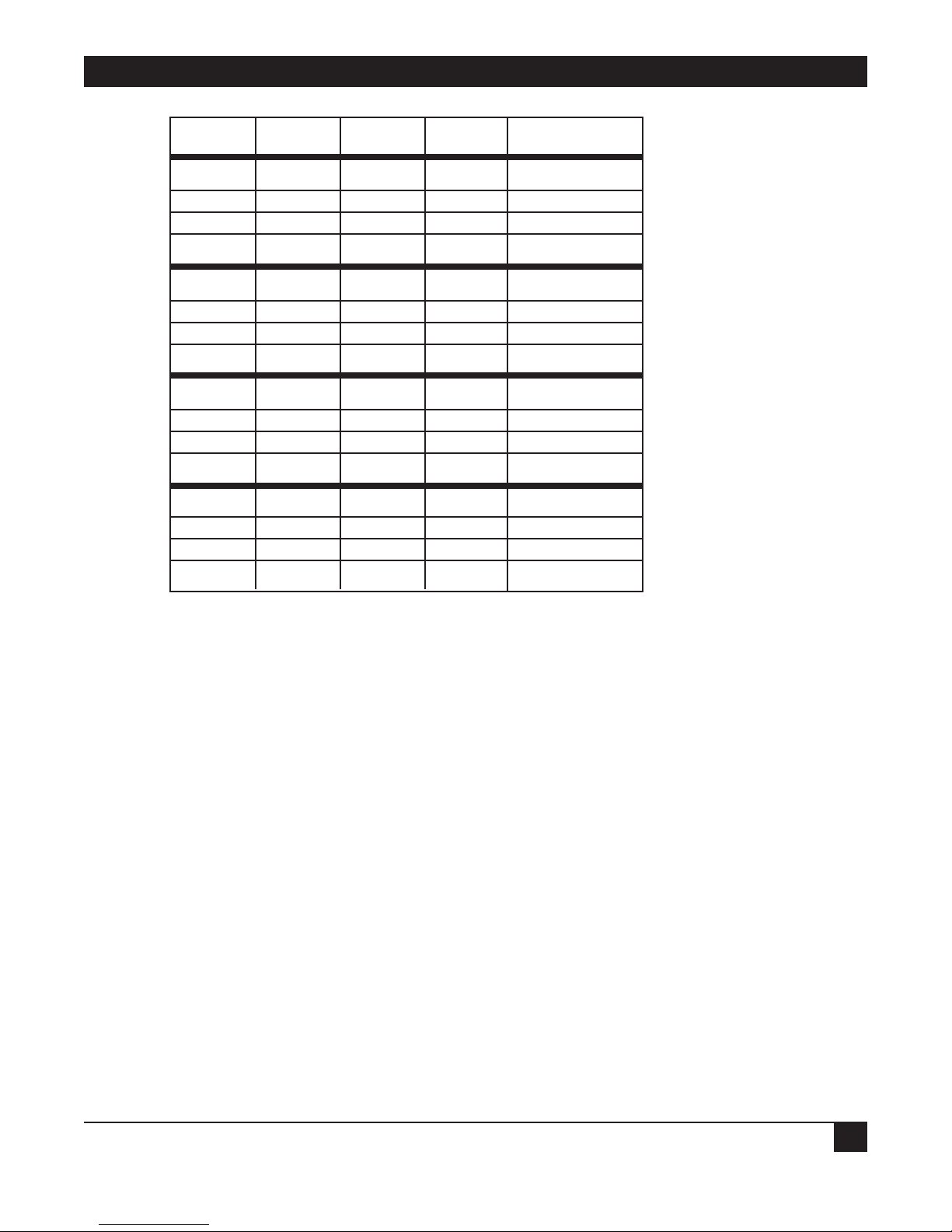
7, 8, 9 and 10 - Set up terminal baud rate, if speed detection is turned off.
Page 14
CHAPTER 4: Switches
13
7 8 9 10 BAUD RATE
ON ON ON ON 50
ON ON ON OFF 75
ON ON OFF ON 110
ON ON OFF OFF 134.5
ON OFF ON ON 150
ON OFF ON OFF 300
ON OFF OFF ON 600
ON OFF OFF OFF 1200
OFF ON ON ON 1800
OFF ON ON OFF 2000
OFF ON OFF ON 2400
OFF ON OFF OFF 3600
OF OFF ON ON 4800
OFF OFF ON OFF 7200
OFF OFF OFF ON 9600
OFF OFF OFF OFF 19.2K
Page 15
PROTOCOL CONVERTER MODEL A/S-4
14
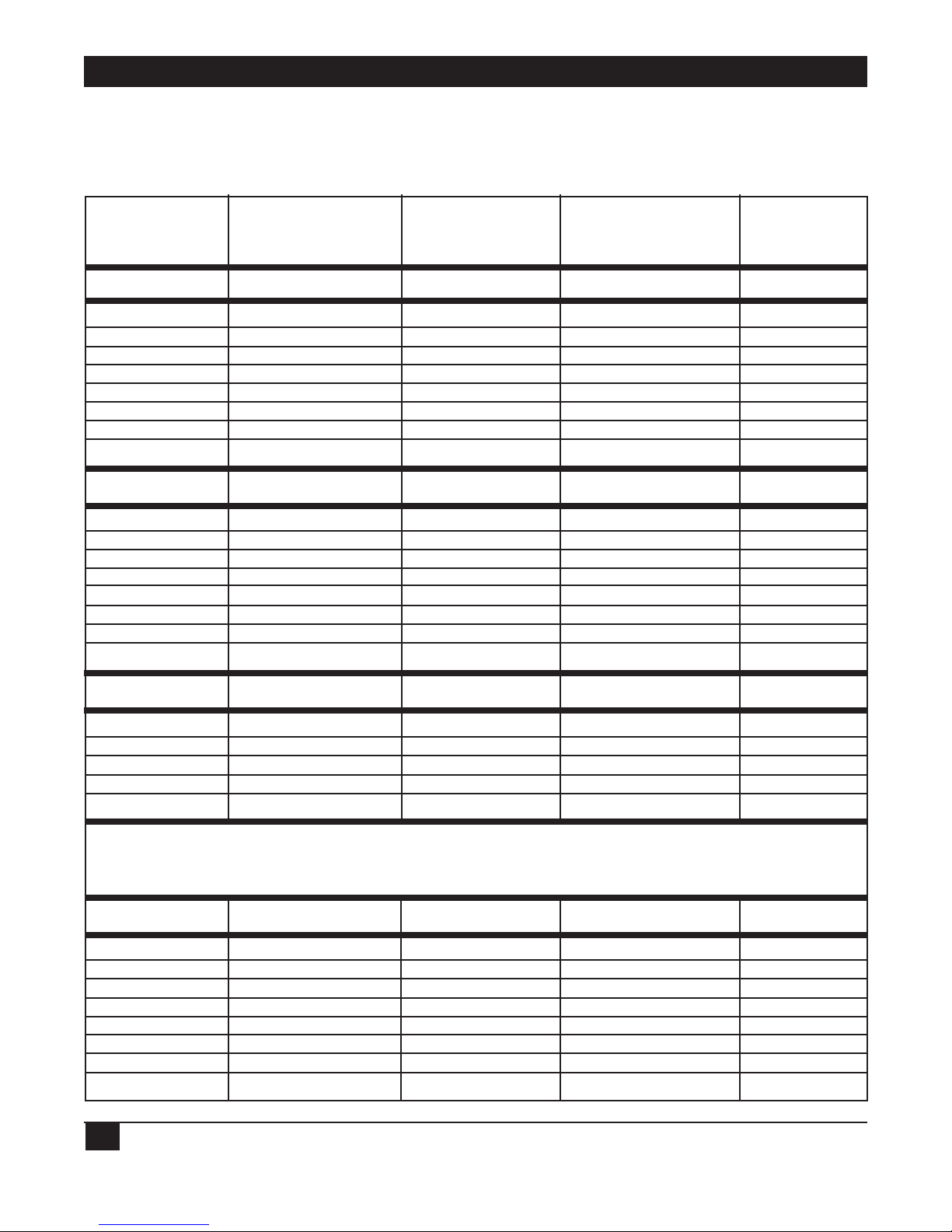
4.2 How to Set Terminal Port Switches for Different Devices
DEVICES
VDU or Async Modem Centronics Tally printer “Y” VDU,
DTE or DCE device Printer Data Products Printer
(Busy on 20) (Busy on 19) Cable
Switch 2 Switch 2 Switch 2 Switch 2 Switch 2
1 OFF 1 OFF 1 OFF 1 OFF 1 OFF
2 OFF 2 ON 2 OFF 2 OFF 2 OFF
3 OFF 3 OFF 3 OFF 3 OFF 3 ON
4 OFF 4 OFF 4 OFF 4 ON 4 OFF
5 ON 5 OFF 5 ON 5 OFF 5 OFF
6 ON 6 ON 6 ON 6 ON 6 OFF
7 ON 7 ON 7 ON 7 ON 7 OFF
8 OFF 8 OFF 8 OFF 8 OFF 8 OFF
Switch 3 Switch 3 Switch 3 Switch 3
1 OFF 1 ON 1 OFF 1 OFF
2 ON 2 OFF 2 ON 2 ON
3 ON 3 OFF 3 ON 3 ON
4 OFF 4 ON 4 OFF 4 OFF
5 OFF 5 ON 5 ON 5 OFF
6 ON 6 OFF 6 OFF 6 ON
7 OFF 7 OFF 7 OFF 7 OFF
8 OFF 8 OFF 8 OFF 8 OFF
Switch 6 Switch 6 Switch 6 Switch 6
1 ON 1 ON 1 ON 1 ON
2 OFF 2 OFF 2 OFF 2 OFF
3 ON 3 ON 3 ON 3 ON
4 OFF 4 ON 4 OFF 4 OFF
5 ON 5 OFF 5 ON 5 ON
OKIDATA
Products
(Busy on 11)
Switch 2 Switch 8
1 OFF 9 ON
2 OFF 10 ON
3 ON
4 OFF
5 OFF
6 ON Switch 9
7 ON
8 OFF 4 OFF
Page 16

CHAPTER 4: Switches
15
SW6/ 7 8 9 10 BAUD RATE
ON ON ON ON 50
ON ON ON OFF 75
ON ON OFF ON 110
ON ON OFF OFF 134.5
ON OFF ON ON 150
ON OFF ON OFF 300
ON OFF OFF ON 600
ON OFF OFF OFF 1200
OFF ON ON ON 1800 NOTE: Baud Rate
OFF ON ON OFF 2000 selection has no
OFF ON OFF ON 2400 effect if Terminal
OFF ON OFF OFF 3600 Speed Detect is
selected.
OFF OFF ON ON 4800
OFF OFF ON OFF 7200
OFF OFF OFF ON 9600
OFF OFF OFF OFF 19.2K
4.3 Modem Switches
Modem port switches for Female DB25 Modem Connector
Switch Bank S4, Switch:
1-On connects pin 4 of connector to A/S-4’s input of
CLEAR-TO-SEND
2-On connects pin 5 of connector to A/S-4’s input of
CLEAR-TO-SEND, for attaching DCE devices
3-On connects pins 25 on both terminal and modem connectors
to +5 volts DC.
4-On connects pin 19 of connector to A/S-4’s input of
CLEAR-TO-SEND, for printers with busy on pin 19
5-On connects pin 20 of the connector to A/S-4’s input
of CLEAR-TO-SEND, for devices with busy on pin 20
6-On connects pin 6 of connector to A/S-4’s input of
CARRIER DETECT
7-On connects pin 8 of connector to A/S-4’s input of
CARRIER DETECT
8-On connects pin 15 of connector to A/S-4’s input of
Transmit Clock for synchronous operation
Page 17

PROTOCOL CONVERTER MODEL A/S-4
16
Switch Bank S5, Switch:
1-On connects pin 2 of connector to A/S-4’s output of
Transmit Data, for attaching DCE devices
2-On connects pin 3 of connector to A/S-4’s output of
Transmit Data, for attaching DTE devices
3-On connects pin 2 of connector to A/S-4’s input of
Receive Data, for attaching DTE devices
4-On connects pin 3 of connector to A/S-4’s input of
Receive Data, for attaching DCE devices
5-On connects pin 4 of connector to A/S-4’s output of
REQUEST-TO-SEND, for attaching DCE devices
6-On connects pin 5 of connector to A/S-4’s output of
REQUEST-TO-SEND
7-On connects A/S-4’s REQUEST-TO-SEND to A/S-4’s
CLEAR-TO-SEND so that no external signals are needed.
Used for Burroughs TDI and non-hardware throttle devices
8-On connects pins 4 and 5 of connector so external devices
throttle itself
Switch Bank S7, Switch:
1-On supplies internal clocking for A/S-4’s input of
Transmit Clock
2-On connects pin 17 of connector to A/S-4’s input of
Receive Clock, for synchronous operation
3-On supplies internal clocking for A/S-4’s input of Receive Clock
4-On connects pin 20 of connector to A/S-4’s output of
DATA-TERMINAL-READY, for attaching DCE devices
5-On connects pin 20 of connector to A/S-4’s input of
CARRIER DETECT
6-On supplies 1X clock for internal modem port use
7, 8, 9 and 10 reserved
Switch Bank S6, Switch:
6-On supplies 16X clock for internal modem port use, for synchronization of synchronous data over
async modems
Page 18
CHAPTER 4: Switches
17
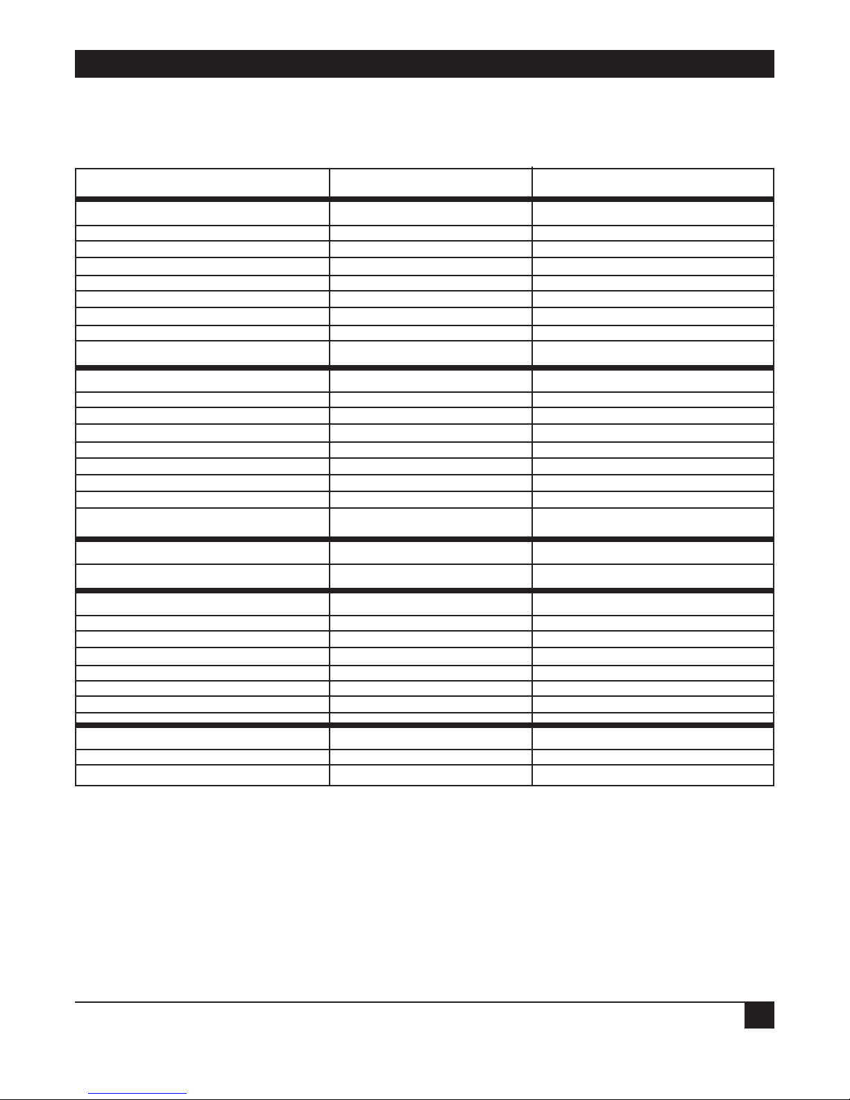
4.4 How to Set Modem Port Switches for Different Devices
DEVICES
ASYNC MODEM SYNC MODEM FRONT END PROCESSOR
Switch 4 Switch 4 Switch 4
1 OFF 1 OFF 1 OFF
2 ON 2 ON 2 OFF
3 OFF 3 OFF 3 OFF
4 OFF 4 OFF 4 OFF
5 OFF 5 OFF 5 ON
6 ON 6 ON 6 ON
7 OFF 7 OFF 7 ON
8 OFF 8 ON 8 ON
Switch 5 Switch 5 Switch 5
1 ON 1 ON 1 OFF
2 OFF 2 OFF 2 ON
3 OFF 3 OFF 3 ON
4 ON 4 ON 4 OFF
5 ON 5 ON 5 OFF
6 OFF 6 OFF 6 OFF
7 OFF 7 OFF 7 OFF
8 OFF 8 OFF 8 ON
Switch 6 Switch 6 Switch 6
6 ON 6 OFF 6 ON
Switch 7 Switch 7 Switch 7
1 ON 1 OFF 1 ON
2 OFF 2 ON 2 ON
3 ON 3 OFF 3 ON
4 ON 4 ON 4 OFF
5 OFF 5 OFF 5 ON
6 OFF 6 OFF 6 OFF
Switch 9 Switch 9 Switch 9
9 OFF 9 OFF 9 OFF
10 OFF 10 OFF 10 OFF
NOTE
Modem port baud rate is selected byH- application options menu.
Page 19

PROTOCOL CONVERTER MODEL A/S-4
18
4.5 Option Switches
Switch Bank S8, Switch:
1-RESERVED
2-RESERVED
3-RESERVED
4-RESERVED
5-RESERVED
6-RESERVED
7-RESERVED
8-RESERVED
9-On connects pins 9 on both terminal and modem connectors to +10 Volts DC.
10-On connects pins 10 on both terminal and modem connectors to -10 Volts DC.
Switch Bank S9, Switch:
Switch Switch Setting
Number Function ON OFF
1 Terminal Port Data Bits * 7 8
2 Reset Default Options on Reset NO YES
3 Single or Multi LU Multi Single
4 VDU/Printer “Y” Interface * Disable Enable
5 Terminal Speed Detection DISABLE ENABLE *
6 Option Change on Power Up * YES NO
7 Terminal Parity Type Odd Even *
8 Terminal Parity DISABLE ENABLE *
9 TDI Transmit ENABLE DISABLE
10 TDI Receive ENABLE DISABLE *
* = Factory Setting
Page 20

CHAPTER 5: LED Indicator
19
5. LED Indicator
The front of A/S-4 enclosure provides 10 light emitting diodes (LED) indicators. The indicators are
arranged and labeled in the following order, from left to right.
TTX Terminal Transmit Data
TRX Terminal Receive Data
TCD Terminal Carrier Detect
TCTS Terminal Clear To Send
ERROR Error Condition
POWER Power On
MCTS Modem Clear to Send
MCD Modem Carrier Detect
MRX Modem Receive Data
MTX Modem Transmit Data
TTX Flashes as data is transmitted by the A/S-4 out the terminal port.
TRX Flashes as data is received by the A/S-4 from the terminal port.
TCD Lights when the A/S-4’s input of Carrier Detect is high on the terminal port. This light
must be on while TRX is flashing for A/S-4 to process received data.
TCTS Lights when the A/S-4’s input of Clear to Send is high on the terminal port. This light
must be on for the A/S-4 to transmit data on the terminal port.
ERROR Error Condition Exists - Memory error, bad received block check, or buffer overflow.
POWER Lights when the A/S-4 is plugged in and the +5 Volt power supply is ok.
MCTS Lights when the A/S-4’s input of Clear to Send is high on the modem port. This light
must be on for the A/S-4 to transmit data on the modem port.
MCD Lights when the A/S-4’s input of Carrier Detect is high on the modem port. This light
must be on while the MRX is flashing for the A/S-4 to process received data
MRX Flashes as data is received by the A/S-4 from the modem port.
MTX Flashes as data is transmitted by the A/S-4 out the modem port.
Page 21

PROTOCOL CONVERTER MODEL A/S-4
20
6. Power Up and Configuration
Menu Operations
The A/S-4 unit options are mainly set by the operator through the
use of menus. The A/S-4 provides a very flexible package of options so to allow any VDU to operate like
an IBM 3278 terminal and an IBM 3287 printer or a 3770 work station. Because of the great numbers of
options provided, it may take a little time to set up to A/S-4 unit, but once complete, the options need
not be set up again. All options are battery protected for when the unit is turned off.
6.1 Power Up
To start installing your A/S-4 unit only the VDU need be connected. Connect to VDU, making sure all
the following steps have been followed.
1. Plug in, turn on, boot, or perform any other needed operation to ready the VDU.
2. Set switches SW2, SW3, SW6 on A/S-4 for type of VDU connecting to, see Section 4.2 How to set
Terminal Switches for different devices. The factory default switch settings are for a VDU DTE device.
3. Set SW9 for communication options needed, refer to Section 4.5 Option Switches. The factory
default switch settings are for 7 data bits, speed detection ON, menu operation ON, even parity. Be
sure that SW9/6 is in the ON position: Option change on power up enabled.
4. Plug the power transformer into any standard 110 volt AC power outlet. Plug the connector on the
other end of the power cord into the mating connector on the back of the unit. Insert the connector
so the small beveled lip faces up for ease of insertion. The beveled lip can be inserted up or down
and the unit will work fine with no harm to the A/S-4. A substitute transformer may be ordered for
the A/S-4 unit for 220 volts AC or other voltages.
5. Plug an RS232-C cable from the VDU into the terminal connector on the back of the A/S-4. Pins 2-8
and 20 are required.
6. Plug an RS232-C cable from the modem or IBM host into the modem connector. Pins 2-8, 15, 17 and
20 are required.
After the above procedure has been completed, the A/S-4 should have three lights on, the power, TCTS,
and TCD. If these lights are not all on the A/S-4 unit will not communicate with the VDU host properly.
Refer to Section 11.0 Trouble Shooting Problems and Odd Installation Problems if all three lights will
not come on.
With all three lights on, the A/S-4 is waiting for the letter “S” from the VDU for auto speed detection if
the option is enabled. The operator types lower or upper case “S” and the A/S-4 will calculate the baud
rate and send out a power up message. The A/S-4 is capable of detecting baud rates of 300, 1200, 1800,
2400, 4800 and 9600. If the speed detect option is off, the A/S-4 will send out the power up message two
or three seconds after the three lights come on at the baud rate set by switches SW6 (refer to Section 4.1
Terminal Switches). If the power up message does not look like Figure 1, check the option switch SW9
or refer to Section 13.0 Trouble Shooting Problems and Odd Installation Problems. If the message
“MEMORY ERROR U13 or U14” is displayed, refer to section 13 to determine if the A/S-4 is defective.
Page 22

CHAPTER 6: Power Up and Configuration Menu Options
21
6.2 Power Up Message
The A/S-4 sends out the message in Figure 1 on power up or the raising of DTR (DATA TERMINAL
READY) on the terminal device. This message informs the operator that the A/S-4 is ready to try to
match the operator’s terminal or terminal emulation package with the VDU (VISUAL DISPLAY UNIT)
list in the memory. The operator may now type the “HOME” key on his/her terminal so that the A/S-4
may match the VDU device with the internal VDU list so that the clear screen, home cursor, position
cursor commands, etc. to the VDU will be correct. If no match occurs, the A/S-4 defaults to the IBM
3101 VDU command set. This is not a problem if your VDU is not an IBM 3101, as you may change the
VDU by the use of menus. If your terminal does not have a home key, you may hit the space bar and set
up the VDU by the menus. Hitting the space bar leaves the internal VDU the same as the last VDU used
with the A/S-4. After typing “space” or “HOME” the A/S-4 will output the A/S-4’s main menu. If a VDU
match did occur, the screen will clear before the main menu is displayed, otherwise the VDU device will
scroll.
A/S-4
Type Home for VDU Match or Space
(version 01-030986)
Figure 1
The version number in Figure 1 reveals the current firmware level executing in the A/S-4. In this
example the firmware is level 1 of program on date 3/03/86.
Page 23

PROTOCOL CONVERTER MODEL A/S-4
22
6.3 A/S-4 Main Menu
A set of menus are used to configure the A/S-4’s options so that it will operate properly with the
particular VDU and host to which it is connected. In order to access these menus, SW9/6 must be in the
ON position (see Section 4.5). All options are stored in battery-protected RAM so that they need not be
reconfigured in the event of interruption of AC power to the unit.
At the beginning of every A/S-4 menu are the current main three options, the application, VDU and
keyboard. The application option informs you of which keyboard layout the A/S-4 will use when
running SDLC/SNA.
The A/S-4 Main Menu is shown in Figure 2. This menu coordinates the changing of the many A/S-4
options into main categories, VDU Selection, VDU commands, VDU video commands, keyboard
selection, keys on keyboard arrangement, application, application options, printer options and
verification of switch settings.
CURRENT:
Application = SDLC/SNA 3274/76 Interactive
VDU = ANSI STD; DEC VT100; Teletype 5410, 5420; Televideo 970, 960
Keyboard = Standard
PROTOCOL CONVERTER MAIN MENU
A-RUN (NO CHANGES)
ELSE CHANGE :
B-VDU
C-VDU Commands
D-VDU Video Commands
E-Keyboard
F-Keys arrangement
G-Application
H-Application Options
I-Printer Options
J-Verify Switch Settings
K-Reload Default Options
Enter Letter:
Figure 2
Page 24

CHAPTER 6: Power Up and Configuration Menu Options
23
The input allowed at this menu is one letter A thru J so to run or change an option. Listed below is a
brief description of what each letter gives you access to, refer to the section listed for more details.
Letter Section Description
A 6.4 Run A/S-4 as options are currently set.
B 6.5 Change internal A/S-4 VDU type to
match terminal device. Changes table
of VDU video commands used by A/S-4.
C 6.6 Change commands sent to VDU to
perform functions like Home, Clear, etc.
D 6.7 Turn on or off video. Also change video
commands.
E 6.8 Change to different type keyboard
arrangements.
F 6.9 Arrange keys in desired order
on keyboard.
G 6.10 Change between applications,
Interactive or Batch mode of
data transfer.
I 6.12 Printer Options
J 6.13 Verify switch settings
K 6.14 Set all A/S-4 options to default values.
6.4 Switching from A/S-4’s Main Menu to Running the Application
Once all operating parameters have been configured properly, the A/S-4 is ready to run. To connect the
asynchronous devices to the application, enter the letter “A” for the RUN option of the A/S-4’s Main
Menu. The A/S-4 will then proceed to connect up to the application in one of the following manners
depending on which of the three states the host communication line is in:
1. Modem not ready; if the modem is turned off or on a dial up line the modem has not been
dialed or on a lease line the line is down, the A/S-4 will display on the VDU “DIAL UP SDLC
LINE”. Once the phone line connection with the host has been establish the A/S-4 will
proceed to one of the following two states. Refer to Section 13.0 on Trouble Shooting if the
Dial Up message will not go away for more information.
Page 25

PROTOCOL CONVERTER MODEL A/S-4
24
2. Modem connected to host but LU inactive; if the LU is inactive the A/S-4 will display
“WAITING FOR LU TO COME ACTIVE”. The LU should come active after a few seconds
of this message appearing on the VDU. If the LU does not come active, then one of the
following problems may exist:
A. Host is not polling PU (Physical Unit) Solution: Have a network operator activate
the PU and maybe the line also.
B. PU address (or station address) is incorrect Solution: Return to A/S-4 menus and
change PU address.
C. LU address is incorrect Solution: Return to A/S-4 menus and change LU address.
After the LU comes Active, the A/S-4 will proceed to the following state. Refer to Section 13.0 on
Trouble Shooting if the LU will not activate for more information.
NOTE
In states 1 and 2 typing any key will return A/S-4 to it’s Main Menu
3. Application running:
Interactive - The A/S-4 will refresh the VDU’s screen with the last screen received from the
host (which could be blank). Operation will then function as a 3278 CRT.
Batch - The A/S-4 will display the status of the LU on the status line but no previous data from
the system will be displayed on the VDU. Operation will then function as a 3770 work station.
Page 26

CHAPTER 6: Power Up and Configuration Menu Options
25
6.5 Changing the VDU Type
If the current VDU type displayed at the top of the A/S-4 Main Menu does not match the VDU or VDU
emulation package you have connected to the A/S-4, you may change the VDU type by entering the
letter “B” in response to the Main Menu. The change VDU Menu will then be displayed on your screen
as in Figure 3. If your screen is scrolling A/S-4 menus instead of clearing the screen before each menu,
then you should change the VDU type. The change VDU menu allows you to match your VDU with one
of the A/S-4’s fixed VDU types or to create a new A/S-4 VDU type. The A/S-4 feature for creating a new
VDU type allows A/S-4 to work with any asynchronous device with screen capabilities.
CURRENT:
Application = SDLC/SNA 3274/76 Interactive
VDU = ANSI STD; DEC VT100; Teletype 5410, 5420; Televideo 970, 960
Keyboard = Standard
Change: VDU
1 or A-Exit
2-Change Current Name
3-Add Name
4-Delete
PROGRAMMABLE: FIXED:
A- F-IBM 3101; DEC VT52
B- G-ANSI STD: DEC VT100; Teletype 5410,5420; Televideo 970,960
C- H-Televideo 910 thru 950; Zentec Zephyr
D- I-Lear Siegler ADM3A
E- J-IBM PC 3270
Enter Number:
Figure 3
The change VDU menu allows 4 operations as described below:
1. Exit - By entering the number 1 or the letter A the A/S-4 will return to the Main Menu with
the VDU type currently at the top of the screen.
2. Change current VDU type at top of screen - By entering the number 2, the operator may
change the VDU type. The A/S-4 will then display “ENTER LETTER:” so that the operator
may select the letter preceding the desired VDU type from the list of programmable and
fixed VDU types. Fixed VDU types have the VDU commands characters hard coded into
the A/S-4’s firmware and require that your VDU or VDU emulator match those commands
character for character. Programmable VDU types have VDU command characters stored in
battery protected memory so that command characters in the A/S-4 can be changed to match
the operator VDU or VDU emulator that is not exactly like any of the Fixed VDU types.
After the operator enters the desired letter (A thru J), the menu will redisplay with the new
VDU type at the top of the screen using the new command character set of the selected VDU.
Page 27

PROTOCOL CONVERTER MODEL A/S-4
26
NOTE
Selection of a blank programmable VDU type may cause erroneous command
characters to be sent to the operators VDU. The programmable VDU type should be
added by option 3 before it is selected.
3. Add or Change Name - by entering a 3 the operator is able to add a name to or change a
name from the “PROGRAMMABLE” column see figure 4. This is done when the operator’s
VDU does not match one of the “FIXED” VDU’s and it allows him to define to the A/S-4 the
various commands his VDU needs to operate properly (e.g., the command from the A/S-4
which will cause his VDU to clear the screen). In the example shown in figure 4, the operator
has given the name “NEW VDU” to VDU A. Operator input is underlined. The 10 characters
are filled out with spaces or just type carriage return. By typing the letter “H”, he has copied
the characteristics of VDU H into those of “NEW VDU”. The “CURRENT” header will now
show the VDU as “NEW VDU”. Using the VDU commands menu (selection C on the Main
Menu) he can now change the clear screen command (or any other command) from the
command copied from VDU H to whatever “NEW VDU” needs (these commands may be
found in the NEW VDU manual).
4. Delete Name - By entering a 4 the operator can delete a name from the “PROGRAMMABLE”
VDU list.
Enter Number: 3 Enter Letter A
Enter A 10 Character Name: NEW VDU
Make New NEW VDU Name Look like established Name: (Enter Letter) H
CURRENT:
Application = SDLC/SNA 3274/76 Interactive
VDU = NEW VDU
Keyboard = Standard
Change: VDU
1 or A-Exit
2-Change Current Name
3-Add or Change Name
4-Delete
PROGRAMMABLE: FIXED
A-NEW VDU F-IBM 3101; DEC VT52
B- G-ANSI STD; DEC VT100; Teletype 5410, 5420; Televideo 970, 960
C- H-Televideo 910 thru 950; Zwntec Zepher
D- I-Lear Siegler AND 3A
E- J-IBM PC 3270
Figure 4
Page 28

CHAPTER 6: Power Up and Configuration Menu Options
27
6.6 Changing VDU Commands for the VDU Type Selected
By selecting item C from the main menu (Section 6.3), the operator obtains the menu shown in figure 5.
Items from this menu can only be changed for programmable VDUs. This menu allows you to define
the video commands our VDU expects. You should consult your VDU users manual to determine what
the command characters are for the various VDU functions.
CURRENT:
Application = SDLC/SNA 3274/76 Interactive
VDU = NEW VDU
Keyboard = STANDARD
Change CMD VDU Responds to for:
A-Exit
B-ESC VDU CMD to Follow (Set up 1st!!!)
C-ESC ` Data to Printer: ON
D-ESC a Data to Printer: OFF
E-ESC ` Data to Card: ON
F-ESC a Data to Card: OFF
G-ESC ` Data to Disk: ON
H-ESC a Data to Disk: OFF
I-ESC * Clear Screen
J-CTL ^ Home
K-ESC = Cursor Position: Start Char
L- Row Offset Value
M-CTL @ Row/Col Separator
N- Column Offset Value
O-CTL @ Final Char
P-NO Decimal Row/Col Values
Enter Letter:
Figure 5
Figure 6 gives an example of how the operator would enter a new Home Cursor command to match his
VDU. Operator input is underlined.
Enter Letter: J Enter CMD: CTL Y
Figure 6
To disable the two character Printer, Card or Disk on/off command, enter a space for the command,
also use a space to terminate the command.
Page 29

PROTOCOL CONVERTER MODEL A/S-4
28
6.7 Changing Video Attributes and Commands for VDU
The menu obtained by selecting item D of the main menu is shown in Figure 7. This menu allows the
operator to define the parameters which will give the proper video highlighting to the fields on the VDU
screen.
CURRENT:
Application = SDLC/SNA 3274/76 Interactive
VDU = NEW VDU
Keyboard = STANDARD
Cmd chars for different VDU video displays for different type fields
A-Exit
B-Start of video cmd: CTL [
C-End of video cmd:
D-Video cmd takes up a space on VDU?N
Middle of cmd: For Data Type of:
E-(=UNPROTECTED, ALPHANUMERIC, LOW INTENSITY
F-(=UNPROTECTED, ALPHANUMERIC, HIGH INTENSITY
G-(=UNPROTECTED, NUMERIC, LOW INTENSITY
H-(=UNPROTECTED, NUMERIC, HIGH INTENSITY
I-)=PROTECTED, ALPHANUMERIC, LOW INTENSITY
J-)=PROTECTED, ALPHANUMERIC, HIGH INTENSITY
K-)=PROTECTED, NUMERIC, LOW INTENSITY
L-)=PROTECTED, NUMERIC, HIGH INTENSITY
M-(=NONDISPLAY & NONPRINT
Enter Letter:
Figure 7
The host CPU can send commands to its terminals to define how the video display will be printed. An
example is a display using highlighted areas for data entry. The A/S-4 can perform this type of display
presentation for almost any terminal. In operation the A/S-4 intercepts the host video commands and
translates them into the commands that the attached VDU needs to perform the function.
If you are using special displays then you must use selections B, C and D to set up your display attributes.
Consult your VDU users manual to determine which characters are used to create the type display you
need and enter those characters in the fields as needed.
Page 30

CHAPTER 6: Power Up and Configuration Menu Options
29
The general format of a video command to a VDU is as follows:
ESC X Y Z
Start of video cmd.
Middle of video cmd.
nd of video cmd.
X, Y and Z represent ASCII characters. The end of video command may not be necessary and therefore
displayed as a blank. Items B, C and E through M can be defined using the format shown above.
Item D differentiates between two techniques of video highlighting: 1) The video command occupies a
space on the screen and defines the start of a video highlight field (e.g., Televideo 925). 2) The video
command does not occupy a space and does determine the type of video highlight for all subsequent
received characters, regardless of their positions on the screen (e.g., DEC VT100).
Video types referred to in figure 7 correspond to the video highlighting codes which are sent to the A/S4 from the IBM host. It is up to the operator to enter the proper value for the middle
of command to match (or mismatch, if desired) each video type.
If no video highlighting is desired, the operator may turn off (prevent the A/S-4 from sending video
commands) this feature by entering a space for Item B, start of video command. The A/S-4 assumes if
there is no start command, than there is no video commands for the VDU.
Page 31

PROTOCOL CONVERTER MODEL A/S-4
30
A/S-4 Standard Keyboard Layout
ESC ! 1 @ 2 # 3 $ 4 % 5 ^ 6 & 7 * 8 ( 9 )0 _ - + =
DEL
LINE
TAB Q W E R T Y U I O P { [ } ] RETURN
PFI PF2 PF3 PF4 PF5 PF6 PF7 PF8 PF9 PF10
DISC FIELD DUP UP HOME CUR
VDC MARK ARROW SEL
CTRL LOCK A S D F G H J K L : ; " ' | \
PF11 PF12 PF13 PF14 PF15 PF16 PF17 PF18 PF19 PF20
DUAL LOCAL PRINT NEW
MONO PRINT LINE
SHIFT Z X C V B N M , . ? / SHIFT
PF21 PF22 PF23 PF24 PA1 PA2 PA3 IDENT CENT
RESTR DISC DISC RE DOWN ENTER
SNAP SDLC VDU DSPLY ARROW
SPACE BAR
BOLD PRINT = CONTROL CMDS
NORMAL PRINT = ESCAPE CMDS
Page 32

CHAPTER 6: Power Up and Configuration Menu Options
31
IBM PC Keyboard Layout
~ ` ! 1 @ 2 # 3 $ 4 % 5 -- 6 & 7 * 8 ( 9 ) 0 _ - + =
PF1 PF2 PF3 PF4 PF5 PF6 PF7 PF8 PF9 PF10 PF11 PF12
QWE RTYU I OP! |
Page 33

PROTOCOL CONVERTER MODEL A/S-4
32
ADM 1178 Keyboard Layout
Page 34

CHAPTER 6: Power Up and Configuration Menu Options
33
IBM 3101 Keyboard Layout
Page 35

PROTOCOL CONVERTER MODEL A/S-4
34
PNS Keyboard Layout
Page 36

CHAPTER 6: Power Up and Configuration Menu Options
35
6.8 Changing Keyboard Layout Type
By selecting E from the main menu, the menu shown in Figure 8 is obtained. This is used to select the
specific keyboard mapping the operator desires. Selection of F, G and H provide fixed keyboards shown
on the previous pages. Programmable keyboards may be added as any of the selections A through E. By
using a programmable selection, the operator can design the keyboard to his or her liking.
To change the keyboard used enter 2 then select the keyboard layout you desire from those listed.
If you prefer an unlisted keyboard type you should select one of the letters under programmable and
enter the name (10 characters max). If the name is less than ten characters long, type carriage return or
spaces to complete the ten character name. If your keyboard looks like one of the fixed keyboards then
you should enter its letter as a response to “make new keyboard look like established name”.
NOTE
Selection of a blank entry from the programmable list may cause the A/S-4 to
malfunction.
Names of programmable keyboards may be added, changed, or deleted by using selection 3 and 4.
If a programmable keyboard has been selected, the operator should now set up the keys arrangement as
he or she wishes using selection F from the A/S-4’s main menu.
CURRENT:
Application = SDLC/SNA 3274/76 Interactive
VDU = ANSI STD; DEC VT100; Teletype 5410, 5420; Televideo 970, 960
Keyboard = Standard
Change: Keyboard
1 or A-Exit
2-Change Current Name
3-Add Name
4-Delete
PROGRAMMABLE: FIXED:
A- F-STANDARD
B- G-IBM PC 3270
C- H-ADM 1178
D- I-IBM 3101
E- J-PNS
Enter Number:
Figure 8
Page 37

PROTOCOL CONVERTER MODEL A/S-4
36
6.9 Changing Keys Arrangements on a Particular Keyboard Layout Type
Selection of item F from the main menu will cause the menu shown in Figure 9 to be displayed.
CURRENT:
Application = SDLC/SNA 3274/76 Interactive
VDU = ANSI STD; DEC VT100; Teletype 5410, 5420; Televideo 970, 960
Keyboard = STANDARD
A-Exit
B-PF Keys
C-PA Keys
D-Command Keys
E-IBM Keys
F-PROTOCOL CONVERTER Keys
Enter Letter:
Figure 9
This menu allows for great flexibility in keyboard layouts. If you desire you may alter Key assignments or
design your own keyboard layout. The selections available from this menu is as follows:
Exit Go back to main menu
PF Keys Programmable function keys
PA Keys Programmable attention keys
Command Keys Keys used for editing & cursor movement (e.g., Clear)
IBM Keys Keys used to perform IBM terminal operations (e.g., Field Mark)
Protocol Keys used to control the A/S-4’s operation
Converter Keys (e.g., Restart A/S-4, which will take operator back to main menu)
The keys arrangement can only be changed if the current keyboard is a programmable keyboard (see
Section 6.8)
Page 38

CHAPTER 6: Power Up and Configuration Menu Options
37
6.9.1 PF KEYS
Selection of item B from the menu shown in Figure 9 will cause the menu shown in Figure 10 to be
displayed.
If the operator wants to use a different key for PF2, he would first enter the letter “C” and then enter the
new value(s) in response to prompt(S) for the new value(s). The key sequences entered for the PF keys
must be either control or escape sequences to work properly, and any specific key sequence must be
entered for only one key. After a new value has been entered, the menu will be redisplayed and will
show the new value(s).
CURRENT:
Application = SDLC/SNA 3274/76 Interactive
VDU = ANSI STD; DEC VT100; Teletype 5410, 5420; Televdeo 970, 960
Keyboard = STANDARD
Change: PF Keys (Keys Typed on VDU to Perform Function)
A-Exit B-ESC Q or ESC q=PF1
C-ESC W or ESC w=PF2 D-ESC E or ESC e=PF3
E-ESC R or ESC r=PF4 F-ESC T or ESC t=PF5
G-ESC Y or ESC y=PF6 H-ESC U or ESC u=PF7
I-ESC I or ESC i=PF8 J-ESC O or ESC o=PF9
K-ESC P or ESC P=OF10 L-ESC A or ESC a=PF11
M-ESC S or ESC S=PF12 N-ESC D or ESC d=PF13
O-ESC F or ESC f=PF14 P-ESC G or ESC g=PF15
Q-ESC H or ESC h=PF16 R-ESC J or ESC j=PF17
S-ESC K or ESC k=PF18 T-ESC L or ESC l=PF19
U-ESC ; or =PF20 V-ESC Z or ESC z=PF21
W-ESC X or ESC x=Pf22 X-ESC C or ESC c=PF23
Y-ESC V or ESC v=PF24
Enter Letter:
Figure 10
Page 39

PROTOCOL CONVERTER MODEL A/S-4
38
6.9.2 PA KEYS
Selection of item C from the menu shown in figures 9 will cause the menu shown in figure 11 to be
displayed. Keys changes are performed in the same manner as the PF key changes.
CURRENT:
Application = SDLC/SNA 3274/76 interactive
VDU = ANSI STD; DEC VT100; Teletype 5410, 5420; Televideo 970, 960
Keyboard = STANDARD
Change: PA Keys (Keys Typed on VDU to Perform Function)
A-Exit B-ESC B or ESC b=PA1
C-ESC N or ESC n=PA2 D-ESC M or ESC m=PA3
Enter Letter:
Figure 11
6.9.3 COMMAND KEYS
Selection of item D from the menu shown if figure 9 will cause the menu shown in figure 12 to be
displayed. Key changed are performed in the same manner as the PF key changes.
CURRENT:
Application = SDLC/SNA 3274/76 Interactive
VDU = ANSI STD; DEC VT100; Teletype 5410, 5420; Televideo 970, 960
Keyboard = STANDARD
Change: Command keys (Keys Typed on VDU to Perform Function)
A-Exit B-CTL I or =Tab
C-CTL Y or =Back Tab D-CTL J or CTL J =New Line
E-CTL H or =Back Space F-CTL O or =Home
G-ESC - or =Clear H-CTL H or =Left Arrow
I-CTL G or =Left 2 Arrow J-CTL K or =Right Arrow
K-CTL L or =Right 2 Arrow L-CTL U or =Up Arrow
M-CTL N or =Down Arrow N-CTL M or =Enter (Send)
O-ESC 9 or =Attention
Enter Letter:
Figure 12
Page 40

CHAPTER 6: Power Up and Configuration Menu Options
39
6.9.4 IBM KEYS
Selection of item E from the menu shown in figure 9 will cause the menu shown in figure 13 to be
displayed. Key changes are performed in the same manner as the PF key changes.
CURRENT:
Application = SDLC/SNA 3274/76 Interactive
VDU = ANSI STD; DEC VT100; Teletype 5410, 5420; Televideo 970, 960
Keyboard = STANDARD
Change: IBM Keys (Keys on VDU to Perform Function)
A-Exit B-CTL T or =Duplicate
C-CTL R or =Field Mark D-ESC 7 or =Erase EOF
E-ESC 6 or =Erase Input F-ESC 5 or =Insert Mode
G-ESC . or =Ident H-CTL P or =Cursor Select
I-ESC M or =Device Cancel J-ESC 8 or =System Request
K-ESC 0 or =Reset
Enter Letter:
Figure 13
6.9.5 A/S-4 KEYS
Selection of item F from the menu shown in figure 9 will cause the menu shown in figure 14 to be
displayed. Key changes are performed in the same manner as the PF key changes.
CURRENT:
Application = SDLC/SNA 3274/76 Interactive
VDU = ANSI STD; DEC VT100; Teletype 5410, 5420; Televideo 970, 960
keyboard = STANDARD
Change: Protocol Converter Keys (Keys on VDU to Perform Function)
A-Exit B-CTL Z OR =Restart Protocol Converter
C-CTL C or =Disc. VDU D-CTL X or =Disc. SDLC
E-CTL A or =Dual or Mono Case F-ESC / or =Cent Key
G-CTL V or =Redisplay Screen H-CTL D or =Local Print
I-CTL F or =Stop/Start Print J-ESC 2 or =Line Insert
K-ESC l or =Line Delete L-ESC 4 or =Char Insert
M-ESC 3 or =Char Delete
Enter Letter:
Figure 14
Page 41

PROTOCOL CONVERTER MODEL A/S-4
40
The functions of the A/S-4 Keys are as follows:
Restart Protocol Jump to A/S-4’s main menu for
Converter option changes.
Disconnect VDU Causes A/S-4 to drop DTR to device connected to terminal port.
Used to disconnect a modem attached to the terminal port in a
dial-up configuration
Disconnect SDLC Causes A/S-4 to drop DTR to device connected to modem port.
Used to disconnect a modem attached to the modem port in a dialup configuration.
* Dual or Mono Case Used to shift between Dual (Upper & Lower Case) and Mono
(Upper Case only).
* Cent Key Allows cent ( ) key to be sent to IBM host since most VDU’s do not
have a cent key.
* Redisplay Screen Used to redisplay current screen. Used when VDU is attached to
terminal port through dial-up modem and garbage has been
displayed on screen.
* Local Print Print VDU screen on printer
* Stop/Start Print Allows stopping of printer to align forms and then starting again.
* Line Insert Causes a blank line to be inserted at cursor location.
* Line Delete Causes a line of data to be deleted at cursor location.
* Character Insert Causes a Null Character to be inserted at cursor location.
*Character Delete Causes a data character to be deleted at cursor location.
*Keys used only during interactive application, not used in batch.
Page 42

CHAPTER 6: Power Up and Configuration Menu Options
41
6.10 Changing Application
The A/S-4 is shipped from the factory to power up in the SDLC/SNA 3274/76 Interactive mode of
operation. The current mode of operation can be determined by looking at the top of the main menu,
as in Figure 14 (it is Interactive). To change to Batch operation, the operator types the letter G in
response to the main menu. The main menu will then be redisplayed with “SDLC/SNA 3776/7 Batch”
at the current application location on the main menu. To go back to interactive, type G again. The
current mode of operation is protected in non-volatile RAM, so that on power up it will return to the last
operating state.
6.11 Changing Application Options
Selection of item H from the main menu will cause the menu shown in Figure 15 or 16 to be displayed.
The A/S-4 is shipped from the factory to power up in the SDLC/SNA 3274/76 Interactive mode of
operation. Selection of item H from the menu shown in Figure 2 will cause the menu shown in Figure
15 to be displayed.
Figure 16 shows the application options for the A/S-4 when selected to run in the SDLC/SNA 3776/77
Batch mode.
CURRENT:
Application = SDLC/SNA 3274/76 Interactive
VDU = ANSI STD; DEC VT100; Teletype 5410, 5420; Televideo 970,960
Keyboard - STANDARD
Change: Application Options
A-Exit B-XID=018085B8
C-PU Addr=F7 D-SDLC Baud Rate=1200
E-XON/OFF=Both F-VDU LU Addr-02
G-PRT LU Addr=03 H-PRT LU Type=03
Enter Letter:
Figure 15
Page 43

PROTOCOL CONVERTER MODEL A/S-4
42
6.11.1 CHANGING INTERACTIVE APPLICATION OPTIONS
The change Application menu allows 8 operations as described below:
A. Exit - By entering the letter A the A/S-4 will return to the Main Menu.
B. XID - By entering a B the operator is able to change the A/S-4 SDLC control unit identifier. Only
hexadecimal numbers are allowed to be entered for this selection, the first two digits are fixed at 01.
The next character indicates what type of device the A/S-4 (7=3274, 8=3276, 0=3774, 1=3774P,
2=3771 and 3=3776/77).
C. PU Addr - To change the units physical unit address enter C. Only hexadecimal numbers are allowed
to be entered for this selection; addresses x’00’-SSCP address and x’FF’-Global SDLC address can not
be used.
D. SDLC Baud Rate - By entering a D the operator can select the baud rate at which the host will
transmit and receive data from the A/S-4. This selection is only used when running SDLC over
asynchronous modems or when the A/S-4 is supplying clocks to a front end processor. After entering
the letter D the current baud rate will be displayed. To change it, enter the letter Y which will scroll
pass each selectable baud rate, when the correct rate is displayed entering any key other than the Y
will save the new baud rate.
NOTE
SDLC baud rate has no effect when running with synchronous modems.
E. XON/OFF - Entering an E allows the selecting of the DC1 (XON), DC3 (XOFF) protocol on the
A/S-4’s terminal port. This protocol can be used; TO the unit or FROM the unit or in BOTH
directions. To disable the XON/OFF protocol, select the option for OFF by the use of the letter Y,
entering any key will save the selection. This protocol is used so the A/S-4 or the attached async
device will not overflow each others buffers with data. If the A/S-4 has room to store only 20
characters from the VDU, the unit will drop it’s RTS signal (can be connected to pin 4, 5, 11, 19 or 20
of EIA connector) and send an XOFF character if option is set for FROM or BOTH. When the A/S-4
is sending data to the VDU, the VDU can stop the flow by dropping it’s signal connected to the A/S4’s CTS or by sending a XOFF character, if the A/S-4’s XON/XOFF option is set for TO or BOTH.
F. VDU LU Addr - The VDU LU address can be changed by entering the letter F. For this selection only
hexadecimal numbers are allowed to be entered, from the range of X’01’ to X’FF’ but for most
installations the address range of the specific type of control unit is as follows:
IBM* 3274 = X’02’-X’21’
IBM* 3276 = X’02’-X’09’
IBM* 3776 Model 3 and 4 = X’01’-’06’
NOTE
Do not set the VDU and PRT LU addresses to the same values.
Page 44

CHAPTER 6: Power Up and Configuration Menu Options
43
G. PRT LU Addr - By entering a G the operator can select which LU’s data will go to the printer
attached to the A/S-4’s terminal port. Selection of this address is done the same as for the VDU LU
addr above.
H. PRT LU Type - The printer LU type is changed by entering the letter H which causes the LU type to
toggle between type 1 and 3. Type 3 print data is preceded with a Write command followed by a
WCC with the start printer bit set. Type 1 data doesn’t have this Write command or WCC in its data.
CURRENT:
Application = SDLC/SNA 3776/77 Batch
VDU = ANSI STD; DEC VT100; Teletype 5410, 5420; Televideo 970,960
Keyboard = STANDARD
Change: Application Options
A-Exit B-XID=01300FF
C-PU Addr=F7 D-SDLC Baud Rate=1200
E-XON/XOFF=OFF F-VDU LU Addr=01
G-PRT LU Addr=02 H-Start of File=CTL B
I-End of File=CTL C J-Send FMH-2 to VDU=NO
K-Precede TRN Ctl Chars L-Echo Input=YES
with DLE=YES
M-Card Input Data Only=YES
N-VDU Auto Logon Msg=LOGON
APPLID (SYSA) LOGMODE
(BUF512) DATA (RMT13,,,
CTL \ L163AC00CTL \)
O-PRT Auto Logon Field=L163AC01
P-VDU/PRT Auto Signon Msg=/*SIGNON
Enter Letter:
Figure 16
Page 45

PROTOCOL CONVERTER MODEL A/S-4
44
6.11.2 CHANGING BATCH APPLICATION OPTIONS
The change Application menu allows 16 operations as described below:
A thru G - are the same as for changing Interactive options, refer to section 6.11.1 for details.
H. Start of File - By entering an H the operator can select the first character that must be received from
the VDU before any data is stored and then transmitted to the host. This character is also the first
character sent to the VDU when data is received from the host. This is a single character command
that can be a control character displayed as CTL or a printable character. The Start of File character
can be disabled by setting it to a null X’00’ or space character.
I. End of File - This single character command that causes the VDU to terminate the transmission of
data to the host and is received by the VDU when an end of message, is received from the host can be
changed by entering an I. This command is selected and disabled the same as the Start of File
character described above.
J. Send FMH-2 to VDU - Option can be toggled on or off by entering the letter J. When this option is
enabled “YES” a Function Management Header-2 received from the host is sent to the VDU, for
complete details refer to Section 8.1 on Batch operation.
K. Precede TRN Ctl Chars with DLE - By entering a K, this option can be toggled on or off. This causes
transparent control characters (X`3F’ or less) received from the host to be made a printable ASCII
character by setting its two most significant bits. This character then would be preceded with a DLE
character (X`10’) before being sent to the VDU if option is set for “YES”. This option also
determines if data received from the VDU will be preceded by a DLE if the character is less than a
X`20’ space character.
L. Echo Input - By entering a L the operator can toggle this option on or off if he would like all
characters transmitted by the VDU to the A/S-4 sent back to the VDU.
M. Card Input Data Only - Option can be toggled on (“YES”) by entering an M, which would cause all
data received from the VDU to be transmitted to the host in card format by the inbound (VDU) LU.
With this option on, no device indicator should be sent to the VDU. When this option is off (“NO”),
data received from the VDU must be preceded by a device indicator which determines what device
(console, card, printer or disk) is sending the data to the host. Refer to section 8 for more
information on the device indicator. With option on, only the inbound (VDU) LU can send data to
the host so both LU’s must be set for Auto Logon to become active with the application (e.g. JES2).
Page 46

CHAPTER 6: Power Up and Configuration Menu Options
45
N. VDU Auto Logon Msg - This 80 character message can be changed by entering the letter N followed
by the Logon message, containing any printable ASCII character (X`20’-X`7F’). The field separator
(X`1C’) character, which is used to delimit the different logon strings for the VDU LU and the PRT
LU. The carriage return (X`0D’) character is used to indicate the end of the logon message. The
auto logon is enabled whenever any data is present in the logon message. To disable auto logon,
enter a carriage return as the first character of the message. This logon message will be sent to the
host by the VDU (inbound) LU when this LU becomes active. All data except the CTL\’s (field
separators) will be sent.
O. PRT Auto Logon Field - This 10 character field can be changed by entering the letter O followed by
the logon field, containing any printable ASCII character (X`20’-X`7F’). The carriage return
(X`0D’) character terminates the end of the field. This field if selected, will cause an auto logon
message to be sent by the PRT (outbound) LU when the PRT LU becomes active. The logon
message will be the same one as for the VDU LU except the data enclosed by CTL\’s will be replaced
with the PRT auto logon field. The PRT logon field is disabled by entering a carriage return as the
first character of the PRT logon field.
P. VDU/PRT Auto Signon Msg - This 80 character message can be changed by entering the letter P
followed by the signon message, containing any printable ASCII character (X`20’-X`7F’). This
carriage return (X`0D’) character terminates the signon message. This message if selected, will be
sent by the VDU LU and PRT LU to the host after a LU-to-LU session is established for the respected
LUs. Entering a carriage return as the first character of the message will disable the auto signon.
NOTE
The auto logon and signon messages cannot contain any character used only in
EBCDIC (e.g. cent character X`4A’).
6.12 Printer Options
Selection of item I from the main menu will cause the menu in Figure 17 to be displayed. This menu is
used to select default printer settings for the printer attached to the A/S-4. Selection of B, C and D are
considered programmable in that the host computer can send:
1. Set Horizontal Format (SHF) command to change the B- Column Width.
2. Set Vertical Format Density (SVF) command to change C-Lines Per Page
3. Set Line Density (SLD) command to select a different D-Lines Per Inch.
Page 47

PROTOCOL CONVERTER MODEL A/S-4
46
These new values, if received from the host would then be sent to the printer if the G-Start Char-FORMS
or K-Start Char-DENSITY are selected.
CURRENT:
Application = SDLC/SNA 3274/76 Interactive
VDU = ANSI STD; DEC VT100; Teletype 5410,5420; Televideo 970,960
Keyboard = STANDARD
Change: Printer Options
A-Exit
B-Column Width (xxx)=132
C-Lines Per Page (xxx)=066
D-Lines Per Inch (xxx)=006
E-Single/Double Space=Single
F-MONO/Dual Case = Dual
Forms Set-Up Command Sequence:
G-Start Char-FORMS=
H-Multiple - (‘xxx’ X Inches)-xxx=
I-Separator Char=CTL @
J-Final Char=CTL @
K-Start Char-DENSITY=
L-Separator Char-DENSITY=CTL @
M-Final Char-DENSITY=CTL @
Enter Letter:
Figure 17
The Printer Options menu allows 13 operations as described below:
A. Exit - By selection the letter A the A/S-4 will return to the main menu.
B. Column Width (xxx) - This value is used to define the length of a print line and can be changed by
entering the letter B, followed by any decimal number value from 001 to 255. An entry larger than
255 will set the column width to a value less than 255. The host set Horizontal Format (SHF)
command can temporarily change the column width used by the printer with the MPP (maximum
print position) value enclosed in the SHF command. This new MPP value will not be displayed in the
Column Width option. Refer to Section 8, Batch operation for more details.
C. Lines Per Page (xxx) - Indicates the number of print lines per page (page depth) and is changed by
entering the letter C, followed by any decimal number value from 001 to 255. Any entry larger than
255 will set the lines per page to a value less than 255. The host Set Vertical Format (SVF) command
can temporarily change the lines per page used by the printer with the MPL (maximum presentation
line) value enclosed in the SVF command. This new MPL value will not be displayed in Lines Per
Page option. Refer to Section 8, Batch operation for more information.
Page 48

CHAPTER 6: Power Up and Configuration Menu Options
47
D. Lines Per Inch (xxx) - By entering the letter D, followed by any decimal number from 001 to 063, the
operator can change the lines per inch (LPI) the printer will print. If a decimal value larger than
063 is entered, the LPI option will be set to a value less than 063. The host Set Line Density (SLD)
command can temporarily change the lines per inch used by the printer. This new LPI value will not
be displayed in the Lines Per Inch option. See Section 8, Batch operation for more information.
E. Single/Double Space - Option can be toggled from Single (NL x`15’ received from host send CR LF
to printer) to Double (NL x `15’ received from host send CR LF LF to the printer) line spacing.
F. MONO/Dual Case - By entering an F the operator can toggle from Dual (upper and lower case
characters sent to the printer) to MONO (only upper case characters are sent to the printer, if a lower
case character is received from the host it is converted to upper case).
The following commands are sent to the attached printer to change or set the printer for the selected
parameters:
G. Start Char-FORMS - This two character command can be changed by entering the letter G followed
by any ASCII control character (X`00’-X`20’) for the first character and any ASCII character for the
second one. Entering a space character as the first character of the command will disable this
option. The Start character is used in conjunction with the multiple, separator and final forms
characters to change or set the attached printer’s programmable settings, refer to section 6.12.1 for
details.
H. Multiple -xxx- Three character command can be changed by entering the letter H followed by a
space or any decimal digit 0 - 9. Entering a space as the first character will turn off this option. This
option in conjunction with the Start Char-FORMS, Separator and final forms character can change
or set the printer’s programmable settings. The Multiple value is also used with the Start CharDENSITY, Separator and final density characters to change or set the printer’s lines per inch setting.
Refer to Section 6.12.1 for details.
I. Separator Char - By entering the letter I followed by a single ASCII character will change the character
sent after the Start FORMS character to set the printer’s programmable settings. The separator
character will not be sent if set for a null (CTL @), this can be done by using the terminal’s Break key.
Refer to Section 6.12.1 for details.
J. Final Char - This single character value is sent after the Forms Separator character to set the printer’s
programmable settings. The final character may be changed by entering the letter J followed by any
ASCII character. This final character is disabled by setting it to a null (CTL @). Refer to section
6.12.1 for more information on setting printers forms.
K. Start Char-DENSITY - This two character command can be changed by entering the letter K followed
by any ASCII control character (X`00’-X`20’) for the first character and any ASCII character for the
second one. Entering a space for the first character of the command will disable this option. The
Start character is used in conjunction with the multiple, separator and final density characters to
change or set the attached printer’s lines per inch setting, refer to Section 6.12.1 for details.
L. Separator Char - By entering the letter L followed by a single ASCII character will change the
character sent after the Start density character to set the printer’s lines per inch setting. The
separator will not be sent if set for a null (CTL @). Refer to section 6.12.1 for description of
command usage.
M. Final Char - This single character value, sent after the density separator character to set the printer’s
lines per inch setting, may be changed by entering the letter M followed by any character. This final
character is disabled by setting it to a null (CTL @). See Section 6.12.1 for details on operation.
Page 49

PROTOCOL CONVERTER MODEL A/S-4
48
PROGRAMMABLE PRINTER OPTIONS
Print data received from the host or printed by a local print function will be formatted by the values set
in the Printer Options menu (e.g. Column Width, Lines Per Page, Single spacing). The A/S-4 is capable
of having numerous printer options changed while communicating with a host program. When the
printer is an LU type 3, the only change possible from the program is the number of characters printed
per line. This is defined in the write control character (WCC) of the printer message. For an LU type 1,
many changes are possible by the use of SNA Character String (SCS) control codes described below:
a. Set Horizontal Format (SHF) command defines the maximum presentation position (MPP),
the left margin (LM), right margin (RM) and up to six horizontal tab stops for a page of
print. At the present time, the only value passed on to the printer by the A/S-4 is the MPP
(column width) and is done so by the use of the FORMS commands set up in the Printer
Options menu. When the SHF is received, the new values override any default values set by
the printer option menu and the new forms value is then sent to the printer. If the Start
Char-FORMS is disabled, the new values are not sent to the printer.
The following is an example of setting the printer for a 80 column page:
ESC, F, 8, 0 - OKI Microline 83A command to set 80 column page
Printer Options Menu settings:
G-Start Char-FORMS=ESC F
H-Multiple - (`xxx’ X inches)-xxx=001
I-Separator Char=CTL @
J-Final Char=CTL @
b. Set Vertical Format (SVF) command defines the maximum presentation line (MPL), top
margin (TM), bottom margin (BM) and up to six vertical tab stops for a page of print. At the
present time the only value passed on to the printer by the A/S-4 is the MPL (lines per page)
and is done so by the use of the Forms commands set up in the Printer Options menu. When
the SVF is received the new values overrides any default values set by the printer option menu
and the new forms value is sent to the printer. If the Start Char-FORMS is disabled, the new
values are not sent to the printer.
The following is an example of setting the printers page length of 11 inches.
ESC,[,7920r - GENICOM 3000 command to set 11 inch page
Printer Options Menu settings:
G-Start Char-FORMS=ESC [
H-Multiple - (`xxx’ X inches)-xxx=720
I-Separator Char=CTL @
J-Final Char=r
c. Set Line Density (SLD) specifies the (LPI) distance to be moved for a single line (vertical
spacing), as in NL or LF. When the SLD is received the new value overrides any default lines
per inch (LPI) value set by the printer options menu and the new LPI value is then sent to the
printer. If the Start Char-DENSITY is disabled, the new values are not sent to the printer.
Page 50

CHAPTER 6: Power Up and Configuration Menu Options
49
The following is an example of setting the printer for 8 lines per inch.
ESC, 8 - OKI Microline 83A command to set 8 LPI
Printer Options Menu settings:
H-Multiple-(`xxx’ X inches)-xxx=001
K-Start Char-DENSITY=ESC
L-Separator Char-DENSITY=CTL @
M-Final Char-DENSITY=CTL @
ESC,[,90, ,G - GENICOM 3000 command to set 8 LPI
Printer Options Menu Settings:
H-Multiple-(`xxx’ X inches)-xxx=720
K-Start Char-DENSITY=ESC [
L-Separator Char-DENSITY=space
M-Final Char-DENSITY=G
6.13 Verify Switch Settings
To check the settings of the switches used for the terminal’s baud rate, data bits, parity and other
selections, enter the letter J in response to the Main Menu. The Verify Switch Settings menu will then be
displayed on your screen as in Figure 18.
CURRENT:
Application = SDLC/SNA 3274/76 Interactive
VDU = ANSI STD; DEC VT100; Teletype 5410,5420; Televideo 970,960
Keyboard = STANDARD
Verify Switch Settings
A-Exit
B-Restart With New Switch Options
SWITCH SETTINGS
SW6 (NOs. 07-10)=E
SW7 (NOs. 07-10)=F
SW8 (NOs. 01-08)=FF
SW9 (NOs. 01-08)=0B
Figure 18
Page 51

PROTOCOL CONVERTER MODEL A/S-4
50
The Verify Switch Settings menu allows 2 operations as described below:
A. Exit - By entering the letter A the A/S-4 will return to the Main Menu.
B. Restart With New Switch Options - When a B is typed and he A/S-4 will start over, just like the
power has been turned off and then on. When the A/S-4 goes through power up, all switches
displayed in the menu will be read and serviced.
The Verify Switch Settings menu will display any change in the switches in the menu. The change in the
switch should be followed by the Restart command B to insure that the change has been acted upon.
NOTE
The Verify Switch Settings menu will be displayed when running with the A/S-4 PC
card, but the switches have no effect on the program running in the PC card because
there are no switches on the PC card, so the values displayed for the switches is actual
data read from the PC memory.
6.14 Reload Default Options
By selecting item K from the main menu (Section 6.3), the operator obtains the screen shown in Figure
19 which in turn can change all the options in the A/S-4 to their defaults. Entering any character other
than a “Y” will return to the main menu without changing any options, if a “Y” is entered the A/S-4 will
go through its power up routine as if the power to the unit was turned off and then on.
Reload Default Options
If sure type Y (ALL PAST WORK WILL BE LOST!)
Figure 19
Refer to section 8.4 of Batch operation for the A/S-4’s default options settings.
Page 52

CHAPTER 7: Interactive Operation
51
7. Interactive Operation
The A/S-4 operating in the Interactive mode, emulates an IBM 3274/76 cluster controller with a single
LU Type 2 terminal IBM 3278 and an IBM 3287 LU Type 1 or 3 printer. The VDU LU assigned by the HApplication Option menu is the terminal’s (IBM 3278) logical unit and the PRT LU is the printer’s (IBM
3287) logical unit. With the combination of these two LUs the CRT operator can have a job being
printed out on the printer while doing other interactive work with the terminal simultaneously.
As described in Section 6.4 on the actual running of the A/S-4 after all menu items are selected the
“WAITING FOR ACTIVE LU” message will be displayed on the terminal. After the LUs become active
the operation of the unit is dependent on the SNA host it’s communicating with, so no further
description of operation is needed.
NOTE
For the Interactive screen to be displayed correctly, the CRT must be selected to
disable cursor auto wrap. If a character is in column 80, the cursor will not advance to
the next line.
Page 53

PROTOCOL CONVERTER MODEL A/S-4
52
8. Batch Operation
The A/S-4 operating in the Batch mode, emulates an IBM 3776/77 Model 3 and 4 multiple logical unit
(MLU) work station with a console, printer, card reader/punch and exchange diskette attached. The
A/S-4 supports two of the six possible logical units available for a MLU work station. The VDU LU is
designated as the inbound (to host) logical unit and the PRT LU is the outbound (from host) LU. The
VDU LU will reject data from the host for the printer, card reader or exchange diskette by sending a
negative response to the function management header, which indicates the data is for any of the above
devices. The host will then send the data to the PRT LU. This insures that at least one LU will be free to
send jobs or console commands while receiving data from the host. Console data is the only data the
VDU LU will accept while the PRT LU will receive host data from all devices.
The following is the step by step procedure used by the A/S-4 after the “WAITING FOR ACTIVE LU”
message is sent out for Batch operation. Refer to Section 6.4 for steps before ACTIVE LU message.
1. With the “WAITING FOR ACTIVE LU” message displayed, entering any character other than
an SO (X`0E’) or SI (X`0F’) will cause the main menu to appear again if SW9/6 is in the ON
position (change options on power up). Entering of the SI (X`0F’) command will cause the
status of the PU and LUs to be displayed as described in section 8.1. Receipt of an SO (X`0E’)
followed by X number of characters will change the A/S-4’s options and cause it to start over
from power up. Once one of the LU’s become active a new line status will be displayed.
2. When one or both LUs become active the A/S-4 will send a clear screen command, display the
current line status and try to do an Auto Logon if selected for the active LU. The Auto Logon
message will be displayed if the Echo Input option is enabled. If no Auto Logon is selected
and the host system does not auto-BIND the LUs, the console operator must logon both LUs
before the application (e.g. JES2) can communicate with the work station. The device
selection character (Section 8.2) must be selected for the inbound LU on one logon message
and then set for the outbound LU on the next so both LUs are logged on to the application.
3. When one or both LUs are bound up to an application (e.g. JES2) and receives a set data
traffic command, the A/S-4 will display the current line status and send the Auto Signon if
selected for the LU in LU-to-LU session. The Auto Signon message will be displayed if the
Echo Input option = YES. Once the Auto Signon is sent, jobs and console commands can be
sent and received from the host. For the description of inbound data see Section 8.1 and for
outbound data refer to Section 8.2.
Page 54

CHAPTER 8: Batch Operation
53
8.1 Receiving Batch Data from the SNA host
When SNA data is received from the host by the A/S-4, the data is sent to the VDU as follows:
Start Special End of
VDU CMD Device On of File Control File VDU
1 2 3 STX 4 5 Data 6 ETX 1
CMD Device Off
7
1. VDU CMD or CRT lead in character is selected by C-VDU commands menu. This single or
dual character command is not sent to the VDU if the Device ON command is selected for a
control character (X`1F’ or less) or disabled by being set to a space.
2. Device (Printer, Card, Disk) On is selected by C-VDU commands menu. This single or dual
character command directs the received SNA data to the correct device; printer, card or disk.
This command can also be disabled (turned off) by setting it to a space so that no Device On
is sent. If the command is set to a printable character (X`21’ or greater) the VDU CMD will
precede the Device On command.
NOTE
Console data is not preceded by a VDU CMD or a Device On character.
3. Start of File (SOF) character is selected by H- Application Options menu. This single
character command can be disabled (turned off) so that no Start of File character is sent.
4. Special Control (SC) characters precede some types of data mentioned below:
a. SOH ($01) character indicates that a Function Management Header-2 follows. The FMH-2
data is sent to the VDU without converting the SNA EBCDIC data to ASCII (transparent
mode) inserting DLE’s before ASCII control characters if needed. The VDU CMD and
device selection are sent along with this message if selected.
Page 55

PROTOCOL CONVERTER MODEL A/S-4
54
b. SI ($0F) character precedes the SNA line status report of each logical unit. This line status
is handled as console data so the VDU CMD and device selection are not sent along with
this message. The line status is reported as follows:
SOF SC 1 2 3 4 EOF
STX 0F 3 3 CR LF LU, LU CR LF ETX
Character Number:
1. 0 ($30) Physical Unit (PU) not active
1 ($31) PU active but inbound logical unit (LU) not active
3 ($33) Inbound LU active but no LU-LU session active
7 ($37) Inbound LU active and in session with another LU
2. 0 ($30) PU not active
1 ($31) PU active but outbound LU not active
3 ($33 ) Outbound LU active but no LU-LU session active
7 ($37) Outbound LU active and in session with another LU
3. DW = PU not active
PU = PU active
LU = Inbound LU active-can send logon or receive SSCP data
LL = Inbound LU in LU-LU session-can send or receive jobs
4. DW = PU not active
PU = PU active
LU = Outbound LU active-can send logon or receive SSCP data
LL = Outbound LU in LU-LU session-can send or receive jobs
5. Normal EBCDIC data received from the SNA host will be converted into ASCII before being
transmitted to the VDU. Transparent Data received from the SNA host will be passed to the
VDU with no conversions, except when the character is less than a hexadecimal value of $20.
The character would then be preceded by DLE ($10) and the character itself would be made
ASCII printable by setting it’s two most significant bits. This addition of the DLE and making
the character printable is only done if this option is selected in the Application Options.
Example: Recvd - $1E = $10$DE - Xmitted
6. End of File (EOF) character is selected by H-Application Options menu. This single character
command can be disabled (turned off) so that no EOF character is sent.
7. Device OFF is selected by C-VDU commands menu. This single or dual character command
terminates the transmission of this device’s data. This command can also be disabled (turned
off) by setting it to a space so that no Device Off command is sent. If the command is set to a
printable character (X`21’ or greater) the VDU CMD will precede the Device OFF command
or if the Device OFF is set to a control character no VDU CMD will precede it.
NOTE
Console data is not terminated by a VDU CMD or a Device OFF character.
Page 56

CHAPTER 8: Batch Operation
55
8.2 Transmitting Batch Data to the SNA Host
To send data to the SNA computer, the data from the VDU should look like this:
Device
Selection
Start or End
of Special of
File Control File
1 STX 2 3 Data 4 ETX
1. Start of File (SOF) character is selected by H Application Options menu. This single
character command can be disabled (turned off) so that no SOF character needs to be
received before handling the incoming data from the VDU.
2. a Device selection character indicates which device (card, disk, printer or console) the data
is from, if the data is in transparent form and which Logical Unit (LU) should transmit
the data to the SNA host. This character is not sent to the SNA host. The following is
the Device Selection character with its assigned bits:
Bit 7 6 5 4 3 2 1 0
11 Y X X
1 = Outbound LU data
0 = Inbound LU data
1 = Transparent data XX = 00 - Console Data
0 = Normal data 01 - Disk Data
10 - Card Data
Parity bit can be 0 or 1 11 - Printer Data
Y = Do Not Care
Example: Device selection character of “2”(X`32’) would cause the data to transmit to the SNA host as
normal card data by the inbound (VDU) LU.
2.b Special Control (SC) character precedes some types of data mentioned below:
1) SO(X`0E’) character readies the A/S-4 to receive new options following the SO
character. For this to work, the A/S-4 and the VDU must be set for a character length
of 8-data bits with no parity. The contents of this string of options is described later.
The SO (X`0E’) character does not need to be preceded by the Start of File character
or followed by an End of File character.
Page 57

PROTOCOL CONVERTER MODEL A/S-4
56
2) SI (X`0F’) character asks the A/S-4 for the SNA line status of each Logical Unit. The
response to the SI is described in the transmission of the SI character as a special control
character. Any data following the SI character will be thrown away until a Start of File is
received. The SI (X`0F’) character does not need to be preceded by the Start of File
character or followed by an End of File character.
3. Normal ASCII data received from the VDU will be converted into EBCDIC before being
transmitted to the SNA host computer. This received data will be checked for end of record
characters (CR, LF, CRLF and RS) and trailing spaces. Trailing spaces in a record will be
truncated. If no end of record character is found after receiving eighty characters, the A/S-4
will insert an end of record character and truncate any trailing blanks before transmitting the
record to the SNA host. Transparent data received from the VDU will be passed to the SNA
host with no changes, except when the Precede TRN Ctl Chars with DLE option is selected
and a DLE followed by another character is received. When this occurs the DLE character is
thrown away and the following character’s two most significant bits will be changed to zero’s.
For transparent data to work correctly without the DLE option enabled, both the VDU and
the A/S-4 must be set for 8-data bits with no parity and XON/XOFF throttle turned off.
4. End of File (EOF) character is selected by H-Application Options menu. This single character
command terminates the transmission of the VDU data. This command can also be disabled
(turned off) so that no EOF character is sent, but if disabled all data received may not be sent
to the host.
8.3 Batch Printer Operation
Data received from the SNA host directed to the printer device by the use of the function management
header - 1 (LU Type 1) or by the write control character (WCC) (LU type 3) is handled differently than
card, console or disk data. This printer data is inspected for SNA Character String (SCS) control codes,
space characters and transparent data indication. Most of the SCS codes are single character commands
(e.g. NL, BS, LF) which are converted into their ASCII equivalent (see appendix C), but a few SCS
commands are two or more characters long which are handled as described below:
1. Set Horizontal Format (SHF) command defines the maximum presentation position (MPP),
the left margin (LM), right margin (RM) and up to six horizontal tab stops for a page of print.
This command is used internally by the A/S-4. The printer may receive new operating
conditions depending on printer options selected. Refer to Section 6.12.1, Programmable
Printer Options for details.
2. Set Vertical Format (SVF) command defines the maximum presentation line (MPL), top
margin (TM), bottom margin (BM) and up to six vertical tab stops for a page of print. This
command is used internally by the A/S-4.The printer may receive new operating settings
depending on printer options selected. Refer to Section 6.12.1 for details.
3. Set Line Density (SLD) defines the distance to be moved for a single line (vertical spacing), as
in NL or LF. This command is used internally by the A/S-4, the printer may receive a new
lines per inch (LPI) setting depending on printer selections. See Section 6.12.1 for details.
4. Vertical Channel Select (VCS) selects one of 12 vertical channels to control vertical formatting
of the page. This two character command causes a line feed (LF) to be sent to the printer.
Page 58

CHAPTER 8: Batch Operation
57
When sending data to the printer each character is inspected and then sent if needed. A column count
is kept to determine the position of the printer’s print head which is compared to the selected column
width of the paper. If a space character is found, it is not sent right away to the printer. The following
characters are checked and if no other character other than a space is present in the line, a CR LF or CR
LF LF (Double spacing) is sent to the printer disregarding the received spaces.
The SNA host can send transparent data to the printer. Most of the time this EBCDIC data is converted
into ASCII because transparence is generated by the application (e.g. JES, POWER) which looks for a
character less than an EBCDIC space (x’40’) in value, if this character is found, the print line is sent in
transparent form. Usually the character causing this is a null (X’00’) inserted in a JOB name or ROOM
number because no value was assigned. If the actual SNA data received from the host needs to be
printed, the first two data characters must be a transparent indicator (TRN X ‘35’) followed by the
number of transparent characters in hexadecimal. Example message received from SNA host:
TRN # TRN # data —> 1st TRN # generated by JES 2nd TRN # generated by program
The printer can be connected to the A/S-4 in many ways as mentioned below:
1. Printer directly connected to the terminal port with a single cable. In this configuration no
VDU is present. The host must do an Auto-BIND to connect the A/S-4 to he application (e.g.
JES2, CICS) or use the Auto Logon function of the unit. With a single device, only one LU is
needed but both may be used. Normally the VDU LU is the LU used when running with a
single LU. The host must start the print job since no VDU is present. Hardware throttle
(must have CTS before sending data) or software throttle (XON/OFF protocol) may be used
to control the rate of data going to the printer.
2. Printer attached to a VDU’s auxiliary/printer port where the VDU is directly connected to the
terminal port of the A/S-4. This mode of operation allows the VDU to run at a faster baud
rate than it’s attached printer. Having two LUs active, one for inbound (to host) data and an
outbound (from host) LU will increase the speed of the printer and also allow the VDU to
start or stop jobs, interrupt the printer or allow a card device to send a job in to the host while
a job is being printed. Software or hardware throttle is supported.
3. Printer attached with the special “Y” VDU/Printer cable. The VDU and printer must run at
the same baud rate in this setup and hardware throttle is the only way to control the flow of
data to the printer (XON/OFF not supported). When using the “Y” cable, the VDU will be
able to receive data while the printer is off-line, replacing paper or throttling. This
configuration is very similar to item 2 with two LUs active which allows the VDU to control the
printer. In this mode the VDU (PC or computer) can go off-line and run applications while
the printer is receiving data from the SNA host, as long as the VDU supplies Data Terminal
Ready (DTR) pin 20 to the A/S-4.
Page 59

PROTOCOL CONVERTER MODEL A/S-4
58
8.4 Batch Default Options
The A/S-4 has the capability of loading all it’s Batch options from the VDU (computer) without going
through any menus. This is done by receiving the shift out (X’0E;) character followed by the options
selected in hexadecimal form. The VDU and A/S-4 must be set to receive and transmit an 8-data bit
word with no parity, so all 8 bits of the hexadecimal characters are received. Once all the new Batch
default options are loaded, the A/S-4 is then automatically set to run in the Batch 3776/77 mode. Below
is the Batch options with its bit location.
BYTE DEFAULT
*** SDLC (MODEM) PORT OPTIONS ***
1 17 BIT 7 -
6 5 & 4 - 00=ASYNC, 01=SYNC
3 THRU 0 = BAUD RATE
0101 = 300 1100 = 4800
0110 = 600 1110 = 9600
0111 = 1200 1111 = 19.2K
1010 = 2400
2 0C BIT 5 & 4 - STOP BITS: 00=SYNC, 01=1, 10=1.5, 11=2
3 & 2 - WORD LENGTH: 10=7, 11=8
1 & 0 - PARITY: X0=NONE, 01=ODD, 11=EVEN
3 00 BIT 6 & 5 - XON/OFF: 00=OFF, 01=FROM VDU, 10=TO VDU,
11=BOTH
1 & 0 - CHAR CODE: 00=EBCDIC, 01=ASCII
4 F7 SDLC PU ADDRESS
5 80 CUSTOMER OPTIONS A
6 02 CUSTOMER OPTIONS B
7 01 PROTOCOL, 00=3274/76, 01=3776/66
8 30 SDLC 3770 XID
90F
10 FF
*** ASYNC (TERMINAL) PORT OPTIONS ***
*** INBOUND (VDU) LU ***
11 07 ASYNC BAUD RATE (1200 BAUD) SEE BYTE 1
12 0C WORD LENGTH: 8 - DATA BITS, NO PARITY SEE
BYTE 2
13 01 CHAR OPTION: XON/OFF=OFF, ASCII CHARACTERS
Page 60

CHAPTER 8: Batch Operation
59
BYTE DEFAULT (continued)
14 01 LU ADDRESS
CUSTOMER OPTION A
15 81 BIT 7 - TERMINATE MESSAGE TO VDU ON: 1-END OF CHAIN
0-END OF BRACKET
6 - SEND FMH-2 TO VDU
5 4 3 2 1 - 1-1ST CHAR FROM VDU DEVICE INDICATOR
0-CARD ONLY INPUT FROM VDU
0 - ECHO INPUT TO VDU
CUSTOMER OPTIONS B
16 21 BIT 7 -
6 5 - USE DLE (X’10’) CHAR TO PRECEDE TRANSPARENT
CONTROL CHARS
4 3 2 1 & 0 - LU TYPE (1, 2, OR 3)
17 08 PROTOCOL, 08=ASYNC ASCII
*** OUTBOUND (PRT) LU ***
18 07 ASYNC BAUD RATE (1200 BAUD)
19 0C WORD LENGTH: 8-DATA BITS. NO PARITY
20 01 CHAR OPTION: XON/OFF=OFF, ASCII CHARACTERS
21 02 LU ADDRESS
CUSTOMER OPTION A
22 80 BIT 7 - TERMINATE MESSAGE TO PRT ON: 1-END OF CHAIN
0-END OF BRACKET
6 5 4 3 2 1 0 -
CUSTOMER OPTION B
23 0 BIT 7 -
6 5 4 -
Page 61

PROTOCOL CONVERTER MODEL A/S-4
60
BYTE DEFAULT (continued)
3 2 1 & 0 - LU TYPE (1, 2, OR 3)
24 08 PROTOCOL, 08=ASYNC ASCII
*** INBOUND LU XFR ***
25 00 CHAR OPTION (NOT USED)
26 03 LU ADDRESS (NOT USED)
CUSTOMER OPTION C
27 00 BIT 7 -
6 5 4 3 2 1 0 -
CUSTOMER OPTION D
28 01 BIT 7 -
6 5 4 3 2 1 & 0 - LU TYPE (NOT USED)
***OUTBOUND LU XFR ***
29 00 CHAR OPTION (NOT USED)
30 04 LU ADDRESS (NOT USED)
CUSTOMER OPTION C
31 00 BIT 7 -
6 5 4 3 2 1 0 -
CUSTOMER OPTION D
32 01 BIT 7 -
6 5 4 -
Page 62

CHAPTER 8: Batch Operation
61
BYTE DEFAULT (continued)
3 2 1 & 0 - LU TYPE (NOT USED)
*** APPLICATION OPTIONS ***
33 C553 DEFAULT CRT = ASCII STANDARD, VT100
C513 = IBM 3101
C5D3 = LEAR SIEGLER ADM 3A
C593 = TELEVIDEO 910 THRU 950
C613 = IBM PC 3270
35 C26B DEFAULT KYBD = STANDARD
C2F3 = IBM PC 3270
C403 = IBM 3101
C37B = ADM 1178
C48B = PNS
37 02 START OF FILE CHARACTER
38 03 END OF FILE CHARACTER
39 VDU/PRT Auto Logon Msg (82 CHARACTERS)
4C,4F,47,...31,33,2C,2C,2C,1C,4C,31,36,33,41,43,30,30,1C,20,29,20,..A0
L O G 1 3 , , , CTL\L 1 6 3 A C 0 0 CTL\ ) END
121 PRT Auto Logon Field (10 CHARACTERS)
4C,31,36,33,41,43,30,B1,00,00 LAST CHAR NEGATIVE
L 1 6 3 A C 0 1
131 VDU/PRT Auto Signon Msg (80 CHARACTERS)
2F,2A,53,49,47,4E,4F,4E,20,20,20...A0 LAST CHAR NEGATIVE
/ * S I G N O N END
BYTE DEFAULT (continued)
*** PRINTER OPTIONS ***
211 84 Column Width =132
212 42 Lines Per Page = 066
213 06 BIT 7 - 1=Mono Case chars 0=Dual Case chars
6 - 1=Double Spacing 0=Single Spacing
5 THRU 0 - Lines Per Inch=006
214 20 1st Start Char-FORMS
215 20 2nd Start Char-FORMS
216 20 1st Start Char-DENSITY
Page 63

PROTOCOL CONVERTER MODEL A/S-4
62
BYTE DEFAULT (continued)
217 20 2nd Start Char-DENSITY
218 20,20 Multiple character
220 00 Separator Char (FORMS)
221 00 Separator Char-DENSITY
222 00 Final Char (FORMS)
223 00 Final Char-DENSITY
*** END OF OPTIONS ***
Page 64

CHAPTER 9: Battery RAM
63
9. Battery RAM
All operating parameters selected from the configuration menus are saved in battery backed-up RAM
(Random Access Memory). Therefore, if AC power to the A/S-4 is interrupted, it is unnecessary to
reenter the parameters previously selected. If the unit is powered off for seven days or more, the
parameters will probably be lost.
Page 65

PROTOCOL CONVERTER MODEL A/S-4
64
10. Maintenance
The A/S-4 is designed to perform all of its tasks with maintenance free operation. You may prolong the
life of the unit by cleaning any dust build-up in the unit. Dust may be removed
by blowing and/or brushing with a long bristle paint brush.
1. Check to see if the power indicator light is ON: Make sure the unit is plugged in.
2. Check for loose cables and reconnect with retaining screws.
3. Check equipment connected to A/S-4; Modems, CPU, Terminals, and etc. for proper
operation.
4. Restart unit after the above has been checked by unplugging A/S-4 and plugging it back in
again. Now check for proper operation.
Page 66

CHAPTER 11: Software Upgrade and EPROM Replacement
65
11. Software Upgrade and
EPROM Replacement
Each EPROM has a label affixed to the top containing an address and the current data of the software in
the IC. To replace the old EPROM with the new EPROM, follow the procedure below:
1. Unplug the A/S-4 and remove the cover by removing the 4 cover screws on the side and lifting
the cover upwards.
2. Find the old EPROM on the electronic board. It is the only chip with a label affixed to it.
3. Note the little notch at the end of the EPROM is toward the front of the box. The new
EPROMs, when inserted, must also have the notch toward the front of the box.
4. Remove the EPROM by taking a flat head screwdriver a pocket knife, or another flat edged
instrument and inserting the flat edge between the ERPOM and the socket holding the
EPROM at the two ends where there are no metal legs. Pry one end up just a little and then
pry the other end up just a little. Continue prying both ends up just a little in a rocking back
and forth motion until the EPROM becomes free of the socket.
5. Insert the new EPROM by aligning one row of metal legs first with one side of the socket.
Make sure this row is firmly in the socket but not pushed down in the socket. Now align the
other row of legs in the socket pushing the legs firmly in place but not down in the socket.
Now if all legs are aligned, push the EPROM into the socket slowly watching to see if any legs
bend. If any leg starts to bend or does bend, remove the EPROM as in Step 4 above and
straighten the leg as much as possible by hand or with pliers, if available. Try inserting the
EPROM again. If a leg continues to bend or breaks off, do not throw the EPROM away,
return it to the factory.
6. With cover still off, turn the box on and check for the power up attribute message on the
terminal device. If the power up message is displayed continue to step 8.
7. If not, check for any bent legs or any leg that did not go into the socket. Also make sure the
EPROM notch is toward the front of the box. Correct any EPROM problems found. If the
EPROMs cannot be made to work (display the attribute message), return the A/S-4 and
EPROMs to the address on the title page for repair. Please call for a Return Authorization
Number.
8. Replace the cover of the A/S-4 and insert and tighten the 4 cover screws.
Page 67

PROTOCOL CONVERTER MODEL A/S-4
66
12. System/Line Gen for Batch
The following is a VTAM/NCP/JES2 line gen for a 3776 model 3 or 4. For more information on specific
parameters, refer to the appropriate IBM manuals.
IBM 3770 SNA Installation Guide - GC30-3064
Component Description for the IBM 3776 and 3777 Communication
Terminals - GA27-3145
VTAM Generation Manuals - MANY
NCP Generation Manuals - MANY
NCP & VTAM Parameters: Most values are defaults
——————- HOST MACRO ——————-
UNITSZ = 384 VTAM’S data buffer size
————— (LINE (GROUP) MACRO ————-
DIAL = NO No for leased line or yes for dial-up A/S-4 operation
LNCTL = SDLC For SDLC line
TYPE = NCP For NCP
(3) CLOCKING = EXT or INT Modem or A/S-4 supplies clocks
(2) DISCNT = NO or YES If switched SDLC line should drop if no active LU sessions
DUPLEX = FULL or HALF Full or half duplex line
INTRPI = 2
(*) NEWSYNC = NO No new sync on modem
(3) NRZI = YES or NO NRZI coding can be used
PAUSE = 2 Time between xmitting operation (poll) 200 ms
POLLED = YES Polled Line
REPLYTO = 1 Time between retries of operation (polls) if not answered 1
second, maybe 2 or 3
RETRIES = (1,2,5) Retry 1, wait 2 seconds, do it 5 times
SERVLIM = 4 Number of regular Scans of NCP order table before a special
scan (PU not responding to SNRM)
SPEED = 4800 Line Speed (300 to 19.2K baud)
Page 68

CHAPTER 12: System/Line Gen for Batch
67
TRANSFER = 7
MODETAB = INSTINCLM Name of table used by VTAM for line bind parameters
SSCPFM = USSSCS 3770 RJE log-on is a character-coded log-on
VPACING = 2
—————- PU MACRO —————-
ADDR = C1 Line hardware hex address value
IRETRY = YES Retry poll operation on idle PU, maybe no
MAXDATA = 265 or 521 Maximum amount of (PIU) data NCP will xmit to the
terminal
MAXOUT = 7 if MAXDATA = 265 Maximum number of data blocks (PIUs)
4 if MAXDATA = 521 that NCP can xmit to PU before requesting an SDLC data link
acknowledgement
MODETAB = RJEMODE Name of table used by VTAM for PU bind parameters
PASSLIM = 7 if MAXDATA = 265 Maximum number of PIUs that NCP can
4 if MAXDATA = 521 xmit at one time
PUTYPE = 2 Physical Unit type 2
RETRIES = (1,3,5) Retry 1, wait 3 seconds, do it 5 times
SSCPFM = USSSCS 3770 RJE logon is a character-coded logon
DLOGMOD = BUF256 if MAXDATA = 265 Logmode entry used
BUF512 if MAXDATA = 521
ANS = STOP Stop on automatic network shutdown, maybe CONTINUE
—————- LU MACRO —————-
BATCH = YES Informs NCP that this is a BATCH LU
BUFFLIM = 2 The product determines how many PPBUF elements VTAM
will receive from a LU until VTAM can transfer the data
to the application
LOCADDR = 1 to 1 Local address of this LU on the PU A/S-4 supports
only one LU
(1) PACING = 3 NCP to send 3 request units (RUs) before waiting for pacing
response
Page 69

PROTOCOL CONVERTER MODEL A/S-4
68
USSTAB = RJEINCDT Table used by VTAM to interpret user logons
VPACING = 6 VTAM sends 6 RUs to NCP before response
ISTATUS = ACTIVE LU comes up active, can be INACTIVE
——————- APPLICATION VTAM PARAMETERS ——————-
BUFFACT = 10 Parameter used with BUFFLIM
——————- JESX Parameters ——————
TERMINAL (3776)
RMTnnn SNA Remote Terminal
LUTYPE 1 Logical Unit type 1 use SCS data
BUFFSIZE = 256 if MAXDATA = 265 Buffer size of terminal LU
512 if MAXDATA = 521
NOCMPCT Compaction may not be used on this terminal
COMP or NOCOMP Blank and multiple character compression may
or may not be used
CONDEST = nnn Console responses are to be directed to another terminal
CONSOLE or NOCON Device other than a console printer may or may not receive
console messages
(*) DISCINTV = 0 Terminal disconnect on idle condition, off
LINE = nnn Logical connection between JESX and the terminal
NUMPR = 1 Number of logical printers at terminal
NUMPU = 1 Number of logical card punches at terminal
NUMRD = 1 Number of logical card readers at terminal
PASSWORD = cccccccc Line password
ROUTECDE = nn Specify that input from this terminal will have the return desti
nation specified
SETUPMSG Message telling operator to mount special forms
SETUPINF Message telling operator to mount special forms is displayed
at his terminal and not at host console, maybe SETUPACT
to display message at host also
Page 70

CHAPTER 12: System/Line Gen for Batch
69
WAITIME = 01 Number of seconds between completion of printing before
JES will initialize print of the next output data set
—————— PRINTER ATTACHED TO 3776 ——————-
Rnnn.PR1 SNA Remote Printer one
OPERATOR Remote terminal operator uses a $DF JES command to check
the forms queue and than uses a $TRPn, F=form, Q=class
command to set the printer for special forms
CCTL Carriage control chars are in the data stream xmitted
to printer
CKPTLNS = 0 Maximum number of lines in a logical page
CKPTPGS = 0 Number of logical pages to be printed before each
checkpoint is taken. Chain size is the logical page number
CLASS = C(1)...C(n) Output class used to group all output of a particular type
(*) CMPCT Specifies that printer has compaction capabilities
COMP Specifies that printer has compression/expansion capabilities
COMPACT = n Default compaction table number
START Printer is active
NOFCBLD Printer cannot recv forms control buffer (FCB) images
from host
LRECL = 132 Logical record length of data xmitted to printer form host
SEP 3776 has a separate console than printer
NOSUSPND Not used for SNA devices
PRWIDTH = 132 Maximum number of characters to be printed on one line
ROUTECDE = nnn Route code for printer
SELECT = PRINT1 This device is a printer with a sub-address of zero
UCS = cccccccc Not used for SNA devices
Page 71

PROTOCOL CONVERTER MODEL A/S-4
70
—————— PUNCH ATTACHED TO 3776 ——————-
Rnnn.PU1 SNA Remote Punch one
OPERATOR
CCTL
CKPTLNS = 100 Number of cards to be punched per logical page
CKPTPGS = 10
CLASS = C(1)...C(n)
(*) CMPCT
COMP
COMPACT = n
START Punch is active
NOSEP
SELECT = PUNCH1 Device is a card punch with a sub-address of zero
—————— READER ATTACHED TO 3776 ——————-
Rnnn.RD1 SNA Remote Card Reader one
CLASS = C(1)...C(n)
MSGCLASS = C(n)
NOHOLD
NOSEP
START Card reader active
PRDEST =
PRIOINC =
PRIOLIM = 1
PRLCL
PRNODE
PRRMT
Page 72

CHAPTER 12: System/Line Gen for Batch
71
PUDEST = 0
PULCL
PUNODE
XEONODE =
——————- LINE ——————-
LINEnnn Line number
ADISCON
CODEA
COMP
EBCDIC EBCDIC character code
IFACEA
LOWSPEED
PASSWORD = cccccccc
TRANSP Line supports transparent data
UNIT = SNA
——————- JES2 SYSTEM-WIDE PARAMETERS ———————
APPLID = JES2 Name used in logon and in VTAM configuration list
(*) COMPACT = n,n compaction tables
PASSWORD = cccccccc VTAM password for JESX
&MAXSESS = 1 Number of active sessions at any point in time
&NUMBUFF = nnn JESX I/O buffer count
&NUMCMBS = nnn Number of JESX Console Buffers
&NUMJOES = nnn Number of Job Output Elements
&NUMLNES = nnn Number of Data Communication Lines should equal the
largest LINEnnn
&NUMRJE = nnn Number of Remote Job Definitions should equal the largest
terminal ID number RMTnnn
Page 73

PROTOCOL CONVERTER MODEL A/S-4
72
&NUMTPBF = nnn Number of JESX Data Communications Buffers
&PRTRANS = YES Print Line Translation Option, looks for chars less than X ‘40’
and if so sends data as transparent
* Option not supported
(1) Option determined by max RU size. A/S-4 availablebuffer size = 2100 characters
(2) Option is available but not installed
(3) Option selected by A/S-4 switch settings
The following is a copy of the suggested LOGMODE table for use by the A/S-4:
RJEMODE MODETAB
BATCH MODEENT LOGMODE=BATCH,FMPROF=X’03’,TSPROF=X’03’
PRIPROT=X’A3’,SECPROT=X’A1’,COMPROT=X’7080’
MLU1 MODEENT LOGMODE=MLU1,FMPROF=X’03’,TSPROF=X’03’,
PSNDPAC=2,SRCVPAC=1,PRIPROT=X’A8’,SECPROT=X’A1’,COMPROT=X’7080’
MLU2 MODEENT LOGMODE=MLU2,FMPROF=X’03’,TSPROF=X’03’,
PSNDPAC=4,SRCVPAC=2, PRIPROT=X’A3’SECPROT=X’A1’,COMPROT=X’7080’
MLU3 MODEENT LOGMODE=MLU3,FMPROF=X’03’,TSPROF=X’03’,
PSNDPAC=6,SRCVPAC=3, PRIPROT=X’A3’,SECPROT=X’A1’,COMPROT=X’7080’
INTERACT MODEENT LOGMODE=INTERACT,FMPROF=X’03’,TSPROF=X’03’,
PRIPROT=X’B1’,SECPROT=X’A0’,COMPROT=X’3040’
NOCOMP MODEENT LOGMODE=NOCOMP,FMPROF=X’03’,TSPROF=X’03’,
PRIPROT=X’A1’,SECPROT=X’A1’,COMPROT=X’7080’
COMP MODEENT LOGMODE=COMP,FMPROF=X’03’,TSPROF=X’03’,
PRIPROT=X’A3’,SECPROT=X’A1’,COMPROT=X’7080’
BUF512 MODEENT LOGMODE=BUF512,FMPROF=X’03’,TSPROF=X’03’,
RUSIZES=X’8686’, PRIPROT=X’A3’,SECPROT=X’A3’,COMPROT=X’7080’
BUF256 MODEENT LOGMODE=BUF256,FMPROF=X’03’,TSPROF=X’03’,
RUSIZES=X’8585’, PRIPROT=X’A3’,SECPROT=X’A3’,COMPROT=X’7080’
COMPACT MODEENT LOGMODE=COMPACT,FMPROF=X’03’,TSPROF=X’03’,
RUSIZES=X’8585’, PSERVIC=X’01106000F100808000010040’,
PRIPROT=X’A3’,SECPROT=X’A1’,COMPROT=X’7080’
MODEEND
END
Page 74

CHAPTER 12: System/Line Gen for Batch
73
The following is a copy of the suggested USSTAB table for use by the A/S-4.
RJEINCDT USSTAB
LOG USSCMD CMD=LOGON,REP=LOGON,FORMAT=BAL
USSPARM PARM=P1,REP=APPLID
USSPARM PARM=P2,REP=LOGMODE
USSPARM PARM=P3,REP=DATA
SIGNON USSCMD CMD=SIGNON,REP=LOGON,FORMAT=BAL
USSPARM PARM=APPLID,DEFAULT=JES2
USSPARM PARM=LOGMODE,DEFAULT=BUF512
USSPARM PARM=USER,REP=DATA
RMT101 USSCMD CMD=RMT101,REP=LOGON,FORMAT=BAL
USSPARM PARM-APPLID,DEFAULT=JES2
USSPARM PARM=LOGMODE,DEFAULT=BUF512
USSPARM PARM=DATA,REP=RMT101
RMT102 USS CMD=RMT102,REP=LOGON,FORMAT=BAL
USSPARM PARM-APPLID,DEFAULT=JES2
USSPARM PARM=LOGMODE,DEFAULT=BATCH
USSPARM PARM=DATA,REP=RMT102
RMT103 USSCMD CMD=RMT103,REP=LOGON,FORMAT=BAL
USSPARM PARM=APPLID,DEFAULT=JES2
USSPARM PARM=LOGMODE,DEFAULT=MOCOMP
USSPARM PARM=DATA,REP=RMT103
LOGOFF USSCMD CMD=LOGOFF,FORMAT=BAL
USSPARM PARM=APPLID
USSPARM PARM=TYPE,DEFAULT=COMD
USSPARM PARM=HOLD,DEFAULT=YES
EOD USSCMD CMD=EOD,FORMAT=BAL
USSPARM PARM=APPLID
USSPARM PARM=TYPE,DEFAULT=UNCOND
USSPARM PARM=HOLD,DEFAULT=NO
SIGNOFF USSCMD CMD=SIGNOFF,FORMAT=BAL
USSPARM PARM=APPLID
USSPARM PARM=TYPE,DEFAULT=COND
USSPARM PARM=HOLD,DEFAULT=YES
USSEND
END
Page 75

PROTOCOL CONVERTER MODEL A/S-4
74
13. Troubleshooting Problems and
Odd Installation Problems
Listed below are some of the common problems found with installation and operation of the A/S-4 unit.
Find the problem you are experiencing and try the remedies listed to fix the problem.
PROBLEM SYMPTOM POSSIBLE REMEDIES
1. No Power Power light on front of a. check wall power out-let for proper
A/S-4 is OFF operation.
b. Check to make sure the power
transformer for the A/S-4 is
plugged into the wall and into the
unit all the way.
2. No power up TCTS light is off,on a. A/S-4 Switches SW2, SW3
message front oF A/S-4 and SW6 for terminal port
are not set correctly, refer to
Section 4 in manual
b. Terminal device does not supply
DTR (if modem device is hooked to
terminal port, it does not supply DSR).
Turn on SW6/4 so A/S-4 unit will
supply DTR (if modem device turn
on SW6/5 so A/S-4 unit will supply
DSR).
TCTS light is on and a. Speed detect option is on,
TTX light does not type “S” to get power up message.
blink when power is b. Typing “S” for speed option still
applied to the A/S-4 does not give power up message.
unit Baud rate cannot be matched by speed
detect option so set up switches on
A/S-4 to match terminal baud rate
(refer to Section 4.1).
Page 76

CHAPTER 13: Troubleshooting Problems and Odd Installation Problems
75
PROBLEM SYMPTOM POSSIBLE REMEDIES
TCTS light is on and a. Baud rate of A/S-4
TTX light does blink does not match terminal
when power is applied baud rate. Check baud
to the A/S-4 rate switches, refer
to Section 4.1.
b. Switches SW3/1,2,3 and
4 are not set correctly,, refer to
Section 4.1 and 4.2.
3. Power up message a. Baud rate of A/S-4
has some incorrect does not match terminal
letters or just baud rate. Check baud
garbage letters rate switches, refer
displayed to Section 4.1.
b. Parity and word length
of A/S-4 and terminal
do not match. Check
option switches, refer
to Section 4.5.
4. Receive power up TCD light on front of a. A/S-4 switches SW2,
message on terminal the A/S-4 is off SW3 and SW6 for terminal
but typing home or port not set correctly,
space bar will not refer to Section 4 in
display main menu manual.
b. Terminal device does
not supply DTR (if modem
device is hooked to
terminal port, it does
not supply DSR). Turn
on SW6/4 so A/S-4
unit will supply DTR.
(If modem device turn
on SW6/5 so A/S-4
unit will supply DSR).
TCD light is on, on the a. Switches SW3/1,2,3 and
front of the A/S-4 4 are not set correctly,
and the TRX light does refer to Section 4.1
not flash when a key is and 4.2.
typed on the terminal.
TCD light is on on the a. Switches SW2/8 and
front of the A/S-4 SW6/1, 2 and 3 are
and the TRX light does set incorrectly, refer
flash when a key is to Section 4.1 and 4.2.
typed on the terminal.
Page 77

PROTOCOL CONVERTER MODEL A/S-4
76
Appendix A: 3274 SNA
Communication Operations
This appendix is intended to give a VDU operator the basic description of the System Network
Architecture (SNA) for a 3278 CRT (or like device) in the area of remote communications.
First the 3278 CRT is connected to a 3274 controller that allows 32 3278 CRT’s to communicate to an
IBM mainframe computer. SNA calls the 3274 controller a PU (physical unit) and the 3278 CRT a LU
(logical unit).
Communications with the host computer and the CRT basically follow the following steps.
1. The line is activated - This means a phone line is established between the host computer and
the 3274 controller. This maybe done by dialing a phone for dialup applications or having a
host computer operator connect a leased phone line.
2. The PU is activated - The host sends the first message down the phone line to the 3274
controller (PU) to tell it to start communications. The 3274 controller then tells the host
when it is ready to start.
3. The LUs are activated - The host now tells all the 3278 CRTs (LUs) to start communications.
The CRTs then tell the host when they are ready to start.
4. SSCP (System Services Control Point) sends a message to the LU - The CRT at this point
receives an enter request logon message from SSCP if the host system is GENed to send a
SSCP message. A GEN is how the host system operators set up different CRT options. At this
point the CRT is considered to be in a SSCP to LU session. Session means that two devices are
talking with each other.
5. The CRT operator may now enter a request logon message for an application - This allows the
operator to request a logon to different applications like CICs, IMS or TSO on any available
system. (example; Test System A or B or a Production System). If the CRT will always be
assigned to one application, the host system may be GENed (optioned) to automatically
request an application logon, in which case this setup does not need to be performed by the
VDU operator.
6. The system now BINDs the CRT to the application - This establishes communication between
the CRT and the application. The 3274 controller will usually clear the CRT screen when this
happens. The CRT is now considered to be in a LU to LU session.
7. The application sends a welcome or signon application message to the CRT - This now allows
the operator to run his application or transactions. While communicating with the
application, it is usually on a demand-response basis. The operator enters data or answers a
question and the host sends back the information or more questions. This proceeds until the
operator has completed the assignment.
Page 78

APPENDIX A: 3274 SNA Communication Operations
77
NOTE
Some applications may not send a welcome message. The operator must send the first
message to start the transactions.
8. After the operator has finished working, he should signoff the application. The system will
then UNBIND the CRT so that the CRT and applications are no longer communicating with
each other. This leaves the CRT available for an operator to logon to another application.
The 3274 controller will usually clear the CRT when this happens. SSCP will then send an
enter request logon message which puts the CRT back to step 4 so as to start things over again.
Page 79

PROTOCOL CONVERTER MODEL A/S-4
78
Appendix B: General 3770 SNA
Communication Operations
This appendix is intended to give a basic description of the System Network Architecture (SNA)
operation for an IBM 3776/77 Model 3 and 4 multiple logical unit (MLU) work station in the area of
remote communications.
The 3776/77 Model 3 and 4 is a stand alone work station consisting of; 1) console with keyboard and
display. 2) console-mounted line printer with optional card reader and line printer. SNA calls the
controller port a PU (Physical Unit) and the attached printers, consoles, card readers and disk LUs
(Logical Unit).
Communications with the host computer and the work station basically follows the following steps.
1. The line is activated - This means a phone line is established between the host computer and
the work station. This maybe done by dialing a phone for dialup applications or having a host
computer operator connect a leased phone line.
2. The PU is activated - The host sends the first message down the phone line to the 3776/77
work station’s controller (PU) to tell it to start communications. The work station then tells
the host when it is ready to start.
3. The LUs are activated - The host now tells all the attached devices (LUs) to start
communications. The devices respond to host when they are ready to start.
4. SSCP (System Services Control Point) may send a message to the console requesting a logon
message for the active LUs if the host system is GENed to send a SSCP message. A GEN is how
the host system operators set up different work station options. At this point the console is
considered to be in a SSCP to LU session. Session means that two devices are talking with
each other.
5. The work station operator may now enter a request logon message for an application - This
allows the operator to request a logon to different applications like JES2, POWER or CICs on
any available system. For example; Test System A or B or a Production System. If the work
station will always be assigned to one application, the host system may be GENed (optioned)
to automatically request an application logon, in which case this setup does not need to be
performed by the work station operator.
6. After a good logon message is received by the host it will BIND the requested LUs to the
application - This establishes communication between the work station and the application.
The devices (console, printer, readers, disk) are now considered to be in a LU-to-LU session.
7. The application usually sends an active session message to the console - This allows the
operator to run his application or transactions. At this time the operator can down-line load a
job to the host, receive a job from the host, receive print, ask for status of jobs running on the
system and many other operations.
Page 80

APPENDIX B: General 3770 SNA Communication Operations
79
8. After the operator has finished working, he should signoff the application. The system will
UNBIND all the LUs from the host system so that the work station and application are no
longer communicating with each other. This leaves the work station available for an operator
to logon to another application. SSCP may send an enter request logon message which puts
the work station back to step 4 so as to start things over again.
Batch Terms:
Function Management Header 1 (FMH-1) is used to select a destination within an LU. When sent by the
A/S-4 it indicates to the host which device (card reader or console) is sending data to the host, used in
the same way when host sends FMH-1 to the A/S-4.
Function Management Header 2 (FMH-2) specifies the data management activities to be performed at
the destination selected with the FMH-1. Typical data management activities are adding and replacing
records, numbers of copies to print and date data created.
Page 81

PROTOCOL CONVERTER MODEL A/S-4
80
Appendix C: Conversion Charts
The following pages contain the EBCDIC-to-ASCII Character conversion chart. Characters under the
“RECV” heading are the EBCDIC characters received from the SNA host. The ASCII equivalent is to the
right under the “CONV” column. When EBCDIC data is directed to the printer the characters will be
changed as described under the “PRT CONV” column.
The following notes are used to clarify the charts.
1. New Line - Send carriage return line feed (CRLF) to VDU.
2. Vertical Channel Select - Sends one line feed to printer and throws away next character.
3. Horizontal Tab - Positions print head by using spaces to correct column to page if tabs setup
by SHF command.
4. Vertical Tab - Positions page by using CRLFs to correct line if tabs setup by SVF command.
5. Form Feed - Sends form feed character, or number of CRLFs if option set to position paper to
top of page.
6. Throws away this character and two following if printer selected for a LU Type 3 running in
Interactive mode(cursor positioning).
7. Sends CRLF to printer, checking for bottom of page and if so, positions paper to top of form
by using additional CRLFs or sending a form feed.
8.Sends Backspace to printer if printhead positioned to column 2 or greater.
9. Sends LF to printer, checking for bottom of page and if so, positions paper to top of form by
using CRLFs or the form feed character.
10. Indicates start of SNA character string (SCS), characters following will be handled as
described in Section 8.3 (SHF, SVF, SLD and VCS command).
11. Throw away this character and next one indicating number of transparent characters,
following data will not be converted to ASCII.
THW = Throw Away Character
Page 82

APPENDIX C: Conversion Charts
81
EBCDIC-to-ASCII Character Conversion
EBCDIC-to-ASCII EBCDIC-TO-ASCII
RECV CONV PRT CONV RECV CONV PRT CONV
00-NUL 00-NUL 20-SP 20-DS 00 THW
01-SOH 01-SOH THW 21-SOS 00 THW
01-STX 02-STX THW 22-FS 1C-FS THW
03-STX 03-ETX THW 23- 00- THW
04-PF 00- NOTE 2 24-BYP 00- THW
05-HT 09-HT NOTE 3 25-LF 0A-LF NOTE 9
06-LC 00- THW 26-ETB 17-ETB THW
07-DEL 7F-DEL THW 27-ESC 1B-ESC THW
08- 00- THW 28- 00- THW
09-RLF 00- THW 29- 00- THW
OA-SHM 00- THW 2A-SM 00- THW
0B-VT OB-VT NOTE 4 2B- 00- NOTE 10
0C-FF 0C-FF NOTE 5 2C- 00- THW
OD-CR OD-CR OD-CR 2D-ENQ 05-ENQ THW
OE-SO 0E-SO THW 2E-ACK 06-ACK THW
0F-SI OF-SI THW 2F-BEL 07-BEL 07-BEL
10-DLE 10-DEL THW 30- 00- THW
11-DC1 11-DC1 NOTE 6 31- 00- THW
12-DC2 12-DC2 THW 32-SYN 16-SYN THW
13-DC3 13-DC3 THW 33- 00- THW
14-RES 00- THW 34-PN 00- THW
15-NL NOTE 1 NOTE 7 35-RS 1E-RS NOTE 11
16-BS 08-BS NOTE 8 36-UC 00- THW
17-IL 00- THW 37-EOT 04-EOT THW
18-CAN 18-CAN THW 38- 00- THW
19-EM 19-EM THW 39- 00- THW
1A-CC 00- THW 3A- 00- THW
1B- 00- THW 3B- 00- THW
1C-IFS 00- THW 3C-DC4 14-DC4 THW
1D-IGS 1D-GS THW 3D-NAK 15-NAK THW
1E-IRS 1E-RS NOTE 7 3E- 00- THW
1F-IUS 1F-IUS THW 3F-SUB 1A-SUB THW
Page 83

PROTOCOL CONVERTER MODEL A/S-4
82
EBCDIC-to-ASCII EBCDIC-TO-ASCII
RECV CONV PRT CONV RECV CONV PRT CONV
40-SP 20-SP 20-SP 60- 2D- 2D- 41- 00- 00- 61- 2F-/ 2F-/
42- 00- 00- 62- 00- 0043- 00- 00- 63- 00- 0044- 00- 00- 64- 00- 0045- 00- 00- 65- 00- 0046- 00- 00- 66- 00- 0047- 00- 00- 67- 00- 0048- 00- 00- 68- 00- 0049- 00- 00- 69- 00- 004A-CENT 24-$ 24-$ 6A-| 7C-| 7C-|
4B-. 2E-. 2E-. 6B-, 2C-, 2C-,
4C-< 3C-< 3C-< 6C-% 25-% 25-%
4D-( 8-( 28-( 6D-_ 5F-_ 5F-_
4E-+ 2B-+ 2B-+ 6E-> 3E-> 3E->
4F- 7C-| 7C-| 6F-? 3F-? 3F-?
50-& 26-& 26-& 70- 30-0 30-0
51- 00- 00- 71- 00- 0052- 00- 00- 72- 00- 0053- 00- 00- 73- 00- 0054- 00- 00- 74- 00- 0055- 00- 00- 75- 00- 0056- 00- 00- 76- 00- 0057- 00- 00- 77- 00- 0058- 00- 00- 78- 00- 0059- 00- 00- 79-\ 60-\ 60-\
5A-! 21-! 21-! 7A-: 3A-: 3A-:
5B-$ 24-$ 24-$ 7B-# 23-# 23-#
5C-* 2A-* 2A-* 7C-@ 40-@ 40-@
5D-) 29-) 29-) 7D-’ 27-’ 27-’
5E- 3B-; 3B-; 7E-= 3D-= 3D-=
5F- 5E-^ 5E-^ 7F-” 22-” 22-”
Page 84

APPENDIX C: Conversion Charts
83
EBCDIC-to-ASCII EBCDIC-TO-ASCII
RECV CONV PRT CONV RECV CONV PRT CONV
80- 00- 00- A0- 00- 0081-a 61-a 61-a A1-~ 7E-~ 7E-~
82-b 62-b 62-b A2-s 73-s 73-s
83-c 63-c 63-c A3-t 74-t 74-t
84-d 64-d 64-d A4-u 75-u 75-u
85-e 65-e 65-e A5-v 76-v 76-v
86-f 66-f 66-f A6-w 77-w 77-w
87-g 67-g 67-g A7-x 78-x 78-x
88-h 68-h 68-h A8-y 79-y 79-y
89-i 69-i 69-i A9-z 7A-z 7A-z
8A- 00- 00- AA- 00- 008B- 00- 00- AB- 00- 008C- 00- 00- AC- 00- 008D- 00- 00- AD- 00- 008E- 00- 00- AE- 00- 008F- 00- 00- AF- 00- 0090- 00- 00- B0- 00- 0091-j 6A-j 6A-j B1- 00- 0092-k 6B-k 6B-k B2- 00- 0093-1 6C-1 ^c-1 B3- 00- 0094-m 6D-m 6D-m B4- 00- 0095-n 6E-n 6E-n B5- 00- 0096-o 6F-o 6F-o B6- 00- 0097-p 70-p 70-p B7- 00- 0098-q 71-q 71-q B8- 00- 0099-r 72-r 72-r B9- 00- 009A- 00- 00- BA- 00- 009B- 00- 00- BB- 00- 009C- 00- 00- BC- 00- 009D- 00- 00- BD- 00- 009E- 00- 00- BE- 00- 009F- 00- 00- BF- 00- 00-
Page 85

PROTOCOL CONVERTER MODEL A/S-4
84
EBCDIC-to-ASCII EBCDIC-TO-ASCII
RECV CONV PRT CONV RECV CONV PRT CONV
C0-{ 7B-{ 7B-{ E0-\ 5C-\ 5C-\
C1-A 41-A 41-A E1- 00- 00C2-B 42-B 42-B E2-S 53-S 53-S
C3-C 43-C 43-C E3-T 54-T 54-T
C4-D 44-D 44-D E4-U 55-U 55-U
C5-E 45-E 45-E E5-V 56-V 56-V
C6-F 46-F 46-F E6-W 57-W 57-W
C7-G 47-G 47-G E7-X 58-X 58-X
C8-H 48-H 48-H E8-Y 59-Y 59-Y
C9-I 49-I 49-I E9-Z 5A-Z 5A-Z
CA- 00- 00- EA- 00- 00CB- 00- 00- EB- 00- 00CC- 00- 00- EC- 00- 00CD- 00- 00- ED- 00- 00CE- 00- 00- EE- 00- 00CF-- 00- 00- EF- 00- 00D0-} 7D-} 7D-} F0-0 30-0 30-0
D1-J 4A-J 4A-J F1-1 31-1 31-1
D2-K 4B-K 4B-K F2-2 32-2 32-2
D3-L 4C-L 4C-L F3-3 33-3 33-3
D4-M 4D-M 4D-M F4-4 34-4 43-4
D5-N 4E-N 4E-N F5-5 35-5 35-5
D6-0 4F-O 4F-0 F6-6 36-6 36-6
D7-P 50-P 50-P F7-7 37-7 7-7
D8-Q 51-Q 51-Q F8-8 38-8 38-8
D9-R 52-R 52-R F9-9 39-9 39-9
DA- 00- 00- FA- 00- 00DB- 00- 00- FB- 00- 00DC- 00- 00- FC- 00- 00DD- 00- 00- FD- 00- 00DE- 00- 00- FE- 00- 00DF- 00- 00- FF- 00- 00-
Page 86

APPENDIX C: Conversion Charts
85
The following chart is the ASCII-to-EBCDIC character conversion chart. Data received from the VDU
in ASCII format is found in the “RECV” column and when the specific character is transmitted to the
SNA host it will appear as described in the “CONV” column.
ASCII-to-EBCDIC Character Conversion
ASCII-to-EBCDIC ASCII-to-EBCDIC
RECV CONV RECV CONV
00-NUL 00-NUL 20-SP 40-SP
01-SOH 01-SOH 21-! 5A-!
02-STX 02-STX 22-” 7F-”
03-ETX 03-ETX 23-# 7B-#
04-EOT 37-EOT 24-$ 5B-$
05-ENQ 2D-ENQ 25-% 6C-%
06-ACK 2E-ACK 26-& 50-&
07-BEL 2F-BEL 27-’ 7D-’
08-BS 16-BS 28-( 4D-(
09-HT 05-HT 29-) 5D-)
0A-LF 25-LF 2A-* 5C-*
0B-VT OB-VT 2B-+ 4F-+
0C-FF 0C-FF 2C-, 6B-,
0D-CR OD-CR 2D- - 60- 0E-SO 0E-SO 2E-. 4B-.
OF-SI 0F-SI 2F-/ 61-/
10-DLE 10-DLE 30-0 F0-0
11-DC1 11-DC1 31-1 F1-1
12-DC2 12-DC2 32-2 F2-2
13-DC3 13-DC3 33-3 F3-3
14-DC4 3C-DC4 34-4 F4-4
15-NAK 3D-NAK 35-5 F5-5
16-SYN 32-SYN 36-6 F6-6
17-ETB 26-ETB 37-7 F7-7
18-CAN 18-CAN 38-8 F8-8
19-EM 19-EM 39-9 F9-9
1A-SUB 3F-SUB 3A-: 7A-:
1B-ESC 27-ESC 3B-; 5E-;
1C-FS 22-FS 3C-< 4C-<
10-GS 10-IGS 3D-= 7E-=
1E-RS 35-RS 3E-> 6E->
1F-US 00- 3F-? 6F-?
Page 87

PROTOCOL CONVERTER MODEL A/S-4
86
ASCII-to-EBCDIC ASCII-to-EBCDIC
RECV CONV RECV CONV
40-@ 7C-@ 60-` 79-`
41-A C1-A 61-a 81-a
42-B C2-A 62-b 82-b
43-C C3-C 63-c 83-c
44-D C4-D 64-d 84-d
45-E C5-E 65-e 85-e
46-F C6-E 66-f 86-e
47-G C7-G 67-g 87-g
48-H C8-H 68-h 88-h
49-I C9-I 69-i 89-i
4A-J D1-J 6A-j 91-j
4B-K D2-K 6B-k 82-k
4C-L D3-L 6C-l 93-l
4D-M D4-M 6D-m 94-m
4E-N D5-N 6E-n 95-n
4F-O D6-O 6F-o 96-o
50-P D7-P 70-p 97-p
51-Q D8-Q 71-q 98-q
52-R D9-R 72-r 99-r
53-S E2-S 73-s A2-s
54-T E3-T 74-t A3-t
55-U E4-U 75-u A4-u
56-V E5-V 76-v A5-v
57-W E6-W 77-w A6-w
58-X E7-X 78-x A7-x
59-Y E8-Y 79-y A8-y
5A-Z E9-Z 7A-z A9-z
5B-[ 00- 7B-{ C0-{
5C-\ E0-\ 7C-| 6A-|
5D-] 00- 7D-} D0-}
5E-^ 5F-^ 7E-~ A1-~
5F-_ 6D-_ 7F-DEL 7F-DEL
Page 88

1000 Park Drive • Lawrence, PA 15055-1018 • 724-746-5500 • Fax 724-746-0746
© Copyright 1989. Black Box Corporation. All rights reserved.
 Loading...