

Page 1
Order toll-free in the U.S.: Call 877-877-BBOX (outside U.S. call 724-746-5500)
FREE technical support 24 hours a day, 7 days a week: Call 724-746-5500 or fax 724-746-0746
Mailing address: Black Box Corporation, 1000 Park Drive, Lawrence, PA 15055-1018
Web site: www.blackbox.com • E-mail: info@blackbox.com
CUSTOMER
SUPPORT
INFORMATION
MARCH 1996
MX400A MX404C
MX401C MX406C
MX402C MX407C
MX403C MX410C
Multiserver 500
TM
VA
RS
RD LS
TD
IS
PO
EXE
MULTISERVER 500
Page 2

FCC AND IC RFI STATEMENTS
FEDERAL COMMUNICATIONS COMMISSION
AND
CANADIAN DEPARTMENT OF COMMUNICATIONS
RADIO FREQUENCY INTERFERENCE STATEMENTS
This equipment generates, uses, and can radiate radio frequency energy and if not installed and used
properly, that is, in strict accordance with the manufacturer’s instructions, may cause interference to radio
communication. It has been tested and found to comply with the limits for a Class A computing device in
accordance with the specifications in Subpart J of Part 15 of FCC rules, which are designed to provide
reasonable protection against such interference when the equipment is operated in a commercial
environment. Operation of this equipment in a residential area is likely to cause interference, in which case
the user at his own expense will be required to take whatever measures may be necessary to correct the
interference.
Changes or modifications not expressly approved by the party responsible for compliance could void the
user’s authority to operate the equipment.
This digital apparatus does not exceed the Class A limits for radio noise emission from digital apparatus set out in the
Radio Interference Regulation of the Canadian Department of Communications.
Le présent appareil numérique n’émet pas de bruits radioélectriques dépassant les limites applicables aux appareils
numériques de la classe A prescrites dans le Règlement sur le brouillage radioélectrique publié par le ministère des
Communications du Canada.
Page 3

MULTISERVER 500
2
Trademarks
AT&T®is a registered trademark of American Telephone and Telegraph Company.
UL
®
is a registered trademark of Underwriters Laboratories Incorporated.
Page 4

CONTENTS
3
Chapter 1: Specifications.......................................................................................................................................7
Chapter 2: Introduction .......................................................................................................................................10
2.1 Multiplexing and the Multiserver 500........................................................................................................10
2.2 Description of the Multiserver 500.............................................................................................................10
2.3 Block Diagram .............................................................................................................................................12
2.3.1 Voice/Fax Interface Module.........................................................................................................13
2.3.2 Digital Processing Module.............................................................................................................13
2.3.3 Serial Interface Module.................................................................................................................13
2.3.4 LCD ................................................................................................................................................13
2.3.5 Power Supply..................................................................................................................................13
2.4 Interfaces......................................................................................................................................................13
2.4.1 Data Channel .................................................................................................................................13
2.4.2 Voice/Fax Channel........................................................................................................................13
2.4.3 Composite Channel .......................................................................................................................13
2.4.4 Command Port...............................................................................................................................13
2.5 Options14
2.6 Modules Covered in This Manual ..............................................................................................................14
Chapter 3: Installation.........................................................................................................................................15
3.1 Unpacking the Multiserver 500 ..................................................................................................................15
3.2 Installing the Multiserver ............................................................................................................................16
3.2.1 Selecting an Installation Site.........................................................................................................16
3.2.2 Cable and Power Connections ......................................................................................................16
3.3 Setting the Composite Transmit Clock ......................................................................................................17
3.4 Installing the Voice/Fax Interface Module ...............................................................................................18
3.5 Setting the Time and Date..........................................................................................................................19
Chapter 4: Using the LCD and Keypad..............................................................................................................21
Chapter 5: Using the Command Port.................................................................................................................28
5.1 Factory Defaults ...........................................................................................................................................28
5.2 Connecting Asynchronous Terminals ........................................................................................................30
5.2.1 Conecting a Single Multiserver 500 ..............................................................................................30
5.2.2 Connecting Multiple Multiserver 500s .........................................................................................31
5.3 Impedance Strapping..................................................................................................................................32
5.4 CMD IN and CMD OUT Connectors.........................................................................................................33
5.5 Accessing the Command Port.....................................................................................................................34
Chapter 6: Operation ..........................................................................................................................................41
6.1 LED Indicators.............................................................................................................................................41
6.2 The LCD and the Keypad ...........................................................................................................................43
6.3 Default Configuration Settings...................................................................................................................43
Contents
Page 5

MULTISERVER 500
4
6.4 Operating the Multiserver 500 ...................................................................................................................44
6.4.1 Establish a Data Connection .........................................................................................................44
6.4.2 To Make a Telephone Call.............................................................................................................44
6.4.3 To Send a Fax Message ..................................................................................................................47
Chapter 7: Diagnostics and Troubleshooting ....................................................................................................48
7.1 Automatic Self-Test......................................................................................................................................48
7.2 User-Initiated Tests ......................................................................................................................................48
7.2.1 Suggested Test Sequence...............................................................................................................50
7.2.2 EEPROM Test.................................................................................................................................50
7.2.3 Self-Test...........................................................................................................................................50
7.2.4 Local Data Loopback Test .............................................................................................................50
7.2.5 Local Composite Loopback Test...................................................................................................51
7.2.6 Remote Composite Loopback Test...............................................................................................54
7.2.7 Remote Data Loopback .................................................................................................................57
Appendix A: FXS Voice/Fax Interface Module.................................................................................................58
A.1 Connectors on the Back Panel ...................................................................................................................59
A.2 Strapping......................................................................................................................................................61
A.3 Removing or Replacing the Module ..........................................................................................................61
A.4 Specifications ...............................................................................................................................................61
Appendix B: FXO Voice/Fax Interface Module................................................................................................63
B.1 Connectors on the Back Panel ...................................................................................................................64
B.2 Strapping......................................................................................................................................................66
B.3 Removing or Replacing the Module ..........................................................................................................67
B.4 Specifications ...............................................................................................................................................67
Appendix C: E&M Voice/Fax Interface Module...............................................................................................68
C.1 Differences Between Models.......................................................................................................................68
C.2 Telephone-Interface Connectors................................................................................................................69
C.3 Connecting the Telephone-Interface Cable ..............................................................................................69
C.4 E&M Lead States..........................................................................................................................................71
C.5 Connection Diagrams..................................................................................................................................71
C.6 Strapping......................................................................................................................................................75
C.7 Removing or Replacing the Module ..........................................................................................................76
C.8 Specifications ...............................................................................................................................................76
Appendix D: Changing the Data Interface Types..............................................................................................77
D.1 Removing the Top Cover ............................................................................................................................78
D.2 Configuring the Interfaces..........................................................................................................................78
D.3 Replacing the Top Cover.............................................................................................................................80
Appendix E: Agency and Telephone-Company Requirements ........................................................................82
E.1 Requirements for Operation with the Telephone Company....................................................................82
E.2 Equipment Attachment Limitations for Operation in Canada ................................................................82
Appendix F: Cabling and Pin Assignments........................................................................................................84
F.1 Cables for the Composite Interface ...........................................................................................................84
F.2 Data-Channel Interface Cables...................................................................................................................92
Page 6

CONTENTS
5
Glossary .................................................................................................................................................................97
Index....................................................................................................................................................................102
Figures
2-1 Typical Multiserver 500 Application...........................................................................................................10
2-2 Multiserver 500, Front and Rear Views ......................................................................................................11
2-3 Multiserver 500 Block Diagram ..................................................................................................................12
3-1 Cable and Power Connectors......................................................................................................................16
3-2 Clocking with Multiserver 500 Connected to a DCE Device ....................................................................17
3-3 Installing or Removing the Voice/Fax Interface Module.........................................................................18
3-4 Setting the Time and Date..........................................................................................................................20
5-1 Reconfiguring the Command-Port Parameters .........................................................................................29
5-2 Connecting the Asynchronous Terminal ...................................................................................................30
5-3 Typical Three-Multiserver Daisychain Topology........................................................................................31
5-4 Setting the Data Rate and Device Number ................................................................................................31
5-5 Location of Command Port Impedance Header E5-on the Serial Interface Module ............................32
5-6 CMD IN CMD OUT Connector Pin Assignments (RS-422 Interface).....................................................33
5-7 Flowchart for Accessing the Command Port .............................................................................................34
6-1 The Front Panel of the Multiserver 500 .....................................................................................................41
6-2 Telephone Calls from Local FXS Interfaces ..............................................................................................45
6-3 Telephone Calls from Local FXO or E&M Interfaces...............................................................................46
7-1 Clocking, with Multiserver 500s Connected in a Back-to-Back Hookup..................................................48
7-2 Tests in the Diagnostics Menu ....................................................................................................................49
7-3 Local Data Loopback Test...........................................................................................................................51
7-4 Local Composite Loopback Test.................................................................................................................52
7-5 FXO and E&M Voice/Fax Connections.....................................................................................................52
7-6 Setting Up a Remote Composite Loopback Test.......................................................................................55
7-7 Setting Up a Remote Data Loopback Test .................................................................................................56
A-1 A Typical FXS Application ..........................................................................................................................58
A-2 Connectors on the Back Panel of the FXS Interface Module ..................................................................59
A-3 Wiring of the Connectors on the Back Panel ............................................................................................59
A-4 Cable Connections ......................................................................................................................................60
B-1 A Typical FXO Application .........................................................................................................................63
B-2 Back Panel of the FXO Analog Interface Module.....................................................................................64
B-3 Wiring of the Connectors on the Back Panel ............................................................................................64
B-4 Cable Connections ......................................................................................................................................65
B-5 Locations of the Straps on the FXO Interface Module.............................................................................66
C-1 Connections for the E&M Voice/Fax Interface Module ..........................................................................68
C-2 Connectors on the Back Panel ...................................................................................................................69
C-3 Connecting the E&M Cable........................................................................................................................70
C-4 Type I Interface Connection.......................................................................................................................72
C-5 E&M Type II Interface Connection............................................................................................................73
C-6 E&M Type V Interface Connection Diagram.............................................................................................74
C-7 Where the Straps Are on the E&M Module...............................................................................................75
D-1 Removing the Top Cover ............................................................................................................................77
D-2 Configuring the Composite Interface........................................................................................................79
D-3 Configuring the Data-Channel Interface...................................................................................................81
F-1 Pin Assignments for the RS-232 COMPOSITE and DATA CHANNEL Connectors ...............................84
Page 7

MULTISERVER 500
6
F-2 RS-232-to-RS-232 DCE Crossover Cable (EZ423-0015) .............................................................................85
F-3 Pin Assignments for the V.35 COMPOSITE and DATA CHANNEL Connectors....................................86
F-4 V.35-to-DCE Crossover Cable (EHN070-005M).........................................................................................87
F-5 Pin Assignments for the RS-530 COMPOSITE and DATA CHANNEL Connectors ...............................88
F-6 RS-530-to-RS-530 DCE Crossover Cable .....................................................................................................89
F-7 RS-530-to-RS-449 DCE Crossover Cable .....................................................................................................90
F-8 RS-530-to-X.21 DCE Crossover Cable.........................................................................................................91
F-9 RS-232-to-DTE Straight Cable (EDN16C-xxxx-MF) ..................................................................................92
F-10 V.35-to-DTE Straight Cable (EHN071-005M) ............................................................................................93
F-11 RS-530-to-RS-530 DTE Straight Cable ........................................................................................................94
F-12 RS-530-to-RS-449 DTE Straight Cable ........................................................................................................95
F-13 RS-530-to-X.21 DTE Straight Cable ............................................................................................................96
Tables
1-1 Allowable Rate Combinations.......................................................................................................................8
5-1 Impedance-Strapping Requirements .........................................................................................................32
6-1 LED Indicators.............................................................................................................................................42
C-1 E&M Lead States..........................................................................................................................................71
D-1 List of Configuration Items for the Composite Interface.........................................................................78
D-2 List of Configuration Items for the Data Channel Interface....................................................................80
Page 8

CHAPTER 1: Specifications
7
Composite Interface
Type — RS-232 (CCITT V.24/V.28) serial
synchronous, internal/external clocking; fullduplex interfaces to support optional V.35,
RS-530, RS-449, and X.21 standards
Connector — DB25 female
Configured as — DCE
Speeds (bps) — 7200, 9600, 14,400, 19,200,
38,400, 56,000, 64,000, 72,000
NOTE: The Multiserver 500 will not operate with
clock rates, internal or external, other than
those specified above.
Data-Channel Interface
Number of Channels — 1
Type — RS-232 (CCITT V.24/V.28) serial
synchronous/asynchronous, full-duplex
interfaces to support optional V.35, RS-530, RS449 and X.21 standards.
Connector — DB25 female connector
Configured as — DCE
Sync Channel Data Rates — 1200 bps to
72,000 bps
Sync-Channel Bandwidth Allocation — Fixed rate
or dynamic rate
Fixed Rate: Always operates at guaranteed rate
Dynamic Rate: Operates at either a maximum
configured rate or guaranteed configured rate,
depending on voice/fax activity and DBA
configuration
Dynamic Rate
Switching Status — On-hook/off-hook, or
idle/active voice/fax traffic
Maximum Rate — Composite rate minus
overhead
Async Channel
Data Rates — 1200 bps to 57,600 bps
Data Bits — 7 or 8 data bits plus 1 parity bit
Parity — Space, mark, even, odd, none
Stop Bits — 1, 1.5, and 2 per character
Flow Control — RTS/CTS and X-ON/X-OFF;
must be configured the same way at each end
EIA Controls: — 4 full-duplex control signals
supported
Voice/Fax Channel
Interface Types — E&M, FXS, or FXO, depending
on the type of voice/fax interface card installed
Digitizing Rates — Fixed rates of 4000, 4800,
6400, 7200, 8000, 9600, 12,000, 12,800, 14,400,
and 16,000. The voice/fax channel is
automatically assigned the highest fixed rate
within the available bandwidth. Available
bandwidth equals composite rate minus
guaranteed sync channel rate minus overhead.
Overhead is 400 bps for composite rates of less
than 56 Kbps, and 800 bps for composite rates
of 56 Kbps and above.
Specifications for Voice/Fax Modules — See
Appendixes A, B, and C
Command Port Interface
Type — RS-232 (CCITT V.24/V.28) serial
asynchronous
Connector — 8-position modular jack wired as RJ-
1D DCE
Speeds — 1200 bps to 19,200 bps
Data Bits — 7 or 8 data bits plus 1 parity bit
Parity — Space, mark, even, odd, none
1. Specifications
Page 9

MULTISERVER 500
8
Stop Bits — 1, 1.5, and 2 per character
Flow Control — X-ON/X-OFF
Allowable Rate Combinations
Table 1-1 shows the allowable combinations of
composite and data channel rates.
Table 1-1. Allowable Rate Combinations
Composite Sync Data DBA Max Maximum
Rate Rate Sync Rate Async Rate
---------------------------------------------------------------------------7200 1200 6800 3600
2400 6800
3600 6800
---------------------------------------------------------------------------9600 1200 9200 4800
2400 9200
3600 9200
4800 9200
----------------------------------------------------------------------------
14400 1200 14400 9600
2400 14000
3600 14000
4800 14000
7200 14000
9600 14000
----------------------------------------------------------------------------
19200 1200 14000 14000
2400 14000
3600 19200
4800 19200
7200 19200
9600 19200
12000 19200
14400 19200
Composite Sync Data DBA Max Maximum
Rate Rate Sync Rate Async Rate
---------------------------------------------------------------------------38400 1200 14400 28800
2400 14400
3600 19200
4800 19200
7200 19200
9600 19200
12000 28800
14400 28800
19200 33600
28800 38000
33600 38000
---------------------------------------------------------------------------56000 1200 14400 38400
2400 14400
3600 19200
4800 19200
7200 19200
9600 19200
12000 28800
14400 28800
19200 33600
28800 38400
33600 48000
38400 55200
46400 55200
48000 55200
51200 55200
Page 10

CHAPTER 1: Specifications
9
Composite Sync Data DBA Max Maximum
Rate Rate Sync Rate Async Rate
---------------------------------------------------------------------------64000 1200 14400 38400
2400 14400
3600 19200
4800 19200
7200 19200
9600 19200
12000 28800
14400 28800
19200 33600
28800 38400
33600 48000
38400 56000
46400 56000
48000 63200
51200 63200
56000 63200
57600 63200
---------------------------------------------------------------------------72000 1200 14400 38400
2400 14400 with 8-bit data
3600 19200
4800 19200
7200 19200
9600 19200 57600
12000 28800 with 7-bit data
14400 28800
19200 33600
28800 38400
33600 48000
38400 56000
46400 56000
48000 64000
51200 64000
56000 71200
57600 71200
64000 71200
Indicators — Self-test, EEPROM test, local and
remote data loopback tests, and local and
remote composite loopback tests
Power Requirements — 100-250 VAC, @ 0.9A, 50-
60Hz
Power Supply — External, provided with the
Multiserver
Size — 11.25″L × 8.5″W × 3″H (29 × 22 × 8 cm)
Weight — 3.4 lb. (1.5 kg)
Operating Environment —
Temperature: 32 to 114° F (0 to 45.5° C)
operating; -40 to 158° F (-40 to 70° C) storage
Relative Humidity: 25% to 75%
Atmospheric Pressure: 12.47 to 15.37 psi (86 KPA
to 106 KPA)
Agency Compliance
FCC Part 15, Class A
FCC Part 68
C.R.C., C. 13744
VDE 0871 Level B
CSA Standard C.22.2 No. 950 M-89
UL 1950
BABT 340, Issue 6
TÜV/GS-EN 60950/VDE 0805
DOC CS-03
Page 11

MULTISERVER 500
10
2.1 Multiplexing and the Multiserver 500
The Multiserver 500 is a standalone voice/fax/data
multiplexor. It converts analog voice into low-bitrate digital format, and multiplexes the digitized
voice with data into a composite digital stream. The
composite stream is transmitted over a leased line
to a remote site.
At the remote site, another Multiserver 500
demultiplexes the composite stream into data and
digitized voice, and reconverts the digitized voice
into analog form.
It’s the low bit rates that allow voice signals to
share a leased line with data. When you add
digitized voice to an already existing data link, you
don’t pay anything more than your existing leasing
costs; the voice gets a free ride.
In addition to accepting analog voice signals for
digital conversion, the Multiserver 500 can also
process analog signals from a fax machine. When
the mux detects fax signals, the firmware switches
into fax mode. In this mode, signals are
demodulated into fax symbols and passed as data to
the remote end. At the remote end the symbols are
remodulated to the correct standards.
A typical Multiserver 500 application is shown in
Figure 2-1.
2.2 Description of the Multiserver 500
Physically, the Multiserver 500 is an assembly of
printed circuit boards—one data
channel/composite channel and one voice/fax
module—housed in a rectangular enclosure (see
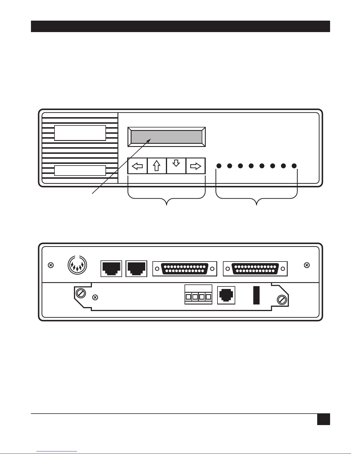
Figure 2-2). The front of the unit includes an LED
display, an LCD display, and a keypad.
The LED display monitors power status, self-test
results, link conditions, and voice and data channel
activities.
The LCD display provides status, events, and
messages, and together with the keypad is used for
configuration, diagnostics, and administration
functions.
The physical ports for connecting the Multiserver
500 to the various interfaces are on the back of the
unit.
2. Introduction
Figure 2-1. Typical Multiserver 500 Application.
PBX
MAINFRAME
LOCAL
MULTISERVER 500
COMPOSITE
LINK
REMOTE
MULTISERVER 500
VOICE
Page 12
CHAPTER 2: Introduction
11
Figure 2-2. Multiserver 500, Front and Rear Views.
LCD DISPLAY
KEYPAD
FRONT VIEW
REAR VIEW
LED INDICATORS
PO IS TD RD LS RS VA TM
MULTISERVER 500
DC POWER CMD
PORT-IN
EXE
CMD
PORT-OUT COMPOSITE DATA CHANNEL
FXS
SG R T
FXS
Page 13
MULTISERVER 500
12
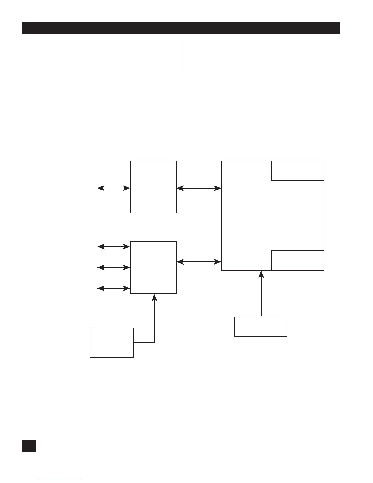
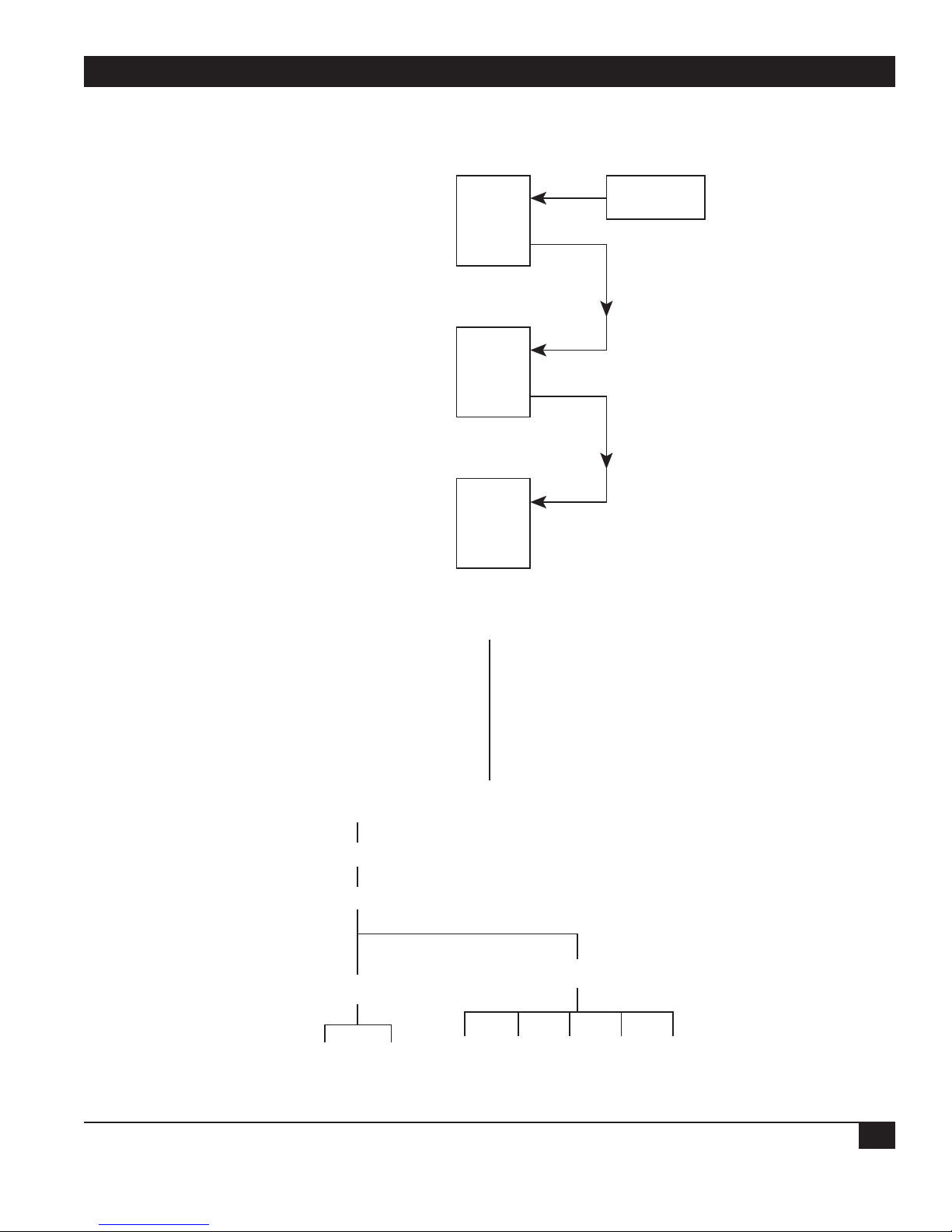
2.3 Block Diagram
Figure 2-3 is a diagram of the basic building blocks
that make up the Multiserver 500: the digital
processing module, the voice/fax interface module,
and the serial interface module. Attached to the
basic building blocks are the LCD display and
power-supply unit.
Figure 2-3. Multiserver 500 Block Diagram.
-
VOICE/FAX
INTERFACE MODULE DIGITAL PROCESSING MODULE
VOICE/FAX
SERIAL INTERFACE
MODULE
LED
DATA
COMPOSITE
COMMAND PORT
AC
POWER
POWER
SUPPLY
UNIT
KEYPAD
RIBBON
CABLE
LCD
Page 14

CHAPTER 2: Introduction
13
2.3.1 VOICE/FAX INTERFACE MODULE
The main function of the voice/fax interface
module is to convert the analog signals from the fax
machine or telephone equipment into digital form,
so they can be used by the digital processing
module. In addition, the voice/fax interface
module supplies impedance matching and signaling
conversion between the analog interface and the
Multiserver 500.
2.3.2 D
IGITAL PROCESSING MODULE
The digital processing module is the main
processing unit of the Multiserver 500. Its functions
include voice compression and multiplexing. In
addition, the LCD display and the keypad form part
of the digital processing module.
2.3.3 S
ERIAL INTERFACE MODULE
The serial interface module provides physical
connections for the data, composite, and Command
Port interfaces. It also contains the clockgenerating circuits derived either from internal or
external sources.
2.3.4 LCD
With the keypad, the LCD lets you configure and
monitor the Multiserver 500. It physically connects
to the digital processing module by a ribbon cable.
2.3.5 P
OWER SUPPLY
Power is supplied from a detachable power supply
through a connector at the back of the
Multiserver 500.
2.4 Interfaces
There are four interfaces that connect to the
Multiserver 500: data channel, voice/fax channel,
Command Port, and composite ichannel nterface.
2.4.1 D
ATA CHANNEL
The data channel interface is an RS-232 interface
terminated in a DB25 connector wired as DCE.
Support for V.35, RS-449/RS-530, and X.21 physical
levels is available on an optional basis, implemented
by daughterboards that plug into the serial
interface module.
The mux can accept both synchronous data
ranging from 1200 bps to 72,000 bps, and
asynchronous data ranging from 1200 bps to 57,600
bps.
2.4.2 VOICE/FAX CHANNEL
Depending on the type of telephone equipment (or
other analog equipment) interfacing with the
voice/fax channel, the voice/fax channel conforms
with one of three common types of signaling
conventions:
•FXS (Foreign Exchange Station)—Loop Start
•FXO (Foreign Exchange Office)—Loop Start
•E&M (E-lead and M-lead)—Tie Line Trunk
You can easily match the Multiserver 500 with the
correct telephone interface with a set of three
optional analog interface modules: FXS, FXO, and
E&M.
For more detailed information on the analog
interface modules, refer to Appendixes A, B, and C.
2.4.3 C
OMPOSITE CHANNEL
The composite is a synchronous channel ranging
from 7200 bps to 72,000 bps. Physically, the
composite channel is an RS-232 port terminated in
a DB25 connector wired as DCE. Support for V.35
RS-449/RS-530, and X.21 physical levels is also
available, implemented by daughterboards that
plug into the serial interface module.
2.4.4 C
OMMAND P
ORT
The Command Port is one way to access the
command facility of the Multiserver 500. Use the
command facility to issue commands and to
monitor status.
Physically, the Command Port is a set of two RJ-45
connectors at the back panel. It’s used to connect
an external asynchronous terminal to the
Multiserver 500.
In a single Multiserver 500 application, the CMD
PORT-IN connector is used for connection to the
terminal.
When several muxes are controlled by a single
terminal, the CMD PORT-IN connector connects to
the previous Multiserver 500 (or terminal, if it is the
first unit in line) and the CMD PORT-OUT
connector connects to the next Multiserver 500 in
Page 15

MULTISERVER 500
14
line.
2.5 Options
As described earlier, the composite port and data
channel interface connectors are wired, as
standard, for interfacing with RS-232 type devices.
You can change the interface with a conversion kit.
See the next section for the part numbers.
For additional information, refer to Appendixes D
and F.
2.6 Models Covered in This Manual
The basic Multiserver 500 is part number MX400A232/232. You might also have ordered it in any of
the optional configurations:
MX400A-35/35: V.35 composite interface, V.35 data
interface
• Base unit (MX400A-232/232)
• Two MX410C-35 Interface Cards
MX400A-422/422: RS-422 (X.21) composite interface,
RS-422 (X.21) data interface
• Base unit (MX400A-232/232)
• Two MX410C-422 Interface Cards
MX400A-422/35: RS-422 (X.21) composite interface,
V.35 data interface
• Base unit (MX400A-232/232)
• MX410C-422 Interface Card
• MX410C-35 Interface Card
MX400A-35/232: V.35 composite interface, RS-232 data
interface
• Base unit (MX400A-232/232)
• MX410C-35 Interface Card
MX400A-422/232: RS-422 composite interface, RS-232
data interface
• Base unit (MX400A-232/232)
• MX410C-422 Interface Card
In addition to the Multiserver 500 (MX400), this
manual covers the following voice/fax interface
card models:
• MX401C: Standard E&M Interface Module
• MX402C: Enhanced E&M Interface Module
• MX403C: Standard FXO Interface Card
• MX404C: Enhanced FXO Interface Module
• MX406C: Standard FXS Interface Card
• MX407C: Enhanced FXS Interface Module
Page 16

CHAPTER 3: Installation
15
Use the following procedures as a setup guide.
3.1 Unpacking the Multiserver 500
Unpack and inspect the equipment. Report any
physical damage to the shipping carrier. Save the
packing material. You may need it if you need to
return the unit for repair.
Check the contents of the equipment against the
packing slip. Verify that you have received the
following:
• The Multiserver 500
• If applicable, one modular cable for connecting
your FXS or FXO interface module to
telephone equipment
• One RJ-45-to-DB25 adapter
• One 8-conductor modular cable for use with the
adapter
• One power supply
Appendix F contains wiring diagrams for the above
cables. You may use them to construct your own
interface cables. Refer to Appendixes A, B, and C
for telephone interface cabling details.
3. Installation
Page 17

MULTISERVER 500
16
3.2 Installing the Multiserver
3.2.1 SELECTING AN INSTALLATION SITE
You can place the unit on a tabletop or shelf large
enough to accommodate it. Allow enough space to
get to the cables easily and remove the cover, and
make sure there is unobstructed air flow from the
sides of the unit.
3.2.2 C
ABLE AND POWER CONNECTIONS
Figure 3-1 shows the rear panel of the
Multiserver 500.
1. Composite Interface
Use a crossover cable appropriate for your
installation. (See Section F.1 in Appendix F.)
Connect one end to the COMPOSITE connector
and the other end to the DCE device.
2. Data Channel Interface
Use a straight cable appropriate for your
installation. (See Section F.2.) Connect one end to
the DATA CHANNEL connector and the other end
to the DTE device.
3. Telephone Interface
Requirements vary with the type of telephone
equipment you’re connecting to—and with the type
of voice/fax interface module installed in the
Multiserver 500. Refer to Appendixes A through C
for details.
4. Power Connection
Connect the power supply output directly into the
DC POWER connector of the Multiserver 500.
Connect the other end to an AC wall outlet.
Figure 3-1 Cable and Power Connectors.
ASYNCHRONOUS
TERMINAL
CONNECT TO
DCE DEVICE
CONNECT TO
DTE DEVICE
DC POWER CMD
PORT-IN
CMD
PORT-OUT COMPOSITE DATA CHANNEL
SG R T
FXS
FXS
Page 18

CHAPTER 3: Installation
17
WARNING!
Do not use any power supply other
than the one provided with your Multiserver 500, as illustrated in Figure 3-1.
Any other power supply could damage
the Multiserver 500.
5. Connecting a Terminal to the Command Port
See Chapter 6 for information on setting up and
using your terminal.
3.3 Setting the Composite Transmit Clock
If your composite interface is connected to a DCE
device as in Figure 3-2, verify that the composite
clock is set to external. You can do that from the
LCD/keypad:
Main Menu
Configure Parameter
Composite Link
External Clock
NOTE: As shown in Figure 3-2, the Multiserver 500
provides transmit and receive clocks to the
synchronous data interface.
CAUTION!
Once a pair of Multiserver 500s,
configured for external clocking, have
established communications, the
clocking rate provided from the link
DCE device cannot be changed. If the
DCE rate is changed you must either
cycle the power off and on on the
Multiserver 500 or disconnect the link
cable and then reconnect.
You can use two Multiserver 500s as a diagnostics
tool. Simply connect two Multiserver 500s back to
back and bench-test them. To do this, set both
muxes to internal clock and select a composite
clock rate.
Once you’ve selected a composite clock rate, you
must set both the local and remote muxes to the
same rate. The procedure is as follows (see
Figure 3-3 ):
2. Set the clock rate (9600) of the local unit to
external:
>COM C=EX R=9600 <cr>
Figure 3-2. Clocking with Multiserver 500 Connected to a DCE Device
DATA SOURCE MULTISERVER 500 DCE DEVICE
RxC
RxD
RxC
RxD
Set for
External
TxD
TxC
Clock
TxD
TxC
Page 19

Figure 3-3. Installing or Removing the Voice/Fax Interface Module.
MULTISERVER 500
18
3. Save the clock rate:
>SA
4. At the remote unit, repeat steps 2 and 3.
NOTE: Both the local and the remote Multiserver
500s must be set to the same composite
clock rate. Otherwise, the system will lock
up.
3.4 Installing the Voice/Fax Interface Module
Normally, the Multiserver 500 is shipped with the
voice/fax interface module already installed. If it
was shipped separately, or if you need to change the
existing module, see Figure 3-3 and proceed as
follows:
Tool Required: Medium-sized flat-head screwdriver.
To install:
1. Facing the rear of the Multiserver 500, place the
voice/fax interface module in the card guides,
then slide it toward the rear until it is firmly
seated in its mating connector in the digital
module.
DC POWER CMD
PORT-IN
CMD
PORT-OUT COMPOSITE DATA CHANNEL
FXS
SG R T
VOICE/FAX
INTERFACE MODULE
SCREW (2)
FXS
CAPTIVE
Page 20

CHAPTER 3: Installation
19
2. Secure the module with the two spring-loaded
captive screws. For further information,
including cable installation, refer to Appendix
A, B, or C.
To remove:
1. Using a medium-sized flat-head screwdriver,
unscrew the two spring-loaded captive screws.
2. Grasp the interface module firmly and slide it
slowly toward you until it’s free of its mating
connector, then slide it out of the
Multiserver 500.
3.5 Setting the Time and Date
To set the time of day and date from the Command
Port terminal, enter:
>U T=hh:mm:ss (set)
>U D=dd/mm/yy (set)
Note that time and date are not stored in EEPROM
(non-volatile memory), and must be set again each
time the Multiserver is powered up.
See Chapter 6 for additional Command Port
details.
To set the time of day and date from the
LCD/keypad, follow the diagram in Figure 3-4.
Page 21
MULTISERVER 500
20
Refer to Chapter 4 for additional LCD/keypad details.
Multiserver 500
Time 00:00:00
MAIN MENU
CONFIGURE PARAM
VOICE CHANNEL
SET TIME AND DATE
SET TIME
SET DATE
DATE: 01/01/00
SET
YEAR
DIGITS
LAST
SET
MONTH
DIGITS
NEXT
SET
DAY
DIGITS
FIRST
TIME: 00:00:00
Set hours digits first. Use up arrow to go
forward, use the down arrow to go
backward. When you’re finished, press
right arrow to advance to minutes.
Set minutes digits next. Use up/down
arrows. Press right arrow to advance to
seconds.
Set seconds digits last. Use right arrow to
return to main menu.
press down arrow
press down arrow
press down arrow
press left arrow twice
press down arrow
press down arrow
Figure. 3-4. Setting the Time and Date.
Page 22

CHAPTER 4: Using the LCD and Keypad
21
One of the ways to configure and monitor the
Multiserver 500 is to use the LCD/keypad. For the
Command Port method, see Chapter 5.
* NLP = Non-linear processing, which suppresses residual echo. In E&M 4-wire applications, voice quality
may be improved by disabling NLP.
Parameters shown in bold are default values.
4. Using the LCD and Keypad
Main Menu
Status Diagnostics Reset Configure
Voice
Channel
Interface
Analog
Busy
State
Composite
Link
Data
Channel
Background Fax
Param
Command
Port
Factory
Default
Load
From
Mode
Save
EEPROM
Set
Password
Set Time
and Date
NLP Mode*
Silence
Disable EnableOn SystemOff
Regenerated Disable Enable
Page 23

MULTISERVER 500
22
* If you operate your equipment in the U.S.A. or Canada, input gain and output attenuation levels must be
set to 0 dB. In other countries, follow the standards of the country where the equipment is being used. If
there are no specific standards, set the input and output levels of your equipment to match the interfacing
telephone equipment.
Parameters shown in bold are default values.
Configure Param (cont.)
Analog Interface
Ringing
Frequency
Signalling
Format
DC Pulsed
DC
AC-15
Input Gain* Output
3 2 1 0 -1 -2 -3
4
5
6
7
8
9 10 19 20
Operation Extra Gain
2-Wire 4-Wire None 7
-4
-5
-6
22
21
25_Hz 50_Hz
Attenuation*
Interrupted
3 2 1 0 28 27 26
4
5
6
7
8
Ring Type Impedance
2-4
Interrupted
Repeated
1-2
600 Ohms Complex
25
24
23
22
21
9 10 19 20
Page 24

CHAPTER 4: Using the LCD and Keypad
23
NOTE: When you change these Command Port parameters, they become effective after you select a Save
and then a Reset.
* Does not include parity bit.
Parameters shown in bold are default values.
Configure Param (cont.)
Command Port
Parity Stop
Bits
1 21.5
Auto
1200
Data*
Bits
2400
4800
9600
Data
Rate
19200
Flow
Control
None Xon/Xoff 0........8
Enable Disable7 8
Local
Echo
Device
Number
None Even Odd Mark Space
Page 25

MULTISERVER 500
24
* Does not include parity bit.
Parameters shown in bold are default values.
(see next page for
parameters)
Configure Param (cont.)
Data Channel
Echo Flow
None Even Odd Mark Space
Enable Disable
1200
2400
1 1.5
3600
2 7 8
4800
7200
Asynchronous Synchronous
Data RateData Bit*Stop BitsParity
Control
Xon/Xoff
None
9600
14400
19200
28800
38400
EIA
Signal
CTS/
RTS
57600
RI DSR Control DCD Control CTS Control CTS
On
Off
Link
Off
On
Status
Remote
DTR
On
Off
Remote
RTS
On
RTS
Delay
Off
Local
RTS
125 ms 150 ms100 ms75 ms50 ms25 msNone
Page 26

CHAPTER 4: Using the LCD and Keypad
25
NOTE: The Multiserver 500 will not operate with clock rates, internal or external, other than those specified
above.
* Refer to Section 6.4.1 for a definition of Dynamic Bandwidth Allocation.
Parameters shown in bold are default values.
Configure Param (cont.)
Data Channel (cont.)
Synchronous
Rate Max
1200
(rate)
2400
3600
4800
7200
Transmit
Rate
12000
14400
9600
Internal Clock External Clock
28800
19200
Clock
Internal External
46400
33600
38400
Composite Link
48000
Off
56000
51200
Dynamic*
Bandwidth
Silence
57600
64000
Hook
72000
(maxrate)
9600
7200
14400
Clock Rate
19200
38400
56000
72000
64000
Page 27

MULTISERVER 500
26
* Shows status of all configuration parameters, as selected.
Main Menu (cont.)
Status
self test passed
self test active
checksum failed
ram failed
eeprom passed
eeprom failed
Analog
Interface
H/W Rev.
Dash No.
Configuration
Type
S/W Rev.
Dash No.
Remote Comp.
Local Comp.
Remote Data
Local Data
Comp. Loop
Data Loop
DSP
Dash No.
H/W
Rev.
Serial
Board
H/W Rev.
SystemDiagnosticsCurrent*
Type
Voice
Channel
I/F
Link
Status
CompositeSelf Test Analog
Clock
Rate
Data
Channel
Out
Level
Algorithm
Verification
I/F Type
Rate
PROM
Algorithm
Ver.
PROM
I.D.
Local
On/Off
Hook
Remote
On/Off
Hook
In
Level
Receive
Clock
Transmit
Clock
EIA
Signal
B0=
CTS
RTS
DCD
DTR
RI
DSR
UNA
Flow
Control
=
=
=
=
=
=
=
Page 28

CHAPTER 4: Using the LCD and Keypad
27
Main Menu (cont.)
Diagnostics
Composite
Remote
Composite
Local
Data
Remote
Data
Self
Test
TerminateLocal
EEPROM
Page 29

MULTISERVER 500
28
In addition to performing all of the functions from
the LCD/keypad, you can also do the same thing
with an asynchronous terminal connected to the
Command Port (with the exception of setting the
device number). This section describes how to
configure and strap the Command Port and how to
connect the asynchronous terminal to the
Command Port.
Once you’ve configured the Command Port and
connected the asynchronous terminal, you can use
the Command Port to configure and monitor the
Multiserver 500. See Section 6.3 for default details.
5.1 Factory Defaults
The factory defaults of the Command Port are as
follows:
Data Rate: Automatic Baud Rate
(ABR)
Number of Data Bits: 8
Parity: None
Number of Stop Bits: 1
Flow Control: None
Device Number: 0
Local Echo: Enabled
If your terminal meets all of the above parameters
(with the exception of device number), including
any of the compatible ABR rates, your Command
Port is ready for operation. ABR is compatible with
1200, 2400, 4800, 9600, and 19,200 bps.
Otherwise, the Command-Port parameters must
be reconfigured from the LCD/keypad, as shown in
Figure 5-1.
5. Using the Command Port
Page 30

CHAPTER 5: Using the Command Port
29
Main Menu
Figure 5-1. Reconfiguring the Command-Port Parameters.
Configure Parameter
Analog
I/F
Voice
Channel
Parity Stop Bit
121.5
Composite
Link
Data
Bits
Data
Channel
Command
Port
Data
Rate
Save
To
Load
From
Set Time
& Date
Flow
Control
None Xon/Xoff 0........8
Enable Disable8 7
Local
Echo
Set
Password
Device
Number
None Even Odd Mark Space
Auto
1200 2400 4800 9600 19200
Page 31

MULTISERVER 500
30
5.2 Connecting Asynchronous Terminals
The Command Port includes an interface
connector, so you can connect an asynchronous
terminal. The interface connector also lets you
control multiple Multiserver 500s from a single
terminal in a daisychain fashion.
5.2.1 C
ONNECTING A
SINGLE MULTISERVER 500
As shown in Figure 5-2, there are two RJ-45-type
Command Port connectors located on the rear
panel of the Multiserver 500: CMD IN and CMD
OUT. Cable requirements and pinouts are detailed
in Section 5.4. If your installation includes a single
Multiserver 500, connect the asynchronous terminal
to CMD IN. You will need an RJ-45 to DB25 adapter
to connect the cable to the asynchronous terminal.
NOTE: In a single-unit installation, the device
number must be left at its default value of 0,
and you must strap the Multiserver 500 for
the low-impedance position. Strapping
details are covered in Section 5.3.
5.2.2 C
ONNECTING MULTIPLE MULTISERVER 500S
Figure 5-2. Connecting the Asynchronous Terminal.
DC POWER CMD
PORT-IN
CMD
PORT-OUT COMPOSITE DATA CHANNEL
SG R T
FXS
FXS
Page 32
CHAPTER 5: Using the Command Port
31
You can connect up to eight Multiserver 500s in a
daisychain and control the chain from a single
asynchronous terminal. Figure 5-3 shows the
topology for a typical three-Multiserver 500 local
installation. Before connecting them, you must
configure each Multiserver 500 with a fixed data
rate and then with a device number from the LCD
and keypad. (See Figure 5-4.) The default values are
8 data bits, 1 stop bit, no parity, autobaud, no flow
control, and local echo enabled.
At least one unit must be set to 1; each of the
other units may be set randomly to any number in
the range of 2 through 8, as long as no two units
have the same number.
5.3 Impedance Strapping
Multiserver 500
Figure 5-3. Typical Three-Multiserver Daisychain Topology.
Figure 5-4. Setting the Data Rate and Device Number.
Unit 1
Strap
for High Impedance
Multiserver 500
Strap
for High Impedance
Multiserver 500
Strap
for Low Impedance
Main Menu
Cmd
In
Cmd
Out
Unit 2
Cmd
In
Cmd
Out
Unit 3
Cmd
In
Cmd
Out
Async
Terminal
Configure Parameter
Command Port
Device Number
0.............8
Auto
Data Rate
1200 4800 9600 19200
Page 33

MULTISERVER 500
32
You can strap the Command Port receiver for either
high-impedance (30K Ω) or low-impedance (5K Ω)
termination, implemented by a three-position
header E5 and a 2-position jumper. Figure 5-5 shows
the location E5 on the serial interface module. See
Section D.1 for accessing the serial interface
module.
• To strap for low-impedance termination,
position the jumper over pins 2 and 3.
• To strap for high-impedance termination,
position the jumper over pins 1 and 2.
Impedance requirements are as listed in Table 5.1.
Figure 5-5. Location of Command-Port Impedance Header E5 on the Serial Interface Module.
Table 5-1. Impedance-Strapping Requirements
Number of Multiserver 500s Strapping Requirements
---------------------------------------------------------------------------------------------------------------------------------------------------------------1 Strap E5 for low impedance.
----------------------------------------------------------------------------------------------------------------------------------------------------------------
2 through 4 Strap E5 on end unit for low impedance. Strap E5 on all other
units for high impedance.
----------------------------------------------------------------------------------------------------------------------------------------------------------------
5 through 8 Strap E5 on all units for high impedance.
E4
J9 J8
E5
Low
3
2
1
J11 J10
E11
E5
Impedance
High
3
2
E5
1
Impedance
Page 34
CHAPTER 5: Using the Command Port
33
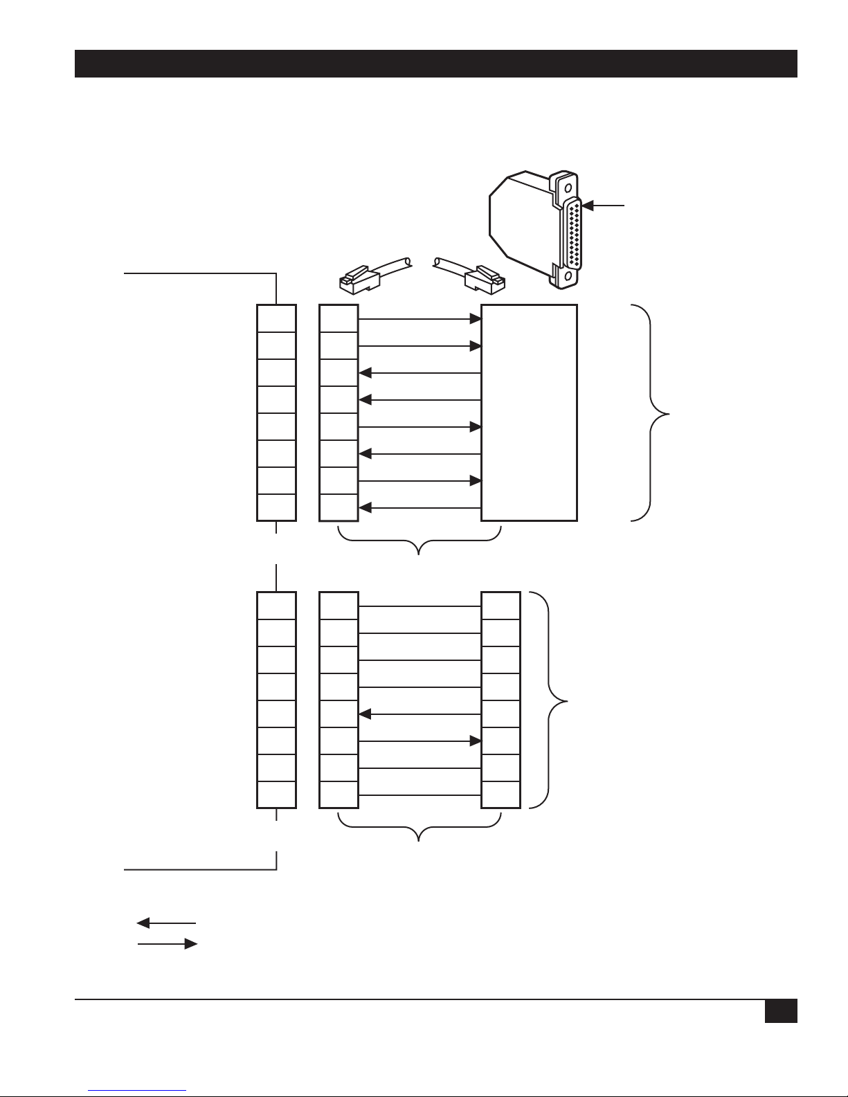
5.4 CMD IN and CMD OUT Connectors
Figure 5-6 shows the pin assignments for the CMD
IN and CMD OUT connectors.
Figure 5-6. CMD IN and CMD OUT Connector Pin Assignments (RS-422 Interface).
Multiserver 500
PIN 1
n/c
force to mark
n/c
Ground
Command Data Out
Command Data In
force to mark
n/c
n/c
n/c
n/c
Ground
Daisy-chain Data In
1
2
3
4
5
6
7
8
CMD Port-In
Connector
1
2
3
4
5
1
2
3
4
1
2
3
4
22
8
20
7
RI
RLSD
DTR
Ground
To
5
6
7
8
Modular
Cable
1
2
3
4
5
5
6
7
8
RJ-45 to
DB25 Adapter
1
2
3
4
5
RD
3
TD
2
CTS
5
RTS
4
Terminal
To CMD Port-in of next
Multiserver 500 in daisy-chain
Daisy-chain Data Out
n/c
n/c
Legend:
= Input to Multiserver 500
= Output from Multiserver 500
6
7
8
CMD Port-Out
Connector
6
7
8
Modular
Cable
6
7
8
Page 35

MULTISERVER 500
34
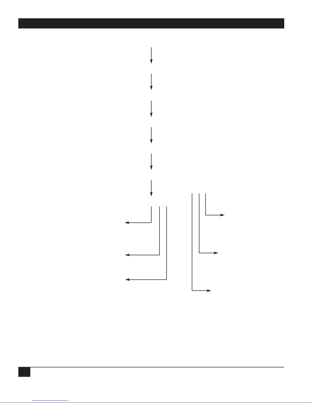
5.5 Accessing the Command Port
To access the Command Port from the asynchronous terminal, follow the flowchart in Figure 5-7.
Figure 5-7. Flowchart for Accessing the Command Port.
Power Up
N
N
Daisy
Chain
N
Command
Port
ABR
Y
Enter
<cr><cr>
in quick succession
Password
Configured
Y
Enter
<Ctrl> C
Enter
Device
Number
Multiserver 500 Display
Copyright (c) 1993
All rights reserved
Y
Enter
Password
1 2 3
Page 36

CHAPTER 5: Using the Command Port
35
Figure 5-7. Flowchart for Accessing the Command Port (continued).
* If daisychaining or reconfiguring Command Port, enter <Ctrl> C to end session. Otherwise, enter <exit>.
1
Start
Session
To Change to Remote
Command Port,
enter <Remote> command
To Return to Local
Command Port,
enter <Exit> command
N
Session
Completed
2 3
Y
Either* Or*
Enter
<Ctrl> C
Enter
<Exit>
Page 37

MULTISERVER 500
36
When you type a command, you need only type the
first few unique letters. In the lists of commands in
this manual, the capitalized part of a command is
the minimum you must type for the Multiserver to
recognize it.
Configuring the Prompt
When you first turn on the Multiserver 500, the
following prompt will appear on the terminal
screen: >.
You can change the prompt to whatever you like. To
change it to “Multiserver 500>,” enter:
UNit PRompt = Multiserver 500 <CR>
The prompt will change to:
Multiserver 500>
The prompt thus configured becomes automatically
active for the duration of the session. You can make
this permanent by issuing a SAve command.
List of Commands
To get a list of commands, enter a question mark
(?) followed by a <cr>.
Multiserver 500>?<cr>
The following list will appear:
Command Function
AInterface* Configures the analog interface
portion of the voice/fax parameters.
ASyncport* Configures the async data port
parameters.
CMDport* Configures the Command Port’s
parameters.
COMPositelink* Configures the composite link
parameters.
<Ctrl>C Terminates all command sessions.
DAtaport* Configures the data port type and
controls.
Command Function
DIagnostics* Performs diagnostic tests.
Exit Terminates the current command
session.
LOAd Sets parameters to factory-default
values or last saved configuration
values.
Remote Accesses remote Command Port.
SAve Command to save modified
configuration in EEPROM (nonvolatile memory), replacing the
default parameters. Command will
take effect after unit is reset.
SHow* Displays selected information such
as status and statistics.
SYncport* Configures parameters for the sync
data port.
Unit* Changes system-level parameters.
Voiceport* Configures the digital portion of the
voice/fax parameters.
How to Enter Commands and Set Parameters
There are no menus when you use the command
port. Instead, you enter a command or a string of
commands that are specific to the parameter (or
parameters) you intend to set or change, bypassing
all intermediate steps.
• Commands are not case-sensitive.
• The upper-case letters shown in the list of
commands are for your information only. They
indicate the minimum number of characters
required to execute that command.
• Commands that require parameters are
followed by an asterisk (*). For more
information about a specific command’s
parameters, type the command name, followed
by a space, followed by a ?.
Example: >DA ? (Data port).
• A command without an asterisk will not display
* For these commands, you must enter parameters. To get a display of parameters available under each
command, type in the command name, followed by a space, followed by a question mark (?), followed by
<cr>. For example, to get the sync port parameters, type SY ?<cr>.
Page 38

CHAPTER 5: Using the Command Port
37
more information, but will be executed when
entered.
• Parameters of the same command may be
chained together as a single entry, with each
parameter separated by a space. The chain
cannot exceed 80 characters, including spaces.
Example: to configure CTS and DSR in the data
port async channel, you could enter the
following string: data=as cts=on dsr=on.
(NOTE: The equal sign = may be replaced by a
space.)
List of Parameters
Following is a list of parameters associated with each
of the commands marked with an asterisk in the list
of commands.
AInterface
INput_gain (dB) -6 through 22
Output_Attn (dB) 0 through 28
OPeration (E&M) 2_wire, 4_wire
Signalling_format (E&M) DC, AC-15, Pulsed_DC
IMpedance 600 ohms, Complex
RINGTYPE (FXS) 2-4_interrupted,
1-2_interrupted
RINGFreq (FXS) 25_Hz, 50_Hz
Extra_gain (E&M 4-wire) None, 7 dB
Example: >AI IN=-6 OUT=4 RING T=2-4
IMp=600<cr> will set the FXS input gain to -6 dB,
the output attenuation to 4, the ringing type to 2-4,
and the line impedance to 600 Ω
NOTE: If your equipment is operated in the U.S.A.
or Canada, input and output levels must be
set to 0 dB. In other countries, follow the
standards of the country wherein the
equipment is used. If there are no specific
standards, set the input and output levels of
your equipment to match the interfacing
telephone equipment.
Be sure to separate each command in the string by
a space.
The parameters above become effective
immediately when entered, but are not stored in
EEPROM (nonvolatile memory) until saved. To save
the newly set parameters in EEPROM, type >SA
<cr>.
ASyncport
Rate (bps) 1200, 2400, 3600, 4800,
7200, 9600, 14400,
19200, 28800, 38400,
57600
Data_bit 8, 7
Stop 1, 1.5, 2
Parity None, Even, Odd,
Mark, Space
Flow_control None, Xon/Xoff,
CTS/RTS
Echo Disable/Enable
Example: >AS RA=7200 D=7 P=O <cr> will
set the async channel rate to 7200 bps, the number
of data bits 7, and parity to odd.
Be sure to separate each command in the string
with a space.
To save the newly set parameters in EEPROM,
type >SA <cr>.
CMD port
Rate (bps) AUTO*, 1200, 2400,
4800, 9600, 19200
Data_bit 8, 7 (Does not include
parity bit)
Stop 1, 1.5, 2
Parity None, Even, Odd,
Mark, Space
Flow_control None, Xon/Xoff
Echo Enable, Disable
* The Automatic baud rate option is available only to terminals that use an 8-bit, no parity, 1 stop bit format.
Page 39

MULTISERVER 500
38
Device Number: 0 through 8
Example: >CMD RA=9600 will set the Command
Port rate to 9600.
Be sure to separate each command in the string
by a space. To save the newly set parameters in
EEPROM, type >SA <cr>.
COMpositelink
Clock External, Internal
Rate (bps) 7200, 9600, 14400,
19200, 38400, 56000,
64000, 72000
Example: >COM CL=EX RA=56000 <cr>, will set
the composite port clock to external, and the rate
to 56,000 bps. Rate selection applies to internal
clock only.
Be sure to separate each command in the string
by a space. To save the newly set parameters in
EEPROM, type >SA <cr>
DAtaport
Use this command to select the data port type and
parameters that are common to both the
synchronous and asynchronous data channels.
Parameters that are unique to the synchronous and
asynchronous channels are set by separate
commands for each type.
Type Asynchronous,
Synchronous
CTS ON, OFF, Local
(Follows local RTS)
CTSDelay None, 25, 75, 100, 125,
150 in msec
DCD ON, OFF, Remote
(follows remote RTS)
DSR ON, OFF, Remote
(follows remote DTR)
RI ON, OFF, Link (follows
link status)
Example: >DA TY=SY RI=OFF will set the data
port type to synchronous, and the ring indicator to
off.
Be sure to separate each command in the string
by a space. To save the newly set parameters in
EEPROM, type >SA <cr>.
DIAgnostics
SElftest Initiates a self-test
EEprom Initiates a nonvolatile
RAM check
LOCComp Initiates a local
composite loopback
REMComp Initiates a remote
composite loopback
LOCDat Initiates a local data
channel loopback
REMDat Initiates a remote data
channel loopback
TErminate Terminates test in
progress, such as selftest or loopback
Example: To initiate a remote-data-channel
loopback test, type: >DI REMD <cr>.
SHow
DATE Displays today’s date
Example: >SH DATE 03/11/94
Status Displays Multiserver
500’s current general
status, including selftest, loopback, and
hardware type and
revision.
Example: >SH S
System Status: 20 MHz DSP, 64K RAM,
no download capability
Main module 001 Voice & Data
Revision Level: B
Voice/Fax Interface Module: 002
Revision Level: 03
Interface Type: Enhanced FXS, Loop
start.
Page 40

CHAPTER 5: Using the Command Port
39
Serial Module 001 Voice & Data
Revision Level: B
Serial Module Type: Standard
Self-Test passed, EEPROM passed, No
active loopback
COMposite Displays the current
status of the composite
link, including rate,
clock, and link.
Example: >SH COMP
COMPOSITE LINK STATUS
Link Up, External Clock Rate = 19200
VOice Displays the current
status of the voice/fax
channel, including rate,
on-hook/off-hook,
input/output levels,
etc.
Example: >SH VO
Voice Channel Status
Local = on-hook, Remote = on-hook,
Level In = 0, Level Out = 0
Algorithm rate = 16000,
Algorithm ver. = 0,
Analog interface Status:
Interface Type = Enhanced FXS,
PROM version = 2A, PROM I.D. = 2196
DATA Displays the current
EIA status of the data
channel, including
type, rate, flow control
and EIA signal status.
Example: >SH DATA
Data Channel Status:
EIA SIGNAL
Input:
UNA = OFF, B0 = OFF, RTS = OFF,
DTR = OFF
Output:
DCD = OFF, RI = OFF, CTS =ON
DSR = OFF, for Synchronous Data:
Synchronous Tx Data Rate = 56000,
Rx Data Rate = 56000 for Asynchronous
Data:
Asynchronous data rate = 9600, flow
control = OFF
Time Displays current time
Example: >SH T
02:59:37
VErsion Displays the current
software revision.
Example: >SH VE
Software Revision: 907-2200-0
CONfiguration Displays the current
configuration of the
data channel,
Command Port,
composite link,
voice/fax channel, and
the analog interface
portion of the
voice/fax channel. See
the explanation below.
Example: >SH CON
Data Channel configuration
Type = Asynchronous, CTS = ON,
CTSDelay = None, DCD = Remote rts,
DSR = Remote dtr, RI = Link status,
Rate = 9600, Data_bit = 8, Stop =
1, Parity = None, Flow_control =
None, Echo = Disable
Command port configuration
device number = 1, Rate = 9600,
Data_bit = 8, Stop = 1, Parity =
None, Flow_control = None, Echo =
Page 41

MULTISERVER 500
40
Enable
Voice Channel configuration
BUSYstate = SYStem,
BACKground = Silence, FAX = Disable,
NLP = Enable
Composite Link configuration
Clock = External, Rate = 9600
Analog Interface configuration
INput_gain(dB) = 0, Output_attn
(dB) = 0, RINGType =
2-4_interrupted,
RINGFreq = 25_Hz,
IMpedance = 600 Ohms
Unlike SHow CONfiguration, SHow DATA always
displays the parameters currently stored in
EEPROM (nonvolatile memory).
To activate the newly set configuration, type >U R
<cr> (unit reset).
This message might appear:
Data and composite parameters
effective after unit reset.
When that message appears, the data and
composite parameters displayed have been recently
modified but not made effective. After you use the
save command and reset the unit, the modified
parameters will be stored in EEPROM (nonvolatile
memory) and the message above will disappear.
Unlike data and composite parameters, voice and
analog parameters take effect immediately when
you enter them.
SYnc port
Rate* or Maxrate (bps): 1200, 2400, 3600, 4800,
7200, 9600, 12000,
14400, 19200, 28800,
33600, 38400, 46400,
48000, 51200, 56000,
57600, 64000, 72000
Tx clock Internal/External
DBA OFF, SILENCE, HOOK
Example: >SY RA=38400 MAX=56000
DBA=HOOK <cr> will set the sync channel
minimum rate to 38,400 bps, maximum rate to
56,000 bps, and DBA (dynamic bandwidth
allocation) will follow the on-hook/off-hook state of
the voice/fax channel.
Be sure to separate each command in the string
by a space.
To save the newly set parameters in EEPROM,
type >SA <cr>. To activate the newly set
parameters, type: >U R <cr> (unit reset).
Unit
Available parameters are:
Date, Reset, Time, PAssword, PRompt
When you enter the parameters listed above, they
take effect immediately. Date and time cannot be
saved and will be lost when power is disconnected.
You must save password and prompt in order for
them to remain in effect after a power off/on cycle.
VOice Port
BUsy State OFF, ON, SYstem
BAckground Silence, Regenerated
Fax Disable, Enable
NLP† Disable, Enable
Example: >BUsy SY will set the busy state to
system-controlled.
Be sure to separate each command in the string
by a space. The above parameters become effective
immediately when entered, but are not stored in
EEPROM (nonvolatile memory) until saved. To save
the newly set parameters in EEPROM, type >SA
<cr>.
*Guaranteed rate. †NLP = Non-Linear Processing.
Page 42

CHAPTER 6: Operation
41
This section describes how the Multiserver 500
works. Indicators are described first, followed by
procedures for transmitting data, making telephone
calls, and sending fax messages.
6.1 LED Indicators
LED indicators are on the front panel of the
Multiserver 500, as shown in Figure 6-1. Their
functions are summarized in Table 6-1.
6. Operation
Figure 6-1. The Front Panel of the Multiserver 500.
MULTISERVER 500
PO IS TD RD LS RS VA TM
EXE
KEYPAD LED INDICATORSLCD DISPLAY
Page 43

MULTISERVER 500
42
Table 6-1. LED Indicators
Indicator State Meaning
----------------------------------------------------------------------------------------------------------------------------------------------------------------
PO (Power On) On Unit is powered up and has passed the self-test.
Off Power is off.
Flashing Self-test failed.
----------------------------------------------------------------------------------------------------------------------------------------------------------------
IS (In Sync) On The local Multiserver 500 is in sync with the remote
Multiserver 500.
Off The local and remote Multiserver 500s are out of
sync.
----------------------------------------------------------------------------------------------------------------------------------------------------------------
TD (Transmit Data) Flickering Data channel is transmitting data.
Off Data channel is not transmitting.
----------------------------------------------------------------------------------------------------------------------------------------------------------------
RD (Receive Data) Flickering Data channel is receiving data.
Off Data channel is not receiving data.
----------------------------------------------------------------------------------------------------------------------------------------------------------------
LS (Local Speech) On Speech signal from local telephone interface present.
Off No local speech present.
----------------------------------------------------------------------------------------------------------------------------------------------------------------
RS (Remote Speech) On Speech signal from remote telephone interface
present.
Off No remote speech present.
----------------------------------------------------------------------------------------------------------------------------------------------------------------
VA (Voice Active) On Voice channel is active.
Off Voice channel is idle.
Flashing Voice channel is busy.
----------------------------------------------------------------------------------------------------------------------------------------------------------------
TM (Test Mode) On Multiserver 500 is in test mode.
Off Multiserver 500 is not in test mode.
Flashing Test failure.
Page 44

CHAPTER 6: Operation
43
6.2 The LCD and the Keypad
The two-line LCD (Liquid-Crystal Display) shows
configuration menus, diagnostic test menus and
results, time of day, and system status. A keypad lets
you cycle through the LCD menu and make
configuration selections. Chapter 5 explains how to
use the LCD and keypad.
6.3 Default Configuration Settings
When the Multiserver 500 is first turned on, the
interfaces are configured with the following default
values:
Analog Interface
Input Gain: 0 dB*
Output Attenuation: 0 dB*
Operation (E&M): 4-wire
Signaling Format (E&M) DC
Impedance: 600 Ohms
Ringing Type (FXS) 2-4 interrupted
Ringing Frequency (FXS): 25 Hz
Extra Gain (E&M 4-wire): None
CMDport
Rate AUTO
Data bit 8
Stop 1
Parity None
Flow control None
Echo Enable
COMpositelink
Clock External
Rate 9600
DAtaport
Type: Synchronous
CTS: ON
CTSDelay: None
DCD: ON
DSR: ON
RI: Link status
ASyncport
Rate: 1200 bps
Data bit: 8
Stop: 1
Parity: None
Flow control: None
Echo: Disable
SYncport
Rate: 1200 bps
Maxrate: 72,000 bps
Txclock Internal
DBA OFF
* If you operate your equipment in the U.S.A. or Canada, input gain and output attenuation levels must be set
to 0 dB. In other countries, follow the standards of the country where the equipment is used. If there are no
specific standards, set the input and output levels of your equipment to match the interfacing telephone
equipment.
Page 45

MULTISERVER 500
44
Voiceport
BUSYstate SYStem
BACKground Silence
FAX Enable
NLP Enable
You can change the default values either from the
LCD/keypad (refer to Chapter 5) or from the
Command Port (refer to Chapter 6).
6.4 Operating the Multiserver 500
NOTE: If link rate is less then the configured max
rate, the maxrate need not be reconfigured.
6.4.1 ESTABLISH A DATA CONNECTION
1. Connect a synchronous or asynchronous
terminal, as applicable, to the DATA CHANNEL
connector at the rear of the Multiserver 500.
Use the appropriate straight cable as described
in Section F.2 in Appendix F.
2. Make sure that the Multiserver 500 is configured
to meet the requirements of the data source. If
not, reconfigure from either the LCD/keypad
(refer to Chapter 5) or the Command Port
(refer to Chapter 6). You can check the current
configuration values with a SHow
CONfiguration command from the Command
Port terminal, or by entering the STATUS
CONFIGURATION menu from the
LCD/keypad.
3. Enter data from the keypad on the data
terminal.
Notes About the Data Channel
When the data channel is synchronous, you may
configure it for either fixed or dynamic bandwidth
allocation.
Fixed bandwidth allocation means that the channel
always operates at a fixed rate as specified by the
configured “rate” parameter.
In dynamic bandwidth allocation, two rate
parameters are specified: “rate” and “maximum
rate.” “Maximum rate” is the amount of link
bandwidth allocated to the synchronous data
channel when the voice channel is not in use.
When the voice channel is in use, the synchronous
data channel automatically drops down to the “rate”
value, a guaranteed value of bandwidth allocation.
Once the voice channel is no longer in use, datachannel bandwidth allocation returns to the
maximum value.
There are two ways to define when the voice
channel is in use: silence and hook.
When you select hook, the voice channel is
considered to be in use as soon as a voice (or fax)
connection is established, and will continue to be in
use until both sides hang up.
When you select silence, the voice channel is
considered to be in use only while voice or fax
traffic is in progress, and only in the direction of
the traffic. In that direction the bandwidth of the
synchronous data channel will drop from the
“maximum rate” to the guaranteed “rate” speed.
6.4.2 T
O MAKE A TELEPHONE CALL
Your Multiserver 500 voice/fax channel is dedicated
for operation with a compatible voice/fax channel
installed at the remote Multiserver 500. Making a
telephone call depends on the type of voice/fax
interface module installed at each end. It may be as
simple as lifting the telephone off-hook (FXS-toFXS) and waiting until the other party answers, or
lifting the telephone and dialing if either end is
fitted with an FXO or E&M voice/fax interface
module.
Figure 6-2 shows the steps involved in making a
telephone call when the Multiserver 500 at the local
end is fitted with an FXS voice/fax interface
module. Figure 6-3 shows the steps involved when
the Multiserver 500 at the local end is fitted with
either an FXO or E&M interface module.
Page 46
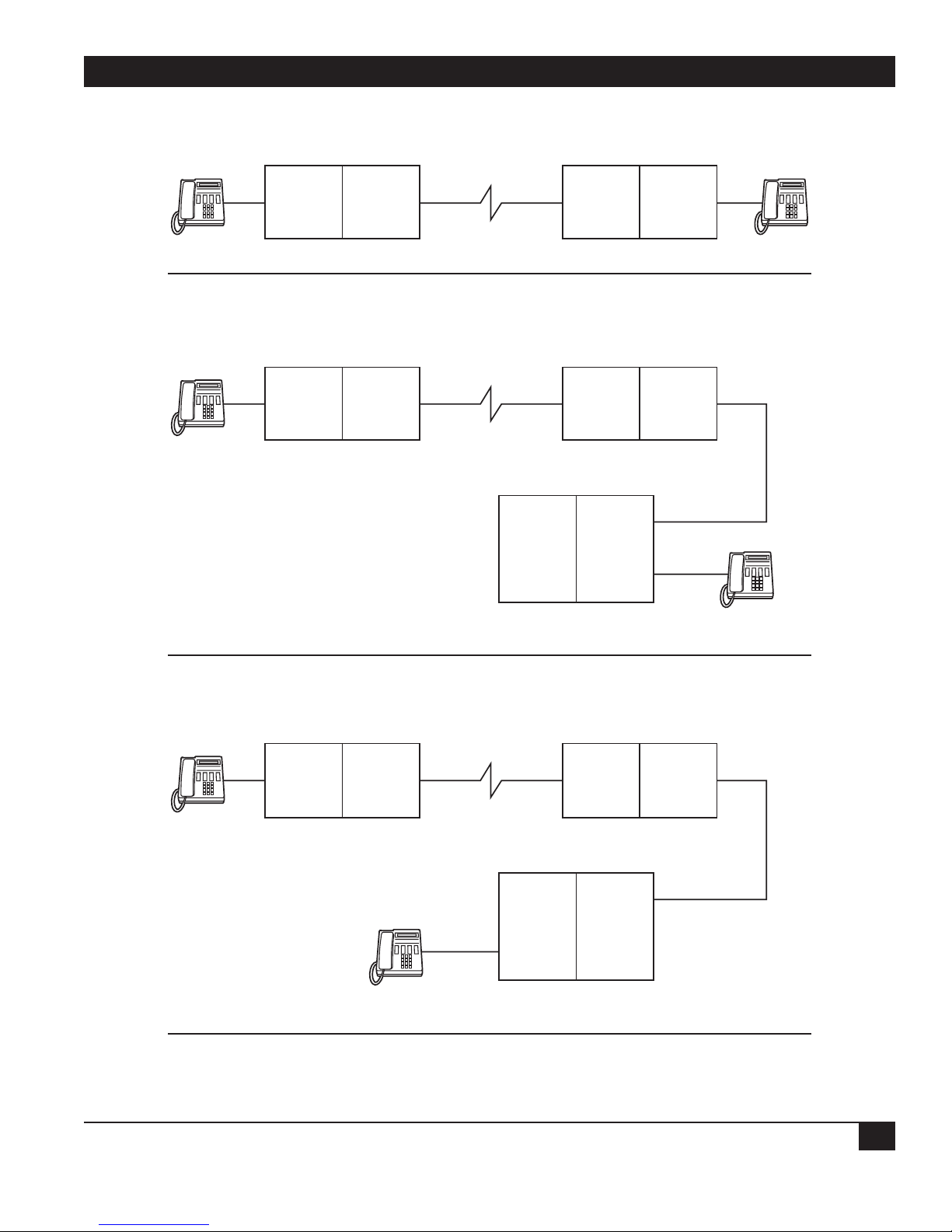
CHAPTER 6: Operation
45
Figure 6-2. Telephone Calls from Local FXS Interfaces.
Lift telephone and speak when other party answers.
Lift telephone. Wait for dial tone from PBX. Dial 456, speak when other party
answers.
Lift telephone. Wait for dial tone from PBX. Dial 456. Speak when other party
answers.
LOCAL
MULTISERVER 500
FXS
I/F
Module
Digital
Proc
Module
FXS-TO-FXO
LOCAL
MULTISERVER 500
FXS-TO-FXS
FXS
I/F
Module
Digital
Proc
Module
Trunk
Side
REMOTE
MULTISERVER 500
Digital
Proc
Module
REMOTE
MULTISERVER 500
Digital
Proc
Module
PBX
Station
Side
FXS
I/F
Module
FXO
I/F
Module
ST 123
ST 456
FXS-TO-E&M
LOCAL
MULTISERVER 500
FXS
I/F
Module
Digital
Proc
Module
ST 456
PBX
Station
Side
REMOTE
MULTISERVER 500
Digital
Proc
Module
Trunk
Side
E&M
I/F
Module
Page 47
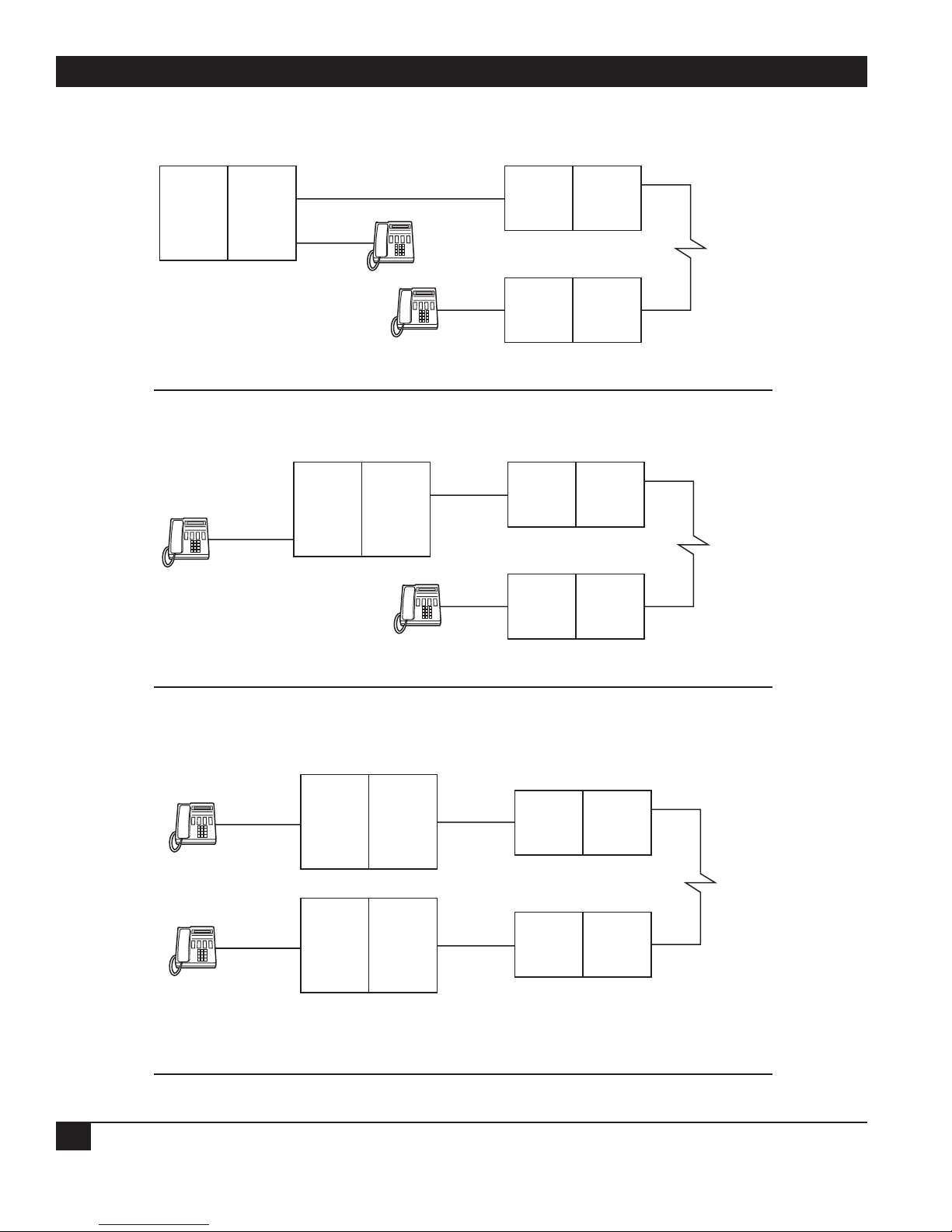
MULTISERVER 500
46
Figure 6-3. Telephone Calls from Local FXO or E&M Interfaces.
Lift telephone at local station 123. Wait for dial tone from PBX. Dial 456. Speak
when other party answers.
Lift telephone at local station 123. Wait for dial tone. Dial access code 8. Speak
when other party answers.
Lift telephone at local station 123. Wait for dial tone from local PBX. Dial access
code 8. Wait for dial tone from remote PBX. Dial station 456. Speak when the
other party answers.
Trunk
Side
FXO-TO-FXS
PBX
ST 456
Station
Side
ST 123
LOCAL
MULTISERVER 500
FXO
I/X
Module
MULTISERVER 500
FXS
I/X
Module
Digital
Proc.
Module
REMOTE
Digital
Proc.
Module
ST 123
Station
Side
E&M-TO-FXS
PBX
8
Trunk
Side
LOCAL
MULTISERVER 500
E&M
I/X
Module
MULTISERVER 500
Digital
Proc.
Module
REMOTE
FXS
I/X
Module
Digital
Proc.
Module
E&M-TO-E&M
LOCAL PBX
ST 123
ST 456
Station
Side
REMOTE PBX
Station
Side
Trunk
Side
Trunk
Side
8
8
LOCAL
MULTISERVER 500
E&M
I/X
Module
MULTISERVER 500
E&M
I/X
Module
Digital
Proc.
Module
REMOTE
Digital
Proc.
Module
Page 48

CHAPTER 6: Operation
47
Notes About Voice/Fax Channel Parameters
• Voice/fax channel parameters are configured
using two separate commands (from the
Command Port) or two separate menus (from
the LCD/keypad): Voice Channel and Analog
Interface.
• The voice/fax channel digitization rate is
determined by the setting of the data channel
rate. It is assigned the highest fixed rate within
the available bandwidth. Available bandwidth
equals composite rate minus guaranteed sync
channel rate minus overhead. Overhead is 400
bps for composite rates of less than 56 Kbps, and
800 bps for composite rates of 56 Kbps and
above.
6.4.3 TO SEND A FAX MESSAGE
Any voice application shown in Figures 6-1 and 6-2
works for fax transmission simply by replacing the
telephone sets with fax machines. Make sure both
fax machines are powered up and programmed for
auto-answer. Then:
1. At the end from where you intend to initiate the
fax message, insert the paper, place the fax
machine off-hook, dial the number of the
remote fax machine (if applicable), and press
the START (or SEND) button on the fax
machine. Send the fax as you normally would.
2. At the completion of the fax transmission, the
voice/fax channel will return to the voice mode.
Page 49

MULTISERVER 500
48
You can use two Multiserver 500s as a diagnostics
tool. Simply connect two Multiserver 500s back to
back and bench-test them. To do this, set both
muxes to internal clock and select a composite
clock rate. Once you’ve selected a composite clock
rate, you must set both the local and remote muxes
to the same rate. The procedure is as follows (see
Figure 7-1):
1. Connect a crossover cable between the
COMPOSITE connectors of the two units.
2. Set the clock rate (9600) of the local unit:
>COM C=I R=9600 <cr>
3. Save the clock rate.
>SA
4. At the remote unit, repeat steps 2 and 3.
NOTE: Both Multiserver 500s must be set to the
same composite clock rate. Otherwise, the
system will lock up.
Other diagnostic tests are built into the
Multiserver. In addition to the user-initiated tests,
the Multiserver 500 undergoes an automatic self-test
during power-up.
7.1 Automatic Self-Test
This is a series of tests performed in the following
sequence:
• DSP Test
• Checksum Test
• RAM Test
• Composite Loopback Test
• Data Channel Loopback Test
If the DSP test fails, all LEDs will turn on and the
unit will remain in this loop. If any other test fails,
the TM indicator will flash, and the nature of the
problem will be displayed on the LCD.
7.2 User-Initiated Tests
As an aid to installation and fault isolation, the
Multiserver 500 incorporates a set of user-initiated
diagnostic tests: self-test, local and remote data
loopback, local and remote voice/fax loopback, and
local and remote composite loopback. You can start
these tests either from the LCD/keypad or from an
asynchronous terminal connected to the CMD IN
(Command Port) connector.
7. Diagnostics and Troubleshooting
Figure 7-1. Clocking, with Multiserver 500s Connected in a Back-to-Back Hookup.
DATA SOURCE
RxC
RxD
TxD
TxC
LOCAL
MULTISERVER 500
Set for
Internal
Clock
RxC
RxD
TxD
TxC
REMOTE
MULTISERVER 500
Set for
Internal
Clock
Page 50

CHAPTER 7: Diagnostics and Troubleshooting
49
From the LCD/keypad, follow the path in
Figure 7-2 to get the available options and select the
appropriate test:
From the Command Port terminal, enter:
>DI=? <cr>
A help screen will appear:
SElftest Perform built in self
test.
EEprom Check NV RAM (active
parameters are saved)
LOCComp Set up for Local
Composite Loopback test.
REMComp Set up for Remote
Composite Loopback test.
LOCDat Set up for Local Data
Loopback test.
REMDat Set up for Remote Data
Loopback test.
TErminate Terminate current test.
NOTE: If you have selected the self-test, local and
remote data loopback tests, or local
composite loopback test, the test will stay
on until you terminate it. EEPROM and
remote composite loopback are timercontrolled tests, and will terminate
automatically when the time expires. You
cannot initiate another test while the present
test is in progress.
To terminate a test from the Command Port, enter:
>DI TErminate.
To terminate a test from the LCD/keypad, follow
this path:
Main Menu
Diagnostics
Terminate
Main Menu
Figure 7-2. Tests in the Diagnostics Menu.
Diagnostics
Local
Composite
Remote
Composite
Local
Data
Remote
Self
Data
Test
EEPROM Terminate
Page 51

MULTISERVER 500
50
7.2.1 SUGGESTED TEST SEQUENCE
This is a suggested sequence for testing the
Multiserver 500.
1. Perform the EEPROM test. If it passes, it verifies
that the Multiserver 500 can store and retrieve
data from the EEPROM.
2. Perform the Self-Test. If this test passes, the
internal circuits of the local Multiserver 500 are
operating properly.
3. Perform the Local Data Loopback Test. If this
test passes, the data portion of the local serial
interface module is operating properly.
4. Perform the Local Composite Loopback Test.
This test verifies that the Multiserver 500 can
digitize voice as well as multiplex data and voice.
5. Perform the Remote Composite Loopback Test.
If this test passes, it verifies that the link is
operational, that the local and remote
Multiserver 500s can sync up, and that the
remote Multiserver 500 responds to commands
issued by the local Multiserver 500.
6. Perform the Remote Data Loopback Test. With
the link up and running, this test can be used
any time if a problem is encountered along the
data channel. Since this test does not interfere
with normal voice traffic, the voice/fax channel
may be used by the operators at each end to
compare test results.
7.2.2 EEPROM T
EST
To perform the EEPROM test from the
asynchronous terminal connected to the Command
Port connector, enter:
>DI EE <cr>.
To perform the EEPROM test from the
LCD/keypad, follow this path.
Main Menu
Diagnostics
EEPROM
NOTE: Do not invoke any commands until the
EEPROM test is completed.
The test will last approximately 5 seconds, and the
TM LED will be on for the duration of the test.
7.2.3 S
ELF-TEST
You can initiate the self-test from the Command
Port menu. Its structure is similar to the automatic
self-test, except that it runs in the background.
To perform the self-test from the asynchronous
terminal connected to the Command Port, enter:
>DI SELftest <cr>.
To perform the self-test from the LCD/keypad,
follow this path.
Main Menu
Diagnostics
Self Test
Test results are evaluated as follows:
If the DSP test fails, the TM LED will flash. For
other test results, access the self-test portion of the
STATUS menu from the LCD/keypad, or enter the
command SH S from the Command Port
terminal.
7.2.4 L
OCAL DATA LOOPBACK TEST
The local data loopback verifies that the serial
interface module circuits are capable of
bidirectionally processing user data. There is no
internal data source included and the remote data
channel is not operational during this test.
To run the test, see Figure 7-3 and proceed as
follows:
1. Connect an asynchronous terminal to the DATA
CHANNEL connector of the Multiserver 500.
Page 52

CHAPTER 7: Diagnostics and Troubleshooting
51
2. Configure the asynchronous channel to match
your terminal equipment. Refer to Chapter 4 or
Chapter 5 for configuration details.
3. Put the Multiserver 500 into local data
loopback:
a. From the Command Port, enter:
>DI LOCD <cr>
or
b. From the LCD/keypad, select from the
diagnostic menu:
Main Menu
Diagnostics
Local Data
4. Verify that the TM indicator light goes on.
5. Type any data on the terminal connected in step
1, and verify that the data is echoed back as
typed.
6. Terminate the local data loopback test as
described in Section 7.2. Verify that the TM
indicator light goes off.
7.2.5 L
OCAL COMPOSITE
LOOPBACK TEST
The main purpose of the local composite loopback
test is to verify that the Multiserver 500 is capable of
multiplexing voice and data—and to produce a
composite stream for transmission to the remote
end.
In addition, the local composite loopback test
verifies the proper operation of the local voice/fax
digitizer.
Test Setup and Signal Flow
Depending on the voice/fax interface module type
installed in your Multiserver 500, the local
composite loopback test may involve three different
setups: FXS, E&M, and FXO. Figure 7-4 shows the
test setup and signal flow in a local composite
loopback test for a Multiserver 500 fitted with an
FXS type voice/fax interface module. See “Notes
on FXO and E&M Interfaces” (page 53).
Procedure
1. Connect an asynchronous terminal to the DATA
CHANNEL connector of the Multiserver 500.
2. Configure the data channel for asynchronous.
Configure the asynchronous channel to match
your terminal equipment. Refer to Chapter 4 or
Chapter 5 for configuration details.
3. Connect a telephone set to the FXS connector
on the voice/fax interface module.
4. Put the Multiserver 500 into local composite
loopback:
Figure 7-3. Local Data Loopback Test.
Multiserver 500
Serial
I/F
Module
Page 53

MULTISERVER 500
52
Figure 7-5. FXO and E&M Voice/Fax Connections
Figure 7-4. Local Composite Loopback Test.
Voice/Fax
Interface
Module
(FXS)
Multiserver 500
Digital
Processing
Unit
Mux
Serial
Interface
Module
Composite
Driver
PBX
Multiserver 500 with FXO
Access
Trunk
Side
Station
Side
Code
Interface Module
Station
Side
PBX
Trunk
Side
Multiserver 500 with E&M
Interface Module
Access
Code
Page 54

CHAPTER 7: Diagnostics and Troubleshooting
53
a. From the Command Port, enter:
>DI LOCComp <cr>
or
b. From the LCD/keypad, select from the
diagnostic menu as shown below:
Main Menu
Diagnostics
Local Composite
5. Verify that the TM indicator light goes on.
6. Type any data on the terminal connected in step
1, and verify that the data is echoed back as
typed.
7. Speak into the telephone. You should hear your
own voice echoed back.
8. Terminate the local composite loopback test as
described in Section 7.2. Verify that the TM
indicator light goes off.
Notes on FXO and E&M Interfaces
Figure 7-5 shows the voice/fax connections for FXO
and E&M type voice/fax interface modules; data
connections are not repeated. If your Multiserver
500 is fitted with an FXO type voice/fax interface
module, you must first dial the station number that
connects to the Multiserver 500 in order to perform
a voice test.
Similarly, if your Multiserver 500 is fitted with an
E&M type voice/fax interface module, you must
first dial the access code assigned to the Multiserver
500 in order to perform a voice test.
Page 55

MULTISERVER 500
54
7.2.6 REMOTE COMPOSITE LOOPBACK TEST
The main purpose of the Remote Composite
Loopback Test is to verify that the link is up and
that the local and remote Multiserver 500s can
synchronize and communicate. It is a timercontrolled test and will terminate automatically
after approximately 30 seconds.
Test Setup and Signal Flow
Figure 7-6 shows the test setup and signal flow for
Multiserver 500s with FXS interface in a Remote
Composite Loopback Test. See Figure 7-5 for FXO
and E&M voice/fax circuit details.
Procedure
1. Connect an asynchronous terminal to the DATA
CHANNEL connector of the local Multiserver
500.
2. Configure the data channel for asynchronous.
Configure the asynchronous channel to match
your terminal equipment. Refer to Chapter 4 or
Chapter 5 for configuration details.
3. Connect a telephone set to the FXS connector
on the voice/fax interface module.
4. Put the Multiserver 500 into remote composite
loopback. To do that,
a. From the Command Port, enter:
>DI REMComp <cr>
or
b. From the LCD/keypad, select from the
Diagnostics menu as shown below:
Main Menu
Diagnostics
Remote Composite
5. Verify that the TM indicator light goes on.
6. Type any data on the terminal connected in step
1. Verify that the data is echoed back as typed.
7. Speak into the telephone. You should hear your
own voice echoed back.
8. The test will expire in approximately 30 seconds
and the TM indicator light will go off. If you
need additional time to test the voice/fax and
or the data channel, repeat step 4.
7.2.7 R
EMOTE DATA LOOPBACK
Page 56
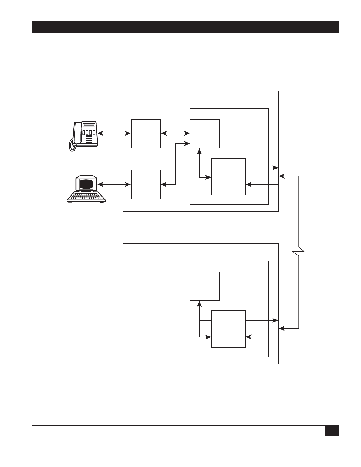
CHAPTER 7: Diagnostics and Troubleshooting
55
Voice/Fax
Figure 7-6. Setting Up a Remote Composite Loopback Test.
Interface
Module
(FXS)
Local Multiserver 500
Digital
Processing Module
Mux
Serial
Interface
Module
Composite
Driver
Remote Multiserver 500
Digital
Processing Module
Mux
Composite
Driver
Page 57

MULTISERVER 500
56
Figure 7-7. Setting Up a Remote Data Loopback Test.
Voice/Fax
Interface
Module
Local Multiserver 500
Digital
Processing Module
Mux
Serial
I/F
Module
Voice/Fax
Interface
Module
Serial
Interface
Module
Composite
Driver
Remote Multiserver 500
Digital
Processing Module
Mux
Composite
Driver
Page 58

CHAPTER 7: Diagnostics and Troubleshooting
57
The remote data loopback test examines the
integrity of the data channel across the link. While
this test is in progress, it does not affect the normal
operation of the voice/fax channel, so you can use
the voice/fax channel to talk about the quality of
the data channel with someone at the other end.
To run the test, see Figure 7-7 and proceed as
follows:
1. Connect an asynchronous terminal to the DATA
CHANNEL connector of the local Multiserver
500.
2. Configure the local data channel for
asynchronous, and configure the asynchronous
channel to match your terminal equipment.
Refer to Chapter 4 or Chapter 5 for
configuration details.
3. Have the remote operator configure his data
channel and asynchronous channel.
4. Put the Multiserver 500 into remote data
loopback. To do this,
a. From the Command Port, enter
>DI REMD <cr>
or
b. From the LCD/keypad, enter through the
Diagnostics menu as shown below:
Main Menu
Diagnostics
Remote Data
5. Type any data on the terminal connected in step
1 and verify that the data is echoed back as
typed.
6. Terminate the remote data loopback test as
described in Section 7.2. Verify that the TM
indicator light goes off.
Page 59

MULTISERVER 500
58
The FXS Voice/Fax Interface Module provides
ringing voltage and battery to the attached
telephone equipment. It is normally used to
connect the voice/fax channel directly to a
telephone instrument or to the line side of a Key
Telephone System or fax machine.
NOTE: The FXS voice/fax interface card is not
registered with the FCC, so it cannot be
connected to a public network.
Figure A-1 shows a typical FXS application. For
clarity, the Multiserver 500 is represented by the
FXS voice/fax interface cards.
There are two versions of the FXS Interface Card:
• MX406C—FXS Standard Loop Start. This
model meets the safety requirements of North
American regulatory agencies.
• MX407C—Enhanced FXS Loop Start. This
model meets the safety requirements of all
European and North American regulatory
agencies.
A.1 Connectors on the Back Panel
Appendix A:
FXS Voice/Fax Interface Module
Figure A-1. A Typical FXS Application.
LOCAL
MULTISERVER 500
FXS
REMOTE
MULTISERVER 500
FXS
Page 60

APPENDIX A: FXS Voice/Fax Interface Module
59
There are two connectors on the back panel of the
FXS interface card: J2 and TB1 (see Figure A-2). J2,
labeled “FXS,” is an RJ-11 modular connector used
in most FXS-type applications. TB1 is an 4-pin
terminal block that connects to a punch block.
Both J2 and TB1 are shielded by a protective cover.
Connectors J2 and TB1 terminate the Tip (T)
and Ring (R) leads in parallel, so that pins 2 and 3
of J2 are connected, respectively, to pins 1 and 2 of
TB1 (see Figure A-3).
In most applications, use a modular cable
(supplied) to connect the voice/fax channel to
telephone equipment. Connect one end of the
cable to the FXS connector on the voice/fax
interface card. Connect the other end to the
telephone equipment.
If you are connecting to a punch block, use the
terminal block (TB1). Use a cable with bare-wire
leads (not included) to connect the terminal block
and the punch block. The terminal block is fitted
with a female plug that serves as a receptacle for the
individual cable leads.
CAUTION!
Wiring to the trunk terminal block must
Figure A-2. Connectors on the Back Panel of the FXS Interface Module.
Figure A-3. Wiring of the Connectors on the Back Panele.
SG — R T
Legend:
J2
4
TB1
321
FXS
SG — R T
R
—
SG
T
=
Tip
=
Ring
=
No Connection
=
Signal Ground
SG — R T
J2
4
TB1
321
FXS
Legend:
T
=
Tip
R
=
Ring
—
=
No Connection
SG
=
Signal Ground
SG — R T
Page 61

MULTISERVER 500
60
be carried out by a qualified technician.
Wires used for this purpose must be
UL
®
type CM, 22/24 AWG, 4-conductor.
Insert each cable lead into the cutout at the front of
the plug and secure it at the top with a small flathead screwdriver. We recommend that you colorcode the cable leads for easy identification.
To make the connection, first remove the female
plug. Then insert each cable lead into the cutout on
the opening at the front of the plug, and secure it at
the top with a screwdriver (see Figure A-4). Finally,
reinsert the plug in the terminal block.
After you make the connection, install the
connector cover: Insert the right tab of the cover in
the retaining slot of the voice/fax interface card’s
Figure A-4. Cable Connections.
Terminal
Block
Back Panel of
Interface Module
Insert
Cable
Lead Here
4SG3—2R1
T
Connector Cover
Modular
Cable
Secure Cable
Leads
Here (4 Places)
Terminal
Block Plug
Right
Tab
Page 62

APPENDIX A: FXS Voice/Fax Interface Module
61
back panel, then secure it on the left side with a
Phillips-head screw.
A.2 Strapping
Do not alter any of the movable straps on the FXS
Interface Module. They are set at the factory to
match the type of memory installed, and changing
the configuration could easily cause the Card to
stop working altogether.
A.3 Removing or Replacing the Module
See Section 3.4 for removal/replacement of the
Multiserver 500 interface modules, including the
FXS interface card.
A.4 Specifications
Signals Supported — Analog voice and Group 3
facsimile (fax)
Fax Signal Types: — V.21 channel 2, V.27 ter 2400,
V.27 ter 4800, V.29 7200, and V.29 9600
Port Impedance —
Enhanced Model (software-selectable):
600 Ω (Default): Matches line impedance of 600
Ω in series with a 2.15-µf capacitor
Complex: Matches line impedance of 370 Ω in
series with a parallel network of a 0.31-µf
capacitor and a 620-Ω resistor
or
220 Ω in series with a parallel network of a 0.12µf capacitor and an 820-Ω resistor
Standard Model:
Fixed at 600 Ω in series with a 2.15-µf capacitor
Insertion Loss — 2 dB nominal @ 1000 Hz (End-
to-End) between Transmit and Receive of Port 1
and Transmit and Receive of Port 2. Example:
Port 1 is FXS LS port and Port 2 is FXO LS port.
Port Return Loss — Echo: ≥22 dB; Singing: ≥18
dB; 200 to 3400 Hz: ≥16 dB
Longitudinal Balance — 200 to 1000 Hz: ≥58 dB;
1000 to 3400 Hz: ≥48 dB
Input and Output Level Adjustments — If you
operate your equipment in the U.S.A. or
Canada, input gain and output attenuation are
set at the factory to 0/0 dBm, and must not be
changed. In other countries, follow the
standards of the country where the equipment is
used.
Maximum Input and Output Levels — 0 dBm
Frequency Response Over the Range of 300 Hz to
3400 Hz — +1 dB/-2 dB with respect to 1000 Hz
Idle Channel Noise — Inband, “C” Message: ≥20
dBrnc; Psofometric: ≥60 dBmpo; Out of band,
10 KHz to 10 MHz Transverse or Longitudinal
Noise: ≤-70 dBm (enhanced models only)
Non-Linear Distortion (Multitone Signal) —
Second Harmonic: ≥40 dB below signal; Third
Harmonic: ≥40 dB below signal
Signal-to-Noise Ratio — ≥37 dB @ 1000 Hz
Echo Suppression — ≥35 dB
Echo Canceling — ≤16 ms (≤1000 km or
600 miles)
Crosstalk (near/far end) Between Channels —
≤75 dB
Signaling — Battery current into 130-W load: ≥36
milliamperes; Battery current into 900-W total
loop: 20 milliamperes minimum
DC Loop Range — ≤900 Ω
DTMF Distortion (AC) — ≤1.5 %
DP Distortion — ≤2 %
Ringing Tone (Software Selectable) — 20 Hz, 25
Hz (default), or 50 Hz
Ringing Voltage (AC load of 2 ringers [4000 W]
and zero line) — 25-Hz Tone:≥54 Vrms ; 20- and
50-Hz Tones: ≥50 Vrms
Ringing Current — ≤15 milliamperes into 5000-Ω
load
Ring Cadence — Repeated ring (matches ringing
cadence from remote voice/fax channel),
interrupted ring 2/4 (2 seconds on, 4 seconds
off), or interrupted ring 2/5 (ring two times for
0.4 separated by 0.2 second, then off for two
seconds)
Page 63

MULTISERVER 500
62
Size — 6.5"W × 6"D (16.5 × 15.2 cm)
Page 64
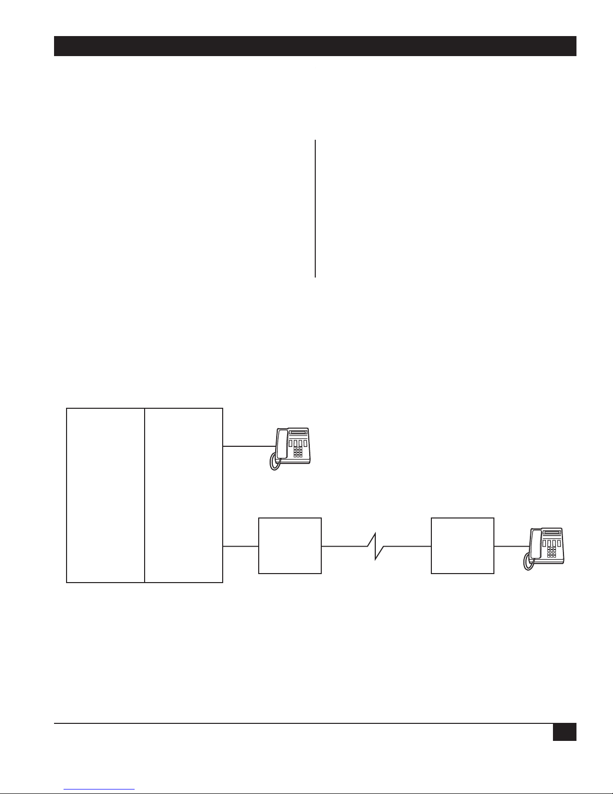
APPENDIX B: FXO Voice/Fax Interface Module
63
The FXO Voice/Fax Interface Module normally
attaches to the station side of a PBX or Central
Office loop start equipment. It lets the PBX station
or central office extend over the Multiserver 500
network to a remote site. Figure B-1 shows a typical
FXO application. For clarity, the Multiserver 500
equipment is represented by the interface modules.
There are two versions of the FXO Voice/Fax
Interface Module:
• MX403C—FXO Standard Loop Start. This
model meets North American regulatory agency
safety requirements.
• MX404C—Enhanced FXO Loop Start. This
model meets all European and North American
regulatory agency safety requirements.
B.1 Connectors on the Back Panel
Appendix B:
FXO Voice/Fax Interface Module
Figure B-1. A Typical FXO Application.
PBX
Trunk
Side
Station
Side
LOCAL
MULTISERVER 500
FXO
REMOTE
MULTISERVER 500
FXS
Page 65

MULTISERVER 500
64
There are two connectors located on the back panel
of the FXO: J2 and TB1 (see Figure B-2). J2,
labeled FXO, is an RJ-11 modular connector used in
most FXO-type applications. TB1 is a 4-pin
terminal block used to connect to a punch block.
Both J2 and TB1 are shielded by a protective cover.
Connectors J2 and TB1 terminate the Tip (T)
and Ring (R) leads in parallel, so that pins 2 and 3
of J2 are connected, respectively, to pins 1 and 2 of
TB1 (see Figure B-3).
In most applications, use a modular cable
(included) to connect the voice/fax channel to
telephone equipment (see Figure B-4). Connect
one end of the cable to the FXO connector on the
voice/fax interface module. Connect the other end
to your telephone equipment.
Figure B-3. Wiring of the Connectors on the Back Panel.
Figure B-2. Back Panel of the FXO Analog Interface Module.
TB1
SG — R T
Legend:
4
321
J2
FXO
R
—
SG
T
=
Tip
=
Ring
=
No Connection
=
Signal Ground
SG — R T
J2 (FXO)
1
2
3
4
1
T
2
3
4
TB1
R
SG
CGND (Chassis Ground)
Page 66
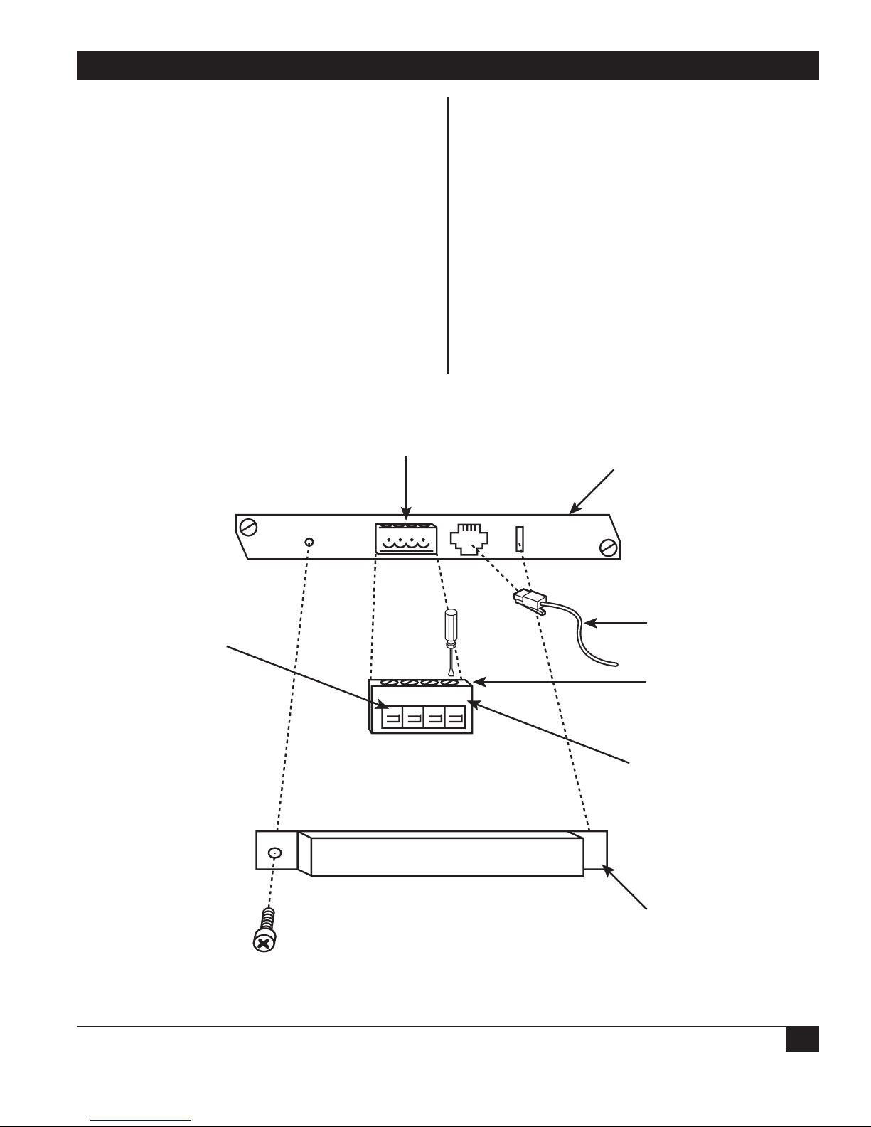
APPENDIX B: FXO Voice/Fax Interface Module
65
If you are connecting to a punch block, use the
terminal block (TB1). Use a cable with bare-wire
leads (not included) to connect the terminal block
and the punch block. The terminal block is fitted
with a female plug that serves as a receptacle for the
individual cable leads.
CAUTION!
Wiring to the terminal block must be
carried out by a qualified technician.
Wires used for this purpose must be
UL type CM, 22/24 AWG, 4-conductor.
Insert each cable lead into the cutout at the front of
the plug and secure it at the top with a small flat-
head screwdriver. We recommend that you color
code the cable leads for easy identification.
Make the connection by first removing the female
plug, inserting each cable lead into the cutout on
the opening at the front of the plug, and securing it
at the top with a screwdriver (see Figure B-4).
Finally, reinsert the plug in the terminal block.
After you make the connection, install the
connector cover. To do this, simply insert the right
tab of the cover in the retaining slot of the
voice/fax interface module back panel. Then
secure on the left side with a Phillips-head screw.
B.2 Strapping
Figure B-4. Cable Connections.
Terminal
Block
Back Panel of
Interface Module
Insert
Cable
Lead Here
4SG3—2R1
T
Connector Cover
Modular
Cable
Secure Cable
Leads
Here (4 Places)
Terminal
Block Plug
Right
Tab
Page 67
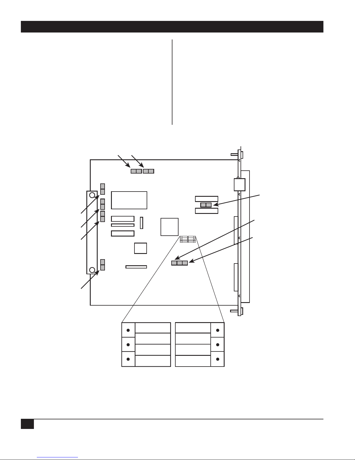
MULTISERVER 500
66
Enhanced FXO Interface Module
There are 12 movable straps located on the
enhanced FXO interface module: E1 through E5
and E7 through E13 (see Figure B-5). Their
functions are as follows:
1. E1 through E5. These straps are reserved for
internal use and are preset at the factory to
match the type of memory installed. You must
not alter them.
2. Dial Pulse Shaping. Dial pulse shaping is
implemented by an RC network connected
across the dial pulse relay U9. To disconnect
the RC network, remove strap E7.
3. Dial Pulse Series Resistance. This option selects
one of two values of the series resistance in the
dial pulse circuit: 150 Ω or 50 Ω (nominal).
The default value is 50 Ω. To select the 150-Ω
value, move the strap from E9 to E8.
4. Line Impedance Selection. This option selects
one of two line-impedance values: 600-Ω
resistive and 600-Ω in series with a 2.15-µf
Figure B-5. Locations of the Straps on the FXO Interface Module.
E2 E1
U2
E13
E5
E4
E3
E7
E10
E11
E12
K1
Strapping
600+2.15µf
(Default)
E8
T1
E9
Block
600
Page 68

APPENDIX B: FXO Voice/Fax Interface Module
67
capacitor (default). To select 600 Ω resistive,
place the strapping block over the right twothirds of E10, E11, and E12 as shown in Figure
B-5. To select 600 Ω in series with a 2.15 µf
capacitor, place the strapping block over the left
two-thirds.
5. E13. This strap is reserved for use in internal
tests. Do not alter it.
Standard FXO Interface Card
Do not alter any of the straps on the standard FXO
interface module. E1 through E5 have the same
function as E1 through E5 in the enhanced model.
E11 has the same function as E13 in the enhanced
model.
B.3 Removing or Replacing the Module
See Section 3.4 for removing or replacing the
Multiserver 500 interface modules, including the
FXO interface module.
B.4 Specifications
Signals Supported — Analog voice, Group 3
facsimile (fax), and modem
Fax Signal Types — V.21 channel 2, V.27 ter 2400,
V.27 ter 4800, V.29 7200, and V.29 9600
Port Impedance —
Enhanced Model (Software-selectable)
600 Ω (Default); may be strapped one of two
ways: 1. Matches line impedance of 600 Ω
resistive; 2. Matches line impedance of 600 Ω in
series with a 2.15-µf capacitor (default)
Complex: Matches line impedance of 370 W in
series with a parallel network of a 0.3-µf
capacitor and a 620-Ω resistor
or
220 Ω in series with a parallel network of a 0.12µf capacitor and an 820-Ω resistor
Standard Model
Fixed at 600 Ω in series with a 2.15-µf capacitor
Insertion Loss — 2 dB nominal @ 1000 Hz (End-
to-End) between Transmit and Receive of Port 1
and Transmit and Receive of Port 2.
Example: Port 1 is FXO LS port and Port 2 is
FXS LS port.
Port Return Loss — Echo Return Loss: ≥22 dB;
Singing Return Loss: ≥18 dB 200 to 3400 Hz:
≥16 dB
Longitudinal Balance — 200 Hz to 1000 Hz: ≥58
dB; 1000 Hz to 3400 Hz: ≥48 dB
Input and Output Levels: — If you operate your
equipment in the U.S.A or Canada, input gain
and output attenuation are set at the factory to
0/0 dBm, and must not be changed. In other
countries, follow the standards of the country
where the equipment is used.
Maximum Input andOutput Levels — 0 dBm
Idle Channel Noise — Inband, “C” Message: ≥20
dBrnc; Psofometric: ≥60 dBmpo; Out of band,
10 KHz to 10 MHz, Transverse or Longitudinal
Noise: ≤70 dBm (enhanced models only)
Non-Linear Distortion, Second and Third
Harmonics (Multitone Signal) — ≥40 dB below
signal level
Signal-to-Noise Ratio — ≥37 dB @ 1000 Hz
Echo Suppression — ≥35 dB
Echo Canceling — ≤16 ms (≤1000 Km or
600 miles)
Crosstalk (near/far end) Between Channels —
≤75 dB
Signaling — DC Pulse Distortion Make/Break: ≤3
%; AC DTMF, Transparently Passed: ≤1.5%
DC Loop Range — 48 V Battery: ≤1750 W; 42.5 V
Battery: ≤1500 W
Off-Hook DC V/I Characteristics at Tip-Ring —
≤300 W
Ringing Voltage Input 18 to 53 Hz — Detect: ≥25
Vrms; Not Detect: ≤ 20 Vrms
Ringing Cadence Repeat Distortion — ≤2 %
Size — 6.5"W × 6"D (16.5 × 15.2 cm)
Page 69

MULTISERVER 500
68
The E&M Voice/Fax Interface Card interfaces the
voice/fax section of the Multiserver 500 with the
trunk side of a Private Branch Exchange (PBX) as
shown in Figure C-1. This type of telephone
interface breaks out the audio signal and status
control (or signaling) on separate wires.
Audio is transmitted on either a single pair
(2-wire operation) of wires labeled T/R, or on two
pairs (4-wire operation) of wires labeled T/R and
T1/R1, as configured. When configured for 2-wire
operation, the T/R pair transmits and receives
communications. When configured for 4-wire
operation, the T/R pair transmits and the T1/R1
pair receives.
Signaling consists of an M lead and an E lead. In
the E&M interface module the M lead is defined as
the input or receive lead and the E lead is defined
as the output or transmit lead. In some cases added
return leads termed SB and SG are used.
There are five E&M signaling formats defined:
Types I, II, III, IV, and V. However, only three
formats are in common use today: Types I, II, and V.
Type I is the most common type used in the United
States, while Type V is common throughout the rest
of the world. Type II was designed for compatibility
with some AT&T
®
PBX types.
C.1 Differences Between Models
There are two versions of the E&M Voice/Fax
Interface Card:
• MX401C—E&M Standard. This model meets all
North American regulatory-agency safety
requirements. It uses the Type I signaling
convention.
• MX402C—E&M Enhanced. This model meets
all European and North American regulatoryagency safety requirements. You may strap it
one of three ways to match the signaling
convention of the interfacing PBX equipment:
Type I, II, or V.
Unless specified otherwise, information in this
appendix applies to both models.
Appendix C:
E&M Voice/Fax Interface Module
Figure C-1. Connections for the E&M Voice/Fax Interface Module.
PBX
Trunk
Station
Side
Side
E
M
T
R
T1
R1
MULTISERVER 500
E
M
T
R
E&M
Interface
Module
T1
R1
Page 70
APPENDIX C: E&M Voice/Fax Interface Module
69
C.2 Telephone-Interface Connectors
The telephone interface signals are terminated in
an 8-pin tie trunk terminal block on the back panel
(see Figure C-2). This connector is fitted with a
female plug.
C.3 Connecting the Telephone-Interface Cable
To connect to the telephone interface (PBX), see
Figure C-3 (page 70) and proceed as follows:
WARNING!
Remove the power plug from the power
socket BEFORE you make any connections to the telephone interface.
CAUTION!
Wiring to the tie trunk terminal block
must be carried out by a qualified
technician. Wires used for this purpose must be UL type CM, 22/24 AWG,
8-conductor.
1. Remove the plug from the 8-pin terminal block.
2. Use a cable with bare-wire leads (not included).
Insert each cable lead into the cutout at the
front of the plug and secure it with a small flathead screwdriver at the top. We recommend
that you color-code the cable leads for easy
identification.
3. Insert the plug, which now includes the cable
leads, in the terminal block.
4. After you make the connection, install the
connector cover: Insert the right tab of the
cover in the retaining slot of the voice/fax
interface module back panel; then secure it on
the left side with a Phillips-head screw.
C.4 E&M Lead States
Figure C-2. Connectors on the Back Panel.
SB E M SG
8 765
SB E M SG
R T R1 T1
4 321
R T R1 T1
Page 71

MULTISERVER 500
70
Figure C-3. Connecting the E&M Cable.
Terminal
Block
87654321
SB M E SG R1 T1 R T
Back Panel of
Interface Module
Insert
Cable
Lead Here
SB
M E SG R1 T1 R T
Connect to PBX
(Figures C-4 through C-6)
Connector Cover
Secure Cable Leads
Here (8 Places)
Terminal
Block Plug
Right
Tab
Page 72

APPENDIX C: E&M Voice/Fax Interface Module
71
Table C-1 is a summary of the E and M idle and
active lead states for signaling Types I, II, and V.
C.5 Connection Diagrams
Figures C-4 through C-6 are simplified connection
diagrams between the E&M voice/fax interface
module and the PBX for signaling types I, II, and V.
As discussed earlier, Types II and V are supported
only by the MX402C.
Table C-1. E&M Lead States
Lead State Type I Type II Type V
E (output) Idle Open Open Open
Active SG Close (SG) SG
M (input) Idle SG Open Open
Active -48 V Close (SB) SG
SG = Signal Ground
SB = Signal Battery
Page 73

MULTISERVER 500
72
Figure C-4. Type I Interface Connection.
PBX
E&M Interface Module
Strapped for Type I
-48V
4-wire
Operation
Detector
2-wire
Operation
M
GND
E
T
R
T1
R1
M
SG
T
R
T1
R1
Detector
E14
E
E15
1µf
C36
+
E8
C36
+
E17
Page 74

APPENDIX C: E&M Voice/Fax Interface Module
73
PBX
Figure C-5. E&M Type II Interface Connection.
E&M Interface Module
Strapped for Type II
E16
SB SB
-36V
-48V
4-wire
Operation
Detector
2-wire
Operation
M
GND
E
T
R
T1
R1
M
SG
R
T1
R1
Detector
E14
E
E15
1µf
T
C36
+
E8
C36
+
E17
Page 75

MULTISERVER 500
74
Figure C-6. E&M Type V Interface Connection.
E&M Interface Module
Strapped for Type V
PBX
SB SB
E&M Interface Module
Strapped for Type II
E16
-48V
4-wire
Operation
Detector
2-wire
Operation
M
GND
E
T
R
R1
T1
M
SG
T1
R1
R
Detector
-36V
E14
E
E15
1µf
C36
+
T
E8
C36
+
E17
Page 76
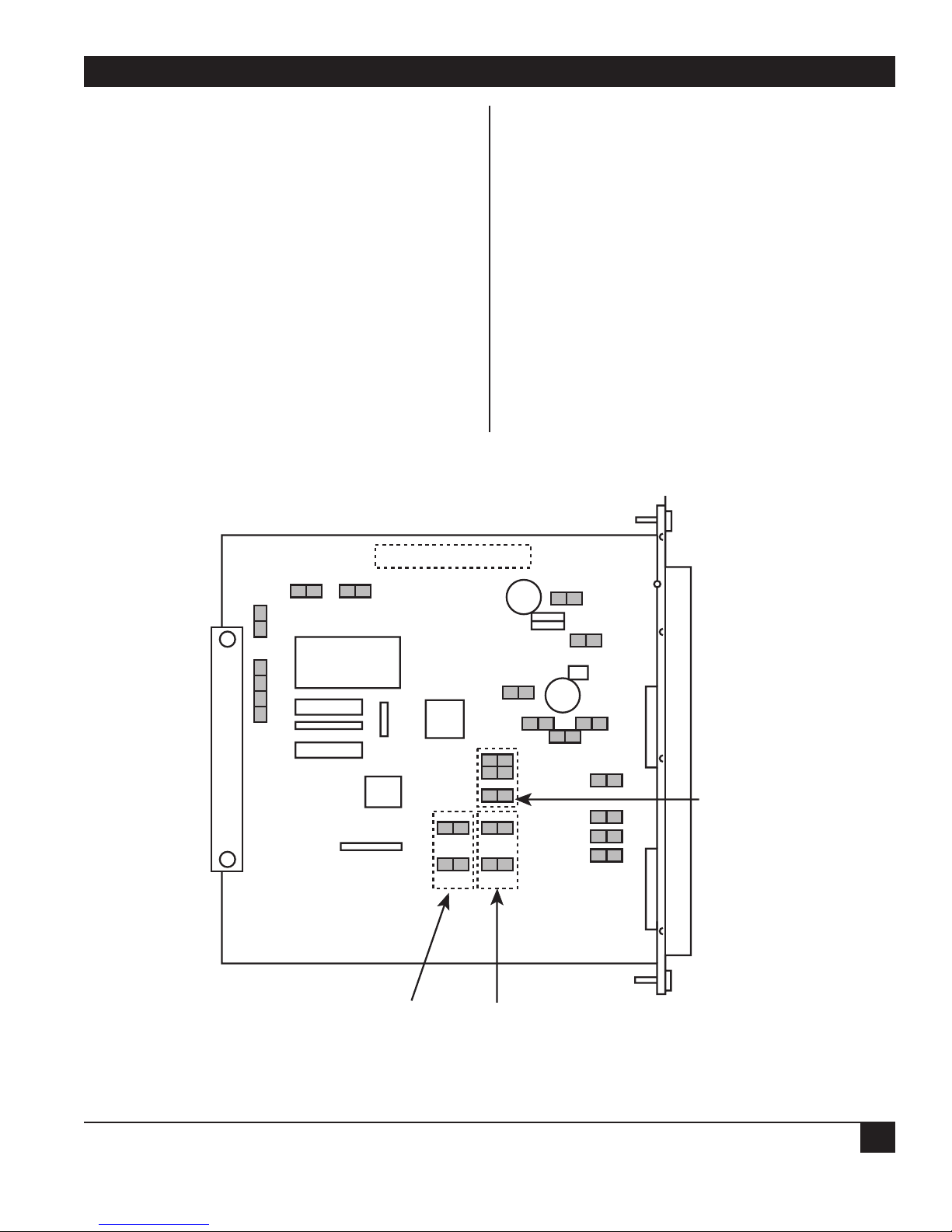
APPENDIX C: E&M Voice/Fax Interface Module
75
C.7 Strapping
Enhanced E&M Voice/Fax Interface Card
The functions of straps E1 through E22 on the
enhanced E&M interface card (see Figure C-7) are
as follows:
1. E1 through E5. These straps are preset at the
factory to match the type of memory installed.
Do not alter them.
2. E6, E7, and E9 through E13. These straps are
used to select signaling types I, II, and V
(MX402C only).
3. Straps E8 and E17 are normally installed to
shunt out DC blocking capacitors C36 and C38.
Remove them if there are DC voltages present in
the R and R1 leads.
4. Strap E14 is used to shunt out the series resistor
in the E lead in case the loop resistance is too
high to trip the detector inside the PBX.
5. Strap E15 is used for dial-pulse correction; it
connects a 1-µF filter capacitor between the SG
lead and ground.
6. Strap E16 is used to shunt out the series resistor
in the SB lead in case the loop resistance is too
high to trip the detector inside the interface
module.
7. Straps E18 and E19 are reserved for use in
internal tests. Do not alter them.
8. Straps E20, E21, and E22 are spares.
Figure C-7. Where the Straps Are on the E&M Module.
S/N
E2 E1
E5E4E3
E17C38
E18
E6
E7
TYPE I
E8
E14 E15
E9
E10
E11
TYPE II
E12
E13
C36
E16
E19
E20
E21
E22
TYPE V
Page 77

MULTISERVER 500
76
Standard E&M Voice/Fax Interface Card
The functions of the straps on the standard E&M
voice/fax interface module are as follows:
1. E1 through E-5 have the same functions as E1
through E5 in the enhanced model.
2. E9 has the same function as E14 in the
enhanced model.
3. E6 and E7 have the same functions as E18 and
E19 in the enhanced model.
4. E8 is a spare in the standard model.
C.7 Removing or Replacing the Module
See Section 3.4 for removal/replacement of the
Multiserver 500 interface modules, including the
E&M interface module.
C.8 Specifications
Signals supported — Analog voice and Group 3
facsimile (fax)
Fax Signal Types — V.21 channel 2, V.27 ter 2400,
V.27 ter 4800, V.29 7200, and V.29 9600
Port Impedance —
4-wire, and 2-wire Standard Models: Matches line
impedance of 600 Ω resistive.
2-wire (Enhanced model only, software selectable: 600
Ohms (Default): Matches line impedance of 600
Ω resistive; Complex: Matches line impedance
of 370 Ω in series with a parallel network of a
0.31-µf capacitor and a 620W resistor, or 220 Ω
in series with a parallel network of a 0.12-µf
capacitor and a 620 Ω resistor
Port Return Loss — Echo Return Loss: ≥22 dB;
Singing Return Loss: ≥18 dB; 200 to 3400 Hz:
16 dB
Longitudinal Balance — Up to 1000 Hz: ≥58 dB;
1000 Hz to 3400 Hz:≥48 dB
Input and Output Level Adjustments — If you
operate your equipment in the U.S.A. or
Canada, input gain and output attenuation are
set at the factory to 0/0 dBm, and must not be
changed. In other countries, follow the
standards of the country where the equipment is
used.
Maximum Input Level — 0 dBm
Maximum Output Level (Enhanced Model) — 4-
wire: + 7 dBm; All others: 0 dBm
Insertion Loss at 1000 Hz — 2-wire T/R of Port 1
to 2-wire T/R of Port 2: 2 dB nominal; 4-wire
T/R of Port 1 to 4-wire T1/R1 of Port 2: 2 dB
nominal
Frequency Response Over the Range of 304 Hz to
3404 Hz — +1 dB/-2 dB with respect to 1004 Hz
Idle Channel Noise — Inband “C” Message: ≤ 20
dBrnc/65 dBmpo; Psofometric: ≤ 65 dBrnc/65
dBmpo; Out of band, 10 KHz to 10 MHz
Transverse or Longitudinal Noise — ≤-70 dBm
(enhanced models only)
Non-Linear Distortion (Multitone Signal), Second
and Third Harmonics — ≥40 dB below signal
level
Signal-to-Noise Ratio at 1004 Hz — ≥37 dB
Echo Suppression (2-wire) — ≥35 dB
Echo Canceling (2-wire) — ≤16 ms (≤1000 km or
600 miles)
Loop Range Including Instrument — ≤900 ohms;
1372 m (4500 feet) on 24 AWG wire pair
Signaling — E-Lead Current Limit: ≤ 25 ma; M-
Lead Sensitivity: ≤1400 ohms DC Pulse
Distortion: ≤2%
Signaling Formats — AC: DTMF @ 2280 Hz
(AC15, 4-wire); DC: Steady or Pulsed
Types — Enhanced Model: Types I, II, and V;
Standard Model: Type I only
Size — 6.5"W × 6"D (16.5 × 15.2 cm)
Page 78

APPENDIX D: Changing the Data Interface Types
77
You can configure the DATA CHANNEL and
COMPOSITE interface connectors to give one of
three types of signal levels: RS-232, V.35, or RS-530.
Configuration is implemented by a set of
daughterboards and jumper blocks.
A fourth interface type, RS-449, can be derived
from an RS-530 interface type using special
converter cables. A fifth composite interface type,
X.21, may be derived from an RS-530 type using
X.21 special converter cables. Refer to Appendix F
for cabling details.
Both interface connectors are configured at the
factory to signal-level types specified with the order.
If you need to change the interface type of either or
both connectors, read the rest of this appendix.
WARNING!
To change interface types, you must
remove the top cover in order to gain
access to the interior of the Multiserver
500. Do NOT attempt to remove the top
cover while the Multiserver 500 is
connected to the power source.
Appendix D:
Changing the Data Interface Types
Figure D-1. Removing the Top Cover.
MULTISERVER 500
EXE
PO
IS
TD
RD
LS
RS
VA
TM
(4 Places)
Page 79

MULTISERVER 500
78
CAUTION!
Observe standard industry practices
concerning the handling of staticsensitive electronic components. Use
suitable grounding for the unit, in your
work area, and on your person.
D.1 Removing the Top Cover
Items used to configure the interface types are
located on the top module and are accessible when
the top cover is removed. The top cover is fastened
by four screws, two on each side. Remove and save
the four screws, using a number 1 or number 2
Phillips-head screwdriver; then lift off the cover.
See Figure D-1.
D.2 Configuring the Interfaces
Composite Interface
Table D-1 is a configuration matrix for the
composite interface. The column headings in
Table D-1 relate to items highlighted in Figure D-2.
To configure an interface type, first consult Table D1 to determine the requirements for that interface.
Then, find the locations of the items associated with
that interface and install (or remove) as necessary.
For example, to configure the composite
interface for V.35, move down the Interface Type
column in Table D-1 to V.35, and check all columns
along that row. You will note that the Model
MX410C-V.35 daughterboard must be installed,
headers X3 and X4 must be removed, and jumper
E11 and E4 must be installed on pins 1-2. You will
also find that the interface cable number required
for this interface is EHN070.
Finally, install or remove the applicable items,
using Figure D-1 as a guide.
Data Channel Interface
Table D-1. List of Configuration Items for the Composite Interface
Interface Daughterboard Cable Headers Jumper Jumper
Type A B X3 and X4 E11 E4
RS-232 None EZ423 Installed Installed Installed
crossover on pins on pins
2-3 1-2
V.35 Model EHN070 Removed Installed Installed
MX410C-V.35 crossover on pins on pins
1-2 1-2
RS-530 Model EHN077-005M Removed Installed Installed
MX410C-422 crossover on pins on pins
2-3 1-2
RS-449 Model EHN075-005M Removed Installed Installed
MX410C-422 crossover on pins on pins
2-3 1-2
X.21 Model EHN073-005M Removed Installed Installed
MX410C-422 crossover on pins on pins
2-3 2-3
Page 80

APPENDIX D: Changing the Data Interface Types
79
E4
Figure D-2. Configuring the Composite Interface.
E4
J9
E5
J11 J10
E11
X3 and X4
3
2
E4
1
3
2
1
A
B
E11
J8
123
123
E11
Page 81

MULTISERVER 500
80
To configure the data channel interface, consult
Table D-2 and Figure D-3 and follow the guidelines
given for the composite interface.
Interface Daughterboard Cable D Headers Jumper
Type C X2 and X5 E10
RS-232 None EDN16C Installed Installed on pins 2-3
straight
V.35 Model EHN071 Removed Installed on pins 1-2
MX410C-V.35 straight
RS-530 Model EHN076-005M Removed Installed on pins 2-3
MX410C-422 straight
RS-449 Model EHN074-005M Removed Installed on pins 2-3
MX410C-422 straight
X.21 Model EHN072-005M Removed Installed on pins 2-3
MX410C-422 straight
Table D-2. List of Configuration Items for the Data Channel Interface
D.3 Replacing the Top Cover
After you configure the interface connectors,
replace the top cover and secure it with the four
screws removed in Section D.1.
Page 82

APPENDIX D: Changing the Data Interface Types
81
E4
Figure D-3. Configuring the Data-Channel Interface.
E5
X2 and X5
123
E11
J9
J11 J10
123
E11
J8
C
E10
D
Page 83

MULTISERVER 500
82
Information provided in the following paragraphs is
applicable only to Multiserver 500 units installed in
the U.S.A. and Canada. If your installation is
located outside of the U.S.A. and Canada, you must
meet the requirements of the country where the
equipment is operated.
E.1 Requirements for Operation with the
Telephone Company
If your equipment causes harm to the telephone
network, the telephone company may temporarily
discontinue your service. If possible, the company
will notify you in advance. But if advance notice is
not practical, you will be notified as soon as
possible. You will be given the opportunity to
correct the situation and you will be informed of
your right to file a complaint with the FCC.
Your telephone company may make changes in its
facilities, equipment, operation, or procedures that
could affect the proper functioning of your
equipment. If it does, you will be notified in
advance to give you an opportunity to maintain
uninterrupted service.
If you experience any operational problems while
you’re using your equipment, determine whether
the problem is due to a malfunction in your
equipment or in the telephone interface.
WARNING!
Do not attempt to repair the Multiserver
500. Attempts to repair the Multiserver
500 may cause injury, and may also
damage equipment on the telephone
network.
Attempts to repair the Multiserver 500 are
violations of FCC rules. Repair to the Multiserver
500 can only be made by the manufacturer, its
authorized agents, and by others who may be
authorized by the FCC. Please contact our
Technical Support Staff for further information.
1. The problem may be in the telephone interface.
If the Multiserver 500 works in some interfaces
but not in others, the problem is due to the
telephone interface.
2. The problem may be in your equipment. If the
Multiserver 500 does not work with any
telephone interface, then it is most likely that
the problem is in your Multiserver 500. To
check your Multiserver 500, follow the test
procedures outlined in Chapter 7.
E.2 Equipment Attachment Limitations for
Operation in Canada
CP-01, Part I
Section 10.1
Notice: The Canadian Department of
Communications label identifies certified
equipment. This certification means that the
equipment meets certain telecommunications
network protective, operational and safety
requirements. The Department does not guarantee
the equipment will operate to the user’s satisfaction.
Before installing this equipment, the user should
ensure that it is permissible to be connected to the
facilities of the local telecommunications company.
The equipment must also be installed using an
acceptable method of connection. In some cases,
the company’s inside wiring associated with a single
line individual service may be extended by means of
a certified connector assembly (telephone
extension cord). The customer should be aware
that compliance with the above conditions may not
prevent degradation of service in some situations.
Repairs to certified equipment should be made
by an authorized Canadian maintenance facility
designated by the supplier. Any repairs or
alterations made by the user to this equipment, or
equipment malfunctions, may give the
telecommunications company cause to request the
user to disconnect the equipment.
Users should ensure for their own protection that
the electrical ground connections of the power
utility, telephone lines and internal metallic water
pipe system, if present, are connected together. This
Appendix E: Agency and
Telephone-Company Requirements
Page 84

APPENDIX E: Agency and Telephone-Company Requirements
83
precaution may be particularly important in rural
areas.
CAUTION!
You should NOT attempt to make such
connections yourself, but should
contact the electric inspection
authority or electrician, as appropriate.
CP-01, Part I,
Section 10.2
Notice: The Load Number (LN) assigned to each
terminal device denotes the percentage of the total
load to be connected to a telephone loop which is
used by the device, to prevent overloading. The
termination on a loop may consist of any
combination of devices subject only to the
requirement that the total of the Load Numbers of
all the devices does not exceed 100.
Page 85

MULTISERVER 500
84
IMPORTANT!
The composite and data channel
connectors require shielded cables in
order to maintain compliance with Title
47 of the Code of Federal Regulations,
Federal Communications Commission’s Rules and Regulations, Part 15,
Subpart J.
This Appendix contains cabling diagrams and pin
assignments for the COMPOSITE, DATA
CHANNEL, and CMD PORT interface connectors.
Refer to the diagrams if you intend to construct
your own cables. Cable length must not exceed 50
feet (15 meters).
Cabling for the voice/fax channel depends on
the type of interface module installed in the
Multiserver 500, and is given in Appendixes A, B,
and C.
F.1 Cables for the Composite Interface
RS-232-to-RS-232 DCE
Pin assignments for the COMPOSITE and DATA
CHANNEL connectors configured for RS-232 signal
levels are shown in Figure F-1. Use a crossover
cable (order code EZ423-0015), with male
terminations at each end, for connection to a DCE
device. See Figure F-2.
Appendix F: Cabling and Pin Assignments
Figure F-1. Pin Assignments for the RS-232 COMPOSITE and DATA CHANNEL Connectors.
1
2
3
4
GROUND
TD
RD
RTS
5
6
7
8
11
15
17
18
20
22
24
25
CTS
DSR
SIGNAL GROUND
RLSD
UNASSIGNED
TX CLOCK
RX CLOCK
EXTERNAL RX CLOCK
DTR
RI
EXTERNAL TX CLOCK
BUSY
PIN 13
PIN 25
PIN 1
DCE
PIN 14
Page 86

APPENDIX F: Cabling and Pin Assignments
85
PIN 1
Figure F-2. RS-232-to-RS-232 DCE Crossover Cable (EZ423-0015).
25-PIN CONNECTOR
(MALE)
25-PIN CONNECTOR
(MALE)
GROUND
TD
RD
RTS
CTS
DSR
SIGNAL GROUND
RLSD
UNASSIGNED
TX CLOCK
RX CLOCK
EXTERNAL RX CLOCK
DTR
RI
EXTERNAL TX CLOCK
1
2
3
4
5
6
7
8
11
15
17
18
20
22
24
1
3
2
8
11
20
7
4
5
18
24
15
6
25
17
BUSY
TO MULTISERVER
COMPOSITE CONNECTOR
25
22
TO DCE
DEVICE
Page 87

MULTISERVER 500
86
V.35-to-DCE
Pin assignments for the COMPOSITE and DATA
CHANNEL connector configured for V.35 signal
levels are shown in Figure F-3 Use a crossover cable
with male terminations at each end. See Figure F-4.
RS-530-to-RS-530 DCE
Figure F-3. Pin Assignments for the V.35 COMPOSITE and DATA CHANNEL Connectors.
19
18
24
23
17
16
20
11
13
3
4
2
1
6
8
RD A
RD B
SER. CLK. RX EXT A
SER. CLK. RX EXT B
TD A
TD B
SER. CLK. TX EXT A
SER. CLK. TX EXT B
SER. CLK. RX A
SER. CLK. TX B
DTR
DSR
RLSD
UNASSIGNED
RTS
PIN 13
PIN 25
PIN 1
DCE
PIN 14
25
25
5
22
15
14
7
BUSY IN
CTS
RI
SER. CLK. TX A
SER. CLK. TX B
SIGNAL GROUND
Page 88
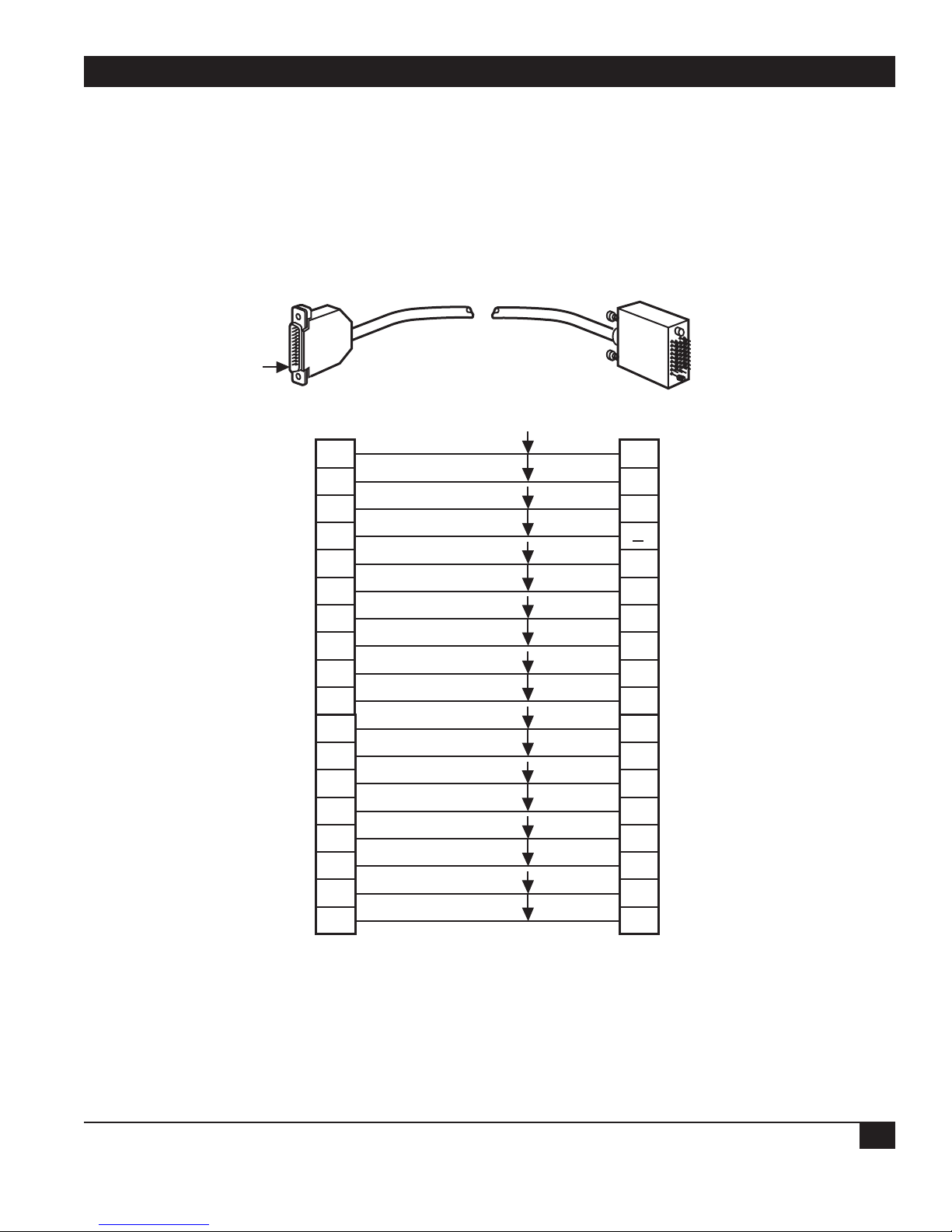
APPENDIX F: Cabling and Pin Assignments
87
PIN 1
Figure F-4. V.35-to-DCE Crossover Cable (EHN070-005M).
DB25 CONNECTOR
RD A
RD B
SER. CLK. RX EXT. A
SER. CLK. RXEXT. B
TD A
TD B
SER. CLK. TX EXT. A
SER. CLK. TX EXT. B
SER. CLK. RX A
SER. CLK. RX B
DTR
DSR
RLSD
UNASSIGNED
RTS
P1 (MALE)
3
4
19
18
2
1
24
23
17
16
20
6
8
11
13
V.35 CONNECTOR
P2 (MALE)
TD A
P
TD B
S
SER. CLK. TXA
Y
a
SER. CLK. TXB
RD A
R
RD B
T
SER. CLK. RX A
V
SER. CLK. RX B
X
SER. CLK. TX EXT. A
U
SER. CLK. TX EXT. B
W
DSR
E
DTR
H
RTS
C
UNASSIGNED
D
RLSD
F
BUSY IN
RI
SIGNAL GROUND
TO MULTISERVER
COMPOSITE CONNECTOR
25
22
RI
J
BUSY IN
K
7
TO DCE INTERFACE
SIGNAL GROUND
B
Page 89

MULTISERVER 500
88
Pin assignments for the COMPOSITE and DATA
CHANNEL connectors configured for RS-530 signal
levels are shown in Figure F-5. Use a crossover
cable (order code TC) with male terminations at
each end to connect to an RS-530 DCE device. See
Figure F-6.
RS-530-to-RS-449 DCE Crossover Cable
Figure F-5. Pin Assignments for the RS-530 COMPOSITE and DATA CHANNEL Connectors.
2
14
3
16
8
10
4
19
18
21
24
11
17
9
20
TD A
TD B
RD A
RD B
RLSD A
RLSD B
RTS A
RTS B
DTE TSET A
DTE TSET B
DTE TSET A
DTE TSET B
DCE RSET A
DCE RSET B
DTER A
PIN 13
PIN 25
PIN 1
DCE
PIN 14
23
6
22
15
12
25
7
1
DTER B
DCER A
DCER B
DCE TSET A
DCE TSET B
TM
SIGNAL GROUND
SHIELD
Page 90

APPENDIX F: Cabling and Pin Assignments
89
Figure F-6. RS-530-to-RS-530 DCE Crossover Cable.
PIN 1 PIN 1
DB25 CONNECTOR
P1 (MALE)
TD (A)
TD (B)
RD (A)
RD (B)
RLSD (A)
RLSD (B)
RTS (A)
RTS (B)
DTE-RSET (A)
DTE-RSET (B)
DTE-TSET (A) DCE-RSET (A)
DTE-TSET (B)
DCE-RSET (A)
DCE-RSET (B)
DTER (A)
2
14
3
16
8
10
4
19
18
21
24
11
17
9
20
DB25 CONNECTOR
P2 (MALE)
RD (A)
3
RD (B)
16
TD (A)
2
TD (B)
14
RTS (A)
4
RTS (B)
19
RLSD (A)
8
RLSD (B)
10
DCE-TSET (A)
15
DCE-TSET (B)
12
17
DCE-RSET (B)
9
DTE-RSET (A)
24
DTE-RSET (B)
11
DCER (A)
6
DTER (B)
DCER (A)
DCER (B)
SIGNAL GROUND
SHIELD
COMPOSITE CONNECTOR
23
22
TO MULTISERVER
DCER (B)
22
6
7
1
TO DCE
INTERFACE
DTER (A)
20
DTER (B)
23
SIGNAL GROUND
7
SHIELD
1
Page 91

MULTISERVER 500
90
Pin assignments for the COMPOSITE and DATA
CHANNEL connectors configured for RS-530 signal
levels are shown in Figure F-5. Use a crossover cable
(order number EHN075-005M) with male
terminations at each end to connect to an RS-449
DCE device. See Figure F-7.
RS-530-to-X.21 DCE Crossover Cable
Figure F-7. RS-530-to-RS-449 DCE Crossover Cable.
PIN 1
DB25 CONNECTOR
P1 (MALE)
TD (A)
TD (B)
RD (A)
RD (B)
RTS (A)
RTS (B)
DCER (A)
2
14
3
16
4
19
6
DB37 CONNECTOR
P2 (MALE)
RD (A)
6
RD (B)
24
SD (A)
4
SD (B)
22
RR (A)
13
RR (B)
31
TR (A)
12
DCER (B)
RLSD (A)
RLSD (B)
DTE-RSET (B) TT (A)
DCE-RSET (B)
DTE-RSET (A)
DTE-RSET (B)
DTER (A)
DTER (B)
DTE-TSET (A)
DTE-TSET (B)
SHIELD
SIGNAL GND
TM.
22
8
10
17
9
18
21
20
23
24
11
1
7
25
TR (B)
30
RS (A)
7
RS (B)
25
17
TT (B)
35
ST (A)
5
ST (B)
23
DM (A)
11
DM (B)
29
RT (A)
8
RT (B)
26
SHIELD
1
SIGNAL GROUND
19
RC
20
SC
37
TM
18
TO MULTISERVER
COMPOSITE CONNECTOR
TO DTE
INTERFACE
Page 92
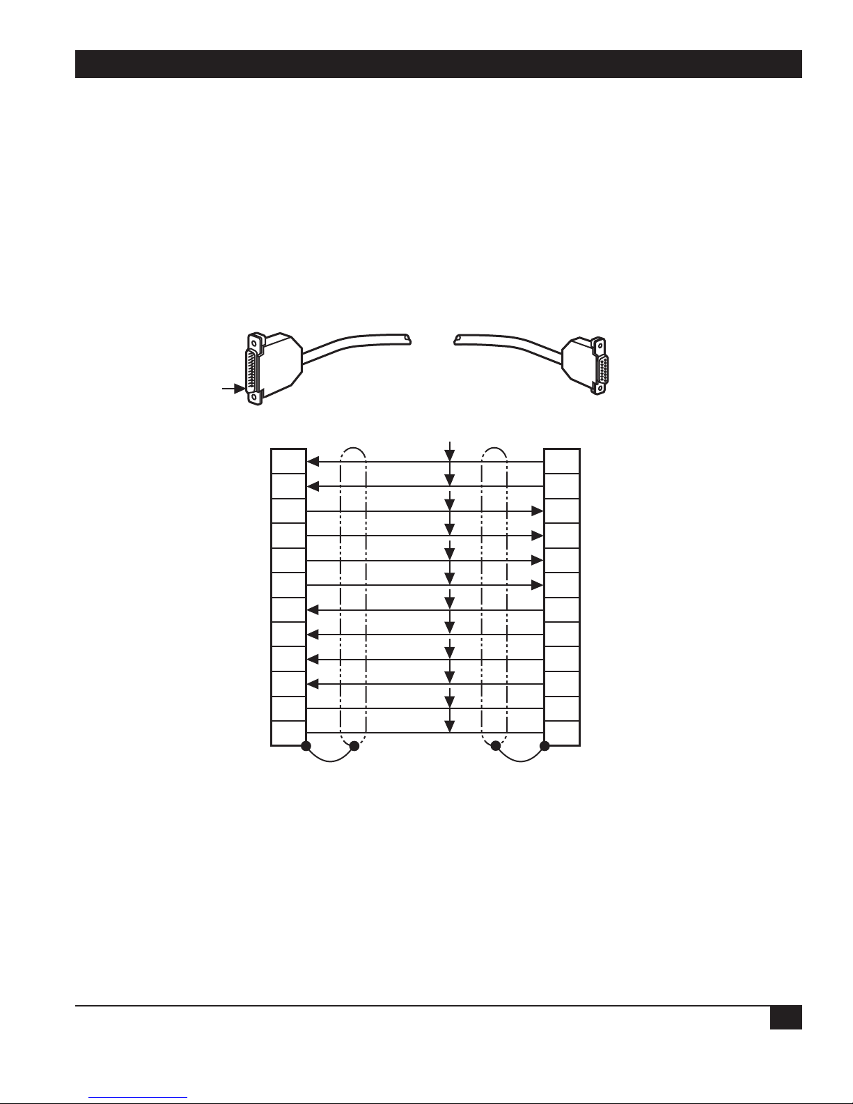
APPENDIX F: Cabling and Pin Assignments
91
Pin assignments for the COMPOSITE connector
configured for RS-530 signal levels are shown in Figure
F-5. Use a crossover cable (order code EHN073-005M)
with male terminations at each end to connect to an
X.21 DCE device. See Figure F-8.
Figure F-8. RS-530-to-X.21 DCE Crossover Cable.
PIN 1
DB25 CONNECTOR
TD (A)
TD (B)
RD (A)
RD (B)
RLSD (A)
RLSD (B)
RTS (A)
RTS (B)
DTE-TST (A)
DTE-TST (B)
SIGNAL GROUND
SHIELD
TO MULTISERVER
COMPOSITE CONNECTOR
P1 (MALE)
2
14
3
16
8
10
4
19
24
11
7
1
DB15 CONNECTOR
P2 (FEMALE)
RD (A)
4
RD (B)
11
TD (A)
2
TD (B)
9
RTS (A)
3
RTS (B)
10
RLSD (A)
5
RLSD (B)
12
DCE-RST (A)
6
DCE-RST (B)
13
SIGNAL GROUND
8
SHIELD
1
TO DCE
INTERFACE
Page 93

MULTISERVER 500
92
F.2 Data-Channel Interface Cables
RS-232 to DTE
Pin assignments for the DATA CHANNEL
connector configured for RS-232 signal levels are
shown in Figure F-1. Use a straight cable (order
code EDN16C-xxxx-MF) with male-to-female
terminations. See Figure F-9.
Figure F-9. RS-232-to-DTE Straight Cable (EDN16C-xxxx-MF).
PIN 1
25-PIN CONNECTOR
(MALE)
25-PIN CONNECTOR
(FEMALE)
GROUND
TD
RD
RTS
CTS
DSR
SIGNAL GROUND
RLSD
UNASSIGNED
TX CLOCK
RX CLOCK
EXTERNAL RX CLOCK
DTR
RI
EXTERNAL TX CLOCK
1
2
3
4
5
6
7
8
11
15
17
18
20
22
24
GROUND
1
TD
2
RD
3
RTS
4
CTS
5
DSR
6
SIGNAL GROUND
7
RLSD
8
UNASSIGNED
11
15
17
18
20
22
24
TX CLOCK
RX CLOCK
EXTERNAL RX CLOC
DTR
RI
EXTERNAL TX CLOC
BUSY
TO MUTISERVER
DATA CHANNEL CONNECTOR
25
25
TO DTE
INTERFACE
BUSY
Page 94

APPENDIX F: Cabling and Pin Assignments
93
V.35 to DTE
Pin assignments for the DATA CHANNEL
connector configured for V.35 signal levels are
shown in Figure F-3. Use a straight cable (order
code EHN071-005M) with male-to-female
terminations. See Figure F-10.
Figure F-10. V.35-to-DTE Straight Cable (EHN071-005M)
PIN 1
DB25 CONNECTOR
TD A
TD B
SER. CLK. TX A
SER. CLK. TX B
RD A
RD B
SER. CLK. RX A
SER. CLK. RX B
SER. CLK. TX. EXT A
SER. CLK. TX. EXT B
DSR
DTR
RTS
CTS
RLSD
P1 (MALE)
2
1
15
14
3
4
17
16
24
23
6
20
13
5
8
V.35 CONNECTOR
P2 (FEMALE)
TD A
P
TD B
S
SER. CLK. TX A
Y
a
SER. CLK. TX B
RD A
R
RD B
T
SER. CLK. RX A
V
SER. CLK. RX B
X
SER. CLK. TX. EXT A
U
SER. CLK. TX. EXT B
W
DSR
E
DTR
H
RTS
C
CTS
D
RLSD
F
RI
22
BUSY
SIGNAL GROUND
TO MULTISERVER
DATA CHANNEL CONNECTOR
25
RI
J
BUSY
K
7
TO DTE
INTERFACE
SIGNAL GROUND
B
Page 95

MULTISERVER 500
94
RS-530-to-RS-530 DTE
Pin assignments for the DATA CHANNEL connector
configured for RS-530 signal levels are shown in
Figure F-5. Use a straight cable (order code
EHN076-005M) with male-to-female terminations, to
connect to an RS-530 DTE device. See Figure F-11.
Figure F-11. RS-530-to-RS-530 DTE Straight Cable.
PIN 1
DB25 CONNECTOR
P1 (MALE)
TD (A)
TD (B)
RD (A)
RD (B)
RTS (A)
RTS (B)
CTS (A)
CTS (B)
2
14
3
16
4
19
5
13
PIN 1
DB25 CONNECTOR
P2 (FEMALE)
TD (A)
2
TD (B)
14
RD (A)
3
RD (B)
16
RTS (A)
4
RTS (B)
19
CTS (A)
5
CTS (B)
13
DCER (A)
DCER (B)
RLSD (A) RLSD (A)
RLSD (B)
DCE-RSET (A)
DCE-RSET (B)
DCE-TSET (A)
DCE-TSET (B)
DTER (A)
DTER (B)
DTE-TSET (A)
DTE-TSET (B)
DTE-RSET (A)
DTE-RSET (B)
SIGNAL GROUND
SHIELD
SHIELD
22
10
17
15
12
20
23
24
11
18
21
6
8
9
7
1
DCER (A)
6
DCER (B)
22
8
RLSD (B)
10
DCE-RSET (A)
17
DCE-RSET (B)
9
DCE-TSET (A)
15
DCE-TSET (B)
12
DTER (A)
20
DTER (B)
23
DTE- TSET (A)
24
DTE-TSET (B)
11
SIGNAL GROUND
7
SHIELD
1
TO MULTISERVER
DATA CHANNEL CONNECTOR
TO DTE
INTERFACE
Page 96

APPENDIX F: Cabling and Pin Assignments
95
RS-530-to-RS-449 DTE
Pin assignments for the DATA CHANNEL
connector configured for RS-530 signal levels are
shown in Figure F-5. Use a straight cable (order
code EHN074-005M) with male-to-female
terminations, to connect to an RS-449 DTE device.
See Figure F-12.
DB25 CONNECTOR
P1 (MALE)
DB37 CONNECTOR
P2 (FEMALE)
RLSD (A) RR (A)
RLSD (B)
2
14
3
16
4
19
5
13
6
22
4
22
6
24
7
25
9
27
11
29
DCER (B)
DCER (A)
CTS (B)
CTS (A)
RTS (B)
RTS (A)
RD (B)
RD (A)
TD (B)
TD (A)
DM (B)
DM (A)
CS (B)
CS (A)
RS (B)
RS (A)
RD (B)
RD (A)
SD (B)
SD (A)
8
10
13
31
RR (B)
TO MULTISERVER
DATA CHANNEL CONNECTOR
RC
SIGNAL GROUND
TO DTE
INTERFACE
15
12
17
9
20
23
24
11
18
21
5
23
8
26
12
30
17
35
DTE-RSET (B)
DTE-RSET (A)
DTE-TSET (B)
DTE-TSET (A)
DTER (B)
DTER (A)
DCE-RSET (B)
DCE-RSET (A)
DCE-TSET (B)
DCE-TSET (A)
TT (B)
TT (A)
TR (B)
TR (A)
RT (B)
RT (A)
ST (B)
ST (A)
7
20
37
SC
1
RC
20
1
19
SIGNAL GROUND
GROUND
SHIELD
PIN 1
Figure F-12. RS-530-to-RS-449 DTE Straight Cable.
Page 97

MULTISERVER 500
96
RS-530-to-X.21 DCE Straight Cable
Pin assignments for the DATA CHANNEL connector
configured for RS-530 signal levels are shown in Figure
F-5. Use a straight cable (order code EHN072-005M)
with male/female terminations to connect to an X.21
DTE device. See Figure F-13.
Figure F-13. RS-530-to-X.21 DTE Straight Cable.
PIN 1
DB25 CONNECTOR
P1 (MALE)
TD (A)
TD (B)
RD (A)
RD (B)
RTS (A)
RTS (B)
RSLD (A)
RLSD (B)
DCE-RSET (A)
DCE-RSET (B)
SIGNAL GROUND
SHIELD
TO MULTISERVER
DATA CHANNEL CONNECTOR
14
16
19
10
17
DB15 CONNECTOR
P2 (FEMALE)
2
3
4
8
9
7
1
TO DTE
INTERFACE
T (A)
2
T (B)
9
R (A)
4
R (B)
11
C (A)
3
C (B)
10
I (A)
5
I (B)
12
S (A)
6
S (B)
13
SIGNAL GROUND
8
SHIELD
1
Page 98

GLOSSARY
97
AC-15
A variation of the E&M signaling format used in
Great Britain. See definition under tone signaling.
For other options, see DC signaling and pulsed DC.
Attenuation
Decrease or deterioration of signal strength.
Within the Multiserver 500, attenuation is a
configurable option for output signal levels in 1-dB
increments. See also maximum output level.
Bit
Contraction of binary digit. The smallest unit of
information and the basic unit in digital data
communications. A bit can have a zero or a one
value (mark or space in data communications
terminology).
Buffer
A temporary storage area to absorb the difference
in either the rate of data flow or the time of
occurrence of events in transmissions from one
device to another.
Busy state
One of three configuration options that selects the
way the Multiserver 500 controls the busy state of
the voice/fax channel: always off, always on, or
system-controlled.
Composite
The multiplexed output of the Multiserver 500 that
includes voice or fax and synchronous or
asynchronous data.
Composite loopback
A diagnostic test that loops back the composite
data. May be local or remote.
Daisychaining
A topology for connecting Multiserver 500
Command Ports together. It allows multiple local
Multiserver 500s to be controlled from a single
asynchronous terminal.
Data loopback
A diagnostic test that loops back the data portion of
the signal but does not affect voice/fax operation.
May be local or remote.
dB, decibel
A relative measure (logarithmic) of change in signal
power.
DBA
Dynamic Bandwidth Allocation, a method used to
allocate additional bandwidth to the synchronous
data channel when the voice/fax channel is not in
use.
dBm
An absolute measure of signal power, where 0 dBm
equals 1 milliwatt into 600 ohms.
DC signaling
A configurable option in the Multiserver 500 fitted
with an E&M-strapped voice/fax interface module.
With this option, the channel senses the idle/active
status by the DC condition of the M-lead, and
indicates the idle/active status to the remote end by
the DC condition on the E-lead. See AC-15 and
pulsed DC.
Decading pulsing
See pulse dialing.
Glossary
Page 99

MULTISERVER 500
98
DID
Direct Inward Dialing, a service offered by the
telephone company. It lets you dial an internal
extension without passing through the operator.
Billing does not start until the extension answers.
DISA
Direct Inward System Access, a service offered by a
PBX. It lets incoming calls to the PBX have dialing
access within the private network. May often be
protected by a dialed password. Billing starts at the
time when the PBX provides the dial tone.
DIT
Direct In Termination, a service offered by a PBX.
It lets incoming calls to the PBX be routed directly
to a selected telephone or group of telephones
without operator intervention. Billing does not
start until the telephone answers.
DSP
Digital Signal Processor, a microprocessor
incorporated in the Multiserver 500 and used for
voice compression and fax demodulation.
DTMF
Dual Tone Multifrequency, used for call addressing
in pushbutton telephones. Also known as
Multifrequency Push-Button (MFPB) in Europe.
Dynamic bandwidth allocation
See DBA.
E&M
In industry usage, a signaling convention between
voice PBXs. As related to the Multiserver 500, an
interface module compatible with the tie-trunk side
of a voice PBX.
Extra gain
See maximum output level.
Fax, facsimile
Transmission of hardcopy images (written, typed, or
drawn material) through the voice/fax channel.
FX, foreign exchange service
A telephone service provided to a subscriber from a
central office which is located outside the
subscriber’s exchange area.
FXO, foreign exchange office
A voice/fax interface module that connects to the
station side of the local PBX or central office.
FXS, foreign exchange station
A voice/fax interface module that connects to the
telephone equipment at the subscriber’s foreign
exchange station.
Guaranteed rate
A Multiserver 500 configuration option (“rate” in
the configuration menus) that specifies the amount
of link bandwidth allocated to the synchronous data
channel when the voice/fax channel is in use.
Header
Pins on a circuit board onto which a jumper can be
installed for purposes of hardware configuration.
Hook
One of the Multiserver 500 options controlling
Dynamic Bandwidth Allocation (DBA). When
selected, it provides indication when the voice/fax
channel is in use.
Host
The central computer (or computer systems) that
provides primary data processing functions or data
base access.
Hz, Hertz
A measure of frequency or bandwidth equal to one
cycle per second.
Indicator lights
The light-emitting diodes (LEDs) on the front of
the Multiserver 500.
Page 100

GLOSSARY
99
Input level
A level of relative analog signal strength obtained
from the attached telephone equipment.
Interrupted ring
A configuration option for the Multiserver 500
voice/fax channel fitted with an FXS interface
module. When the channel is configured for
interrupted ring, it rings the attached telephone set
in a fixed cadence. See repeated ring.
Jumper
A miniature connector or wire that fits over, and
electrically connects, two pins. A jumper either
opens or shorts the electrical connection between
the two pins.
Key telephone system
A telephone system in which the telephones have
multiple pushbuttons to allow call out directly,
without dialing an access number such as 9, and
select incoming calls by pushing a button.
Generally, a key telephone system has limited
internal telephone-to-telephone capacity.
Link
A communications circuit or transmission path
connecting two Multiserver 500s.
Loopback
A diagnostic feature used to test Multiserver 500s
and related equipment either locally or from end to
end over the link and back.
Maximum bandwidth
The amount of bandwidth allocated to the
asynchronous data channel when the voice channel
is not in use.
Maximum output level
A configuration option for an E&M 4-wire voice/fax
channel. Allows for a maximum output level of +7
dBm.
NLP
Nonlinear processing, a method used to suppress
residual echo.
Off-hook
A line condition caused when a telephone handset
is removed from its cradle.
On-hook
A line condition that exists when a telephone
handset is resting in its cradle.
PBX, private branch exchange
A privately owned phone system installed within the
premises of an organization. It allows
communication among users within the
organization, as well as between those users and the
outside world. It differs from a key telephone
system, in that the user must dial an access number
such as 9 to get an outside line.
Pulse dialing
Method used for call addressing in rotary
telephones by short pulses of on-hook/off-hook.
Also known as decadic pulsing in Europe.
Pulsed DC
A variation on the E&M signaling format, also
known as Ron-Tron, used in France. A call connect
request is made by sending a pulse of a medium
duration on the transmit or “Tron” lead, and the
call request is acknowledged by a return pulse of
the same duration on the receive or “Ron” lead. See
DC and AC-15.
RAM
Random access memory. A storage device into
which data can be entered or read from.
Repeated ring
A configuration option for a Multiserver 500
voice/fax channel fitted with an FXS interface
module. When so configured, causes the local
 Loading...