

Page 1

2.048Mbps Wireless Modem:
G703: MWU2000-G703
X.21: MWU2000-X21
V.35: MWU2000-V35
Directional Antennas with 10 m of cable:
12dBi Transmit/ 12dBi Receive:
MWU2000-1212
12dBi Transmit/ 18dBi Receive:
MWU2000-1218
12dBi Transmit/ 24dBi Receive:
MWU2000-1224
2.048Mbps Wireless Modem
TECHNICAL:
SALES:
FAX:
ADDRESS:
WEB:
(0118) 965 6000
(0118) 965 5100
(0118) 965 5001
464 Basingstoke Road, Reading, Berkshire RG2 0QN
www.blackbox.co.uk
Page 2

2.048Mbps Wireless Modem
How To Contact your Local Black Box
Italy: Australia:
Black Box Italia S.P.A Black Box Catalog Australia PTY LTD
Tel: 0227400280 Tel: 0398797100
Fax: 0227400219 Fax: 0398702955
Web Site: www.blackbox.it
Deutschland: Brazil:
Black Box Deutschland Black Box Do Brasil.
Tel: 0811/5541-0 Tel: (011) 5515-4000
Fax: 0811/5541-499 Fax: (011) 5515-4002
Web Site: www.blackbox-deutschland.com Web Site: www.blackbox.com.br
Switzerland: Canada:
Datacom Black Box Services AG Black Box Canada Corp.
Tel: 0554517070 Tel: 0416-736-8000
Fax: 0554517075 Fax: 0416-736-7348
Web Site: www.black-box.ch Web Site: www.blackbox.com
Netherlands: Mexico:
Black Box Datacom BV Black Box De Mexico S.A. de C.V
Tel: 03032417799 Tel: 05-420-0100
Fax: 0302414746 Fax: 05-420-0123
Web Site: www.blackbox.nl/ Web Site: www.blackbox.com.mx
Belgium: Japan:
Black Box Black Box Catalog
Tel: 027258550 Tel: 03-3820-5011
Fax: 027259212 Fax: 03-3820-5010
Web Site: www.blackbox.be Web Site: www.blackbox.co.jp/
2
SALES: 0118 965 5100
Page 3

2.048Mbps Wireless Modem
France: U.S.A
Black Box Catalogue Black Box Corporation
Tel: 0145606700 Tel: 724-746-5500
Fax: 0145606747 Fax: 724-746-0746
Web Site: www.blackbox.fr Web Site: www.blackbox.com
Spain: Chile
Black Box Comunicaciones S.A. Black Box Chile
Tel: 34 91 663 0200 Tel: 00 562 223 8811
Fax: 34 91 661 84 35 Fax: 00 562 225 1002
Web Site: www.blackbox.es Web Site: www.Blackbox.cl
TECHNICAL: 0118 931 2233
3
Page 4

2.048Mbps Wireless Modem
Contents
Introduction..............................................................................................................................................8
About this Manual.......................................................................................................................8
Product Description.....................................................................................................................9
Main Features of the 2.048Mbps Wireless Modem...................................................................10
Wireless Connectivity...................................................................................................10
Seamless Communication...........................................................................................10
Versatility.....................................................................................................................10
Error-Free Data Transfer.............................................................................................10
High Speed Communication........................................................................................10
RSSI….........................................................................................................................11
Co-location...................................................................................................................11
Choice of Antennas, Cables and RF Accessories........................................................11
2.048Mbps Wireless Modem Benefits.......................................................................................11
2.048Mbps Wireless Modem Components...............................................................................11
Line Interface Unit........................................................................................................12
Radio…........................................................................................................................14
Antennas......................................................................................................................14
Front Panel Indicators...............................................................................................................15
General........................................................................................................................15
Line…….......................................................................................................................15
Radio…........................................................................................................................16
2.048Mbps Wireless Modem Connectors.................................................................................17
Installation Antennas and Accessories...................................................................................................18
Package Components...............................................................................................................18
Installing the 2.048Mbps Wireless Modem................................................................................18
General........................................................................................................................18
To Configure the Unit as Master..................................................................................19
To Configure Channels - Fractional E1........................................................................20
To Configure Channels with Echo Cancellation- Fractional E1....................................20
To Configure Channels with Echo Cancellation- Fractional T1....................................21
Antennas, Cables and Accessories..........................................................................................22
Antennas......................................................................................................................22
RF Accessories............................................................................................................27
Cable Types.................................................................................................................32
Antenna Sets............................................................................................................................33
Range Tables............................................................................................................................35
Antenna Alignment....................................................................................................................36
Step-1 Visually Aligning the antennas..........................................................................36
Step 2 –Activating the front panel LEDs......................................................................36
Step 3 – Fine tuning the adjustment of the antenna using RSSI Measurement...........37
Synchronizing Co-located Modem Units...................................................................................40
Step-1: Installing the Antennas....................................................................................41
Step-2: Setting the relevant parameters ......................................................................41
Step-3 Connecting the Master units.............................................................................43
4
SALES: 0118 965 5100
Page 5

2.048Mbps Wireless Modem
Set-up and Configuration.......................................................................................................................44
Set-up and Configuration Functions..........................................................................................44
Accessing the Set-up and Configuration Functions..................................................................44
Main Menu................................................................................................................................44
Parameters Menu........................................................................................................45
Counters and Tracers Menu........................................................................................45
Mode and Access Control Menu.................................................................................. 45
System Reset...............................................................................................................46
Testing.........................................................................................................................46
Parameters Menu.....................................................................................................................46
To access the Parameters Menu:................................................................................46
To make selections using the Parameters menu:........................................................46
LIU Parameters Menu..................................................................................................47
MCP Parameters Menu...............................................................................................60
Radio and Modem Parameters Menu..........................................................................64
REMOTE Parameters.................................................................................................. 65
Load Default Values Menu...........................................................................................67
Parameter Info. Screen................................................................................................68
Counters and Tracers Menu.....................................................................................................69
System Counters.........................................................................................................70
Channel Tracer RSSI per channel...............................................................................72
Channel Tracer Errors Per Channel.............................................................................73
Clear System Counters and Channel Tracer...............................................................74
Time Tracer Errors versus Time..................................................................................74
Set Time Tracer Resolution.........................................................................................75
Reset Counters............................................................................................................76
Clear Reset Counter....................................................................................................76
Watch Alarms...............................................................................................................77
Mode and Access Control Menu...............................................................................................82
Change Access Rights.................................................................................................82
Site Survey Mode.........................................................................................................82
System Reset Menu..................................................................................................................83
Troubleshooting.....................................................................................................................................84
Introduction...............................................................................................................................84
Troubleshooting problems and solutions..................................................................................84
Problem 1: Two units are connected together but there is no radio link between them
........................................................................................................................84
Problem 2: Poor performance of radio link...................................................................85
Problem 3 There is a radio link but LUI does not operate, or is not synchronised.......86
Problem 4: There is a radio link and the LIU Operates, but the equipment does not
synchronize.....................................................................................................87
Problem 5: The radio link is stable, but the error rate on the end equipment is
unacceptable..................................................................................................88
Problem 6: The radio link is fine, but the voice quality/data rate is poor, or the end
equipment loses synchronization from time to time........................................89
Problem 8: One or more links function properly (are synchronised), but when adding
another link, performance degrad es...............................................................92
TECHNICAL: 0118 931 2233
5
Page 6

2.048Mbps Wireless Modem
Problem 9: The fractional E1/T1 link is synchronised, but one or some systems that are
connected to the end equipment (i.e. telephone, fax voicemail) is not working
properly...........................................................................................................93
Technical Specifications.........................................................................................................................95
Wireless Modem Technical Specifications................................................................................95
Models.........................................................................................................................95
Radio Type..................................................................................................................95
Transmission Technique..............................................................................................95
Line Interface Specifications......................................................................................101
Front Panel LED Indicators........................................................................................103
Connectors................................................................................................................103
Mechanical Specifications..........................................................................................104
Environmental Specifications.....................................................................................104
Standards..................................................................................................................104
Antennas Sets............................................................................................................105
TPA 24 Technical Specifications.............................................................................................105
LNA-10 Technical Specifications............................................................................................105
AL-1 Technical Specifications.................................................................................................106
Appendix A - V.35/RS-530/X.21 Applications......................................................................................108
DCE/DTE Configuration..........................................................................................................108
V.35/RS-530/X.21 Standards..................................................................................................108
Configuration Options.............................................................................................................108
2.048Mbps Wireless Modem Standard Configuration................................................109
Connecting your 2.048Mbps Wireless Modem to another modem.............................110
RS-530/V.35/X.21 Back-to-Back Configuration..........................................................110
Setting the Jumper Configuration for the LIU-V.35 and LIU RS-530/X.21 Boards..................110
DCE Options..............................................................................................................111
DTE Options..............................................................................................................112
Setting the DCE/DTE Mode Parameter..................................................................................112
Appendix B - E1 / T1 Applications........................................................................................................114
Introduction.............................................................................................................................114
E1/T1 Connections and Common Problems - Link Setup.......................................................114
E1/T1 LIU Jumper Settings.....................................................................................................115
T1 CSU/DSU Applications......................................................................................................118
E1/T1 Back-to-Back Configuration..........................................................................................119
Appendix C – Fractional E1/T1 Applications........................................................................................120
Introduction.............................................................................................................................120
When to Use the Fractional E1/T1 LIU...................................................................................120
Fractional E1 LIU Jumper Settings.........................................................................................122
Fractional T1 CSU/DSU Applications......................................................................................125
Fractional E1/T1 Back-to-Back Configuration.........................................................................126
Echo Cancellation in Fractional E1/T1 Applications................................................................126
Potential Problems in Fractional E1/T1 Applications...............................................................127
6
SALES: 0118 965 5100
Page 7

2.048Mbps Wireless Modem
Appendix D - Installing Other Types of Receive Amplifiers..................................................................128
General...................................................................................................................................128
Appendix E – Pin Assignments............................................................................................................130
E1/T1 and Fractional E1/T1 Pin Connections.........................................................................130
LIU RS-530 Connector Pin Assignments................................................................................130
LIU D-25 to V.35 Cable Pin Assignments...............................................................................131
LIU D-25 to X.21 Cable Pin Assignments...............................................................................132
TECHNICAL: 0118 931 2233
7
Page 8

2.048Mbps Wireless Modem
Introduction
About this Manual
The following summary will help you quickly locate the information you need in this User
Manual.
This introductory chapter contains a description of the product, its main features, components
and benefits.
Chapter 2; Installation and Antennas provides the basic installation guidelines, lists the
different antennas, cables and RF accessories, gives a description of the available antenna
sets, guides you in selecting the correct antenna or antenna set for specific applications,
explains how to align the antennas for optimal performance and how to synchronize two or
more co-located 2.048 Wireless modems units.
Chapter 3; Setup and Configuration explains how to access the system monitoring and
configuration functions, lists the statistical information, the system configuration parameters
and the various system diagnostic tests. All explanations refer to software version 1.7.
Chapter 4. Troubleshooting provides some useful troubleshooting tips.
Chapter 5. Technical Specif ications lists system specifications of the 2.048Mbps Wireless
Modem and accessories.
Appendix A. V.35/RS-530/X.21 Applications contains a description of possible
configurations when connecting V.35/RS-530/ X.21 end equipment to the 2.048Mbps
Wireless Modem.
Appendix B. E1/T1 Applications describes ways to connect an E1/T1 2.048Mbps Wireless
Modem to E1/T1 end equipment.
Appendix C. Fractional E1/T1 Applications describes the relevant parameters for
Fractional E1/T1 applications, including the importance of using echo cancellation with voice
channels.
Appendix D. Installing Other Types of Receive Amplifiers provides tips on installation of
different types of receive amplifiers, which are supported by the 2.048Mbps Wireless Modem
but are not supplied by Black Box.
Note: This manual describes 2.048Mbps Wireless Modems with hardware version 2 that are
running software version 1.7. A 2.048Mbps Wireless Modem running software version 1.7
should be only used in links where the same software version is running on the other modemt.
It is not recommended to run software version 1.7 on hardware version 1, since many
features available in software version 1.7 are not supported. This includes support of
FractionalE1 and Fractional T1 LIUs, synchronization of collocated units and RSSI
measurement using a DVM.
8
SALES: 0118 965 5100
Page 9
2.048Mbps Wireless Modem
Product Description
The 2.048Mbps Wireless Modem is a high-speed full-duplex wireless modem, employing
two separate RF channels for simultaneous transmission and reception of data. Using
Frequency Hopping Spread Spectrum Radio Frequency modulation, the 2.048Mbps Wireless
Modem permits robust and reliable wireless communication between remote sites where a
physical wired connection would be impossible, impractical or too expensive. The
2.048Mbps Wireless Modem/2048 supports data Transfer at speeds of up to 2.048 Mbps. A
DSP modem with adaptive equalization provides a dependable communication link even in
bad line-of-sight conditions.
The compact dimensions of the 2.048Mbps Wireless Modem permit easy installation. The
unit is housed in a 1U half 19” enclosure for simple and time-saving installation. Optional
line adapters enable interfacing of T1, E1, Fractional E1, Fractional T1, RS-530, V.35 or
X.21 digital terminal equipment. A built-in echo canceller provides improved voice quality in
voice applications using the Fractional E1/T1 line interface unit. An RS232/V.24 interface is
provided for local and remote status monitoring, diagnostics and configuring system
parameters. The system operates in the 2.4 GHz ISM band allowing license-free installation.
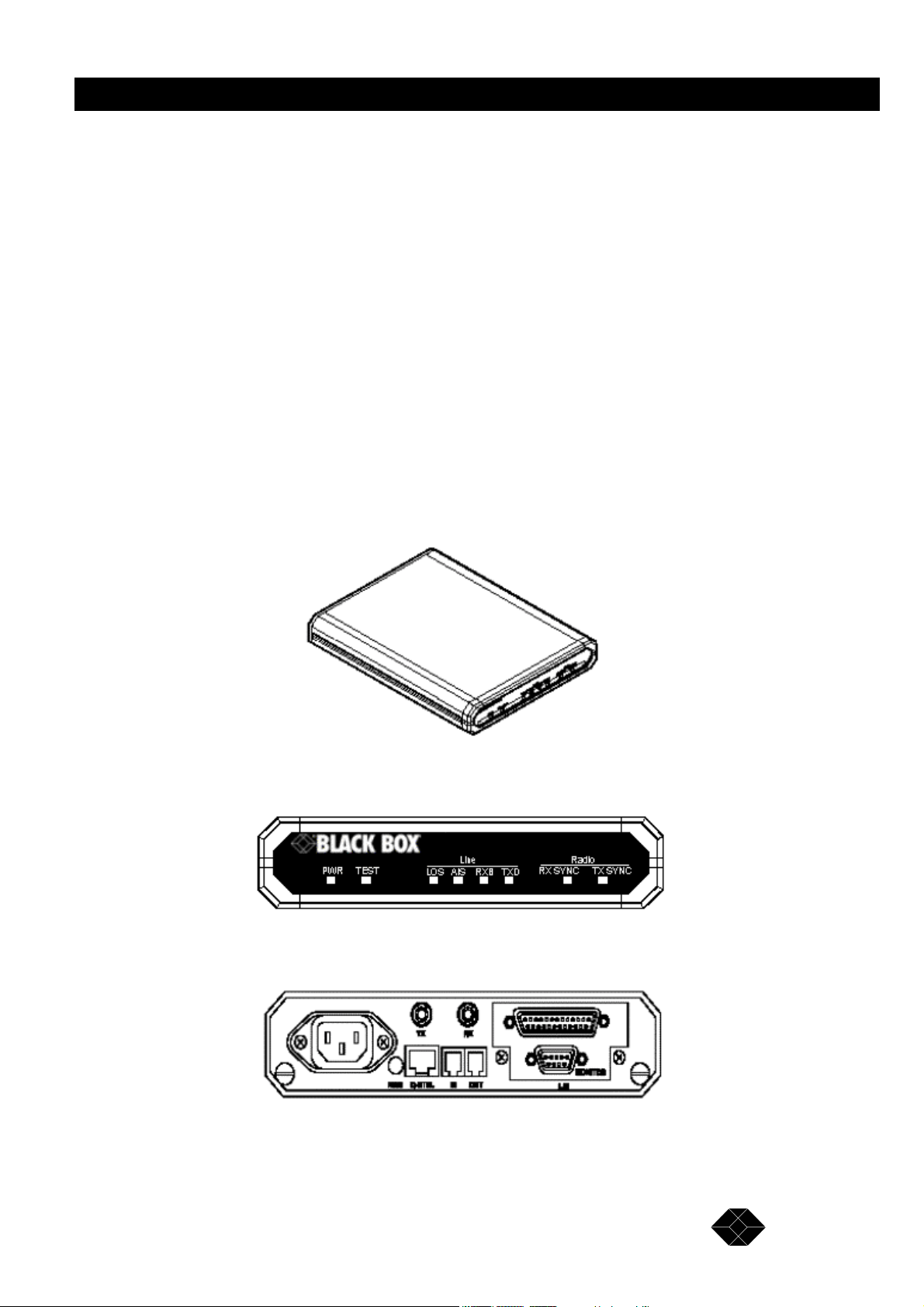
Figure 1.1: 2.048Mbps Wireless Modem
Figure 1.2: 2.048Mbps Wireless Modem Front Panel
Figure 1.3: 2.048Mbps Wireless Modem Rear Panel
TECHNICAL: 0118 931 2233
9
Page 10

2.048Mbps Wireless Modem
Main Features of the 2.048Mbps Wireless Modem
Wireless Connectivity
The 2.048Mbps Wireless Modem provides a wireless data link. The DSP modem with
adaptive equalization provides robust and reliable communication, overcoming problems
caused by fading or interfering signals.
Seamless Communication
A full-duplex system with independent transmitting and receiving modems and RF channels
allows seamless two-way communication.
Versatility
The 2.048Mbps Wireless Modem can transfer any kind of data, voice or video transmissions
and can be operated together with most types of bridges, routers and multiplexers. The
system supports the E1/T1 communication standards and with the appropriate Line Interface
Unit, is compatible with any other communication link standards and operates transparently
to data protocols. Fractional E1/T1 applications with voice channels are supported by a
special line interface unit, incorporating a built-in echo canceller for improved voice quality.
Error-Free Data Transfer
Spread Spectrum Frequency Hopping gives reliable low BER (Bit Error Rate) data transfer
and protection against interference. Error correction is provided by ARQ (Automatic
Retransmission Queuing).
High Speed Communication
High data rates enable fast, time saving communication. The 2.048Mbps Wireless Modem
supports full E1 rate of 2048 Kbps, full T1 rate of 1544 Kbps and transparent synchronous
speeds of n x 64 Kbps.
Easy Control and Monitoring
Eight LED indicators are provided for system status monitoring. Simple, easy to use
management menus provide configuration and diagnostics for both the local and remote unit
via an RS-232/V.24 connection. For further information on LED indicators see page15.
Remote Management
2.048Mbps Wireless Modem enables management of each unit from the other unit through
the Radio link.
10
SALES: 0118 965 5100
Page 11

2.048Mbps Wireless Modem
RSSI
Antenna reception can be fine-tuned by checking the strength of the received signal. To
check signal strength, connect a Digital Voltmeter (DVM) to the Receive Signal Strength
Indicator (RSSI) test point on the rear panel of the2.048Mbps Wireless Modem.
Co-location
This option enables to simultaneously establish a number of co-located links in star or
parallel topology, when they are synchronized in frequency via a synchronizing cable. Using
this option may be restricted by regulation in certain countries.
Choice of Antennas, Cables and RF Accessories
Several optional types of antennas, cables and RF accessories are provided allowing selection
of the RF components best suited for different applications.
2.048Mbps Wireless Modem Benefits
• Provides a cost-effective alternative to leased telephone cable service.
• Saves the expense of costly wire or fibre optic cable installation.
• Connects off-shore installations and sites separated by water, hazardous terrain or difficult
weather conditions.
• Is simple to install, giving immediate communication ability to remote sites.
• Links headquarters with branch offices.
• Provides a back-up link for cable connections.
2.048Mbps Wireless Modem Components
The 2.048Mbps Wireless Modem is comprised of four main components:
• Line Interface Unit
• Modem
• Radio
• Antennas
These components are described in detail in the following sections.
TECHNICAL: 0118 931 2233
11
Page 12
2.048Mbps Wireless Modem
Line Interface Unit
The Line Interface Unit connects the 2.048Mbps Wireless Modem to the WAN or to the DTE
(Data terminal Equipment). Any data, voice or video system can be connected to the
2.048Mbps Wireless Modem using standard interfaces:
• T1 DSX-1 - Line code B8ZS or Bipolar AMI
• E1 G703 - Line code HDB3 or Bipolar AMI
• Fractional T1 DSX-1 – Line code B8ZS or Bipolar AMI
• Fractional E1 G703 – Line code HDB3 or Bipolar AMI
• RS-530 digital interface. This interface also supports X.21 using an additional adapter
cable.
• V.35 digital interface.
The Line Interface Unit consists of an internal Network Interface Card and the applicable
connectors mounted on the rear panel of the unit. The 2.048Mbps Wireless Modem can be
ordered with the following optional Line Interfaces:
RS530
The rear panel connection is made with a D-Type, 25 pins female connector.
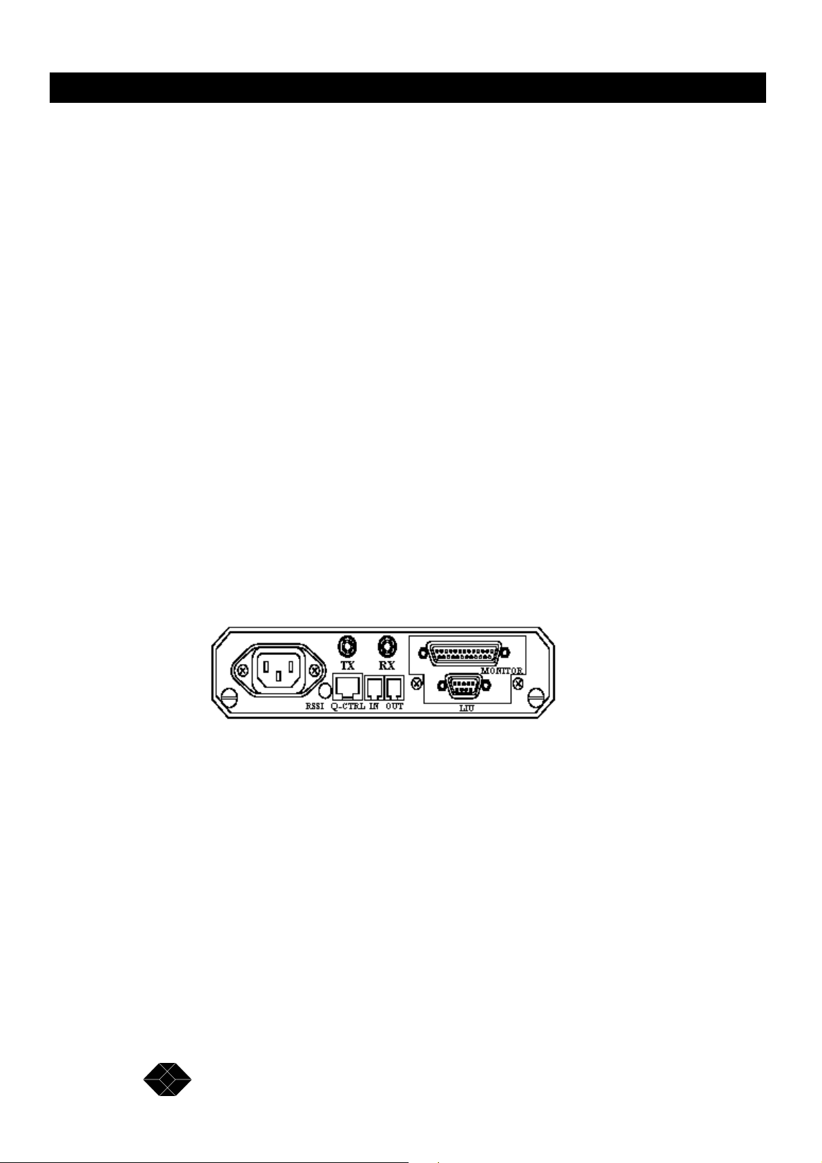
Figure 1-4. 2.048Mbps Wireless Modem Rear Panel (RS-530/X.21 LIU and V.35 LIU).
V.35
The rear panel connection is a D-Type, 25 pins female connector, the same as the RS-530
connector (see Figure 1-4). An additional cable plugs into this connector and comprises the
D-Type, 25 pins male connector on one end and a 34 pins female - “Winchester”- type V.35
connector on the other end.
X.21
The rear panel connection is a D-Type, 25 pins female connector, the same as the RS-530
connector (See Figure 1-4). An additional cable plugs into this connector and comprises the
D-Type, 25 pins male connector on one end and a D-Type, 15 pins female X.21 connector on
the other end.
12
SALES: 0118 965 5100
Page 13
2.048Mbps Wireless Modem
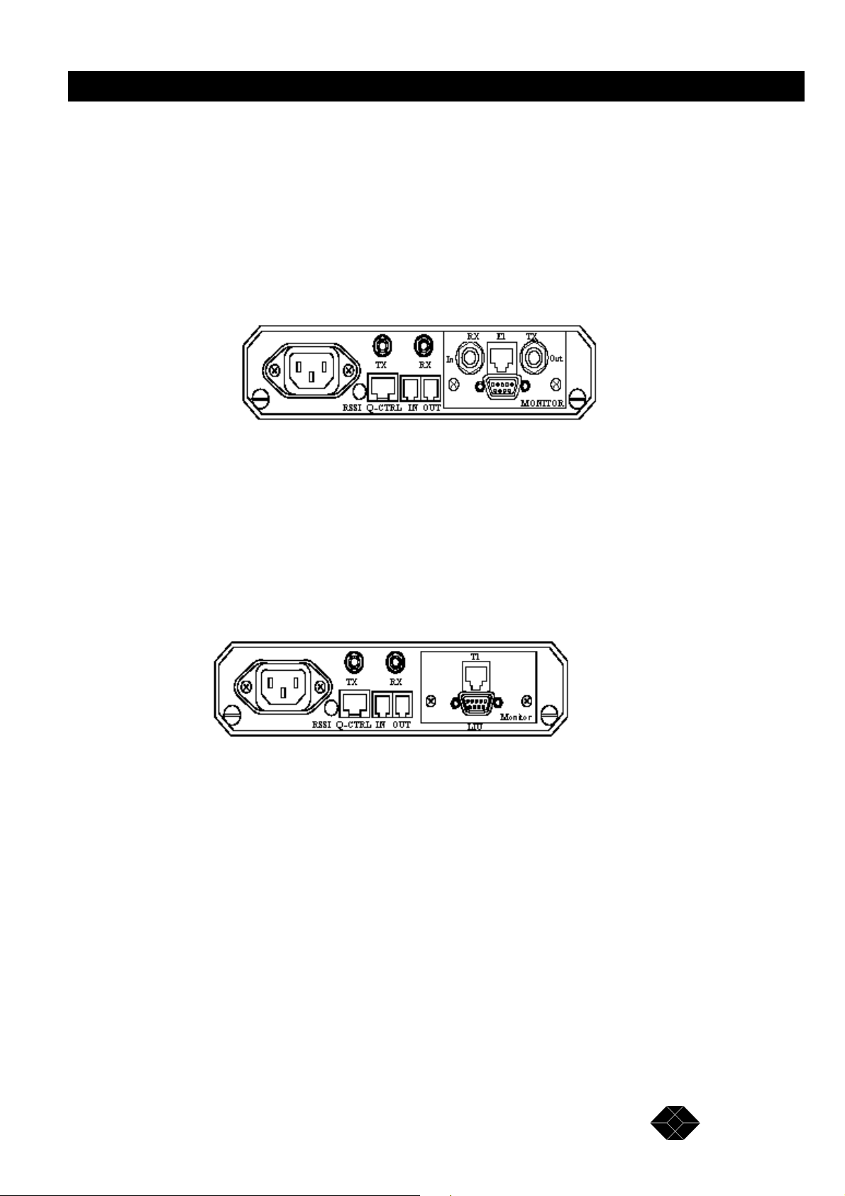
E1
The rear panel connector module consists of one E1/CEPT-1 balanced (RJ-45) connector and
two unbalanced (2 x BNC) connectors.
Fractional E1 (with Echo Cancellation)
The rear panel connector module consists of one E1/CEPT-1 balanced (RJ-45) connector and
two unbalanced (2 x BNC) connectors
Figure 1-5. 2.048Mbps Wireless Modem Rear Panel (E1 LIU and Fractional E1 LIU)
T1
The rear panel connector module consists of one T1/DSX-1 balanced (RJ-45) connector.
Fractional T1 (With Echo Cancellation)
The rear panel connector module consists of one T1/DSX-1 balanced (RJ-45) connector.
Figure 1-6. 2.048Mbps Wireless Modem Rear Panel (T1 LIU and Fractional T1 LIU)
Refer to Appendix E for a description of the E1/T1 and Fractional E1/T1 pin assignments.
Modem
Separate DSP Transmit and Receive Modems
The physical layer connection is established by two DSP (Digital Signal Processing)
modems. Each modem is dedicated to one direction of the link; transmit or receive.
Adaptive Equalization
The time dispersion of the transmitted signal caused by multipath propagation causes intersymbol interference (ISI). To compensate for the ISI, an adaptive equalizer is included in the
modem.
13
TECHNICAL: 0118 931 2233
Page 14

2.048Mbps Wireless Modem
ARQ – Based Error Correction
The 2.048Mbps Wireless Modem uses an Automatic Retransmission Queuing (ARQ)
mechanism to detect errors in received data and to request retransmission. The use of ARQ
results in a significant improvement in performance, overcoming problems caused by
interfering signals.
Radio
Full Duplex
The radio uses full duplex communication, transmitting and receiving simultaneously.
Spread spectrum Frequency Hopping
Using Spread Spectrum Frequency Hopping, a technique that changes the frequency of the
carrier over a hundred times per second, the radio “hops” in a pre-defined sequence through
up to 79 channels in the 2.4 - 2.5 GHz band. The number of channels and the frequency band
are determined by the specific model and relevant local regulations.
Frequency hopping provides reliable communication at low bit error rates as well as
increased bandwidth and interference avoidance.
Output Power
Radio power output is 16dBm (min.) at antenna port. Power emitted from antenna is up to
36dBm EIRP - US version, or 20 dBm EIRP – European version. In Low power mode, power
output is 2dBm.
Antennas
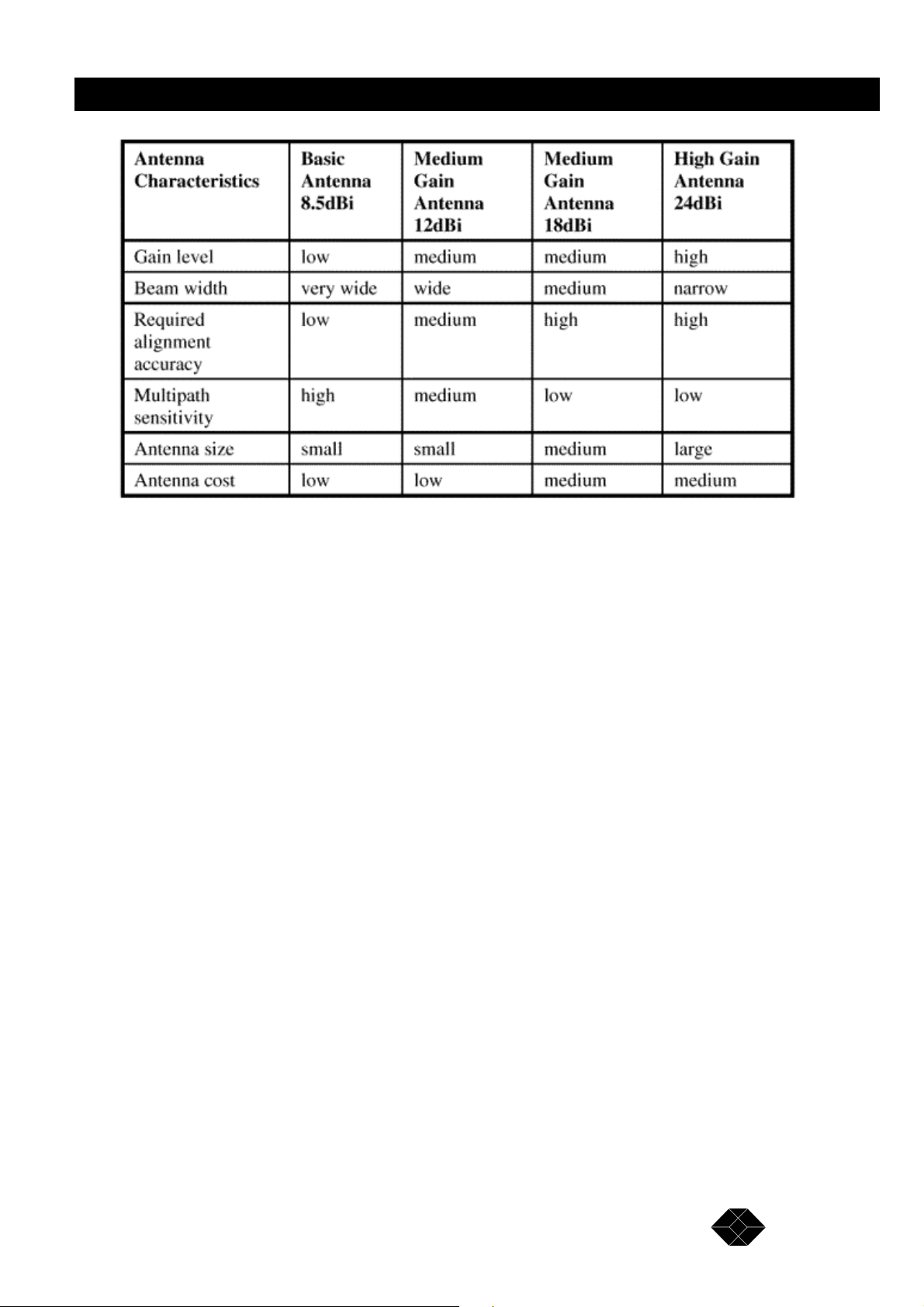
There is a variety of standard antennas and cable types for different gain levels.
Antenna Types
• Basic antenna - antenna gain of 8.5dBi.
• Medium gain antennas - antenna gain is either 12dBi or 18dBi.
• High gain antenna - antenna gain is 24dBi.
Cable Types
• Thin cable - this cable is thin and flexible, but its attenuation is relatively high.
• Thick cable - this cable is heavier and less flexible; its attenuation is lower.
• Low loss cable - this cable is thicker, heavier and more expensive, but its attenuation is very low.
14
SALES: 0118 965 5100
Page 15
2.048Mbps Wireless Modem
For further information on antennas, cables and related accessories see Chapter 2,
Installation, antennas and Accessories.
Antenna Interface
Antenna interface to the 2.048Mbps Wireless Modem is via two SMA connectors on the rear
panel; Transmit antenna should be connected to TX and Receive antenna to RX.
Front Panel Indicators
The front panel of the 2.048Mbps Wireless Modem contains eight LED indicators for
monitoring general functionality, DTE line functionality and radio functionality.
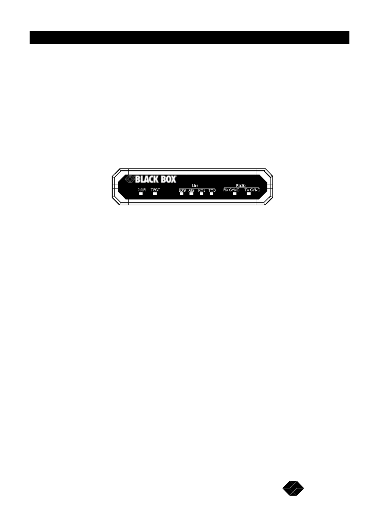
Figure 1-7. 2.048Mbps Wireless Modem Front Panel.,
General
PWR (On/Off)
Green lamp lights when power supply is connected. If lamp fails to light, check the power
cable and connectors.
Test
System self-test. Green LED should light all the time after power supply is connected. If LED
fails to light, disconnect from power supply, wait a few moments and try again. If self-test
fails repeatedly, contact Black Box technical support. The TEST LED will blink upon
identification of any alarm condition. Refer to pages 77-82 for more information on alarm
conditions.
Line
(Loss Of Signal - E1/T1 and Fractional E1/T1 only). Red LED lights when the modem loses
line signal from WAN or DTE. The main reason for loss of signal is a physical cable
problem.
1. Check the cables and connectors linking the unit with the WAN or the DTE.
2. If these are OK, check WAN or DTE functionality..,
TECHNICAL: 0118 931 2233
15
Page 16

2.048Mbps Wireless Modem
AIS
(Alarm Indication Signal - E1/T1 and Fractional E1/T1 only). Red LED lights when WAN or
DTE control frame is received by the modem indicating that information that should be sent
by the modem is not received by the DTE (or the WAN). The main reason for alarm
indication signal is a physical cable problem.
1. Check the cables and connectors linking the unit with the WAN or the DTE.
2. If these are OK, check WAN or DTE functionality.
RXD and TXD
Orange RXD and TXD LEDs indicate that data present at the LIU connector is sent over the
RF link to the remote LIU connector (this does not indicate that end equipment exists or is
synchronized).
Radio
Rx Sync
Green LED lights indicating radio receiving link active.
TX Sync
Green LED lights indicating radio transmission link active.
After power-on of the 2.048Mbps Wireless Modem configured as Master, the unit
immediately starts transmitting. At this stage, the TX Sync LED on the Master is on while the
RX Sync LED is off.
After power-on of the 2.048Mbps Wireless Modem configured as Slave, the unit starts to
search for a transmitting Master. At this stage both RX Sync and TX Sync LEDs on the Slave
are off.
After the Slave synchronizes with a transmitting Master, it immediately starts transmitting.
Now, both RX Sync and TX Sync LEDs on the Slave are on..
The RX Sync LED on the Master is on after reception from the transmitting Slave is
established. Failure of radio link reception or transmission may indicate one of the following:
• A problem in the radio configuration parameters (network ID, for example).
• A problem in the radio path (obstacles, for example).
• Antennas need adjustment.
16
SALES: 0118 965 5100
Page 17
2.048Mbps Wireless Modem
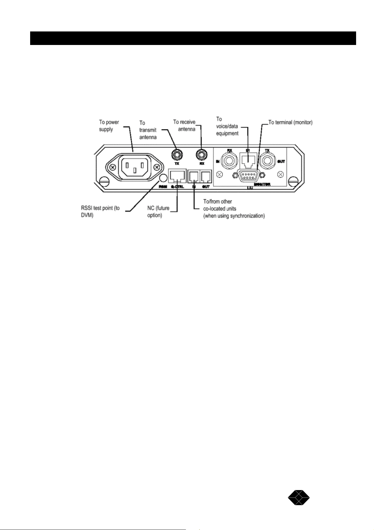
2.048Mbps Wireless Modem Connectors
Figure 1-8 shows how to connect the 2.048Mbps Wireless Modem to its antennas, the power
supply and to external equipment.
Figure 1-8. 2.048Mbps Wireless Modem Connections (E1 or Fractional E1 LIU)
TECHNICAL: 0118 931 2233
17
Page 18

2.048Mbps Wireless Modem
Installation Antennas and Accessories
Package Components
The 2.048Mbps Wireless Modem is shipped from factory with the following components:
• The 2.048Mbps Wireless Modem
• Power cord (110/220 VAC models), AC connector not supplied
• Monitor cable
• Synchronization cable (for collocated units)
• Cable adapter for DTE (V.35 and X.21 only)
• This user’s guide
Installing the 2.048Mbps Wireless Modem
General
The following steps provide a guide to the correct installation and configuration of the unit:
1. The 2.048Mbps Wireless Modem should be located indoors and positioned as close as
possible to the antennas.
2. Connect the unit to the end equipment. If the data interface on the DTE is either V.35 or
X.21, a cable adapter should be used as follows:
V35 25 pin D-Type connector to modem’s 34 pin V35 to DTE
X21 25 pin D-Type connector to modem’s 15 pin D-Type connector to DTE
3. Connect the antennas as follows:
• Connect the receive antenna to RX connector
• Connect the transmit antenna to the TX connector.
4. Connect the 2.048Mbps Wireless Modem to the power Outlet.
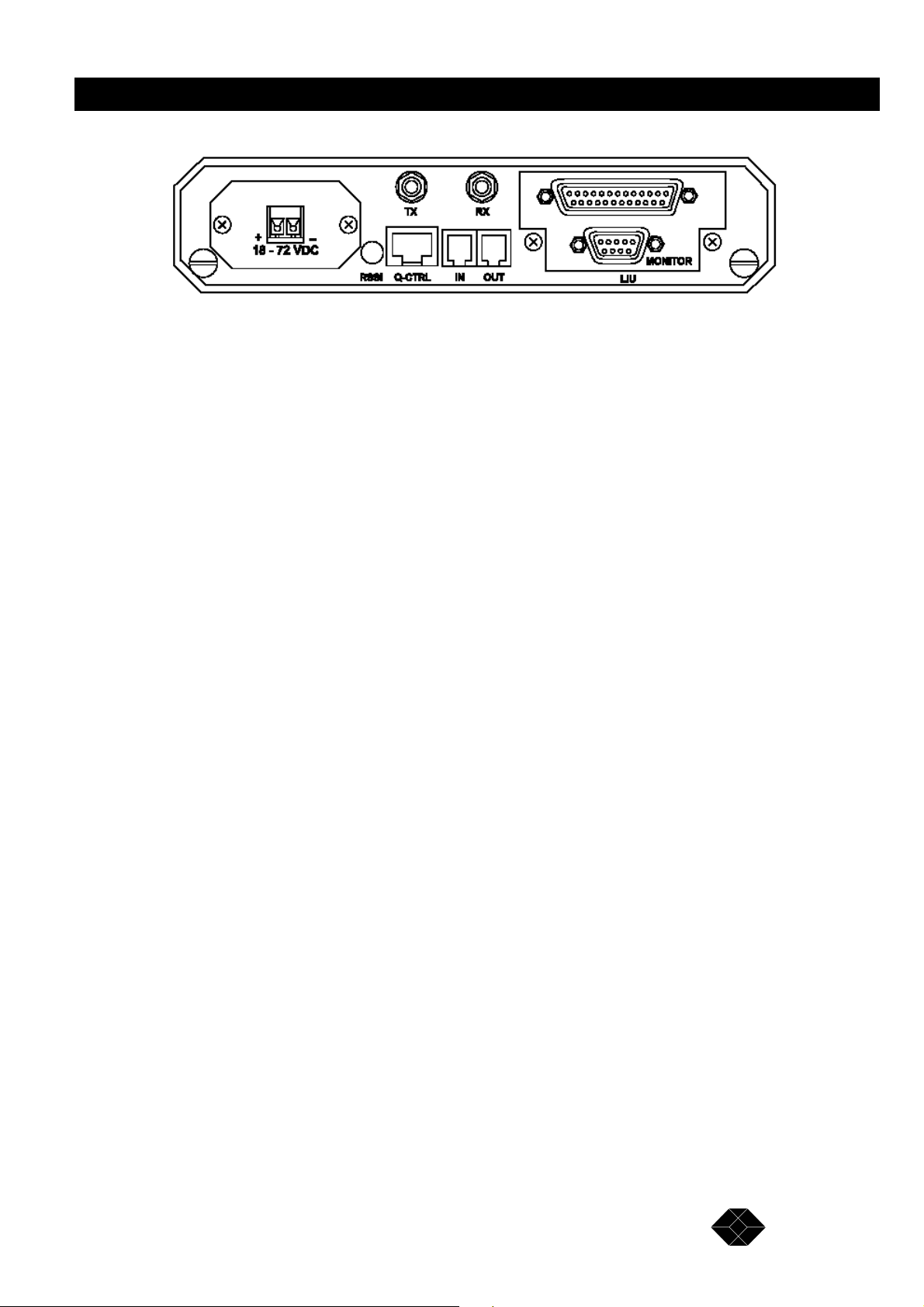
5. If you are using the 48 VDC model, open the two screws on the rear panel and slide out the
board a few centimetres to allow easy access to the terminal block. Verify that the wires are
securely connected and in the correct polarity according to Figure 2-1.
18
SALES: 0118 965 5100
Page 19
2.048Mbps Wireless Modem
Figure 2-1. 2.048Mbps Wireless Modem Rear Panel Showing 48 VDC Connector
6. For two 2.048Mbps Wireless Modems to communicate with one another, one side of the
link must be configured in Master mode, with the unit at the other side of the link configured
in Slave mode. Units are shipped from factory with a default setting of Slave. In an E1 or
T1 configuration, the Master modem must be located on the same side as the E1 or T1 master
(of the external equipment that provides the system clock).
Other basic parameters that should be configured for a quick start are:
• The clock rate (V3.5/RS-530/X.21 only). Both units must use the same clock rate.
• Select channels (Fractional E1/T1 only). Both units must use the same channels.
• Select channels with echo cancellation (Fractional E1/T1 with voice channels only).
Both units must be configured to use echo cancellation in the same channels.
To Configure the Unit as Master
1. From the Main menu, select 1 to access the Parameters menu.
2. From the Parameters menu, type 2 to select the MCP Parameters menu.
3. From the MCP Parameters menu. type 2. The Master-slave sub-menu opens.
4. Select the required configuration as follows:
• Type 0 for master
• Both units must be configured to operate at the same required clock rate. For
E1 and T1 the rate is set in factory.
To Set the Clock Rate (V.35/RS-530/X.21 only)
1. From the Main menu, select 1 to access the Parameters menu.
2. From the Parameters menu, type 1 to select the LIU (Line Interface Unit) Parameters menu.
3. From the LIU Parameters menu, type 5. The V.35/RS-530/X.21 sub-menu opens.
TECHNICAL: 0118 931 2233
19
Page 20

2.048Mbps Wireless Modem
4. From the V.35/RS-530/X.21 Parameters menu, type 1. The Clock Rate sub-menu opens.
5. Select the required clock rate according the required data rate of n x 64kb/S. For example:
• Type 1 for 64 Kbps
• Type 8 for 512 Kbps (8 x 64)
• Type 32 for 2048 Kbps (32 x 64)
Model BL512 allows data rates up to 512 Kbps only.
To Configure Channels - Fractional E1
1. From the Main menu, select 1 to access the Parameters menu.
2. From the Parameters menu, type 1 to select the LIU Parameters menu.
3. From the LIU Parameters menu, type 2 to select the Fractional E1 Parameters menu.
4. From the Fractional E1 Parameters menu, type 1 to select the Add/Remove channels menu.
5. From the Add/Remove Channels menu, type 1 to select the Add Channels menu.
6. View the current active channels. If channels that should be used are not included, enter
the numbers of the channels that should be added. Enter numbers between 1 to 31 separated
by a comma. Use two dots to indicate a range. e.g. 1,8..11,14 means add channels 1, 8, 9, 10,
11 and 14.
7. From the Add/Remove Channels menu, type 2 to select the Remove Channels menu.
8. View the current active channels. If channels that should not be used are included, enter
the numbers of the channels that should be removed from the list. Enter numbers between 1
to 31 separated by a comma. Use two dots to indicate a range. e.g. 2,5..7 means remove
channels 2, 5, 6 and 7.
To Configure Channels with Echo Cancellation- Fractional E1
1. From the Fractional E1 Parameters menu, type 8 to select the Add/Remove Echo
Cancellation on voice channels menu.
2. From the Add/Remove Echo Cancellation on voice channels menu, type 1 to select the Set
(Add) Channels menu.
3. View the current list of channels with echo cancellation. If channels that should be used
with echo cancellation are not included, enter the numbers of the channels that should be
added. Enter numbers between 1 to 31 separated by a comma. Use two dots to indicate a
range. e.g. 1,8..11,14 means set echo cancellation to channels 1, 8, 9, 10, 11 and 14.
Note: In systems with Channel Associated Signalling (CAS), echo cancellation should not be
set on channel 16, which is used for signalling.
20
SALES: 0118 965 5100
Page 21

2.048Mbps Wireless Modem
4. From the Add/Remove Echo Cancellation on voice channels menu, type 2 to select the
Clear (Remove) Channels menu.
5. View the current list of channel with echo cancellation. If channels in which echo
cancellation should not be used are included, enter the numbers of the channels that should be
removed from the list. Enter numbers between 1 to 31 separated by a comma. Use two dots to
indicate a range. e.g. 2,5..7 means remove echo cancellation from channels 2, 5, 6 and 7.
6. In Fractional T1 applications, both units should be configured to use the same channels. In
applications with voice channels, both units should be configured to use echo cancellation in
the same channels.
To Configure Channels- Fractional T1
1. From the Main menu, select 1 to access the Parameters menu.
2. From the Parameters menu, type 1 to select the LIU Parameters menu.
3. From the LIU Parameters menu, type 4 to select the Fractional T1 Parameters menu.
4. From the Fractional T1 Parameters menu, type 1 to select the Add/Remove channels menu.
5. From the Add/Remove Channels menu, type 1 to select the Add Channels menu.
6. View the current active channels. If channels that should be used are not included, enter
the numbers of the channels that should be added. Enter numbers between 1 to 24 separated
by a comma. Use two dots to indicate a range. e.g. 1,8..11,14 means add channels 1, 8, 9, 10,
11 and 14.
7. From the Add/Remove Channels menu, type 2 to select the Remove Channels menu.
8. View the current active channels. If channels that should not be used are included, enter
the numbers of the channels that should be removed from the list. Enter numbers between 1
to 24 separated by a comma. Use two dots to indicate a range. e.g. 2,5..7 means remove
channels 2, 5, 6 and 7.
To Configure Channels with Echo Cancellation- Fractional T1
1. From the Fractional E1 Parameters menu, type 0 to select the Add/Remove Echo
Cancellation on voice channels menu.
2. From the Add/Remove Echo Cancellation on voice channels menu, type 1 to select the Set
(Add) Channels menu.
3. View the current list of channels with echo cancellation. If channels in which echo
cancellation should be used are not included, enter the numbers of the channels that should be
added. Enter numbers between 1 to 24 separated by a comma. Use two dots to indicate a
range. e.g. 1,8..11,14 means set echo cancellation to channels 1, 8, 9, 10, 11 and 14.
TECHNICAL: 0118 931 2233
21
Page 22

2.048Mbps Wireless Modem
4. From the Add/Remove Echo Cancellation on voice channels menu, type 2 to select the
Clear (Remove) Channels menu.
5. View the current list of channel with echo cancellation. If channels in which echo
cancellation should not be used are included, enter the numbers of the channels that should be
removed from the list. Enter numbers between 1 to 31 separated by a comma. Use two dots to
indicate a range. e.g. 2,5..7 means remove echo cancellation from channels 2, 5, 6 and 7.
6. Activate the new settings by selecting 4 from the Main Menu (System Reset) to reset the
unit after configuration. The system must be reset for the modified parameters to take effect.
7. Verify link functionality using the LED indicators (See page 15, for LEDs description).
8. Further configuration may be done using the setup and configuration functions, as
described in Chapter 3.
Note: A unit running software version 1.7 is not compatible and cannot be connected in a
link to a unit running software version 1.6 and earlier.
Antennas, Cables and Accessories
There is a variety of standard antennas, cable types, and RF accessories for different gain
levels available.
Antennas
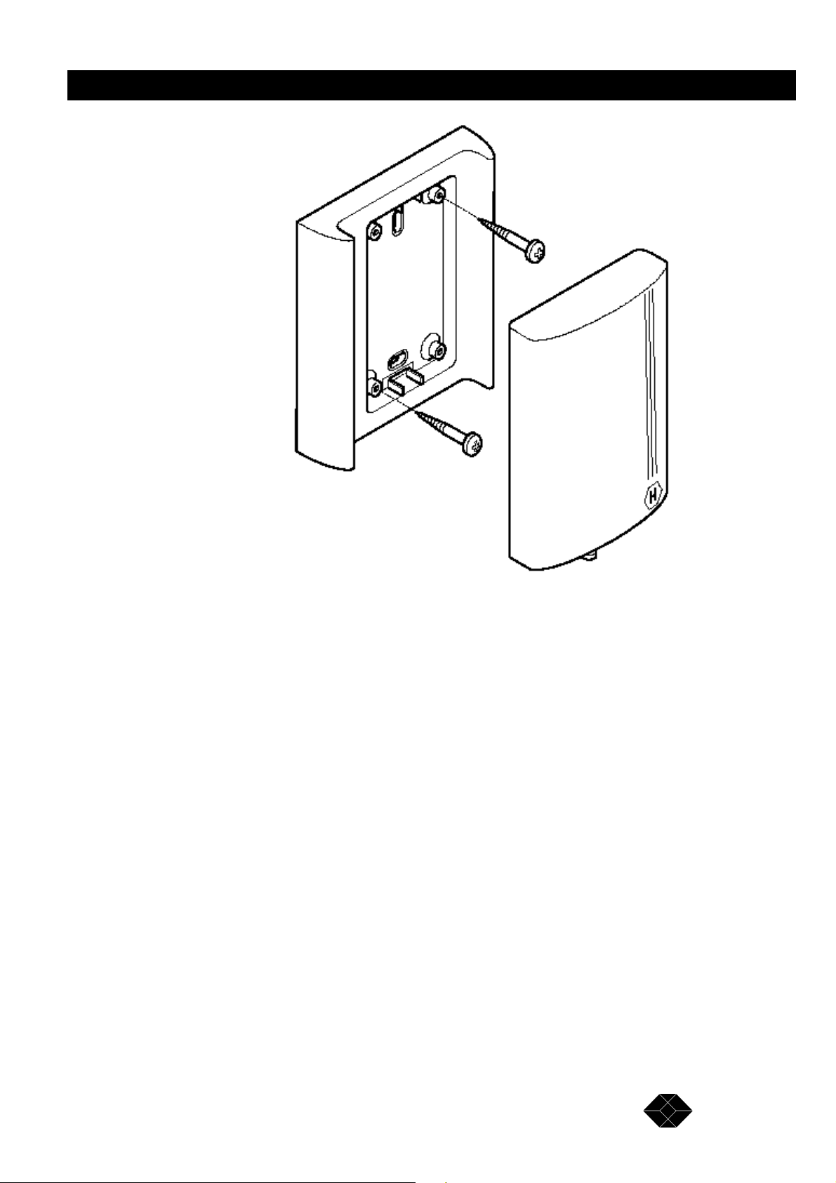
Basic Antenna (Uni-8.5)
The basic antenna has a gain of 8.5 dBi. Low alignment accuracy is required because of the
relatively large beam width (75 degrees horizontal, 50 degrees vertical ). It is intended for
indoor or outdoor installation in locations with relatively short distances between sites. UNI-
8.5 dimensions are: 101 x 95 x 32 mm. (4 x 3.75 x 1.25 in.).
22
SALES: 0118 965 5100
Page 23
2.048Mbps Wireless Modem
Figure 2-2. Basic 8.5 dBi Antenna Showing Installation screws.
Medium Gain 12dBi Antenna (Uni-12)
This medium gain antenna has a relatively wide beam width (22 degrees). It is intended for both
indoor and outdoor installations with medium distances between sites. UNI-12 Antenna dimensions
are: 15 x 15 x 38 cm. (6 x 6 x 15in.).
TECHNICAL: 0118 931 2233
23
Page 24

2.048Mbps Wireless Modem
Figure 2-3. Medium Gain 12dBi Antenna
Medium Gain 18dBi Antenna (Uni-18)
This medium gain antenna has a medium beamwidth (14 degrees) which increases the
sensitivity to inaccurate alignment, but decreases the influence of multipath propagation
(fading). It is intended for outdoor installations over medium to long distances. It is probably
the best choice for most medium to long range applications. UNI-18 Antenna dimensions are:
41 x 51 x 38 cm. (16 x 20 x 15 in.).
24
SALES: 0118 965 5100
Page 25

2.048Mbps Wireless Modem
Figure 2-4. Medium Gain 18dBi Antenna
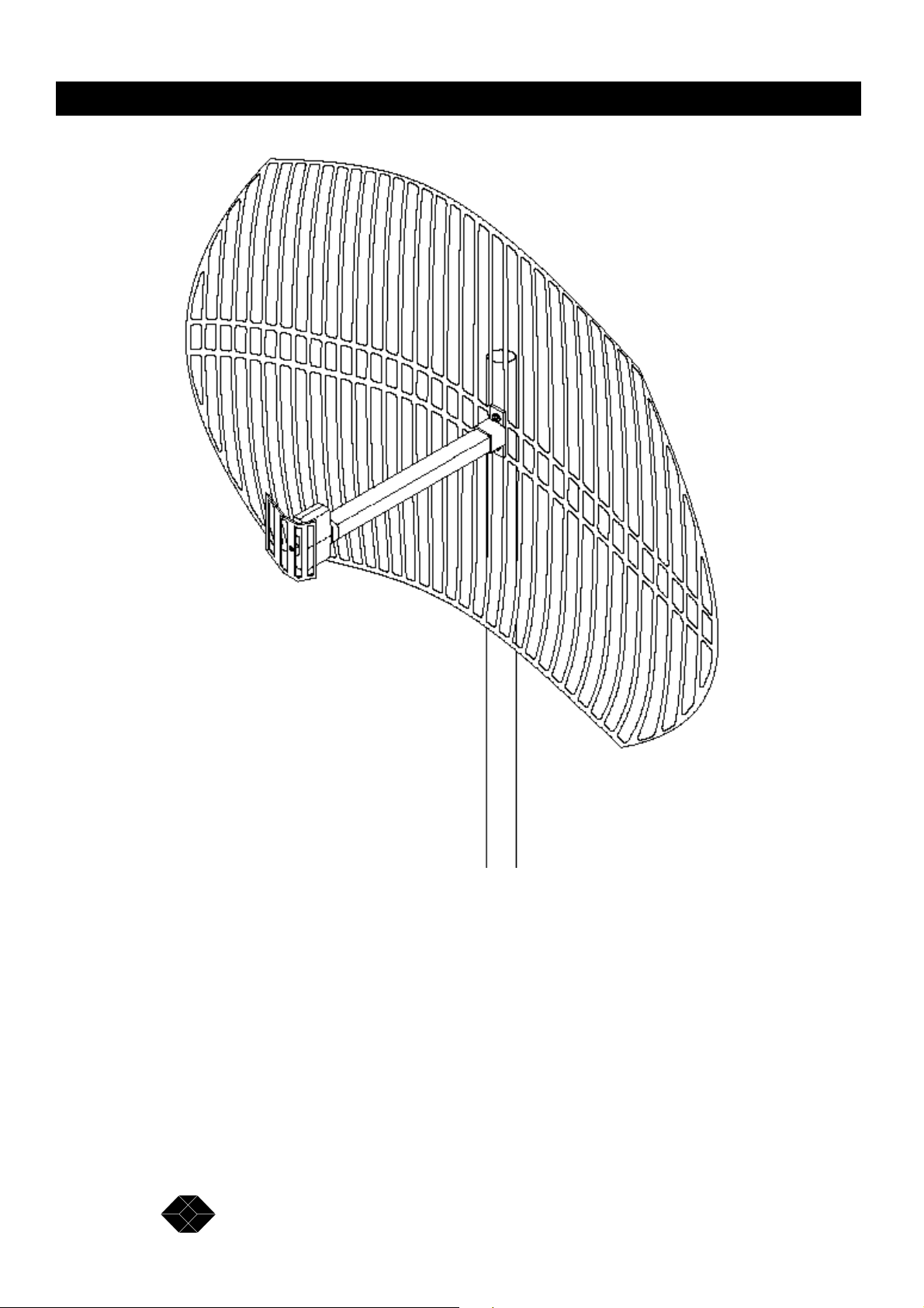
High Gain Antenna (Uni-24)
The gain of this antenna is 24dBi. It has a narrow beam width (7.5 degrees) which increases
the sensitivity to alignment inaccuracy but decreases the influence of multipath propagation
(fading). It is intended for outdoor installations for large distances. UNI-24 Antenna
dimensions are: 61 x 91 x 38cm. (24 x 36 x 15in.).
TECHNICAL: 0118 931 2233
25
Page 26
2.048Mbps Wireless Modem
Figure 2-5. High Gain 24dBi antenna.
Table 2-1 provides a summary of the main characteristics of the basic, medium and high gain
antennas:
26
SALES: 0118 965 5100
Page 27
2.048Mbps Wireless Modem
Table 2-1. Antenna Characteristics
RF Accessories
TPA 24 Transmit Power Amplifier
The TPA 24 amplifies the transmit power to a fixed output of 24 dBm (250 mW). The TPA
24 is especially useful when long RF cable runs are required. The TPA 24 also simplifies
antenna alignment by enabling the use of wider dispersion transmit antennas.
The TPA 24 comes in two models: TPA 24 LL and TPA 24 LH. The TPA 24 LL receives
input power in the range of -10dBm to 0dBm. The TPA 24 LH receives an input power of
0dBm to +10dBm. Both models then amplify the input power to a fixed output level of
24dBm (250mW). The TPA 24 gets its DC power supply from the modem transmitter
through the RF cable.
When used in compliance with ETSI regulations, the TPA 24 can be connected to cables and
antennas resulting in a total transmitted power of 20dBm (100 mW) EIRP.
See page 105 for further information.
TECHNICAL: 0118 931 2233
27
Page 28
2.048Mbps Wireless Modem
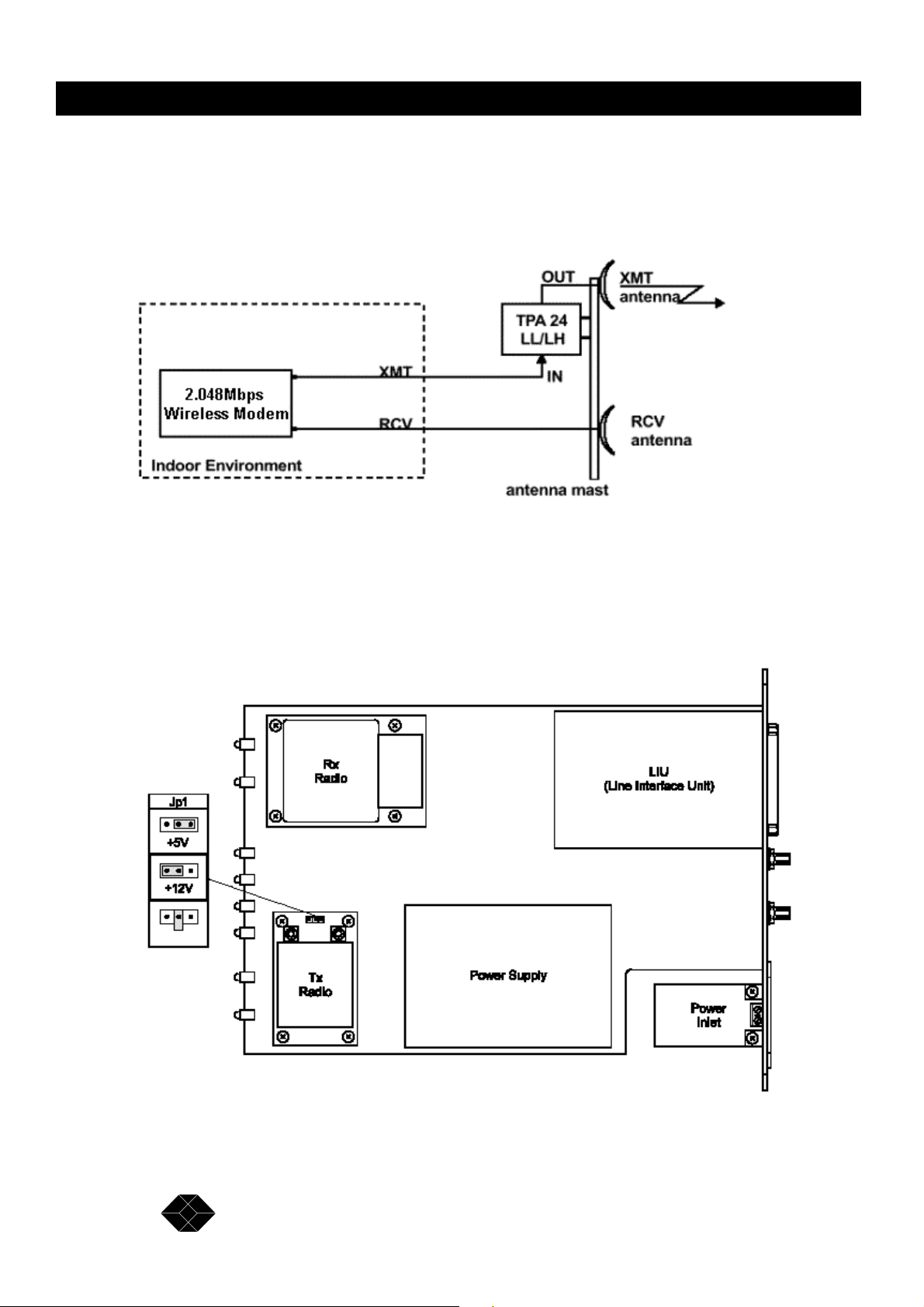
Installing the TPA 24
1. Install the TPA 24 as close as possible to the transmitting antenna.
Figure 2-6. TPA 24 Connections Diagram
2. Set the transmitter DC power supply of the 2.048Mbps Wireless Modem to 12V using the
internal jumpers according to Figure 2-15:
28
Figure 2-7. Jumper Setting for 12 VDC Power Supply Via the Transmit Radio
SALES: 0118 965 5100
Page 29
2.048Mbps Wireless Modem
Note: Installations exceeding regulations set by l ocal authorities expose the installer and the
user to potential legal and financial liabilities.
LNA-10 Low Noise Receive Amplifier
The LNA-10 is a high-performance, low-noise preamplifier designed to enhance fringe area
reception and to provide additional gain on the receive antenna, especially when using long
cable runs. The exceptionally small size and lightweight of the LNA-10 enables it to be
directly mounted on the antenna by means of the female RF IN connector. Power is obtained
through an RG-59 coaxial cable connected to the power supply. The LNA-10 incorporates
internal lightning and voltage surge protection.
See page 105 for further information.
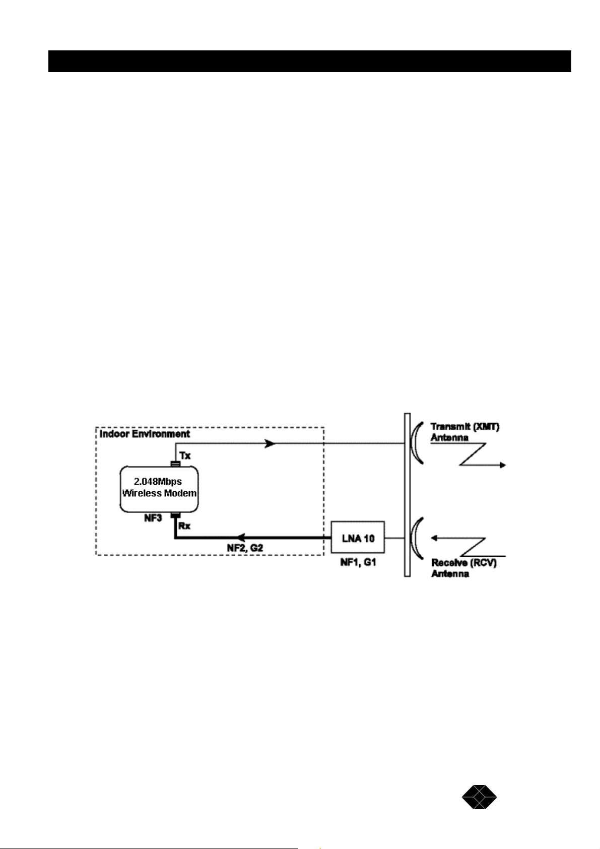
The LNA improves performance by improving the Noise Figure (NF) of the system, as
defined by the following formula:
LNA Improvement = NF (without LNA) / NF (with LNA) (*) Use this formula with absolute
values (not dB).
Consider the following typical configuration:
Figure 2-8. Achievable improvement through the use of LNA-10
To calculate the achievable improvement through the use of the LNA-10, use the following formulas:
NF (without LNA) = NF2 + (NF3 -1)/G2
NF (with LNA) = NF1 + (NF2 -1)/G1 + (NF3 -1)/(G1 *G2 )
Where:
NF1 = Noise Figure of LNA 10 = 1.4
29
TECHNICAL: 0118 931 2233
Page 30
2.048Mbps Wireless Modem
NF2 = Noise Figure of the cable = Loss of cable
NF3 = Noise Figure of the modem = 2.8
G1 = Gain of LNA 10 = 10
G2 = Gain of the cable = 1/Loss of cable
(*) All values above are taken in absolute value (not dB).
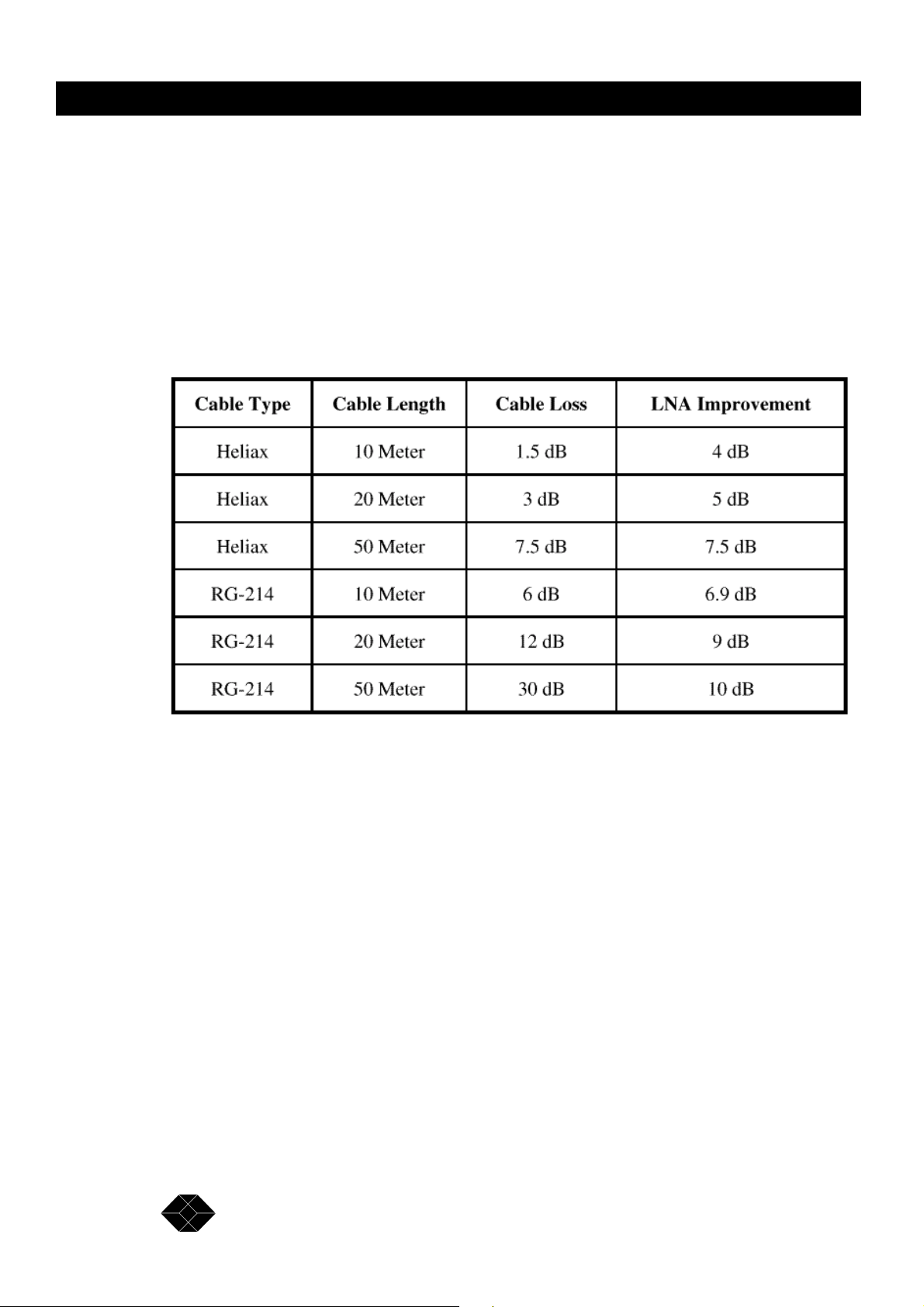
Use the following table to quickly determine the improvement of the LNA, given different
cable-loss. For convenience, the "LNA Improvement" value is converted to logarithmic
values (dB).
Table 2-2. LNA Improvement table
For example: in a typical installation with a 20 Meter Heliax cable, the use of an LNA-10
results in an improvement of 5dB to the total link margin, in comparison to the same
installation when not using the LNA-10.
1. Connect the LNA-10 RF input directly to the output of the receiving antenna.
2. Attach the LNA-10 RF output directly to the RF cable going down to the Rx connector on
the 2.048Mbps Wireless Modem unit.
3. Connect the RG-59 coaxial cable between the “TO CONV” connector of the power
inserter and the “Signal and Power out” connector on the LNA-10.
30
SALES: 0118 965 5100
Page 31

2.048Mbps Wireless Modem
Figure 2-9. LNA-10 Cable Connection Diagram
The power supply (PS) and Power Inserter are supplied with the LNA-10. The RG-59 coaxial
cable (with F-type connector) is not supplied and must be purchased separately.
Note: See Appendix C for installing other types of receive amplifiers
AL-1 Lightning Arrestor
The AL-1 Lightning Arrestor is used to protect transmitters and receivers from transients
originating from lightning or EMP. The AL-1 is gas tube-based and is not radioactive. The
gas discharge tube can sustain several transients if the time period between transients is
sufficient to allow the tube to cool down.
See page 106 for further information.
Installing the AL-1 Lightning Arrestor
1. Connect the antenna to the AL-1 input, as shown in Figure 2-15.
2. Connect the AL-1 ground connector to the building’s safety ground.
3. Connect the antenna from the AL-1 output to the antenna input in the modem.
TECHNICAL: 0118 931 2233
31
Page 32

2.048Mbps Wireless Modem
Figure 2-10. AL-1 Cable Connection Diagram
Cable Types
Thin Cable
This is a relatively thin and flexible cable. However, its attenuation is relatively high.
Impedance is 50W. Outer diameter is 5mm (0.195").
Thick Cable
This cable is thicker, heavier and less flexible than the thin cable. However, its attenuation is
less than that of the thin cable. Impedance is 50W. Outer diameter is 10.8mm (0.425").
Low Loss Cable
This cable is thicker, heavier and more expensive. However, its attenuation is very low.
Impedance is 50W. Outer diameter is 12.5mm (0.5"). The following table provides details on
the attenuation of standard cables available from Black Box.
32
Table 2-3. Attenuation of Standard Cables
SALES: 0118 965 5100
Page 33

2.048Mbps Wireless Modem
Professional Installers Only
Antennas, whether installed indoors or out, are to be installed ONLY by experienced antenna
installers that are familiar with local buildings and safety codes, and wherever necessary are
licensed by appropriate government regulators. Failure to do so may void the Product
Warranty and will certainly expose the end user to legal and financial liabilities. Black Box
are not liable for injury, damage or violation of government regulations associated with the
installation of antennas.
Antenna Sets
Black Box offers a variety of antennas, cables, RF accessories and installation accessories.
The following is a short list of sets available. Please consult technical support for more
details.
Examples of Black Box Antenna Sets
Figure 2-11. Wall Mount with Azimuth Alignment Only.
33
TECHNICAL: 0118 931 2233
Page 34

2.048Mbps Wireless Modem
Figure 2-12. Wall Mount with Azimuth and Elevation Alignment
34
Figure 2-13 One 12dBi Antenna
SALES: 0118 965 5100
Page 35

2.048Mbps Wireless Modem
Range Tables
Use the following tables to calculate the antennas and cables that will best suit your
transmit/receive range requirements (assuming line-of-sight between 2.048Mbps Wireless
Modem Master and Slave units). The tables are based on the assumption that the default
modem rate is being used. If a modem rate higher than the default rate is being used, the
achievable range should be estimated according to the actual modem rate.
Note: When selecting antennas, cables and RF accessories for your specific link, note that
exceeding the recommended power level of the input signal to the 2.048Mbps Wireless
Modem, may significantly reduce performance.
Maximal power level input into the Rx port should not exceed -10 dBm. For links with a radio
link rate of 3 Mbps, maximal power level input should not exceed -25 dBm.
Table 2-4. European Range Table
Table 2-5. USA Range Table
TECHNICAL: 0118 931 2233
35
Page 36

2.048Mbps Wireless Modem
Table 2-6. Maximum (Unregulated) Range Table
Antenna Alignment
In order to function properly and to provide quality results, the modems on either side of the
link must have a stable RF link. The alignment procedure is performed in three steps. First,
you visually align the antennas on both sides of the link. Next, you activate the Radio and
Line LEDs on the front panels of the units (which show basic synchronization) by a process
of adjusting the antennas. Finally, you fine-tune the adjustment of the antenna using the
RSSI (Received Signal Strength Indication) measurement procedure, described below.
For more information on pre-installation (Site Survey mode) and post-installation tests
(Counters and Tracers menu) see Chapter 3.
Step-1 Visually Aligning the antennas
1. Loosen the screws on the U-bolt that fasten the antenna to the mast (or the bolts on the wall
mount), and slowly move the antenna up and down (elevation) and from side-to-side
(azimuth), until the antenna points roughly in the direction of the site on the other side of the
link. For long distance links or when it is not possible to see the remote location, use a GPS
or a map and a compass for the first alignment.
2. Tighten the screws on the U-bolt (or the bolts on the wall mount).
Note: Repeat for each antenna - Rx and Tx on both units.
Step 2 –Activating the front panel LEDs
Two pairs of LEDs on the 2.048Mbps Wireless Modem front panel are lit when the units are
synchronized. When the Radio LEDs are both lit it is an indication that the radio link is
synchronized, and when the Line RXD and TXD LEDs are lit it is an indication that the line
to the DTE is synchronized.
36
SALES: 0118 965 5100
Page 37

2.048Mbps Wireless Modem
To activate the front panel LEDs:
1. If the LEDs are not lit, loosen the screws on the U-bolt that fasten the Rx and Tx antennas
to the last (or the bolts on the wall mount) and slowly move the antennas up and down
(elevation) and from side-to-side (azimuth), until all four LEDs are lit (Radio - RX Sync and
TX Sync, Line –RXD and TXD).
2. Tighten the screws on the U-bolt (or the bolts on the wall mount).
Step 3 – Fine tuning the adjustment of the antenna using RSSI Measurement
The RSSI (Receive Signal Strength Indicator) enables to fine-tune antenna alignment by
supplying a measured value of the signal received by the unit. Maximizing the RSSI value
optimises performance.
The RSSI value can be viewed using the local monitor, as described on page 72. The RSSI
per channel feature displays in graphic format the strength of the received signal on each of
the RF channels in use. The modem also enables to collect a measurement of the average
RSSI using a DVM (digital voltmeter) connected to the RSSI test pin in the rear panel of the
unit. The measured DC voltage is relative to the RSSI value as indicated in Figure 2-15. The
2.048Mbps Wireless Modem enables to perform RSSI measurement using a DVM also near
the Receive Antenna. This procedure simplifies the tuning process, by allowing easier
reading of the RSSI level while moving the antenna.
The RSSI measurement (with DVM or monitor) indicates the strength of reception. In order
to maximize the reception strength, the receive antenna and the transmit antenna on the
remote site of the link must be aligned facing each other until maximum signal quality is
obtained. This procedure should be repeated on the modems on both sides of the link.
Note: The RSSI measurement indicates the strength of received signal in the 2.4 -2.5 GHz
band. Verify that you are not aligning the antenna towards an undesired source of energy in
this band (See also page 82).
⇒ To fine-tune the antenna alignment using a DVM connected directly to the unit:
1. Connect one of the DVM probes to the RSSI test pin. Connect the other probe to the case
chassis.
Figure 2-14. RSSI measurement connection diagram
37
TECHNICAL: 0118 931 2233
Page 38

2.048Mbps Wireless Modem
2. Loosen the screws on the U-bolt that fasten the receive antenna to the mast (or the bolts on
the wall mount) and slowly move the antenna up and down (elevation) and from side-to-side
(azimuth) until you receive a maximum RSSI reading on the DVM. (See Figure 2-15).
3. Tighten the screws on the U-bolt (or the bolts on the wall mount).
Figure 2-15. RSSI test point accuracy.
⇒ To fine-tune the antenna alignment using a DVM near the receive antenna:
The modems can be configured send a DC signal through the RCV antenna connector. This
signal is proportional to the RSSI voltage, which is present at the RSSI output on the rear
panel.
1. Set a Bias-T connection before the Receive Antenna.
Figure 2-16. A Bias-T connection for RSSI measurement near the Receive Antenna
2. Set the jumpers in the Receive module of the 2.048Mbps Wireless Modem to the RSSI position.
38
SALES: 0118 965 5100
Page 39

2.048Mbps Wireless Modem
Figure 2-17. Jumper Setting for RSSI measurement via the Receive RF Cable
3. Connect a DVM to the DC port of the Bias-T.
4. Loosen the screws on the U-bolt that fasten the receive antenna to the mast (or the bolts on
the wall mount) and slowly move the antenna up and down (elevation) and from side-to-side
(azimuth), until you get a maximum RSSI reading on the DVM.
5. Tighten the screws on the U-bolt (or the bolts on the wall mount).
Note: If you remove the Bias-T connection after the fine-tuning process, you must set the
Jumpers in the Receive module back to the default position (NC ), otherwise the modem will
not function. In addition, damage might be caused to the modem if the Receive Antenna is
connected directly to the Receive cable, and the jumpers are not in the default position
TECHNICAL: 0118 931 2233
39
Page 40

2.048Mbps Wireless Modem
Figure 2-18. Default position (NC) of the Jumpers in the Receive Module.
Synchronizing Co-located Modem Units
When two or more 2.048Mbps Wireless Modem units are co-located, you should perform the
following procedures in order to allow optimal performance. These procedures enable
synchronization of the hopping sequences used by the links, and ensure sufficient separation
between frequencies used by the links at any given time.
40
SALES: 0118 965 5100
Page 41

2.048Mbps Wireless Modem
Figure 2-19. Several Co-located modems in a “star” configuration
Note: On the Master side, the 2.048Mbps Wireless Modem units with a SW version 1.6 and
up and HW version 2 must be used. On the Slave side, 2.048Mbps Wireless Modem units with
a SW version 1.6 and up can be used with either HW version 2 or previous HW version.
Step-1: Installing the Antennas
Install the antennas of the co-located units to minimize interference. The antennas of the
different units should be located as far from each other as possible, and no antenna should be
located in the radiating direction of any of the other antennas.
Step-2: Setting the relevant parameters
Set the Modem Rate, the Network I.D., the Master-Slave mode and the Number of Links to
synchronize according to these guidelines:
• Configure all units connected by the synchronization cable as “Master”. Configure the units
on the other side of the link as “Slave”.
• All units should have the same “Modem rate”, “Hopping standard”, “Hopping sequence”
and “Number of links to synchronize”. It is not possible to synchronize two 2.048Mbps
Wireless Modems that have different modem rates.
TECHNICAL: 0118 931 2233
41
Page 42

2.048Mbps Wireless Modem
• Set “Number of links to synchronize” to a value greater or equal to the actual number of
connected links. This setting is not necessary for the “Slave” units.
Note: Selecting the option “Synchronize as many links as possible” may result in less than
optimal performance. Use this option only in situations where co-located links are added
and/or deleted frequently.
• Use the following table to determine the maximum number of links to synchronize:
Table 2-7. Maximum Number Synchronized Links
• Set “Network I.D.” for the links consecutively from 1 up to the “Number of links to
synchronize” (assign a different Network I.D. for each link). Note: You can access the
above parameters through the Setup and Configuration Menu (in Chapter 3).
• If several links are established between two “centers”, define the units in one of the
centers as Master.
42
SALES: 0118 965 5100
Page 43

2.048Mbps Wireless Modem
Figure 2-20. Several Co-located 2.048Mbps Wireless Modems in a “center-to-center”
configuration.
Step-3 Connecting the Master units
Establishing synchronization is a “Hot Plug-In” process: You can add a new link without
interfering with the normal operation of the working link(s), provided the relevant parameters
are properly set (as described above).
Figure 2-21. Connecting Units for Synchronization
Use a standard FCC 68 4-pin plug (male) to FCC 68 4-pin plug (male) telephone cable with
two twisted pairs (supplied by Black Box) to interconnect the Master units that should be
synchronized.
Figure 2-22. Synchronization Cable
43
TECHNICAL: 0118 931 2233
Page 44

2.048Mbps Wireless Modem
Set-up and Configuration
Set-up and Configuration Functions
This section explains how to access and set the Set-up and Configuration functions that are
provided for the 2.048Mbps Wireless Modem. The main parameters to set are:
• Line interface unit set-up parameters
• Management control parameters
• Modem set-up parameters
• Radio set-up parameters
Accessing the Set-up and Configuration Functions
You can access the Set-up and Configuration functions by connecting a terminal to the
RS232/V.24 monitor interfaces on the rear panel of the 2.048Mbps Wireless Modem.
The local monitor allows you to access the set-up parameters from an ASCII ANSI terminal,
or from a PC running a terminal emulation program, such as the Windows Hyper Terminal or
Procomm. Use the following settings:
• Baud rate 9600
• Data bits 8
• Stop bits 1
• Parity None
• Flow control None
• Connector Available Com port
Connect the terminal to the monitor interface of the 2.048Mbps Wireless Modem. The
monitor appears displaying the main menu.
Main Menu
When the Setup and Configuration screen appears the main menu is displayed, providing
general status information and access to other menus:
44
SALES: 0118 965 5100
Page 45

2.048Mbps Wireless Modem
Figure 3-1. Main Menu
Note: Hardware version 2 includes all features of Hardware version 1, plus co-location
support through synchronization and RSSI test point.
Parameters Menu
This menu enables the authorized user to set the main system parameters:
• LIU parameters – setting Line Interface Unit Parameters
• MCP parameters – setting Management and Control Parameters
• Radio and Modem Parameters – setting Radio and Modem Parameters
• REMOTE parameters –viewing and/or setting parameters of the remote unit
• Load Default Values –loading the factory default values
• Parameters Info. Screen –viewing the status of main parameters
Counters and Tracers Menu
This menu enables you to view system statistics and alarms.
Mode and Access Control Menu
The Mode and Access Control menu enables to define the access rights. It also enables access
to the Site Survey Mode for surveying the applicable electromagnetic environment of the site
(this does not require a password).
TECHNICAL: 0118 931 2233
45
Page 46

2.048Mbps Wireless Modem
System Reset
Resetting the system from the System Reset menu implements all the changes made to the
parameters of all the Setup and Configuration functions.
Testing
This menu is for authorized Black Box technical staff only.
Parameters Menu
You can access most of the items for configuring your 2.048Mbps Wireless Modem from the
parameters Menu:
To access the Parameters Menu:
• In the Main menu, at the Select Option prompt, type 1.
The Parameters menu appears.
To make selections using the Parameters menu:
At the Select Option prompt, type the number that corresponds to the option you require:
• Type 1 to select the LIU Parameters menu.
•
• Type 2 to select the MCP Parameters menu.
•
• Type 3 to select the Modem and Radio Parameters menu.
•
• Type 4 to select the Remote Parameters menu.
•
• Type 5 to select the Load Default Values menu.
•
• Type 6 to select the Parameters Info. Screen.
1. Follow the instructions on the screen.
Parameters menu
===============
1 - LIU Parameters
2 - MCP Parameters
3 - RADIO and MODEM Parameters
4 - REMOTE Parameters
5 - Load Default Values
6 - Parameter Info. Screen
Figure 3-2. Parameters Menu
46
SALES: 0118 965 5100
Page 47

2.048Mbps Wireless Modem
2. Press Esc at any stage to return to the previous menu (if you press Esc before making any
selection, the message:
Loading cancelled, old value retained appears).
Note: You can operate all the Setup and Configuration sub-menus by using these procedures
and by following the instructions on the screens.
LIU Parameters Menu
The LIU Parameters menu gives you access to the following sub-menus:
• E1 Parameters Menu (select if an E1 LIU is used).
• Fractional E1 Parameters Menu (select if a Fractional E1 LIU is used).
• T1 Parameters Menu (select if an T1 LIU is used).
• Fractional T1 Parameters Menu (select if a Fractional T1 LIU is used).
• V.35/RS-530/X.21 Parameters Menu. (Select if a V.35/RS-530/X.21 LIUis used).
• Loopback Mode.
• Line Interface Unit type (set at factory and should not be changed unless LIU changes).
E1 Parameters Menu
Table 3-1. E1 Parameters Menu Items and Actions
47
TECHNICAL: 0118 931 2233
Page 48

2.048Mbps Wireless Modem
E1 Alarm Buffer
The Possible alarms are:
• LOS (all zeros signal): Loss Of Signal – No signal is received from the data equipment.
• AIS: Alarm Indication Signal – No signal is received by the connected end equipment.
When an alarm is detected, a note appears at the bottom of the display (Note: An alarm
has been activated), and the message ALARM EXISTS is displayed on the menu
header (see Figure 3-1). In addition, the TEST LED will blink.
Fractional EI Parameters Manu
See also Appendix C.
48
SALES: 0118 965 5100
Page 49

2.048Mbps Wireless Modem
Table 3-2. Fractional E1 parameters Menu Items and Actions
Remote Alarm Method
Two methods may be used to indicate to the end equipment of an alarm condition following
loss of synchronization:
• Bit 3 of TS (Time Slot) 0: Under normal conditions, this bit is always set to 0. Upon
identification of an alarm condition, it is set to 1.
• Unframed all ones: The transmitted signal comprises a continuous sequence of ones
without any ramming or other signalling messages The Remote alarm method should
be set in accordance with the configuration of the end equipment.
49
TECHNICAL: 0118 931 2233
Page 50

2.048Mbps Wireless Modem
Long haul/Short haul
This parameter determines the sensitivity of the receiver circuits in the line interface to the
end equipment. If the distance between modem and the end equipment is up to 500 meters, it
should be set to 0 (short haul). If the distance is more than 500 meters, it should be set to 1
(long haul) to compensate for losses by increasing the sensitivity of the receiver circuits by
approximately 30 dB.
CRC4 Usage
When there is a need for an enhanced error monitoring capability, bit 1 of each frame is used
for a Cyclic Redundancy Check 4 (CRC4) procedure. Bit 1 of each frame is used for CRC4
bits and other related information such as a CRC4 alignment sequence to verify identification
of the CRC4 bits. These bits are the result of a certain calculation performed on all the bits of
the applicable sub-multiframe (8 frames). CRC4 bits may be used by the receiving equipment
to determine proper reception of all bits sent to it. If the end equipment does not use CRC4,
these bits may be used for other purposes, and the CRC4 Usage parameter should be set to 0
(CRC4 not used). If the end equipment uses CRC4, or if it is not known whether the end
equipment uses CRC4, this parameter should be set to 1 (Auto detect CRC4).
Echo Canceller disabling method
Set these parameters in accordance with the echo cancellation disabling method used by the
end equipment (see also appendix C).
• Straight 2100Hz tone (0): The most popular method based on transmitting a straight
2100Hz tone.
• Phase reversed 2100Hz tone (1): A 2100Hz tone with phase reversals for improved
differentiation from voice signals.
• 2100Hz VPA tone (2): A tone in the range 2000-2100Hz.
Fractional E1 Alarm Buffer
LOS (Loss Of Signal) Also referred to as all zeros signal, indicates that no signal is received
from the data equipment.
AIS (Alarm Indication Signal) No signal is received by the connected end equipment.
Remote Frame Alarm Indication from the connected end equipment that it is not able to
synchronize with the modem.
Frame-slip Indicates lack of compatibility between the clocks of the modem and the end
equipment.
50
SALES: 0118 965 5100
Page 51

2.048Mbps Wireless Modem
Remote-BreezeLINK-Unsync Indicates a temporary incidence of a very noisy radio
channel. Repeated occurrences indicate either a very noisy radio channel or a hardware
problem (e.g. clocks with excessive jitter) or a problem related to configuration of clocks.
Too many BPV/CV Too many Bipolar code violations, indicates selection of Bipolar AMI
line code in the modem when the end equipment uses HDB3 line code.
When an alarm is detected a note appears at the bottom of the display: (Note:An alarm
has been activated), and the message ALARM EXISTS is displayed on the menu
header (see Figure 3-1). In addition, the TEST LED blinks.
T1 Parameters Menu
Table 3-3. T1 Parameters Menu Items and Actions
Pulse Shape
The current selection is displayed (the “NOT DEFINED” message is displayed if LIU used is
not T1). The selection should be made according to the length of the line connecting the
terminal equipment to the 2.048Mbps Wireless Modem, and according to the type of
application (CSU or DSU network interface). The selection affects the pulse mask used in the
interface according to the requirement specified in the applicable standard (DSX-1 for DSU
network interface, ANSI T1.403 for CSU network interface). See Appendix B for more
details about CSU and DSU network interfaces.
T1 Alarm Buffer
The possible alarms are:
• LOS (all zeros signal): Loss Of Signal – No signal is received from the data equipment.
• AIS: Alarm Indication Signal – Signal is not received by the data equipment.
TECHNICAL: 0118 931 2233
51
Page 52

2.048Mbps Wireless Modem
When an alarm is detected, a note appears at the bottom of the display (Note: An alarm
has been activated) and the message: ALARM EXISTS is displayed on the menu
header (see Figure 3-1). In addition, the TEST LED will blink.
Fractional T1 Parameters Menu
See also Appendix C.
52
SALES: 0118 965 5100
Page 53

2.048Mbps Wireless Modem
TECHNICAL: 0118 931 2233
53
Page 54

2.048Mbps Wireless Modem
54
SALES: 0118 965 5100
Page 55

2.048Mbps Wireless Modem
Superframe Method
Each frame transmitted to (or received from) the end equipment is comprised of 193 bits,
numbered 1 to 193. Bit numbers 2 to 193 are used for data. The first bit of each frame is
designated an F-bit, and is used for purposes such as frame alignment, performance
monitoring (CRC check) and providing a data link. There are two alternative methods for
allocation of F-bits:
• ESF: A 24-frame multiframe. F-bits provide frame alignment signal (FAS), a 4Kbps
data link with the connected equipment (DL), and CRC-6 block check field.
• D4: A 12-frame multiframe. F-bits provide frame and multiframe alignment signal (No
CRC or data link). Set this parameter to 0 (D4) or 1 (ESF) in accordance with the
connected end equipment.
D4 Yellow Alarm Method
Yellow alarm is an indication, using the D4 multiframe method, that the sending equipment is
unsuccessful in synchronizing with the receiving equipment. There are two methods of
transmitting the yellow alarm message:
• D4 bit 2 mode: Setting bit number 2 of all channels to 1
• D4 F-bit mode: Setting a specific F-bit to 1
Set the D4 yellow alarm method to 0 (bit 2 mode) or 1 (F-bit mode) in accordance with the
configuration of the connected end equipment
Pulse Shape
The current selection is displayed (the NOT DEFINED message is displayed if LIU used is
not T1). The selection should be made according to the length of the line connecting the
terminal equipment to the 2.048Mbps Wireless Modem, and according to the type of
application (CSU or DSU network interface). The selection affects the pulse mask used in the
.
TECHNICAL: 0118 931 2233
55
Page 56

2.048Mbps Wireless Modem
interface, as per the requirement specified in the applicable standard (DSX-1 for DSU
network interface, ANSI T1.403 for CSU network interface). See Appendix C for more
details about CSU and DSU network interfaces.
CRC6 Usage
The F-bits in an ESF multiframe (see Superframe method above) provide Cyclic Redundancy
Check 6 (CRC6) information. These bits are the result of a certain calculation performed on
all the bits of the previous multiframe (24 frames). CRC6 bits may be used by the receiving
equipment to determine correct reception of all bits sent to it. There are two common CRC6
procedures:
• In accordance with the ANSI, AT&T and ITU-T standards
• In accordance with the Japanese JT-704 standard.
Set CRC Usage in accordance with the CRC6 procedure used by the connected end
equipment.
Bit 7 Zero Suppression
When using AMI line code, the occurrence of too many successive zeros should be avoided
to ensure accurate reconstruction of the data. Some devices use a method known as zero
suppression. This method forces bit 7 of each 8-bit channel to 1 if all the bits in the original
channel are zero.If the connected end equipment uses the bit 7 zero suppression method, this
parameter should be set to 1 (Force bit 7 zero suppression). Otherwise (see also Pulse Density
Enforcer below) it should be set to 0 (no suppression). If the line code used is B8ZS, it must
be set to 0 (no suppression). When transmitting data (non-voice) it must be set to 0 (no
suppression) unless the data is preconditioned not to send “all zero” bytes.
Pulse Density Enforcer
When using AMI line code, the occurrence of too many successive zeros should be avoided
to ensure accurate reconstruction of the data. Some devices use a method known as Pulse
Density Enforcer according to ANSI T1.403. This method checks the number of ones, and
upon detecting too many successive zeros it forces certain bit(s) to one. If the connected end
equipment uses the Pulse Density Enforcer method, this parameter should be set to 1 (Enable
Pulse Density Enforcer). Otherwise (see Bit 7 Zero Suppression above) it should be set to 0
(Disable Pulse Density Enforcer). If the line code used is B8ZS, it must be set to 0 (Disable
Pulse Density Enforcer). When transmitting data (non-voice) it must be set to 0 (Disable
Pulse Density Enforcer) unless the data is preconditioned not to send “all zero” bytes.
Echo Canceler
Set this parameters in accordance with the echo cancellation disabling method used by the
end equipment(see also appendix C).
56
SALES: 0118 965 5100
Page 57

2.048Mbps Wireless Modem
• Straight 2100Hz tone (0): The most popular method based on transmitting a straight
2100Hz tone.
• Phase reversed 2100Hz tone (1): A 2100Hz tone with phase reversals for improved
differentiation from voice signals.
• 2100Hz VPA tone (2): A tone in the range 2000-2100Hz.
Fractional T1 Alarm buffer
The possible alarms are:
LOS (Loss Of Signal): Also referred to as all zeros signal, indicates that no signal is received
from the data equipment.
AIS (Alarm Indication Signal): Signal is not received by the data equipment.
RLOS (framer un-synchronized) : The modem does not succeed to synchronize with the end
equipment.
Yellow-alarm: Indication from the connected end equipment that it does not succeed to
synchronize with the modem.
Frame-slip: Indicates lack of compatibility between the clocks of the modem and the end
equipment.
Remote-BreezeLINK-Unsync: Indicates a temporary incidence of a very noisy radio channel.
Repeated occurrences indicate either a very noisy radio channel or a
hardware problems (e.g. clocks with excessive jitter) or a problem related to configuration of
clocks.
Too many BPV/CV: Too many Bipolar code violations-indicates selection of Bipolar AMI
line code in the modem when the end equipment uses B8ZS line code.
When an alarm is detected a note appears at the bottom of the display: Note:An alarm
has been activated and the message: ALARM EXISTS is displayed on the menu
header (see Figure 3-1). In addition, the TEST LED will blink.
TECHNICAL: 0118 931 2233
57
Page 58

2.048Mbps Wireless Modem
V.35/RS530/X.21 Parameter Menu
Table 3-5. V.35/RS-530/X.21 Parameters Menu Items and Actions
DCE/DTE
The current selection is displayed (or a “NOT DEFINED message, if a different LIU is used). Table
3-6 displays DCE/DTE functionality options:
Table 3-6. DCE/DTE Functionality Options
58
SALES: 0118 965 5100
Page 59

2.048Mbps Wireless Modem
See Appendix A for details on DCE/DTE options and for instructions on setting the LIU
jumpers according to the end equipment configuration.
Unless specially ordered, the 2.048Mbps Wireless Modem with a V.35 or RS-530/X.21 LIU
is supplied from the factory with the settings DCE, internal clock.
Clock Polarity
The current selection is displayed (or a NOT DEFINED message, if a different LIU is used).
The selection determines if data bits are sampled on the negative or positive edge of the clock
signal. Non-standard sampling (negative edge for Transmit Clock and positive edge for
Receive Clock) should be selected only if a non-standard terminal equipment is used,
operating in accordance with a non-standard definition.
Loopback Mode Menu
Table 3-7. Loopback Mode Menu Items and Actions
If you are in loopback mode, a loopback is performed on the LIU input and also on the LIU
side connected to the modem, as described in Figure 3-3.
Figure 3-3. Loopback Mode
In this situation the local Tx data is diverted back to the local Rx side of the DTE, and the
remote Tx data is diverted back to the remote Rx side. The loopback mode is useful for
pinpointing the source of certain problems. For example, if data is transmitted by the end
equipment in the loopback mode but nothing is received by the end equipment, then there is a
problem either in the cable(s) connecting the end equipment to the Wireless Modem or in the
end equipment itself. When the end equipment supports local loopback testing, this helps to
identify whether the source of the problem is in the end equipment or in the connection.
Problems in the modem itself can be identified in a similar fashion (assuming that reception
conditions are normal). See Chapter 4 for more details.
TECHNICAL: 0118 931 2233
59
Page 60

2.048Mbps Wireless Modem
For fractional E1/T1, the LIU card performs the loopback. Both clock and data are looped
back. When the Master modem is set for loopback operation, the clock starts drifting from the
clock of the end equipment (under normal conditions, the system clock is supplied by the
Master end equipment). Eventually this will lead to error messages and the link will be
disconnected. Therefore, loopback tests on the Master side should be as short as possible and
should be limited to 1 to 2 minutes at the most. It is recommended to avoid performing
loopback test on the Master unit in Fractional E1/T1 applications, or alternatively to switch
the master/slave definitions of both sides for the duration of the test. For V.35 LIU and RS530/X.21 LIU configured to operate with an external clock, the end-equipment (or
alternatively a BER meter) should be connected to the unit during the test in order to supply
the required clock.
Line Interface Unit Type Menu
Table 3-8. Line Interface Unit Type Menu Options
MCP Parameters Menu
The MCP Parameters menu gives you access to the following parameters:
• Network ID
• Master-Slave
• Total Link Delay
• Modem Initialisation String
• Number of Links to Synchronize.
60
SALES: 0118 965 5100
Page 61

2.048Mbps Wireless Modem
Table 3-9. MCP Parameters Menu Options
Master-Slave
In synchronous data communications systems, all components of the link should operate
using the same clock. The Master unit provides the clock and the Slave unit reconstructs it
from the data received from the master unit.
Total Link Delay
In order to improve performance the 2.048Mbps Wireless Modem uses an Automatic
Retransmission Queuing (ARQ) mechanism that enables to detect errors in the received data
and to request retransmission of that data. The ARQ mechanism breaks the data into
fragments (called buffers) and adds a Cyclical Redundancy Check (CRC) code, which
enables detection of errors in the received fragment. A header providing unique identification
as well as Acknowledge/Not Acknowledge response is attached to each fragment.
TECHNICAL: 0118 931 2233
61
Page 62

2.048Mbps Wireless Modem
In order to maintain a continuous flow of reconstructed received data transferred to the
terminal equipment, a delay must be introduced. The longer the delay, the more effective the
ARQ mechanism. A longer delay can improve performance in applications not sensitive to
delay. The same delay settings must be configured on both Master and Slave modems.
In voice applications, select the maximum acceptable delay. It is recommended to use an
echo canceller. This allows use of a higher delay and improves performance.
Some data communications protocols are sensitive to delay. Select the appropriate delay
while taking into consideration the relevant performance.
The actual value of the link delay is dependent on the modem rate and data rate
configuration, and is displayed when setting the total link delay.
Modem Initialisation String
In order to enable remote site management, it is possible to connect an external dial-up
modem to the 2.048Mbps Wireless Modem instead of a local monitor. This feature is usually
used to allow remote management of the local and remote wireless units from a central
location (see Figure 3-4). The Modem initialisation string is sent after each modem reset via
the monitor port. The initialisation string is a set of commands, called “AT” commands,
which configure the dial-up modem’s operation.
Figure 3-4. Central Site Management Using a Dial-up Modem
The initialisation string can configure the modem for several operational modes, such as
“auto- answer” for incoming calls or dialling a certain phone-number, all according to the
modem specification.
62
SALES: 0118 965 5100
Page 63

2.048Mbps Wireless Modem
The following commands are set as a default initialisation string in the modem:
AT&f\n
The meaning of this string is initialising default configuration (“n” means “new line”).
An example for a more informative initialisation string is:
AT&f\nATS0=1\nAT&K0\nATS23=3B\nATQ1\n
This default string is consistent with a few modem types, for example MICROCOM desktop.
The meaning of the above string is as follows:
• AT&T – Initialise default configuration.
• ATS0=1 – Auto-Answer after one ring
• AT&K0 - Disable flow control
• ATS23=3B - Rate initialisation set to 9600bps.
• ATQ1 - No messages are output
It is possible to change the modem initialisation string, to configure it to specific modes and
to adopt it to different modems (most AT commands are generic, but some vary from modem
to modem). In order to determine the initialisation string, you must obtain the user’s manual
of the dial-up modem you plan to use, and locate the correct AT commands, resembling the
ones in the default string above. Then you must enter the new initialisation string
accordingly. The maximum length of the string is 50 characters. For example: if you wish to
add to the above example a command that will cause the dial-up modem to dial the phone
number 1234567 using DTMF tone dialling after every reset of the modem, use the following
string:
AT&f\nATS0=1\nAT&K0\nATS23=3B\nATQ1\nATDT 1234567\n
To check that the wireless modem received your new modem string, reset the wireless
modem; on power-up, you should see your string printed on the monitor.
To physically connect a dial-up modem to the 2.048Mbps Wireless Modem, use a straight
RS-232 cable, 9-pin male for the Wireless modem side and 25-pin male for the modem side
(this is the most common interface for modems). This cable is NOT compatible to the
monitor cable supplied with the 2.048Mbps Wireless Modem unit.
To activate the dial-up modem, first connect the RS-232 cable to the monitor interface of the
Wireless Modem and then the modem, and then re-start the wireless modem when the
modem is on.
Note: Dial-up modems and connection cables can be obtained from Black Box.
TECHNICAL: 0118 931 2233
63
Page 64

2.048Mbps Wireless Modem
Radio and Modem Parameters Menu
The Radio and Modem Parameters menu gives you access to the following parameters:
• Modem Rate
• Hopping Sequence
• Transmit Power
• Test Sequence Add/Remove Channels menu
Table 3-10. Radio and Modem Parameters Menu Options
Modem Rate
The modem rate is set automatically according to the selected LIU Data Rate (Clock Rate), according
to the following table:
Table 3-11. Default Modem Rate According to Selected LIU Data Rat
64
SALES: 0118 965 5100
Page 65

2.048Mbps Wireless Modem
Changing the modem rate above the default value results in the following:
• The higher the modem rate, the lower the sensitivity. Achievable distances decrease
as the modem rate increases.
• The higher the modem rate relative to the LIU data rate, the higher the effective
bandwidth. Better use is made of the frequency diversity capability inherent to the
frequency hopping mechanism.
In conclusion, providing that the received signal level is sufficient, selecting a higher modem
rate can significantly improve performance in the presence of interference.
Hoping Sequence
Current HOPPING SEQUENCE and HOPPING STANDARD are displayed. The number of
available hopping sequences depends on the Hopping Standard of each country. The Hopping
Standard is set in the factory. If several links in the same area are used (without using the
synchronization feature), select a different hopping sequence for each pair of 2.048Mbps
Wireless Modems. Master and Slave units must use the same hopping sequence. If co-located
units are synchronized, the same hopping sequence should be used for all units (or else the
synchronized units will interfere with each other as though not synchronized) – the
synchronization process verifies that each pair uses a sequence that is sufficiently “shifted” in
frequency relative to sequences used by other pairs.
Add/Remove Channels from Test Sequence
Selection of this option in the RADIO and MODEM Parameters menu opens the
Add/Remove Channels from Test Sequence menu. This menu allows you to determine the
specific channels to be used when Test Sequence is used as the Hopping Standard. Test
Sequence should only be used as the Hopping Standard by authorized Black Box
technicians. Any changes to the Test Sequence channels shall have no effect when regular
Hopping Standards are being used. Therefore, do not attempt to select this option or to
modify the test sequence channels under normal conditions.
REMOTE Parameters
2.048Mbps Wireless Modem supports full management of the remote unit, providing that
there is a working link between the two units. Therefore the user should refrain from making
changes to the remote units that may result in a complete loss of the link. The Remote
Parameters menu gives you access to the following parameters:
• Switch to remote monitor
• Switch to local monitor
• PING remote unit
• Download remote database to remote unit
TECHNICAL: 0118 931 2233
65
Page 66

2.048Mbps Wireless Modem
• Copy local database and download to remote unit.
Table 3-12. REMOTE Parameters Menu Options
Switch to Remote Monitor
When selecting option 1 (Switch to remote monitor) in the REMOTE Parameters Menu, the
database of the remote unit starts loading into the local unit. This process takes some time,
and the time required is even longer if the quality of the link is poor. Once the remote
database is loaded, you can view or change the parameters of the remote unit. At this state, an
indication of being in “Remote Monitor” mode appears at the end of the first line of each
menu.
Switch to Local Monitor
When selecting 2 in the REMOTE Parameters Menu, the “Switch to local monitor” menu
appears:
0 – Switch back to local monitor (remote database will be lost)
1 – Do not switch back to local monitor.
Note: If parameters of the remote units were changed, select 4 in the REMOTE Parameters
Menu (Download remote database to remote unit) before switching back to local monitor
mode. Note that this takes effect only after resetting the unit.
66
SALES: 0118 965 5100
Page 67

2.048Mbps Wireless Modem
Ping Remote Unit
The remote management process involves transfer of large quantities of data between the
units, in addition to normal data and signals. Since this transfer can take a long time, the
PING mode is used to verify that there is a working link between the two units and that
remote management operation is feasible. Entering this mode causes transmission of a short
“PING remote” message, followed shortly by a “PONG received” message indicating the
existence of a remote management link.
Download remote database to remote unit
When selecting 4 in the REMOTE Parameters Menu, the Download remote database
selection menu appears:
0 – Download database. All changes will take effect.
1 – Do not download database yet.
Reset the remote unit for the changes to take effect.
Copy database and download to remote unit
Typically, this is the simplest, fastest and safest procedure for changing parameters in the
remote unit, assuming that parameters of the local and remote units are the same. The remote
unit will automatically adapt its Master/Slave parameter (if the parameter in the database is
Master, the remote unit will change its setting to Slave and vice versa). When selecting 5 in
the REMOTE Parameters Menu, the Copy local database and download to remote unit
selection menu appears:
0 – Copy database and download to remote unit. All changes will take effect.
1 – Do not copy database and download to remote unit yet.
Reset the remote unit for the changes to take effect.
Load Default Values Menu
The Load Default Values menu gives you access to the following options:
• Cancel Operation
• Load Values
TECHNICAL: 0118 931 2233
67
Page 68

2.048Mbps Wireless Modem
Table 3-13. Load Default Values Menu options
Note: The Hopping Standard and LIU type parameters are fixed and are not affected b y this
operation.
Parameter Info. Screen
Option 6 in the Parameters menu opens the Info Screen, which presents information on the
current status of main parameters of either the local or the remote unit (depending on
local/remote monitoring status). Press any key to return to the Parameters menu.
68
Figure 3-5. Example of a Typical Info Screen
SALES: 0118 965 5100
Page 69

2.048Mbps Wireless Modem
Counters and Tracers Menu
To access the Counters and Tracers Menu:
• From the Main Menu, type 2. The Counters and Tracers Menu appears.
To make selections from the Counters and Tracers Menu:
• At the Select Option prompt, type the number that corresponds to the option you require:
• Type 1 to display the System Counters.
• Type 2 to display Channel Tracer RSSI (Received Signal Strength Indication) per channel.
• Type 3 to display Channel Tracer errors per channel.
• Type 4 to clear the System Counters and the Channel Tracer.
• Type 5 to display Time Tracer errors versus time.
• Type 6 to display maximum number of consecutive traced errors versus time.
• Type 7 to set the Time Tracer resolution.
• Type 8 to display the Reset Counter.
• Type 9 to clear the Reset Counter.
• Type A to display Alarms.
Counters menu
=============
1 - Display System Counters
2 - Display Channel Tracer: RSSI per channel
3 - Display Channel Tracer: Errors per channel
4 - Clear System Counters and Channel Tracer
5 - Display Time Tracer: Errors versus time
6 - Display Time Tracer: Consecutive errors versus
time
7 - Set Time Tracer resolution
8 - Display Reset Counter
9 - Clear System Reset Counter (System Reset)
A - Watch Alarms
Figure 3-6. Counters and Traces Menu
TECHNICAL: 0118 931 2233
69
Page 70

2.048Mbps Wireless Modem
System Counters
In the Counters and Tracers menu, type 1 to display the System Counters.
The System Counters give you statistical information on the quality of communications with
the terminal equipment (LIU side) and with the other end of the wireless link (Radio side).
The data stream received/transmitted from/to the 2.048Mbps Wireless Modems is divided
internally in the 2.048Mbps Wireless Modem into buffers, and the statistics are based on
these buffers. The data is accumulated continuously until the System Counters are cleared.
Thus, the numbers represent the accumulated results since the last time the counters were
Cleared. The 2.048Mbps Wireless Modem uses an Automatic Retransmission Queuing
(ARQ) mechanism that enables to detect errors in the received data and to request
retransmission of that data. The ARQ mechanism breaks the data into fragments (called
buffers) and adds a Cyclical Redundancy Check (CRC) code which enables detection of
errors in the received fragment. A header providing unique identification as well as
Acknowledge/Not Acknowledge response is attached to each fragment.
Figure 3-8 displays the 2.048Mbps Wireless Modem system counters flow:
LIU TX BUFFERS 0
LIU RX BUFFERS# 0
LIU ERROR BUFFERS 0
LIU BUFFER ERROR RATE 0.00e+00
RADIO NOT ACK BUFFERS 0
RADIO TX BUFFERS 70321
RADIO RX BUFFERS 0
RADIO ERROR BUFFERS 0
RADIO NO RX BUFFERS 0
RADIO BUFFER ERROR 0.00e+00
Rate
Hit any key >
Figure 3-7.2.048Mbps Wireless Modems Counter display.
70
Figure 3-8. 2.048Mbps Wireless Modem System Counters flow
SALES: 0118 965 5100
Page 71

2.048Mbps Wireless Modem
The following is a table of the buffers and their description:
Table 3-14. Buffers Name and Description
• Under normal conditions, the number of LIU TX BUFFERS is approximately (±2) equal to
the number of LIU RX BUFFERS.
• Under normal conditions, communication with the end equipment is not subject to any
interruptions, and LIU ERROR BUFFERS as well as the LIU BUFFERS ERROR RATE
should be 0.
Note: Buffer Error Rate is different from Bit Error Rate. Each buffer contains between 40 to
300 bytes, depending on modem rate. A buffer with errors means errors in between 1 to all
bits in the buffer. Thus, the Bit Error Rate may be any number between the Buffer Error Rate
and the Buffer Error Rate divided by number of bits in the buffer (number of bytes times 8).
71
TECHNICAL: 0118 931 2233
Page 72

2.048Mbps Wireless Modem
Table 3-15. Modem Rate Vs. Buffer Size
• A high number of RADIO NO RX BUFFERS that are relative to the number of the RADIO
ERROR BUFFERS indicates the existence of problems in one or more frequency channels.
• It is recommended to have RADIO BUFFERS ERROR RATE under 2% (2e-2). High error
rate indicates bad reception conditions. High error rate combined with a relatively high
number of not received buffers indicates weak radio signal or existence of an interfering
signal source.
The “Error correction algorithm” graph indicates the expected Bit Error Rate after error
correction of the Wireless Modem versus RADIO BUFFERS ERROR RATE. See the
description of the Error correction algorithm in the Technical Specification.
Channel Tracer RSSI per channel
In the Counters and Tracers menu, type 2 to view the Channel Tracer RSSI per channel
graph.
72
Figure 3-9. RSSI Per Channel Graph
SALES: 0118 965 5100
Page 73

2.048Mbps Wireless Modem
The RSSI per channel test displays in graphic format the strength of the received signal on
each of the RF channels used by the 2.048Mbps Wireless Modem. Each vertical column
represents the level of the received RF signal on one of the channels. Available channels are
from 0 to 100 (0 representing 2.400GHZ and 100 representing 2.500GHz), depending on
hopping sequence setting.
Note: In the diagram, 1 represents channel numb er 10, 2 represents channel 20, and so on;
channels 5, 15 and so forth are marked as +, while the other channels are marked as =.
The height of the column (# signs) represents the relative signal strength. At the top of the graph the
maximum and minimum RSSI levels are given in dBm. An empty column indicates that this is the
channel(s) with the minimal RSSI (channel 47 in the example above). A column with a – sign at the
bottom (channel 39 in the example above) represents a channel that is either blocked or is not
included in the hopping sequence
Note: This graph is used only for measuring an operational link. Note that it measures the
received energy in the band, including possible emissions from other sources. See page82 for
further information on measuring the energy received from undesired sources.
For good fade margin, RSSI levels should allow for at least a 10 dB margin above the
minimal level, determined by the sensitivity at the applicable rate. The following table
provides the RSSI levels required for 10dB fade margin:
Table 3-16. RSSI Levels
Note:
The maximum RSSI level must not exceed -10dBm (-25dBm for a Radio Link Rate of 3Mbps)
Channel Tracer Errors Per Channel
In the Counters and Tracers menu, type 3 to view the Channel Tracer errors per channel graph.
Figure 3-10. Errors Per Channel Graph
TECHNICAL: 0118 931 2233
73
Page 74

2.048Mbps Wireless Modem
Each column represents the percent of RADIO ERROR BUFFERS in each of the RF
channels, out of all the buffers that were transmitted on the channel. A “–” sign at the bottom
represents a channel that is not included in the set of hopping frequencies. On top of the
graph, information is provided on the channel with the highest error rate (Max errors in
percentage and the number of the channel with the maximum error rate). The distribution of
errors by the channel graph is useful to identify problematic channels with an unacceptable
error rate. Under normal conditions, the error rate should be similar for all channels and
recommended to be no more than about 2%.
Clear System Counters and Channel Tracer
In the Counters and Tracers menu, type 4 to clear the Systems Counters and the information
accumulated in the Channel Tracer graphs.
The System Counters and Channel Tracer graphs display information accumulated since the
last time they were cleared.
Time Tracer Errors versus Time
In the Counters and Tracers menu, type 5 to display the Time Tracer errors over time graph.
Figure 3-11. Time Tracer Errors vs. Time Graph
The graph displays the Radio Error Buffers Rate over time (up to the present moment) using
the resolution defined in Set Time Tracer Resolution (option 7 in the Counters and Tracers
Menu). Information on the maximum error rate in the tracing period, and how much time
passed since this event occurred appears at the top of the graph. Each column in the graph
represents the relative error rate in the relevant time period. A column with 10 # signs
represents the channel with the maximal error rate, and the height (number of # signs) of each
of the other columns represents the error rate in each channel relative to the above maximum.
This graph is useful for identifying the existence of time-dependent interference, e.g.
activation of a nearby transmitting device at a specific time every day. The graph displays the
history of the last 69 time units according to the defined resolution, or the history since the
last time the Time Tracer was reset (see also page 76).
Time Tracer Max Consecutive Errors versus Time
In the Counters and Tracers menu, type 6 to view the Time Tracer Max Consecutive Errors
versus Time graph.
74
SALES: 0118 965 5100
Page 75

2.048Mbps Wireless Modem
Figure 3-12. Time Tracer Max Consecutive Errors Graph
Using the same time resolution as the Time Tracer Errors versus Time, this graph displays the
maximum number of consecutive errors in each time unit. At the top of the graph appears
information on the maximum number of consecutive errors identified during the tracing
period, and how much time passed since this event. Each column in the graph represents the relative
number of consecutive errors in the relevant time period. The graph displays the history of
the last 69 time units according to the defined resolution (“Set Time Tracer Resolution” option 7 in the Counters and Tracers Menu), or the history since the last time the Time Tracer
was reset (see also page 76).
This tracer is very important, since long bursts of consecutive errors can pass the ARQ error
correction algorithm uncorrected. The above tracer shows when these long bursts occurred,
and their length. The longest (isolated) burst of consecutive errors tolerated by the ARQ
algorithm depends on the delay setting. The following table displays for each delay setting
the maximum number of consecutive errors and blocked frequency channels resulting in no
errors at the LIU due to the ARQ algorithm:
Table 3-17. Delay Setting
Set Time Tracer Resolution
When the Time Tracer is displayed, you can view up to 69 traced time intervals.
⇒ To set the time intervals:
1. In the Counters and Tracers menu type 7. The Set Time Tracer Resolution screen
shows, displaying the current resolution.
TECHNICAL: 0118 931 2233
75
Page 76

2.048Mbps Wireless Modem
2. Select a new resolution. You can enter up to 11 characters in hh:mm:ss.ss format. For
example, to display a tracer of 69 minutes, set the Time Tracer resolution to
00:01:00.0.
Note: Each time you define a new resolution; the time tracer graphs are reset.
Reset Counters
In the Counters and Tracers menu, type 8 to view the Reset Counters. The following
information is displayed:
RESET COUNTER: The number of times the system was reset since the last time the Reset
Counter was cleared.
CAUSE OF LAST RESET: The cause of the last reset. Possible causes are:
• Normal Error Condition: A “normal” reset following an error burst. A “normal” reset is
defined as a reset that may occur during regular operation and does not necessarily indicate a
problem, unless its’ rate of occurrence is too high.
• Loss of Power: A “normal” reset following an interruption in the power supply
• Unexpected Internal Error
• Unexpected assertion of HW reset line
• Unexpected Loss of CPU clock
• Unexpected software reset
• Unexpected assertion of SW reset line
All the “Unexpected” causes indicate HW problems that must be checked by Black Box
engineer
Clear Reset Counter
In the Counters and Tracers menu, type 9 to clear the Reset Counter.
76
SALES: 0118 965 5100
Page 77

2.048Mbps Wireless Modem
Watch Alarms
Alarms for V1.7
LIU Alarms
In the Counters and Tracers menu, type A to display the alarms of the monitored unit
Message: Input CLK to LIU is 0
Description: Appears in a unit with V.35/RS-530/X.21 hardware that is configured in
software as an E1/T1 unit.
Correction: Select the correct LIU type in the LIU parameters menu.
Message: LOS (all zeros signal)
Description: Indicates an all zeros signal to an E1/T1 or a Fractional E1/T1 LIU. This may
be caused by a cable problem, or because the end equipment is not connected
to the unit.
Correction: Check the cable and/or the connection of the end equipment to the unit.
Message: AIS
Description: Indicates an all ones signal to an E1/T1 or a Fractional E1/T1 LIU. This may
be caused by a problem in the cable, which connects the end equipment.
Correction:
Message:
Description: Appears in V.35/RS-530/X.21 units that are configured as DCE EXTERNAL
Correction: Configure the end equipment to supply the clock, and connect it to the
Check the cable, which connects the end equipment.
No Input CLK to LIU, Set End-Equipment to source
clock
CLOCK or as DTE; indicates that the end equipment does not supply a clock
to the LIU.
modem..
TECHNICAL: 0118 931 2233
77
Page 78

2.048Mbps Wireless Modem
Message: Remote Frame Alarm
Description: In fractional E1 applications, an indication from the connected end equipment
that it was unsuccessful in synchronizing with the 2.048Mbps Wireless
Modem.
Correction: Check the cable, which connects the end equipment to the modem.
Message:
Description: In fractional T1 applications, an indication from the connected end equipment
Correction: Check the cable that connects the end equipment to the modem.
Message:
Description: In Fractional E1 or Fractional T1 applications, indicates lack of compatibility
Correction: Configure properly the clocks in the end equipment.
Message: Remote-BreezeLINK-Unsync
Description: In Fractional E1 or Fractional T1 applications, indicates a temporary incidence
Message: Too many BPV/CV
Yellow-alarm
that it was unsuccessful in synchronizing with the 2.048Mbps Wireless
Modem.
Frame-slip
between the clocks of the 2.048Mbps Wireless Modem and the end
equipment.
of a very noisy radio channel. Repeated occurrences indicate a very noisy
radio channel, a hardware problem (e.g. clocks with excessive jitter) or a
problem related to configuration of clocks. Correction: Check the quality of
the radio link. If the quality is low, try to improve it. Otherwise, the unit
should be checked by an authorized Black Box technician
Description: In Fractional E1 applications, too many Bipolar code violations-indicates
selection of bipolar AMI line code in the 2.048Mbps Wireless Modem when
the end equipment uses HDB3 line code. In Fractional T1 applications, too
many Bipolar code violations indicates selection of Bipolar AMI line code in
the modem when the end equipment uses BHZS line code.
Correction: Configure the line code correctly.
78
SALES: 0118 965 5100
Page 79

2.048Mbps Wireless Modem
Message: RLOS (framer un-synchronized)
Description: In Fractional T1 applications, the wireless modem was unsuccessful in
synchronizing with the end equipment.
Correction: Check the cable that connects the end equipment to the modem. Check that
parameters of the modem and end equipment match each other (e.g. framing
method and line coding).
Radio Alarms
Message: WARNING: RSSI (based on channel tracer) more than
maximum allowed power
Description: The radio receives too much power from one or more channels.
Correction: Use a lower gain receive antenna or a low power setting or a lower gain
transmit antenna on the transmitter at the opposite end.
Message: WARNING: RSSI (based on channel tracer) below
reception threshold
Description: The radio does not receive enough power on one or more channels.
Correction: Use a higher gain receive antenna, use a higher gain transmit antenna or a
Transmit Power Amplifier at the opposite end, or reduce losses in the RF
cables.
Message: WARNING: RSSI (based on channel tracer) indicates
fade margin less than 10dB
Description: There is less than 10dB fade margin on the power received by the radio on one
or more channels. Correction: Use a higher gain receive antenna, use a higher
gain transmit antenna or a Transmit Power Amplifier at the opposite end, or
reduce losses in the RF cables.
Message: WARNING: Modem rate too low for RADIO BUFFER ERROR
RATE (based on counters)
Description: The difference between the modem rate and the LIU rate is too small to allow
the ARQ error correction protocol to correct all the errors.
Correction: Increase the modem rate, decrease the LIU rate or improve the error rate on
the radio by improving the quality of the RF link.
79
TECHNICAL: 0118 931 2233
Page 80

2.048Mbps Wireless Modem
Message: WARNING: Delay setting may be too short to correct
all errors
Description: The selected delay setting might be too short to allow the ARQ to correct the
bursts of radio errors present. Correction: Increase the delay setting or identify
and eliminate the cause of the bursts by using the tracers.
General Alarms
Message: WARNING: LIU Clock drift, Check clock configuration
Description: In E1/T1 configuration, failure to set the clock source of the end equipment
connected to the slave unit to loop-back mode.
Correction: Check the clock configuration.
Message: WARNING: LIU Clock frequency differs from set value
Description: Indicates a clock rate different from the one specified in a V.35/RS-530/X.21
unit configured as DCE EXTERNAL CLOCK or as DTE.
Correction: Correct clock frequency to set value.
Message: WARNING: DPLL is noisy due to bad link conditions or
noisy input clock
Description: Indicates that bad link conditions prevent the slave unit from synthesizing a
stable LIU clock.
Correction: Check the link and the clock.
Message: WARNING: Too many links to synchronize, Reduce
requested number
Description: The specified number of links to synchronize is too high for the selected
hopping standard.
Correction: Reduce the number of links to synchronize.
80
SALES: 0118 965 5100
Page 81

2.048Mbps Wireless Modem
Message: WARNING: Net I.D. too high (relevant only regarding
synchronization)
Description: The Net I.D. for a link that should be synchronized is higher that the requested
number of links to synchronize.
Correction: Adjust the Net I.D.
Message: WARNING: Difference in parameter(s) between two
units
Description: Different setting of parameters in the two units forming the links. This
message will be followed by more details, as follows:
Normal/Test Mode Setting: one of the units is in Test mode and the
other one is set to Normal mode.
HOP Standard Setting: different HOP standards setting are used in the
two units.
HOP Sequence setting: different hopping sequences are selected in the
two units.
Test Sequence channels: different sequences used in test mode
Clock Rate: different clock rates selected in the two units.
Delay Setting: different link delay settings in the two units.
Master/Slave setting: both units are defined as Master.
Echo Canceler parameters: in a fractional E1/T1 application,
different echo canceler parameters (disabling method) are selected in the two
units.
E1/T1 Channel Selection: in a fractional E1/T1 application, different
channels are selected in the two units.
Echo Canceler Channels: in a fractional E1/T1 application, a
difference in the channels in which echo cancellation is used in the two units.
E1/T1 Parameters setting: different parameters used in the two units
in a E1/T1 application.
Correction: Configure the parameters properly.
Note: HOP Standard setting can only be configured by an authorized Black Box technician.
TECHNICAL: 0118 931 2233
81
Page 82

2.048Mbps Wireless Modem
Mode and Access Control Menu
The Mode and Access Control menu enables to define the access rights. It also enables access
to the Site Survey Mode for surveying the applicable electromagnetic environment of the site
(this does not require a password).
Change Access Rights
The Change Access Rights option displays the current rights and determines whether the user
has access rights to 2.048Mbps Wireless Modem Testing menus. This option is available to
authorized technicians only. To enable access to the Testing menu, type the Password (8
printable ASCII characters). The access rights revert from “authorized technician” to “user”
when any incorrect password is given in this or the next option.
Note: “User” access rights enable access to Set-up and Configuration functions Only
Site Survey Mode
The Site Survey test gives you an indication of the electromagnetic environment. It can also
be used prior to final installation in order to determine the best location for the equipment and
antennas.
During the Site Survey test, the 2.048Mbps Wireless Modem does not transmit, and a link
cannot be established. Only one unit is required for Site Survey. The Site Survey graph
presents the history of the received signal’s strength on each of the frequency channels (only
channels included in the selected hopping set are monitored), and it performs a function
similar to a spectrum analyser (Received Interference Level Spectrum Analysis). Based on
the results, you can search for better location or try to identify and remove the source of the
interfering signals.
Mode and Access menu
====================
1 - Change Access Rights
2 - Enter Site Survey Mode (System Reset)
3 - Exit Site Survey Mode (System Reset)
Figure 3-13. Mode and Access Control menu
82
SALES: 0118 965 5100
Page 83

2.048Mbps Wireless Modem
Figure 3-14. Site Survey Graph
The minimum measurable RSSI of the system is approximately -103 dBm. An RSSI level
higher than -103 indicates interference. The difference between the level of interference to 103 dBm affects the sensitivity in that frequency. In the above graph, the channel with the
most interferences (channel 46) has the maximum RSSI level of -94 dBm, while the minimal
RSSI level of the system is -103 dBm. The difference is 9 dB. Therefore the sensitivity of the
device in that frequency decreases by approximately 9 dB. To enter the Site Survey Mode,
select 2 in the Mode and Access Control Menu and reset the unit. The system start collecting
information on received interference levels in applicable channels and displays the histogram.
To exit the Site Survey Mode, select 3 in the Mode and Access Control Menu and reset the
unit.
Note: The main menu header indicates whether you are in Site Survey Mode or in
Normal Mode.
System Reset Menu
You should reset the system after making any set-up changes.
menu:
• In the Main menu, at the Select Option prompt, type 4. The System Reset menu appears.
• Select 0 if you do not want to reset the system yet.
• Select 1 to reset the system.
Note: Reset the system if you made any changes in the local and/or remote unit parameters.
Verify the proper setting for re-establishing the link after thenew parameters take effect.
⇒ To access the System Reset
TECHNICAL: 0118 931 2233
83
Page 84

2.048Mbps Wireless Modem
Troubleshooting
Introduction
In the process of establishing a link, various problems may arise, either single link problems
or co-located link problems. The possible problems are:
• Two units are connected but there is no radio link between them
• Poor performance of a radio link
• There is a radio link but the LIU does not operate or is not synchronized
• There is a radio link and the LIU operates, but the end equipment does not
synchronize
• The radio link is stable, but the error rate on the end equipment is unacceptable
• The radio link is fine, but the voice quality/data rate is poor, or the end equipment
loses synchronization from time to time
• The system resets with an error message
• One or more links function (are synchronized), but when adding another link
performance degrades
• The Fractional E1/T1 link is synchronized, but one or some systems that are
connected to the end equipment (i.e. telephone, fax, voice mail) is not working
properly
This chapter helps you to identify the source of the problems, and provides a recommended
solution.
Use this chapter as guidelines to troubleshooting, but remember that at any given site more
than one of these problems can arise, and in different variations.
Troubleshooting problems and solutions
Problem 1: Two units are connected together but there is no radio link between
them
Probable cause:
• Wrong unit configuration
• RF installation problems
84
SALES: 0118 965 5100
Page 85

2.048Mbps Wireless Modem
⇒ To check the configuration of each unit:
1. From the Parameters menu, select Parameters Info. Screen.
2. Verify that one unit is configured as Master and the other as Slave.
3. Verify that the following parameters are set identically on both units:
• Network I.D.
• Hopping Standard and Hopping Sequence
• Modem Rate
⇒ To check RF Installation:
• Verify that the TX and RX cables are connected correctly, and that the antennas are
aligned.
• Check the TX radio High/Low power setting.
• If you use a Diplexer:
∗ Verify that TX and RX connectors are not reversed.
∗ Verify that the One Antenna Standard (Diplexer) is the selected hopping sequence.
• If you use the Transmit Power Amplifier (TPA-24):
∗ Check the 12 VDC power supply jumpers on the Modem transmitter.
∗ Check the power level of the Transmit Power Amplifier(TPA-24).
• If you use an LNA, check the LNA power supply connection.
• If all the above are correct, but there is still no radio link:
∗ Measure RF power at the RX radio connector.
∗ Measure RF power at the TX radio connector.
Problem 2: Poor performance of radio link
⇒ To check radio link performance:
4. From the main menu, select the Counters and Tracers menu.
5. In the Counters and Tracers menu, type 4 to clear the System Counters and the Channel
Tracer.
6. Type 2 (Display Channel Tracer RSSI per channel) to check RSSI per channel.
TECHNICAL: 0118 931 2233
85
Page 86

2.048Mbps Wireless Modem
The received power should be above the reception threshold for the modem rate in use. It is
preferable to keep the received power level at least 10 dB above the threshold for an adequate
fade margin.
If the received power level is not sufficient, check RF installation and increase the antenna
gain, use cables with lower loss or add a Transmit Power Amplifier or an LNA.
7. Type 3 (Display Channel Tracer errors per channel) to check packet error rate. A channel
that has adequate RSSI but many errors indicates the presence of an interfering signal at that
frequency, or incorrect configuration of the unit. Interference from a Direct Sequence Spread
Spectrum or narrowband radio equipment usually occupies a well defined frequency range,
and therefore is easy to detect and avoid. Interference from a Frequency Hopping radio
equipment is harder to detect with the channel tracer.
To correct the configuration:
• From the Parameters menu select Parameter Info. Screen. The following parameters must
be identical on both units: Hopping Standard, Hopping Sequence, Modem Rate.
Problem 3 There is a radio link but LUI does not operate, or is not synchronised
Probable cause:
• Both sides of the link are not synchronized at radio level
• Wrong unit configuration
To check synchronization at radio level:
1. From the Counters and Tracers menu select Display system counters.
2. Verify that both Radio TX buffers and Radio RX buffers are advancing in time.
⇒ To check each unit configuration:
1. From the Parameters menu, select Parameters Info. Screen.
2. In the Parameters Info. Screen, verify that:
• The Clock Rate on both units is the same.
• The LIU type definition matches the LIU that you are using.
• For X.21, RS-530 and V35, verify that the DCE Internal Clock or DCE External Clock or
DTE on each unit matches the jumper setting on the LIU board.
• For Fractional E1 or T1, verify that the same channels are used in both sides of the link.
86
SALES: 0118 965 5100
Page 87

2.048Mbps Wireless Modem
3. For X.21, RS-530 and V.35 configured as DCE External Clock or DTE, verify that:
• The end equipment is defined as DTE or DCE accordingly.
• The end equipment is connected to the unit.
• In the Counters and Tracers menu select Watch Alarms. Verify that the alarm monitor
checks that the clock rate setting of the end equipment matches the clock rate setting of the
unit.
4. For Fractional E1:
• Verify that the line coding selected (HDB3/AMI) matches the setting of the end equipment.
• Verify that echo cancellation is not activated on channel 0.
• In CAS (Channel Associated Signalling) systems, verify that echo cancellation is not activated on
channel 16.
• Check correct connection of the cable connecting the unit to the end equipment. Verify that the LOS
LED is not On.
• Check that the balanced/unbalanced configuration of the LIU module (jumpers setting)
matches the setting of the end equipment.
5. For Fractional T1:
• Verify that the line coding selected (B8ZS/AMI) matches the setting of the end equipment.
• Verify that the framing method configuration (ESF/D4) matches the setting of the end
equipment.
• Check correct connection of the cable connecting the unit to the end equipment. Verify that
the LOS LED is not On.
• Verify that the pulse shape setting matches the actual length of the cable connecting the unit
to the end equipment
Problem 4: There is a radio link and the LIU Operates, but the equipment does not
synchronize
Probable cause:
• Problem with the cable connecting the unit and the end equipment.
⇒ To check the cable connecting the unit and the end equipment:
1. From the Parameters menu, select Parameters Info. Screen.
TECHNICAL: 0118 931 2233
87
Page 88

2.048Mbps Wireless Modem
2. For X.21, RS-530 and V.35, verify that:
• The DCE Internal clock or DCE External clock or DTE setting on each unit is matched by
the DCE/DTE configuration of the end equipment.
• The clock rate setting of the end equipment matches the clock rate setting of the unit.
3. For E1, T1, Fractional E1, Fractional T1 verify that:
• The line coding scheme used by the 2.048Mbps Wireless Modem and the end equipment
are the same.
• For E1 or Fractional E1 verify that the Balanced/Unbalanced configuration of the LIU (set
by the jumpers on the LIU board) matches that of the end equipment.
Problem 5: The radio link is stable, but the error rate on the end equipment is
unacceptable
To check error rate on end equipment:
1. From the Counters and Tracers menu, select Watch Alarms.
2. If the “Modem rate too low for RADIO BUFFER ERROR RATE” alarm appears, this
indicates that the difference between the LIU clock rate and the modem rate is too low to
correct all radio errors.
To solve this problem:
• Improve the radio link quality (reduce error rate).
• Decrease the LIU clock rate.
• Increase the modem rate.
3. If the “Delay setting may be too short to correct all errors” alarm appears, this indicates
that long bursts of errors overcome or nearly overcome the error correction mechanism. To
solve this problem Increase the link delay.
4. If no alarm appears, this indicates that the errors are not a result of errors on the radio link,
but rather a configuration or a physical cable problem with the end equipment. Use the
Loopback mode in the LIU Parameters menu to locate the source of the problem.
• For X.21, RS-530 and V.35, verify that the DCE Internal Clock or DCE External Clock or
DTE settings on each unit is matched by the DCE/DTE configuration of the end equipment.
• For E1, T1, Fractional E1 and Fractional T1, verify that the line coding scheme used by the
2.048Mbps Wireless Modem and the end equipment are the same.
88
SALES: 0118 965 5100
Page 89

2.048Mbps Wireless Modem
• For E1 and Fractional E1, verify that the balanced/unbalanced configuration of the LIU (set
by the jumpers on the LIU board) matches that of the end equipment.
Problem 6: The radio link is fine, but the voice quality/data rate is poor, or the end
equipment loses synchronization from time to time.
Probable cause:
• There is an echo on the voice channels created by the end equipment.
• Low data rate on a high bandwidth link, which results from the transmission delay of the
link or from errors on the link.
• End equipment loses synchronization (even on a link featuring low radio bit error rate) due
to long bursts of errors.
To reduce echo on voice channels:
1. From the MCP Parameters menu, select Total Link Delay.
2. Select a reduced delay setting.
Note: The better the radio link quality the lower the delay that can be s et without introducing
errors. Where the delay cannot be reduced, an external echo canceller is required. In
fractional E1/T1 applications, use the built-in echo canceller to reduce echo in voice
channels
To improve data rate:
1. From the MCP Parameters menu, select Total Link Delay. The Total Link Delay parameter
controls the trade off between error rate and delay.
2. Select the required delay setting and test how the new setting affects your performance.
Note: Low delay implies less correction on the raw radio error rate.
To view isolated bursts of errors:
• From the Counters and Tracers menu, select Display Timer Tracer errors versus time and
Display Time Tracer max consecutive errors versu s time to view isolated bursts of errors or
noisy reception periods.
• From the Counters and Tracers menu, select Set Time Tracer resolution to view the Time
Tracer time resolution. Change the resolution to “zoom-in” or “zoom-out” in order to locate
and understand the error bursts.
TECHNICAL: 0118 931 2233
89
Page 90

2.048Mbps Wireless Modem
Problem 7: The system resets with an error message
Use the following table to determine the source of the error messages:
90
SALES: 0118 965 5100
Page 91

2.048Mbps Wireless Modem
TECHNICAL: 0118 931 2233
91
Page 92

2.048Mbps Wireless Modem
Table 4-1. Error Messages Source
Problem 8: One or more links function properly (are synchronised), but when
adding another link, performance degrades.
Probable cause:
• Incorrect configuration of all units connected by the synchronization cable.
• Physical problems with the synchronization cable.
⇒ To check the configuration of each unit:
1. In the Counters and Tracers menu select Watch Alarms and make sure no alarms regarding
synchronization are present.
2. From the Parameters menu, select Parameters Info. Screen.
3. Verify that all units are configured as Master and each has a different Network I.D.
92
SALES: 0118 965 5100
Page 93

2.048Mbps Wireless Modem
4. Verify that the following parameters are the same in both units:
• Hopping Standard and Hopping Sequence
• Clock Rate and Modem Rate
5. Check that the number of links to synchronize parameter is greater or equal to the number
of connected units.
Problem 9: The fractional E1/T1 link is synchronised, but one or some systems that
are connected to the end equipment (i.e. telephone, fax voicemail) is not working
properly.
Probable cause:
• Incorrect configuration of the channels selected in the modem
• Echo cancellation is activated on data/signaling channels
• Non-matching tone disabling method
• The link delay is too high
• Too many errors
If the telephone(s) does not work properly:
1. Verify that echo cancellation is not active on channel(s) carrying signalling information.
2. Check that all the relevant channels are selected in both 2.048Mbps wireless Modems.
If Fax(es) does not work properly:
1. Verify that the tone disabling method selected in the 2.048Mbps Wireless Modem matches
the capabilities of the fax equipment
2. Check the errors in the LIU link. Some fax equipment are highly sensitive to errors and too
many errors may even cause automatic disconnection. It is recommended that the LIU
BUFFER ERROR RATE will not exceed 10-5.
3. Check that the one-way delay of the link does not exceed one (1) second. If necessary, try
to decrease the delay.
If voice mail/auto-attendant/other PBX systems/features does not work properly:
1. Verify that echo cancellation does not interfere with proper operation of the relevant voice
channels. If necessary, disable echo cancellation on this channel(s)
2. Check sensitivity of the protocol used by the relevant application to the delay of the link.
Try to decrease the link delay to solve the problem
TECHNICAL: 0118 931 2233
93
Page 94

2.048Mbps Wireless Modem
3. Check that the error rate of the LIU link is not too high. It is recommended that the LIU
BUFFER ERROR RATE should not exceed 10-5.
Contact Black Box
Should you still have problems, contact your local Black Box. All of the phone numbers are
listed at the front of this manual.
94
SALES: 0118 965 5100
Page 95

2.048Mbps Wireless Modem
Technical Specifications
Wireless Modem Technical Specifications
Models
2.048Mbps Wireless Modem
For data rates of up to 2.048 Mbps, with E1, T1, RS-530, V.35 or X.21 interface
512Kbps Wireless Modem
For data rates of up to 512kbps, with RS-530, V.35 or X.21 interface. Call Black Box
for a quote for this model.
Radio and Modem Specifications
Radio Type
Full duplex point to point, independent transmit and receive radio channels.
Transmission Technique
Frequency Hopping Spread Spectrum radio.
Hopping Rate: 160 hops per second
Hopping Steling time: 200uS max.
Spectrum Utilization and Modulation
Table 5-1 details the Spectrum utilization and modulation:
Table 5-1. Spectrum Utilization and Modulation
TECHNICAL: 0118 931 2233
95
Page 96

2.048Mbps Wireless Modem
The modem rate is selected automatically by the selected LIU Data Rate (Clock Rate),
according to the following table:
Table 5-2. Default Modem Rate According to Selected LIU Data Rate
Channel Bandwidth
The bandwidth for each channel is –20dBc at ±500KHz from carrier, regardless
of bit rate.
System Bandwidth
2400-2500MHz.
Different frequency bandwidth is available according to the different country standards.
Table 5-3. Frequency Bandwidth According to Country/Standard
Transmitter Output Power
16dBm (typical), 15dBm (minimum) at the antenna port, in high power mode.
2dBm (typical), at the antenna port in low power mode.
96
SALES: 0118 965 5100
Page 97

2.048Mbps Wireless Modem
Maximum Spurious Level
60dBc
Receiver Sensitivity
The receiver sensitivity, as a function of the radio BER, is determined according to Table 5-4.
Note that the radio error rate does not include the error correction algorithm, which can
improve sensitivity by up to 3dB, depending on the settings of the unit.
Table 5-4. Receiver Sensitivity as a Function of the Radio BER
Receiver Sensitivity
• Retransmission of packets with errors.
• Elastic buffer to maintain continuous data flow.
The Radio BER improvement for the various bit rates at the default delay setting is according
to the following graph
TECHNICAL: 0118 931 2233
97
Page 98

2.048Mbps Wireless Modem
Figure 5-1. Radio BER Improvement
Table 5-5. System Gain
Maximum Rec e i ve Lev e l
-10dBm for modem rates: 0.5Mbps, 1Mbps, 2Mbps.
-25dBm for modem rate of 3Mbps.
Recommended Receive Level
10dB above sensitivity threshold for an adequate fade margin.
Adjacent Channel Rejection
Adjacent channel rejection indicates the difference (in dB) between the power level of an
interfering RF signal and the power level of a desired signal, where the interfering signal
98
SALES: 0118 965 5100
Page 99

2.048Mbps Wireless Modem
causes a degradation of 3db in the sensitivity of the receiver. The graph below displays the
adjacent channel rejection of the modem receiver as a function of the frequency separation
(Delta F in MHz) between the frequency of the interfering signal and the desired signal.
Figure 5-2. Adjacent Channel Rejection
Separate between TX and RX frequencies
Minimum 12MHz for sensitivity degradation of 1dB.
TECHNICAL: 0118 931 2233
99
Page 100

2.048Mbps Wireless Modem
Maximum Number of Links to Synchronize
Table 5-6. Maximum Number of Synchronized Links
Filter Curves
Filter curves for the transmitter and receiver are shown in the graph below. Note that the
receiver contains two cascaded filters of this type.
100
Figure 5-3. Filter Curves.
SALES: 0118 965 5100
 Loading...