

Page 1
Order toll-free in the U.S. 24 hours, 7 A.M. Monday to midnight Friday: 877-877-BBOX
FREE technical support, 24 hours a day, 7 days a week: Call 724-746-5500 or fax 724-746-0746
Mail order: Black Box Corporation, 1000 Park Drive, Lawrence, PA 15055-1018
Web site: www.blackbox.com • E-mail: info@blackbox.com
CUSTOMER
SUPPORT
INFORMATION
MARCH 1995
MT720A-232T MT721AE-X21T
MT720A-35T MT722A-232T
MT720AE-X21T MT722A-35T
MT721A-232T MT722AE-X21T
MT721A-35T
Fradswitch-8A (232)
Fradswitch-8A (V.35)
Fradswitch-8A (X21)
Fradswitch-16A (232)
Fradswitch-16A (V.35)
Fradswitch-16A (X21)
Fradswitch-24A (232)
Fradswitch-24A (V.35)
Fradswitch-24A (X21)
FRADSWITCH-8A
P
W
R
1
M
A
IN
2
3
1
S
Y
N
C
2
3
1
C
H
A
N
N
E
L
S
2
3
4
5
6
7
8
E
R
R
O
V
F
T
E
S
T
R
E
S
E
T
1
2
3
4
5
6
7
8
Page 2

FCC AND IC STATEMENTS
1
FEDERAL COMMUNICATIONS COMMISSION
AND
INDUSTRY CANADIA
RADIO FREQUENCY INTERFERENCE STATEMENTS
This equipment generates, uses, and can radiate radio frequency energy and if not installed and used properly, that is,
in strict accordance with the manufacturer’s instructions, may cause interference to radio communication. It has been
tested and found to comply with the limits for a Class A computing device in accordance with the specifications in
Subpart J of Part 15 of FCC rules, which are designed to provide reasonable protection against such interference when
the equipment is operated in a commercial environment. Operation of this equipment in a residential area is likely
to cause interference, in which case the user at his own expense will be required to take whatever measures may be
necessary to correct the interference.
Changes or modifications not expressly approved by the party responsible for compliance could void the user’s
authority to operate the equipment.
This digital apparatus does not exceed the Class A limits for radio noise emission from digital apparatus set out in the Radio
Interference Regulation of Industry Canada.
Le présent appareil numérique n’émet pas de bruits radioélectriques dépassant les limites applicables aux appareils numériques
de classe A prescrites dans le Règlement sur le brouillage radioélectrique publié par Industrie Canada.
Page 3

FRADSWITCH-8A, FRADSWITCH-16A, FRADSWITCH-24A
2
NORMAS OFICIALES MEXICANAS (NOM)
ELECTRICAL SAFETY STATEMENT
INSTRUCCIONES DE SEGURIDAD
1. Todas las instrucciones de seguridad y operación deberán ser leídas antes de que el aparato eléctrico sea operado.
2. Las instrucciones de seguridad y operación deberán ser guardadas para referencia futura.
3. Todas las advertencias en el aparato eléctrico y en sus instrucciones de operación deben ser respetadas.
4. Todas las instrucciones de operación y uso deben ser seguidas.
5. El aparato eléctrico no deberá ser usado cerca del agua—por ejemplo, cerca de la tina de baño, lavabo,
sótano mojado o cerca de una alberca, etc..
6. El aparato eléctrico debe ser usado únicamente con carritos o pedestales que sean recomendados por
el fabricante.
7. El aparato eléctrico debe ser montado a la pared o al techo sólo como sea recomendado por el fabricante.
8. Servicio—El usuario no debe intentar dar servicio al equipo eléctrico más allá a lo descrito en las instrucciones
de operación. Todo otro servicio deberá ser referido a personal de servicio calificado.
9. El aparato eléctrico debe ser situado de tal manera que su posición no interfiera su uso. La colocación del aparato
eléctrico sobre una cama, sofá, alfombra o superficie similar puede bloquea la ventilación, no se debe colocar en
libreros o gabinetes que impidan el flujo de aire por los orificios de ventilación.
10. El equipo eléctrico deber ser situado fuera del alcance de fuentes de calor como radiadores, registros de calor,
estufas u otros aparatos (incluyendo amplificadores) que producen calor.
11. El aparato eléctrico deberá ser connectado a una fuente de poder sólo del tipo descrito en el instructivo
de operación, o como se indique en el aparato.
12. Precaución debe ser tomada de tal manera que la tierra fisica y la polarización del equipo no sea eliminada.
13. Los cables de la fuente de poder deben ser guiados de tal manera que no sean pisados ni pellizcados por objetos
colocados sobre o contra ellos, poniendo particular atención a los contactos y receptáculos donde salen del
aparato.
14. El equipo eléctrico debe ser limpiado únicamente de acuerdo a las recomendaciones del fabricante.
15. En caso de existir, una antena externa deberá ser localizada lejos de las lineas de energia.
16. El cable de corriente deberá ser desconectado del cuando el equipo no sea usado por un largo periodo de tiempo.
17. Cuidado debe ser tomado de tal manera que objectos liquidos no sean derramados sobre la cubierta u orificios
de ventilación.
18. Servicio por personal calificado deberá ser provisto cuando:
A: El cable de poder o el contacto ha sido dañado; u
B: Objectos han caído o líquido ha sido derramado dentro del aparato; o
C: El aparato ha sido expuesto a la lluvia; o
D: El aparato parece no operar normalmente o muestra un cambio en su desempeño; o
E: El aparato ha sido tirado o su cubierta ha sido dañada.
Page 4

TABLE OF CONTENTS
3
Contents
Chapter Page
1. Specifications.....................................................................................................................................................4
2. Introduction ......................................................................................................................................................6
2.1 Overview ....................................................................................................................................................6
2.2 Applications...............................................................................................................................................6
2.3 X.25 Link Features..................................................................................................................................10
2.4 Frame Relay Link Features.....................................................................................................................10
2.5 HDLC Link Features...............................................................................................................................11
2.6 ASYNC Link Features..............................................................................................................................11
2.7 Buffer Capacity........................................................................................................................................11
2.8 Asynchronous Channel Interface Characteristics.................................................................................11
2.9 Channel PAD Characteristics .................................................................................................................11
2.10 ITU Facilities .........................................................................................................................................12
2.11 Command Facility Features..................................................................................................................12
2.12 Configuration Features.........................................................................................................................13
2.13 Link-Configuration Capabilities...........................................................................................................14
2.14 System-Parameter Configuration Capabilities ....................................................................................14
2.15 System-Control Capabilities..................................................................................................................14
2.16 Remote System Monitoring..................................................................................................................15
2.17 Status and Statistics Collection and Reporting Capabilities...............................................................15
2.18 Diagnostic Features...............................................................................................................................17
3. Installation.......................................................................................................................................................18
3.1 Unpacking ...............................................................................................................................................18
3.2 Site Requirements...................................................................................................................................18
3.3 Fradswitch Hardware Configuration Information................................................................................19
3.3.1 General Information ................................................................................................................19
3.3.2 Internal Jumpers.......................................................................................................................20
3.3.3 Interface Board.........................................................................................................................22
3.3.4 Jumper Setting Procedure .......................................................................................................22
3.4 Installation in 19-inch Racks ..................................................................................................................22
3.5 Cable Connections..................................................................................................................................24
3.5.1 Asynchronous Data-Channel Connections .............................................................................24
3.5.2 X.25 Link Connection..............................................................................................................24
3.5.3 Power Connection....................................................................................................................24
3.5.4 Grounding ................................................................................................................................25
4. Operation ........................................................................................................................................................26
4.1 Controls, Indicators, and Connectors ...................................................................................................26
4.2 Operating the Fradswitch.......................................................................................................................28
4.3 What to Do in Case of Malfunction .......................................................................................................29
5. Quick Start.......................................................................................................................................................30
5.1 Connecting to the Fradswitch Command Facility.................................................................................30
5.2 Basic X.25 Configuration Procedures ...................................................................................................32
5.2.1 Fradswitch Link Configuration................................................................................................32
5.2.2 Fradswitch Routing Table Configuration................................................................................33
5.3 STM Protocol ..........................................................................................................................................34
5.3.1 STM Links .................................................................................................................................34
5.3.2 STM Protocol Configuration ...................................................................................................34
5.4 Weight-Oriented Routing Function.......................................................................................................35
5.5 Management Procedures........................................................................................................................38
5.6 Calling Procedures..................................................................................................................................38
Page 5

FRADSWITCH-8A, FRADSWITCH-16A, FRADSWITCH-24A
4
Links (X.25) Characteristics
Number of Links 3
Data Rate All the links aggregate up to 2.15 Mbps
Interface RS-232/V.24, X.21, or V.35 (selected when you order)
Connectors RS-232/V.24 25-pin D-type, female
X.21 15-pin, female
V.35 34-pin, female
Protocol Complies with ITU X.25, LAPB (Blue Book, 1988)
Configuration
Clocking External clocking for receive and transmit paths
Selectable Parameters Frame window (k); Packet window (w);
Timers (T1, T3, T10, T11, T12, T13) and number of retries (N2);
Allocation of logical channels
Link Level Procedure LAPB can act as DTE or DCE at layers 2 and 3; Modulo-8,
128 power sequencing; Frame window range 1 through 127
Packet Size Up to 4096 bytes
Throughput 500 packets per second
RAM Size 256, 512, or 1024 KB
Channels
Number 8, 16, or 24
Interface RS-232/V.24
Connector RJ-45
Data Rate 75 bps to 38.4 Kbps, programmable
Flow Control X-ON/X-OFF
Channel Log-on Messages Herald and bulleting (user-definable)
Command Modes ITU X.28 and proprietary extensions;
ITU X.29
Terminal Handling Enhanced, handling beyond ITU X.3 requirements
1. Specifications
Page 6

CHAPTER 1: Specifications
5
General
Indicators (9) LEDs: Power; Main links activity; Sub-channels activity;
(3) Loss of synchronization; Error; Overflow; Test
Operating Temperature 32 to 122°F (0 to 50°C)
Humidity Up to 90%, noncondensing
Power
Supply Voltage 115- or 230-VAC (depending which model you ordered),
50/60 Hz
Consumption 15W
Fuse 125 mA, 250V
Size MT720A units: 1.7"H x 17"W x 9.5"D (4.4 x 43.2 x 24.1 cm);
MT721A and MT722A units: 1.7"H x 17"W x 11.7"D
(4.4 x 43.2 x 29.7 cm)
Weight MT720A units: 3.9 lb. (1.8 kg);
MT721A and MT722A units: 5.3 lb. (2.4 kg)
Page 7

FRADSWITCH-8A, FRADSWITCH-16A, FRADSWITCH-24A
6
2.1 Overview
The Fradswitch-8A, Fradswitch-16A, and Fradswitch-24A are combinations of a high-performance
X.25/Frame Relay PAD (Packet Assembler/Disassembler) and a Packet Switch, for concentrating and
switching data in an X.25/Frame Relay environment. A Fradswitch can connect up to eight, sixteen, or
twenty-four asynchronous channels, and up to three synchronous links, and perform packet-switching
functions between all links (X.25 to X.25, X.25 to Frame Relay, and Frame Relay to Frame Relay). The
Fradswitch can also encapsulate various protocols over Frame Relay and over X.25.
The Fradswitch operates on 115- or 230-VAC, depending on which model you ordered, and has very low
power consumption. It’s built into a compact case that can be placed on desktops or shelves. Optional
rackmounting allows installation in a 19-inch rack.
When operating as a PAD, the Fradswitch assembles the data from the asynchronous channels into X.25
packets. The concentrated packetized data stream is transferred to the routing module which then forwards
the packets to the appropriate X.25 link.
When operating as an X.25 switch, packets received over the X.25 link are rerouted to the appropriate link.
If the destination is a Fradswitch asynchronous port, the packets are disassembled into asynchronous data
and then routed to the destination port.
The Fradswitch links can be programmed to operate asynchronously, allowing connection of asynchronous
devices to a link. When programmed to operate in async mode, the link operates like a Fradswitch async
channel with all the X.28 standard facilities.
The Fradswitch can easily expand a network by remote connection of an STM (Statistical Multiplexor)
to one or more of its synchronous links. When one or more STMs are connected to the Fradswitch links,
the asynchronous ports of the STM have all the functionality of PAD ports.
The Fradswitch is compatible with ITU X.2, X.3, X.25, X.28, X.29, and X.121 (Blue Book, 1988).
It supports both switched and permanent virtual circuits. Each channel has multiple-session capabilities.
The Fradswitch provides a variety of call-setup options, including automatic and mnemonic dialing.
2.2 Applications
The Fradswitch supports a wide range of applications:
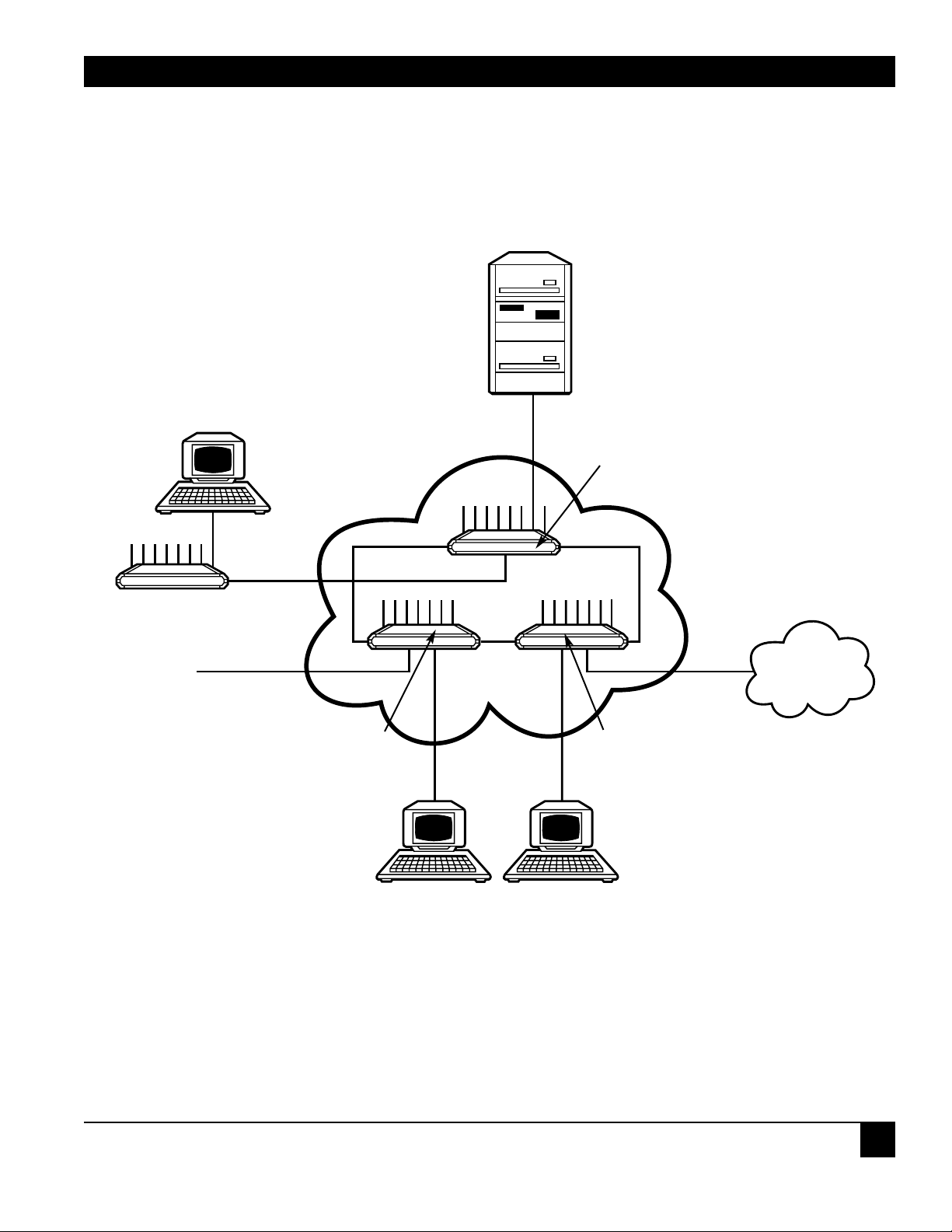
• Backbone for a low-cost private X.25 network with optional connection to the public network.
(See Figure 2-1.)
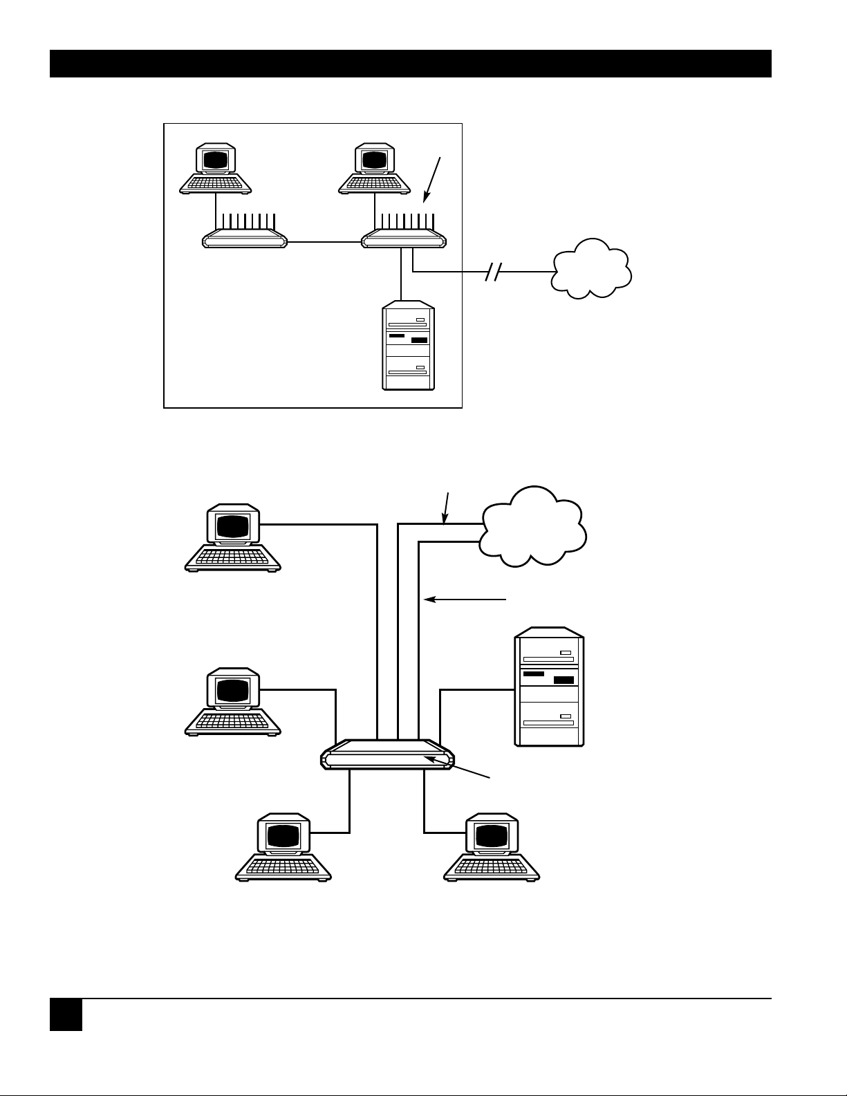
• Expansion of the number of asynchronous inputs, using statistical multiplexors (proprietary).
(See Figure 2-2.)
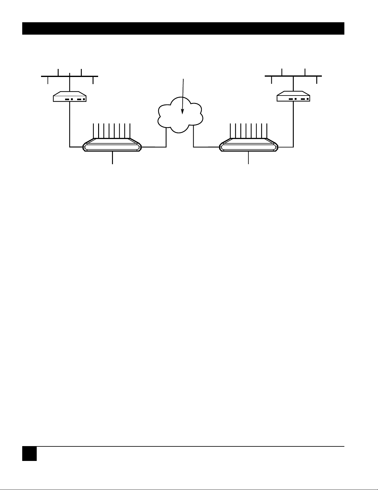
• Public Network access via redundant links. (See Figure 2-3.)
• Running asynchronous data in X.25 packets over Frame Relay. (See Figure 2-4, part a.)
• Running asynchronous data directly over Frame Relay (SLIP protocol over Frame Relay).
(See Figure 2-4, part b.)
2. Introduction
Page 8
CHAPTER 2: Introduction
7
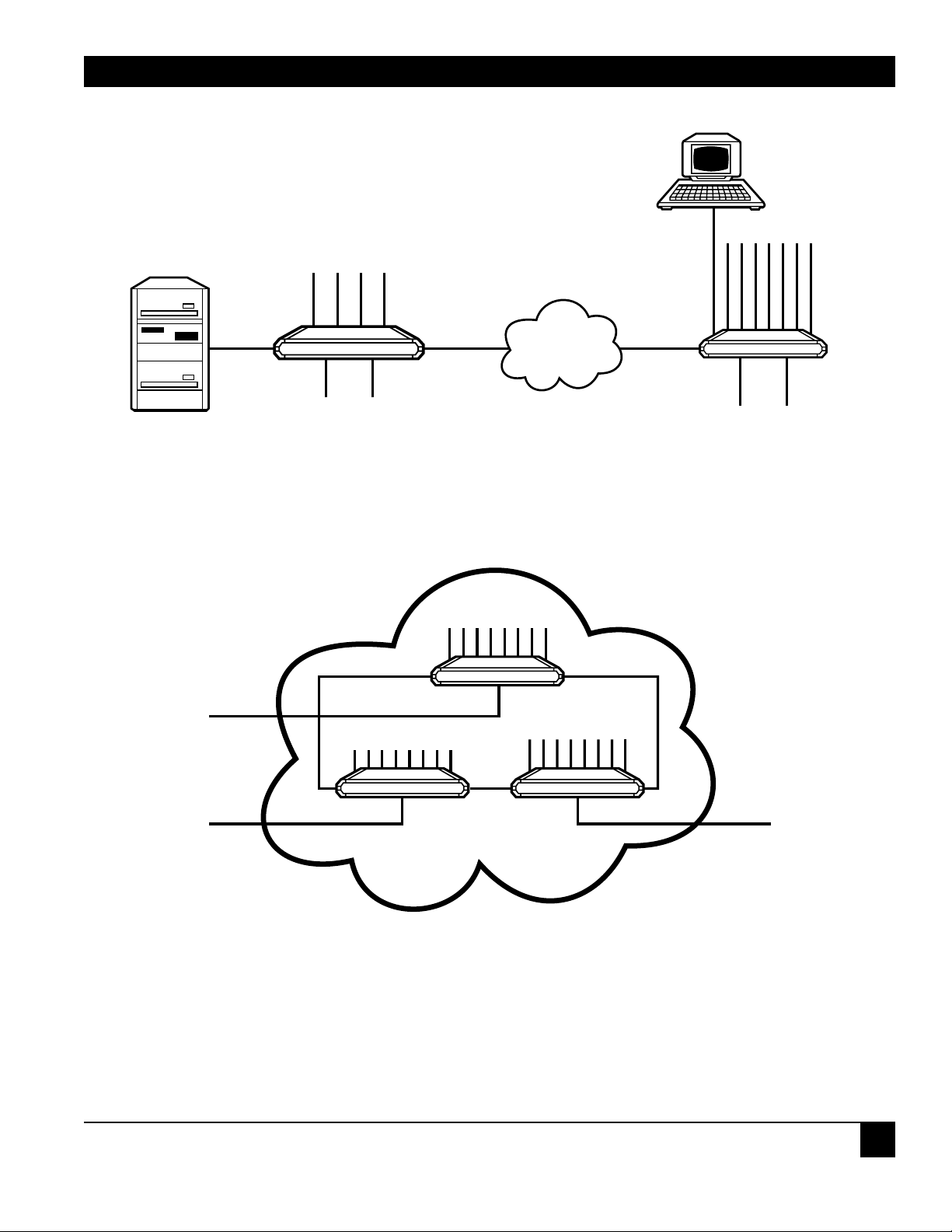
• Routing between several Frame Relay devices or networks (Frame Relay to Frame Relay switching).
(See Figure 2-5.)
• Connection of devices supporting HDLC protocol to the X.25 or Frame Relay network.
(See Figure 2-6.)
Figure 2-1. Fradswitch-8A serving as backbone for private X.25 data networks.
STAT MUX
STM LINK
X.25 LINK
X.25 LINK
X.25
NETWORK
X.25 PUBLIC
DATA
NETWORK
FRADSWITCH-8A
FRADSWITCH-8A
FRADSWITCH-8A
Page 9
FRADSWITCH-8A, FRADSWITCH-16A, FRADSWITCH-24A
8
Figure 2-2. Fradswitch-8A providing X.25 switching and async channel expansion.
Figure 2-3. Fradswitch-8A serving as a PAD with redundant link and load sharing.
One link configured as async channel.
FRADSWITCH-8A
STM
X.25
X.25
64 Kbps
COMPUTER
STAT-24
(MX868A)
X.25
PUBLIC
NETWORK
X.25 PUBLIC
NETWORK
ASYNC LINK
ASYNC
CHANNELS
X.25 NETWORK ACCESS
128 Kbps
X.25 REDUNDANT NETWORK ACCESS
19.2 Kbps
FRADSWITCH-8A
Page 10
CHAPTER 2: Introduction
9
Figure 2-4. (a) Fradswitch-8A operating as a switch at the user side: Conversion of Frame Relay to X.25.
(b) Fradswitch-8A operating as a FRAD at the user side: Conversion of Frame Relay to async.
Figure 2-5. Fradswitch-8A serving as a backbone for Frame Relay private data network.
X.25
FRAME
RELAY
FRAME
RELAY
FRAME
RELAY
FRAME
RELAY
FRAME
RELAY
PRIVATE
DATA
NETWORK
FRAME
RELAY
FRAME
RELAY
NETWORK
ASYNC
FRADSWITCH-8A
FRADSWITCH-8A
FRADSWITCH-8A
FRADSWITCH-8A
FRADSWITCH-8A
(A)
(B)
Page 11
FRADSWITCH-8A, FRADSWITCH-16A, FRADSWITCH-24A
10
Figure 2-6. Fradswitch-8A connecting HDLC devices over X.25 or Frame Relay.
2.3 X.25 Link Features
When the Fradswitch links are configured for X.25, they operate synchronously at data rates up to
2.15 Mbps. The links interface is DTE or DCE, and the data rate is determined by the external clock rate.
You can order the Fradswitch with interfaces for RS-232/V.24, X.21, or V.35.
The links packet size supported by the Fradswitch is configurable (up to 4096 bytes), and the frame window
range is selectable in the range of 1 through 7 (for modulo-8 operation), or 1 through 127 (for modulo-128
or extended operation).
Fradswitch links fully support switched virtual circuits (SVC) and permanent virtual circuits (PVC). The links
protocol is LAPB per ITU X.25, and the Fradswitch can act as either DTE or DCE with respect to the layer 2
and layer 3 protocols.
2.4 Frame Relay Link Features
When a link is configured for Frame Relay, packets are processed as follows. If the Fradswitch is located at
the user side (acting as an end device), the received Frame Relay packets are converted into async or X.25
format and are routed to the appropriate port. (See Figure 2-4.) If the Fradswitch is located at the network
side, the received Frame Relay packets are routed to another Frame Relay link. (See Figure 2-5.)
Acting as a FRAD (Frame Relay Assembler/Disassembler), the Fradswitch can either convert the
asynchronous data into X.25 packets and concentrate the packetized data stream over the Frame Relay
link, or directly run asynchronous data over Frame Relay.
FRADSWITCH-8A
FRADSWITCH-8A
ETHERNET
BRIDGE
BRIDGE
TRANSPARENT
HDLC
X.25 OR
FRAME
RELAY
X.25 OR
FRAME
RELAY
NETWORK
X.25 OR
FRAME
RELAY
TRANSPARENT
HDLC
ETHERNET
Page 12

CHAPTER 2: Introduction
11
The Fradswitch employs a unique funneling method for controlling network congestion and moderating
feeder throughput speed.
CCLM and LMI management protocols are supported, and operation is in compliance with ANSI T1.606,
T1.619, T1.617 Annex D, and ITU Q.922, Annex A.
2.5 HDLC Link Features
The Fradswitch links can be programmed to operate with transparent HDLC allowing computers, bridges,
and HDLC communication devices to be connected over X.25 or Frame Relay networks. The HDLC
protocol is encapsulated over the X.25 or Frame Relay protocol, providing end-to-end transparent
operation. (See Figure 2-6.)
2.6 ASYNC Link Features
The Fradswitch links can be programmed to operate asynchronously, allowing connection of asynchronous
devices to the links. When programmed to operate as async, the links operate like Fradswitch series async
channels with all the standard facilities. (See Figure 2-3.)
2.7 Buffer Capacity
The Fradswitch series uses dynamic on-demand allocation of data buffers, in accordance with the channels
and links traffic conditions. The Fradswitch series automatically changes the buffer allocation on-line,
to make the best possible use of the free RAM capacity.
The standard Fradswitch RAM size is 256 KB; as an option, the Fradswitch can be ordered with
1024 KB RAM, to increase the throughput in environments that generate high traffic volumes.
2.8 Asynchronous Channel Interface Characteristics
Channel operation is asynchronous. The asynchronous word format is user-configurable, by means of
proprietary extension to the ITU X.28 basic set of commands. For flexibility in applications, flow control
can be performed either by software (X-ON/X-OFF) or by hardware handshaking.
All of the Fradswitch channels have RS-232/V.24 DCE interfaces. Each channel has its own eight-pin
RJ-45 connector.
2.9 Channel PAD Characteristics
The Fradswitch includes eight essentially independent PADs, one for each channel. All the channel
PADs share the three X.25 physical links. The channel PADs support multiple sessions with independent,
user-selected session profiles. This means that any user connected to one of the Fradswitch channels can
simultaneously conduct several virtual circuits carried by different logical channels. The maximum number
of sessions per channel is up to 4.
Page 13

FRADSWITCH-8A, FRADSWITCH-16A, FRADSWITCH-24A
12
The Fradswitch supports four call-initiation methods, independently selectable for each channel.
1) Manual (regular) call initiation, whereby the user provides all the information required to set
up the call by entering an X.28 command.
2) Mnemonic call initiation, whereby the user need only enter a mnemonic (call ID). The channel PAD
then retrieves the call-setup information from the Fradswitch’s memory.
3) Automatic call initiation (autocall). The call is automatically initiated as soon as the user equipment is
turned on, in accordance with predefined call-setup information stored in the Fradswitch’s memory. To
completely automate the call setup, a user-defined sequence of X.28 commands (alias) can automatically
be sent after the call is set up. The sophisticated Fradswitch autocall mode includes two measures that
allow for the reliable setup of the desired call:
Automatic call setup retry: the user can specify the number of retries, and the interval between
consecutive retries.
An alternative address for call setup that is automatically used when it is not possible to set up
a call to the first address.
4) Use of permanent virtual circuit (PVC). The call is automatically set up by the X.25 network switch,
in accordance with predefined call-destination data requested at subscription time.
2.10 ITU Facilities
The ITU X.2 facilities supported by the Fradswitch series are:
• Closed user groups
• Fast select
• Reverse charging
• Throughput class negotiation
• Packet and window size negotiation
• Charging information
• Network user identification (NUI)
2.11 Command Facility Features
The Fradswitch series channel PADs operate under the control of a central command facility.
The command facility can be used to perform the following activities:
• Set up the individual channel PAD configuration parameters
• Determine common Fradswitch configuration parameters
• Perform statistics and performance monitoring on the Fradswitch and its channels
• Perform diagnostic activities
Page 14

CHAPTER 2: Introduction
13
The command facility supports the configuration of both the local and the remote channel PADs. It includes
a help function, which provides information on the available PAD commands, and on the purpose and
format of each command.
The Fradswitch’s command facility can be accessed from any channel, and from any place in the X.25
network. Simultaneous access from several channels is possible, but a warning is given if a user connects
to the facility when someone else is already connected to the command facility.
Password protection prevents unauthorized persons from using the command facility. The Fradswitch’s
command facility supports two password levels:
1) Super user password, which allows performance of all the activities (this password is usually known
only to the system administrator).
2) Regular user password, which provides access to functions that do not change the system status
(that is, a regular user cannot perform system-wide configuration and diagnostics activities).
Using the command facility, each Fradswitch channel can be independently configured for different
profiles, including profiles dedicated to specific sessions. The command facility can also be used to prepare
a local library of call-setup sequences, network user identification data, and predetermined command
sequences that can be accessed by all the Fradswitch users, and that can be assigned to specific channels
for use in automatic call setup.
The amount of information that can be stored is limited by the available nonvolatile storage capacity.
The required storage is provided by a nonvolatile memory (NVRAM). The standard capacity of the
Fradswitch’s NVRAM is 2 KB. As an option, when a larger number of parameters, profiles, and other
user-defined information must be stored, the Fradswitch can be ordered with increased NVRAM capacity, up
to a maximum of 32 KB.
2.12 Configuration Features
The configuration functions provided by the Fradswitch command facility allow the preparation
of the following data:
• Individual channel configuration
• Preparation of profiles
• Preparation of mnemonic call-setup sequences (call IDs)
• Preparation of predefined X.28 command sequences (aliases)
• Preparation of network user identifications (NUI)
• Definition of PVCs
• Definition of X.25 link-configuration parameters
• Definition of system-management parameters
• Definition of data routes
Page 15

FRADSWITCH-8A, FRADSWITCH-16A, FRADSWITCH-24A
14
For activities that involve repetitive preparation of the same set of parameters, such as channel
configuration, profiles, call IDs, etc., the Fradswitch provides a time-saving duplicate function, which
allows copying an already-prepared data set as a basis for the preparation of a new set. Another valuable
convenience is the display of reports that summarize the existing data for each type of configurable
data item.
In addition, on-line help is available in the preparation of configuration data. The help information
includes concise definitions of parameters and specifies the available range of values.
2.13 Link-Configuration Capabilities
The Fradswitch link-configuration functions provide the following capabilities for each of the links:
• Definition of the local X.25 address
• Selection of layer 2 and layer 3 modules (DCE or DTE)
• Selection of the various LAPB timers and parameters
• Selection of default window and packet sizes
• Definition of logical-channel allocation (permanent, incoming, two-way, and outgoing)
2.14 System-Parameter Configuration Capabilities
The Fradswitch system-parameter configuration functions provide the following capabilities:
• Definition of a device identification for the local Fradswitch
• Selection of default PAD prompt
• Selection of default software flow-control characters (XON, XOFF)
• Changing of user and super-user passwords
• Definition of herald and bulletin messages
• Definition of event-reporting addresses, and the associated reporting masks
• Definition of event-reporting intervals
2.15 System-Control Capabilities
The Fradswitch system-configuration functions provide the following capabilities:
• Logical connection/disconnection of the X.25 link.
• Clearing of selected sessions.
• Setting of the date and time of the internal real-time clock.
• Resetting of statistics counters.
Page 16

CHAPTER 2: Introduction
15
• Compression of data stored in the Fradswitch’s nonvolatile memory, to allow maximum use of the
available storage capacity. The compression is performed by rearranging the data stored in the memory,
to close gaps between data blocks that appear naturally when the stored information is modified.
• Resetting and reloading of the default configuration. This function allows a remote supervisor
to perform these activities, which would otherwise require the dispatching of service personnel.
2.16 Remote System Monitoring
The Fradswitch includes an automatic event-reporting facility that allows the transmission of statistics
and status data to selected X.25 destinations.
The automatically reported information can include periodic system status information, and event reports
according to mask definitions. (The different events are: SYNC status has changed, RTS status has changed,
and power on [Reset].) A report is sent each time an event occurs.
With the Fradswitch’s system-management configuration facility, you can define two destinations, then
decide which information is transmitted to each destination by means of event-reporting masks. It is
therefore possible to program the Fradswitch series to transmit the same reports to both destinations,
and thus to make sure that the reports will reach a management station, or to send different types
of information to different locations.
2.17 Status and Statistics Collection and Reporting Capabilities
The Fradswitch has an advanced statistics-collection and status-reporting facility. This facility permits the
system administrator to display on demand detailed information on the operation and performance of the
X.25 links, and take snapshots that show the status of the Fradswitch series, the utilization of the X.25 links,
and the status of the individual channels. The information obtained by means of the statistics function
allows the system manager to monitor system performance, detect bottlenecks and transmission problems,
decide whether more NVRAM is needed, and troubleshoot on-line user channels.
The information displayed by means of the statistics function includes:
• Fradswitch system data:
Fradswitch identification (its device ID).
The programmed X.25 mode (DTE or DCE).
RAM size.
NVRAM size and current percentage of utilization.
• Fradswitch system status:
The current size (number of characters per buffer) of the data buffers.
The current total number of data buffers, and the number of free buffers.
• System history data, collected since the last resetting of the statistics counters:
Page 17

FRADSWITCH-8A, FRADSWITCH-16A, FRADSWITCH-24A
16
Total number of frames transmitted and received by layer 1 (the physical layer).
Total number of information frames transmitted and received by layer 2 (the link control layer).
Total number of information frames transmitted and received by layer 3 (the X.25 layer).
Current X.25 synchronization status, and the total number of X.25 synchronization losses.
The average number of data buffers in the Fradswitch “pool,” and the recorded minimum
number of buffers in this pool.
• Asynchronous channels status. The following information is available for each channel:
The subaddresses of each channel.
The current channel operating mode (data transfer/command mode).
The current status (free/engaged) and the software flow control state.
The logical channel numbers used by each channel, and the address reached through
each logical channel.
The number of active logical channels and active sessions.
The number of buffers currently allocated to the transmit (to network) and receive
(to user) directions.
Autocall ID (mnemonic) configured to the channel.
The number of the profile currently used by the channel, and the current values
of the individual PAD parameters.
The state of the channel RTS line (when relevant).
• X.25 links status. The following information is available for each channel:
Protocol, synchronization state, and transmission mode (DCE or DTE).
Current allocation of logical channels (per type) within the logical group in use, the number
of active channels, and the total number of layer 3 information frames transmitted through
each type of logical channel.
• Logical channel status and the current values of the main protocol variables.
• Physical layer (layer 1) driver statistics:
Total number of frames transmitted and received by layer 1 (the physical layer).
The number of R frames waiting in the buffers.
The physical layer state, and the state of the CD and CTS interface lines.
Page 18

CHAPTER 2: Introduction
17
• LAPB (layer 2) statistics:
Total number of I, RR, RNR, REJ, and FRMR frames transmitted and received by layer 2.
Number of transmission and reception errors.
LAPB state.
Current frame size.
•X.25 (layer 3) statistics:
Total number of I, clear, reset, and restart packets transmitted and received by layer 3.
Number of logical group in use.
Current packet size.
2.18 Diagnostic Features
Upon power-up or after reset, the Fradswitch performs a self-test, during which all its circuits are checked. If
there is a malfunction, the ERR indicator on the Fradswitch lights. The Fradswitch series also has diagnostic
functions that you can use to test it. See Chapter 5 of the Packet Switching Guide for more information.
Page 19

FRADSWITCH-8A, FRADSWITCH-16A, FRADSWITCH-24A
18
This chapter provides mechanical and electrical installation procedures for the Fradswitch.
The Fradswitch is delivered completely assembled. It’s designed to be installed as a desktop unit
or to be mounted in a 19-inch rack.
After installing the unit, refer to Chapter 2 of the Packet Switching Guide for system configuration
information and procedures.
3.1 Unpacking
Perform a preliminary inspection of the equipment container before unpacking the unit.
Evidence of damage should be noted and reported immediately. Unpack the equipment as follows:
1. Place the container on a clean flat surface, cut all straps, and open or remove the top.
2. Take out the Fradswitch carefully and place it securely on a clean surface.
3. Inspect the Fradswitch for damage.
3.2 Site Requirements
Power The Fradswitch should be installed within 5 feet (1.5 m) of an easily accessible grounded
AC outlet capable of furnishing 115- or 230-VAC, in accordance with the nominal supply
power of your Fradswitch.
Data-Channel
Connections The Fradswitch has eight, sixteen, or twenty-four RJ-45 connectors, one for each
asynchronous data channel. Appendix A of the Packet Switching Guide provides pin
allocations.
Main Links
Connections The Fradswitch has three main links connectors. The main links connector depends
on the ordered interface:
• RS-232/V24: 25-pin D-type, female connector
• X.21: 15-pin, female connector
• V.35: 34-pin, female connector
Appendix A in the Packet Switching Guide provides the pin allocations.
Front- and
Rear-Panel
Clearance When the Fradswitch is installed in a 19-inch rack, allow at least 36 inches (90 cm) of
frontal clearance for operator access. Allow at least 4 inches (10 cm) clearance at the
rear of the unit for interface cable connections.
3. Installation
Page 20

CHAPTER 3: Installation
19
Ambient
Requirements The ambient operating temperature of the Fradswitch should be 32 to 122°F (0 to 50°C),
at a relative humidity of up to 90%, noncondensing.
3.3 Fradswitch Hardware Configuration Information
3.3.1 GENERAL
INFORMATION
The Fradswitch contains three different types of printed circuit boards (see Figure 3-1):
• The main board. This board contains most of the Fradswitch circuits, and has two jumpers.
• The extension board.
• Three main link interface boards, which determine the interface type. The appropriate board
is factory-installed in accordance with your order, and is not field-replaceable. See Section 3.3.3
for more information; it provides information on the functions of the internal jumpers, and provides
step-by-step instructions for setting these jumpers. The default settings for each jumper are also listed.
NOTE
The default settings of the Fradswitch jumpers are usually suitable for most applications.
Check the default positions explained below. If your requirements are different, then before
you install the Fradswitch, set its internal jumpers in accordance with your requirements,
as explained below.
• All the other configuration actions are performed using the Fradswitch command facility, after the
installation is completed. Information and detailed instructions for these operations appear in
Chapter 2 of the Packet Switching Guide.
Page 21

FRADSWITCH-8A, FRADSWITCH-16A, FRADSWITCH-24A
20
Figure 3-1. Fradswitch-8A boards.
3.3.2 INTERNAL JUMPERS
WARNING!
In order to avoid the possibility of electrical shock, always turn the power switch off and
disconnect the power cable from mains before opening the Fradswitch.
The Fradswitch has two internal jumpers, designated JP1 and JP2. Refer to Figure 3-2 and use the following
information.
CH GND jumper, JP1 This jumper controls the connection between the signal ground lines to the chassis
ground lines. The appropriate position must be determined by the installation
manager. The jumper has two positions: GND CON (signal ground connected to
chassis ground) and DIS (signal ground disconnected from chassis ground). The
factory setting is DIS.
INTERFACE
BOARD
EXTENSION
BOARD
MAIN
BOARD
PW
R
A
MAIN
COVER
B
C
1
CHANNELS
2
3
4
5
6
7
8
SYNC
A
B
C
TEST
OVF
TEST
RESET
1
2
3
4
FRADSWITCH-8A
5
6
7
8
Page 22

CHAPTER 3: Installation
21
INIT–NOR
jumper, JP2 This jumper is used to select the default set of configuration parameters stored
in the Fradswitch. The jumper has two positions:
NOR Normal operation. The Fradswitch uses the parameters
selected by the user during the last configuration session.
INIT Initialization. When it is turned on, the Fradswitch loads the default
configuration (determined by the factory and common to all the
Fradswitch series units). To select the default configurations, use the
procedure described in Section
3.10 of the Packet Switching Guide.
The factory setting is NOR.
Figure 3-2. Fradswitch-8A, identification of internal jumpers.
JP1
GND
CON
DIS
JP2
INIT
NOR
Page 23

FRADSWITCH-8A, FRADSWITCH-16A, FRADSWITCH-24A
22
3.3.3 INTERFACE B
OARD
The Fradswitch is available with three types of removable interface boards:
• V.24 (RS-232) interface for DTE and DCE.
• V.35 interface for DTE and DCE.
• X.21 interface for DTE.
WARNING!
In order to a void the possibility of electrical shock, always turn the power switch off and
disconnect the power cable from the wall plug before opening the Fradswitch.
Each interface board is configured as either DCE or DTE.
The interface board determines the physical layer configuration of a Fradswitch link.
When the board is a DCE interface board, the link must be used with a flat cable to connect to a terminal.
The link receives its clock from outside and the clock parameter must be configured as external clock (see
Section 2.3 in the Packet Switching Guide).
When the board is a DTE interface board, the link uses the Fradswitch series internal clock, and the
clock parameter must be configured as internal clock (see Section 2.3 in the Packet Switching Guide).
3.3.4 J
UMPER SETTING PROCEDURE
WARNING!
In order to avoid the possibility of electrical shock, always turn the power switch off and
disconnect the power cable from wall plug before opening the Fradswitch.
Access the printed circuit board of the Fradswitch by opening the screw fastening the top cover to the case,
and removing the top cover.
Refer to Figure 3-2 and identify jumper locations and settings. Change settings as required.
Reinstall the Fradswitch’s cover, and fasten its screw. Do not exert excessive torque while tightening
these screws.
Page 24

CHAPTER 3: Installation
23
3.4 Installation in 19-inch Racks
The Fradswitch can be installed in 19-inch racks. Unit height is 1U (1.75"). The width of the Fradswitch
is slightly less than the available mounting width.
An adapter kit provides the hardware necessary for installation of the Fradswitch in 19-inch racks.
WARNING!
Disconnect the units from AC power while performing the following procedures.
The rack adapter kit for the installation includes two short brackets, which are fastened by means of screws
to the two side walls of the case, as shown in Figure 3-3.
To prepare the unit for rack installation, attach the two brackets to the side walls of the unit. Each bracket
is fastened by means of two screws (with flat washers), which are inserted into the two front holes on the side
wall (nuts are already in place, on the inner side of the wall).
After fastening the brackets, the unit is ready for installation in the 19-inch rack. Fasten the brackets to the
side rails of the 19-inch rack by means of four screws (not included in the kit), two on each side.
Figure 3-3. Installation of Fradswitch-8A in a 19-inch rack.
PWR
NAIN
A
B
C
1
2
CHANNELS
3
4
5
6
7
8
SYNC
SYNC
A
A
B
B
C
C
ERR
OVF
TEST
R
E
S
E
T
1
2
3
4
5
F
R
A
6
D
S
W
7
IT
C
H
8
BRACKETS
-8
FASTENING
FLATWASHER
SCREW 4-40
(4 PLACES)
Page 25

FRADSWITCH-8A, FRADSWITCH-16A, FRADSWITCH-24A
24
3.5 Cable Connections
The Fradswitch has three connectors located on the rear panel that serve the X.25 links,
and RJ-45 connectors located on the front panel for the asynchronous data channels.
3.5.1 ASYNCHRONOUS DATA-CHANNEL CONNECTIONS
Fradswitch channel interfaces are configured as data communication equipment (DCE) interfaces, thereby
allowing direct connection, via RS-232 port cables, to data terminal equipment (DTE). When modems are
used to extend the range (tail-end circuits), cross-over cables are required. Channel interfaces are
asynchronous, so clock signals are not supported or required.
Appendix A in the Packet Switching Guide lists pin allocation in Fradswitch series data-channel connectors,
and provides typical wiring diagrams for straight-through and cross-over cables.
3.5.2 X.25 L
INK CONNECTION
Fradswitch X.25 link interfaces are configured as DTE interfaces, intended for connection to synchronous
modems that are capable of providing the clock signals that determine the Fradswitch’s X.25 link data rate.
The X.25 link connectors type depends on the Fradswitch interface:
• RS-232/V24: 25-pin D-type, female connector
• X.21: 15-pin, female connector
• V.35: 34-pin, female connector
Appendix A in the Packet Switching Guide provides the pin allocations for the various X.25 links connectors.
NOTE
The user data cables and the X.25 links cables should be shielded, in order to comply with
FCC rules. The Fradswitch series and its data interfaces will work well even if the cables
are not shielded, but some radio interference may occur.
Page 26

CHAPTER 3: Installation
25
3.5.3 POWER CONNECTION
AC power should be supplied to the Fradswitch through the 5-foot (1.5-m) power cable terminated by a
standard 3-prong plug. Connect the cable between the AC mains connector on the Fradswitch’s rear panel
and a standard grounded AC outlet.
WARNING!
Before switching on this instrument, the protective earth terminals of this instrument must
be connected to the protective ground conductor of the (mains) power cord. The mains
plug must be inserted only in a socket outlet provided with a protective earth contact. The
protective action must not be negated by use of an extension cord without a protective
conductor (grounding).
Make sure that only fuses with the required rated current, as marked on the Fradswitch’s
rear panel, are used for replacement. Never use repaired fuses or short-circuit fuse
holders.
Whenever it is likely that the protection offered by fuses has been impaired, the instrument
must be made inoperative and be secured against any unintended operation.
3.5.4 G
ROUNDING
Any interruption of the protective (grounding) conductor (inside or outside the instrument)
or discon-necting the protective earth terminal can make this instrument dangerous. Intentional
interruption is prohibited.
Page 27

FRADSWITCH-8A, FRADSWITCH-16A, FRADSWITCH-24A
26
4.1 Controls, Indicators, and Connectors
Table 4-1 lists the Fradswitch’s front-panel indicators and connectors. The numbers under the heading
“Item” refer to the identification numbers in Figure 4-1.
Figure 4-1. Fradswitch-8A front-panel controls, indicators, and connectors.
Table 4-1. Fradswitch-8A controls, indicators, and connectors
Item Control, Indicator, or Connector Function
1 PWR Indicator Lights when the Fradswitch is powered.
2 Main Link Activity Indicators Indicators, one for each main link, light when the
corresponding link is active (receives or transmits
frames).
3 Channel Activity Indicators Indicators, one for each channel, light when the
corresponding channel is active (receives or
transmits data).
4. Operation
32 4 5
MAIN
PWR
1
CBA
CHANNELS
7654321 CBA
SYNC
8
ERR
6
7
8
RESETTESTOVF
12345678
9
FRADSWITCH-8A
Page 28

CHAPTER 4: Operation
27
Table 4-1. Fradswitch-8A controls, indicators, and connectors (continued)
Item Control, Indicator, or Connector Function
4 SYNC Indicator Indicators, one for each main link, indicate
Fradswitch synchronization status.
Condition
Indication
Off Fradswitch not powered.
On Fradswitch powered and
synchronized with the corres-
ponding X.25 DTE or DCE
peer.
Flashing Fradswitch powered, but
(continuous) not synchronized with the
corresponding X.25 DTE
or DCE peer.
5 ERR Indicator Lights when a hardware malfunction was
detected during the self-test automatically
performed upon power-up, or after pressing
the RESET pushbutton.
6 OVF Indicator Lights when the Fradswitch’s buffers are full. In
a properly designed system, this condition usually
indicates that one of the DTE units connected to
the Fradswitch does not respond to the flowcontrol commands sent by the Fradswitch, a
condition that could be caused by incorrect
configuration of the Fradswitch.
7 TEST Indicator Lights to indicate that the Fradswitch is in the
diagnostics mode (one of the test loops active)
or that one of its channels is connected to the
Fradswitch command facility. In either case,
traffic is interrupted.
8 RESET pushbutton Resets Fradswitch internal circuits (including
the data buffers) and initiates the power-up
self-test.
9 Channel Connectors Connection to Fradswitch channels
(one connector per channel).
Page 29

FRADSWITCH-8A, FRADSWITCH-16A, FRADSWITCH-24A
28
Table 4-2 lists the functions of the Fradswitch’s rear-panel controls and connectors. The numbers
under the heading “Item” refer to the identification numbers in Figure 4-2.
Figure 4-2. Fradswitch-8A rear-panel controls and connectors.
Table 4-2. Fradswitch-8A rear-panel controls and connectors
Item Control or Connector Function
1 Power Connector AC power connector with integral fuse
2 Power Switch Turns the Fradswitch on
3 X.25 Links Connectors Connection to X.25 link
321
POWER
230V/F - 0.2A S.B
115 VAC/F - 0.4A S.B
MAIN C MAIN B MAIN A
Page 30

CHAPTER 4: Operation
29
4.2 Operating the Fradswitch
After being prepared for operation as explained in Section 4.1, the Fradswitch normally operates
unattended. Operator intervention is required only when the Fradswitch is set up for the first time
or must be adapted to new operational requirements.
NOTE
Fradswitch configuration is stored in a nonvolatile memory, and is not affected when
power is turned off.
Connect the power cable to the Fradswitch’s rear power connector, then turn the power switch ON.
The PWR indicator should light.
If none of the links to the X.25 DTE/DCE peers are yet operational, the SYNC indicators on the Fradswitch
will flash. Wait until one of the links becomes operational, and check that the corresponding SYNC indicator
stops flashing and lights continuously.
Check that after a short interval (during which the Fradswitch performs its self-test), the ERR, OVF,
and TEST indicators go out.
During normal operation, the PWR, SYNCs, and MAINs indicators should light continuously and the TEST,
OVF, and ERR indicators must remain off.
Channel activity indicators flash according to the traffic load, and go out when the channel is idle.
Note that when the TEST indicator lights, traffic is interrupted, even if all the other indications are normal.
To turn the Fradswitch off, set the power switch to OFF.
4.3 What to Do in Case of Malfunction
In case a problem occurs, the following actions will help you to return the Fradswitch to normal operation.
• Check that the Fradswitch is powered (PWR indicator should light).
• Check that the cables are properly connected.
• Check that the equipment connected to the Fradswitch is powered and operates normally.
• Check the Fradswitch’s indicators.
• Check the configuration of the Fradswitch PAD and that of the remote PAD or
switch correspond to the requirements of the equipment connected to its channels.
If the preliminary checks do not correct the problem, press RESET, or turn the Fradswitch off, then turn it
on again. If the problem repeats, refer to Chapter 7 in the Packet Switching Guide for additional operations.
Page 31

FRADSWITCH-8A, FRADSWITCH-16A, FRADSWITCH-24A
30
This section provides concise operating instructions for the Fradswitch. Remember that the information
appearing in this chapter is intended to help you start using the Fradswitch; it is not a replacement for the
detailed operating instructions contained in the Packet Switching Guide.
The instructions assume that the Fradswitch is configured in accordance with the factory defaults, explained
in Section 1.8 of the Packet Switching Guide. The factory defaults are suitable for most applications, so in many
applications it is necessary to change only the parameters that are related to the subscription terms (such as
the X.25 address, the packet and window size, the X.25 transmission mode, etc.). If you want to send packets
out from the Fradswitch, you must also change your routing table, because the default routing table directs
all packets into the Fradswitch.
Before performing any of the activities described in this chapter, keep in mind that your X.25 data services
provider, or your system administrator, may not allow you to perform certain activities. Passwords may have
been used to restrict the access to certain functions.
5.1 Connecting to the Fradswitch Command Facility
If the Fradswitch is operating, use the following procedure:
1) Turn your DTE on and configure it for the appropriate communication parameters. The default
values are 9600 bps, 1 start bit, 8 data bits, no parity, 1 stop bit, flow control disabled.
2) Connect the DTE to one of the Fradswitch channels (for example, to channel 1).
3) Turn the Fradswitch on. After a short interval, you will see the Fradswitch herald message
(for example, FRADSWITCH-8A CHANNEL NUMBER 1), followed by the PAD prompt, *.
If the Fradswitch is already operating and the channel you are connected to is engaged in a call, type CTRL
P to exit the data transfer mode and obtain the PAD prompt *. After you see the PAD prompt, disconnect
the call by typing the command CLR <CR>. When the call is cleared, you will see CLR DTE, and the
following line shows the PAD prompt.
Type the connection command: CON 00 <CR>. You can also use the abbreviated form, C 0 <CR>. The
Fradswitch displays the opening screen (Figure 5-1) of the command facility, and the TEST indicator
on the Fradswitch’s front panel turns on.
5. Quick Start
Page 32

CHAPTER 5: Quick Start
31
Figure 5-1. Fradswitch-8A opening screen.
Enter the password. The factory-default password is a carriage return.
The Fradswitch sends the main menu of the command facility (Figure 5-2).
Figure 5-2. Main menu.
FRADSWITCH-8A COMMAND PORT
REV X.Y
ENTER FRADSWITCH-8A PASSWORD:
MAIN MENU
1) CONFIGURE
2) SYSTEM CONTROL
3) DIAGNOSTICS
4) STATUS and STATISTICS
5) LOGOUT
SELECT:
Page 33

FRADSWITCH-8A, FRADSWITCH-16A, FRADSWITCH-24A
32
5.2 Basic X.25 Configuration Procedures
The following text describes the configuration procedure for the basic application shown in Figure 5-3.
This configuration includes two X.25 PADs (in this case,
X.25 PAD 8) connected through a Fradswitch to a
public X.25 network. In this form we connect a private network to the X.25 public network. This procedure
is based on the default factory settings.
Figure 5-3. Basic Fradswitch-8A connection to an X.25 public network.
5.2.1 F
RADSWITCH LINK CONFIGURATION
The link configuration may require X.25 address (calling address) setting. Verification of the packet size,
window size, and transmission mode (DCE or DTE) is important to match the nearest X.25 peer data.
• Enter the Fradswitch command facility (see Section 5.1).
• On the Fradswitch main menu, select 1 (CONFIGURE), and then select 3 (Link).
• On the Fradswitch link configuration menu, select 3 (Update Link Parameters), and then enter 2
at the “Enter link number to update:” prompt.
• On the Fradswitch link 2 configuration screen, select 1 (Address) and then enter your subscribed
(calling address) address.
• Verify that your packet size and window sizes (parameters K and W) are correct and change them if
required according to your X.25 subscription data. On the Fradswitch X.25 link 2 configuration screen,
enter 2 for DTE/DCE parameter, and then enter 0 for DTE.
• On the Fradswitch X.25 link 2 configuration screen, select S (SAVE) and then press <CR> (EXIT).
ASYNC TERMINAL
123456789012 1X
123456789012 2X
X.25 PAD 8
1
1
2
3
FRADSWITCH-8A
DTE
DTE
DCE
DCE
DTE
2
X.25 PAD 8
X.25
NETWORK
MODEM
123456789012 0X
ASYNC TERMINAL
ASYNC TERMINAL
Page 34

CHAPTER 5: Quick Start
33
• Enter 1 at the “Enter link number to update:” prompt.
• Verify that the X.25 transmission mode is DCE. This section assumes that your matching
X.25 PAD 8
is configured as DTE.
• Repeat the above procedure for link 3.
• Return to the Fradswitch main menu, and select 2 (SYSTEM CONTROL).
• On the Fradswitch SYSTEM CONTROL menu, select 9 (Reset), and enter “y” at the “Are you sure
(y/n):” prompt.
5.2.2 F
RADSWITCH
ROUTING TABLE CONFIGURATION
The routing table consists of the various routes of the system. These routes determine how the different
packets will be switched. The required parameters for a route are the address and three possible destination
links.
The next sections assume that your X.25 address is 123456789012, that your number 1
X.25 PAD 8
subaddress is 1X, and that your number 2 X.25 PAD 8 subaddress is 2X. Refer to Figure 5-3.
NOTE
In the following text, the notation X means the digit where the X is written can have any
value.
• On the Fradswitch main menu, select 1 (CONFIGURE), and then select 9 (Routing table).
• On the Fradswitch routing table entry configuration menu, select 1 (Add routing table entry),
and then enter 1.
• On the Fradswitch routing table entry 1 configuration menu, select 1 (Destination link),
and then enter L (Local channels).
• On the Fradswitch routing table entry 1 configuration, select 4 (Address), and then enter address
1234567890120X. The last two digits 0X are the Fradswitch subaddress.
• On the Fradswitch routing table entry 1 configuration, select S (SAVE), and then press <CR> (EXIT).
• On the Fradswitch routing table entry configuration, select 1 (Add routing table entry), and then enter
2. Enter the address 1234567890121X, 1 for the first destination link, and then select S (SAVE) and press
<CR> (EXIT).
• On the Fradswitch routing table entry configuration, select 1 (Add routing table entry), and then enter
3. Enter the address 1234567890122X, 3 for the first destination link, and then select S (SAVE) and press
<CR> (EXIT).
• On the Fradswitch routing table entry configuration, select 3 (Update routing table entry), and then
enter 200.
• On the Fradswitch routing table entry 200 configuration, select 1 (Destination link), and then enter 2.
Verify that your address is XXXXXXXXXXXXXX, and then select S (SAVE) and press <CR> (EXIT).
• Return to the Fradswitch main menu, and select 2 (SYSTEM CONTROL).
Page 35

FRADSWITCH-8A, FRADSWITCH-16A, FRADSWITCH-24A
34
• On the Fradswitch system control menu, select 9 (Reset), and enter “y” at the “Are you sure (y/n):”
prompt.
After doing all of the above, the routing table will be shown as in Figure 5-4.
Figure 5-4. Basic Fradswitch connection routing table.
5.3 STM Protocol
5.3.1 STM LINKS
The STM protocol is a proprietary protocol used in some statistical multiplexors, such as Stat-4, Stat-8, and
Stat-24 (Part numbers MX864A, MX866A, and MX868A). The Fradswitch may be configured to link with
one of these STMs via any of its sync links to form a multichannel PAD.
The STM channels may be used as PAD channels. They may be configured as a PAD channel via the channel
configuration menu.
5.3.2 STM PTOTOCOL CONFIGURATION
1. In the MAIN MENU press option number 1 (CONFIGURE).
2. Press 3 (Link), then press 1 (Set Link Type).
3. Select any link number between 1 and 3.
4. Select Link type: 6 for Stat-4, 7 for Stat-8, or 8 for Stat-24. Press <return> or <enter>.
5. If you want to work with an internal clock, press 3 in the Link configuration screen
(Update Link Parameters). Select the link number you have chosen for the STM.
6. Press 1 for Internal Clock. You can work with baud rates of 9600, 19,200, or 38,400 Kbps. Note
that in order to work with an internal clock, the hardware of the link interface should be DCE.
7. Reset the Fradswitch.
8. The STM which is connected to the link number you have chosen should synchronize with the
Fradswitch within 30 seconds.
ID ADDRESS DESTINATION LINK
1ST 2ND 3RD
1 1234567890120X LOCAL 0 0
2 1234567890121X 1 0 0
3 1234567890122X 3 0 0
200 XXXXXXXXXXXXXX 2 0 0
Page 36

CHAPTER 5: Quick Start
35
9. The STM Async Channels are numbered according to the link number:
For link number 1, in Stat-8, they are numbered 101—108.
For link number 1, in Stat-24, they are numbered 101—124.
For link number 2, in Stat-8, they are numbered 201—208.
For link number 2, in Stat-24, they are numbered 201—224.
•
•
•
For link number 12 in Stat-8, they are numbered 1201—1208.
For link number 12 in Stat-24, they are numbered 1201—1224.
NOTE
The sub-channel addresses are “00” by default, and must be configured to another number
before use.
NOTE
Stat-4 channels do not work at present with X.28 parameters that is, the profiles defined in
the Fradswitch do not change the parameters already defined in the Stat-4.
5.4 Weight-Oriented Routing Function
Whenever a call command is issued, the interface from which the call is to be connected is selected using
a static routing table. The algorithm is very simple—the routing table is searched until an address match is
noted, and then the first synchronized link is selected.
New Implementation Builds a list of all links which have satisfied the following conditions:
• The link is synchronized (exception is a dialed link).
• There is at least one LCN available.
The selection between the links is set according to pre-defined priorities determined by the user.
The link priority is actually the load factor.
For example, if links 1, 2, and 3 get respectively the priorities 2, 5, and 6, then for every 13 calls
2 will be routed to the link 1, 5 to link 2 and 6 to link 3.
Page 37

FRADSWITCH-8A, FRADSWITCH-16A, FRADSWITCH-24A
36
The “stop search” field lets you limit the address match search, so you can define more than three routing
options to a given set of addresses. Furthermore, the “stop search” field allows restricting a subset of an
address set to a subset of links.
For example, consider the case of a Fradswitch-12A/S (our part number MT727A). The address 123456789
should be routed to link 1 only, the set of addresses 123456700-123456788 can be routed to links 2-7, and
every address 12000000-123456699 should be routed to links 8-12, in an increasing priority.
The screens below and on the next page show entries 1 through 5.
1) Link .........#no 6) Link prio .....#p
2) Link .........#no 7) Link prio .....#p
3) Link .........#no 8) Link prio .....#p
4) Address ......[]
5) Stop search ..[]
S) Save
CR) Exit
1) Link .........1 6) Link prio.....1
2) Link .........0 7) Link prio.....0
3) Link .........0 8) Link prio.....0
4) Address ......[123456789]
5) Stop search ..[1]
S) Save
CR) Exit
1) Link .........2 6) Link prio.....1
2) Link .........3 7) Link prio.....1
3) Link .........4 8) Link prio.....1
4) Address ......[1234567XX]
5) Stop search ..[1]
S) Save
CR) Exit
Page 38

CHAPTER 5: Quick Start
37
1) Link .........5 6) Link prio.....1
2) Link .........6 7) Link prio.....1
3) Link .........7 8) Link prio.....1
4) Address ......[1234567XX]
5) Stop search ..[1]
S) Save
CR) Exit
1) Link .........8 6) Link prio.....1
2) Link .........9 7) Link prio.....2
3) Link .........10 8) Link prio .....3
4) Address ......[12XXXXXXX]
5) Stop search ..[0]
S) Save
CR) Exit
1) Link .........11 6) Link prio .....4
2) Link .........12 7) Link prio .....5
3) Link .........0 8) Link prio.....6
4) Address ......[12XXXXXXX]
5) Stop search ..[1]
S) Save
CR) Exit
Page 39

FRADSWITCH-8A, FRADSWITCH-16A, FRADSWITCH-24A
38
5.5 Management Procedures
All of the management procedures described below are started by entering a command when the channel
is in the command mode.
Recalling
the PAD If the channel is in the command mode, you can see the PAD prompt on the monitor
of your data equipment. If not, recall the PAD by typing CTRL P.
Invoking the
Help Function Type H and then press the <CR> key.
Loading a
Profile To load a new profile, type PROF, then number of the new profile (1 through 200),
and then press the <CR> key.
Checking PAD
Parameter
Values Type PAR?nn,nn,...,nn and then press the <CR> key. nn are parameter numbers.
To see the values of all the parameters, do not enter numbers after the ?.
Setting PAD
Parameter
Values Type SETnn:vv,nn:vv,...,nn:vv and then press the <CR> key. nn is a parameter number
and vv is the value of parameter nn.
If you want to see the new parameter values, type a ? after SET.
5.6 Calling Procedures
In order to make a manual call to any destination, the Fradswitch channel must be in command mode. If the
channel is in the command mode, you can see the PAD prompt (*) on the monitor of your data equipment.
If not, recall the PAD by typing CTRL P.
Local Call To call another user connected to the same Fradswitch, type C, the number of the
channel the other user is connected to, and then press the <CR> key. You only need
to enter the subaddress of that user (2 digits max.).
Manual Call to
another X.25
Destination To call a remote X.25 destination, type C, the desired X.25 address, and then press the
<CR> key.
If the remote X.25 destination includes a subaddress, type C, the desired X.25 address,
the subaddress, and then press the <CR> key.
To request a specific facility you are allowed to use, type the facility after the C, and
type a hyphen (-) at the end of the block, before the X.25 address. If you want to
request several facilities, insert commas between each pair of codes.
Page 40

CHAPTER 5: Quick Start
39
Mnemonic Call If the same destination is often used, it can be called by a mnemonic call, provided
the call-initiation information has been defined by means of the Call ID function
(see Chapter 2 in the Packet Switching Guide).
To use the mnemonic call initiation command, type C, the mnemonic, and then press
the <CR> key.
Multiple
Sessions To change the current session, or to start a new session, use the following procedure:
• If an active call is handled by the current session, type CTRL P to obtain
the PAD prompt.
• When the PAD is free, type SES, the number of the desired session
(1 through 4), and then press the <CR> key.
• The PAD prompt reappears. If the new session number is not 1, the
session number (2, 3, or 4) appears to the left of the PAD prompt
(separated by one space).
Page 41

NOTES
Page 42

1000 Park Drive • Lawrence, PA 15055-1018 • 724-746-5500 • Fax 724-746-0746
© Copyright 1995. Black Box Corporation. All rights reserved.
 Loading...