

Page 1

BLACK BOX
NETWORK SERVICES
MT660A-MM
MT661A-SM
MT660A-MM-E
MT661A-SM-E
FlexPoint™ T1/E1 Copper to Fiber
Line Driver
CUSTOMER Order toll-free in the U.S.: Call 877-877-BBOX
SUPPORT (outside U.S. call 724-746-5500)
INFORMATION FREE technical support 24 hours a day, 7 days a week;
Call 724-746-5500 or fax 724-746-0746
Mailing address: Black Box Corporation,
1000 Park Drive, Lawrence, PA 15055-1018
Web site: www.blackbox.com
E-mail: [email protected]
Page 2

FlexPoint T1/E1 Copper to Fiber Line Driver
User Instructions
Description:
The FlexPoint T1/E1 connects T1 and E1 devices, such as PBXs, CSUs and routers, via
Multimode (MM) or single-mode (SM) fiber. Designed to extend the standard T1/E1
twisted pair or Coax network distances over fiber, this converter provides protection from
environmental noise and effectively increases high-speed network reliability. The
following models are described here.
Model #: Fiber Type: Max Distance:
MT660A-MM MM,ST,1300nm 5km / 3.1mi
MT661A-SM SM, ST, 1300nm 28km / 16.8mi
MT660A-MM-E MM,ST, 1300nm 5km / 3.1mi
MT661A-SM-E SM, ST, 1300nm 28km / 16.8mi
Power Adapter Notice:
1. When using in a stand-alone configuration, this product is intended to be and must
be used only with a Listed Direct Plug-In Power Unit marked “Class 2” and rated
at 9VDC, 1 Amp.
2. This product should always be used only with the supplied power unit.
3. Models shipped with international power supplies are capable of auto switching
form 100-230VAC, and are supplied with a U.S. type NEMA 5-15 power cable.
4. For products being shipped outside of the U.S., the user is required to install a
properly grounded IEC 320 appliance cable with a minimum rating of 10 AMPs.
5. User-supplied cables must meet the required safety agency approvals, applicable
international standards and electrical ratings for the region.
Warning!
Before inserting the Power Adapter, verify that the power
On the unit is appropriate for your AC line voltage source.
Mounting Instructions:
The Flex Point Fiber Converter can be solo-mounted using a wall-mounting kit, or rackmounted using a 5-unit shelf, or a high-density Flex Point 14-unit Power-Redundant
Chassis.
Page 3
Fiber Optic Cable Attachment:
Connect the fiber cables between the Flex Point T1/E1 converters. The transmit (Tx)
must attach to the receive (Rx) side and the receive (Rx) side must attach to the transmit
(Tx) side.
Note: Use fiber cables that are compliant with the specifications that are outlined in fiber
cable specifications.
Copper Cable Attachment:
RJ-45 / RJ-48 T1 / E1 connector
Connect to the RJ-45/48 connector on the Flex Point T1/E1 converter via a category 3 or
better cable (Category 5 is recommended) and attach the other end to the network
equipment. (the twisted pair connection requires two active pairs in a T1/E1
environment. The active pairs are pins 1&2 and pins 4&5. Only dedicated wire pairs
should be used for the active pins.) Set the UTP DCE/DTE switch for the RJ-45/48 port
to the appropriate setting.
Note: Use copper cables that are compliant with the specifications that are outlined in
copper cable specifications.
Coax E1 Connector
Attach the BNC to the Flex Point T1/E1 converter and attach the other end of the BNC to
the network equipment.
Note: Use copper cables that are compliant with the specifications that are outlined in
copper cable specifications.
Switch Settings:
UTP DCE/DTE setting
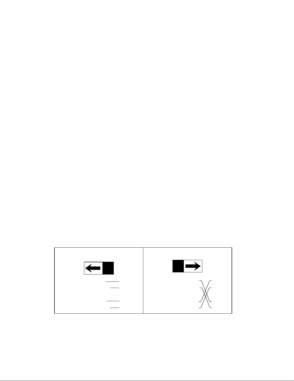
The UTP DCE/DTE switch is used to eliminate the need for crossover and custom cables
to connect devices together when using the RJ-45/48 port. Set this switch to DCE to use
a straight-through cable and to DTE when a crossover-cable would be required.
DCE
Twisted - 1 - RTIP TTIP
Pair - 2 - RRING TRING
Twisted - 4 - TTIP RTIP
Pair - 5 - TRING RRING
DTE
Twisted - 1 - RTIP TTIP
Pair - 2 - RRING TRING
Twisted - 4 - TTIP RTIP
Pair - 5 - TRING RRING
Page 4
T1/E1 Copper Line Configuration Settings:
The T1/E1 copper line codes and line lengths are configured using dip switches located
on the side of the Flex Point T1/E1 media converter.
Line Type Port Type Distances Switch Positions
1 2 3 4
T1 DSX-1 RJ-45/48 0’ – 133’ D D D D
T1 DSX-1 RJ-45/48 133’ – 266’ D D D U
T1 DSX-1 RJ-45/48 266’ – 399’ D D U D
T1 DSX-1 RJ-45/48 399’ – 533’ D D U U
T1 DSX-1 RJ-45/48 533’ – 655’ D U D D
T1 DS-1 RJ-45/48 0 dB D D D D
T1 DS-1 RJ-45/48 -7.5 dB D U D U
T1 DS-1 RJ-45/48 -15.0 dB D U U D
T1 DS-1 RJ-45/48 -22.5 dB D U U U
E1 75 ohm Coax/BNC Standard U D D D
E1 120 ohm RJ-45/48 Standard U D D U
E1 75 ohm Coax/BNC Extended U D U D
E1 120 ohm RJ-45/48 Extended U D U U
D = Down U = Up
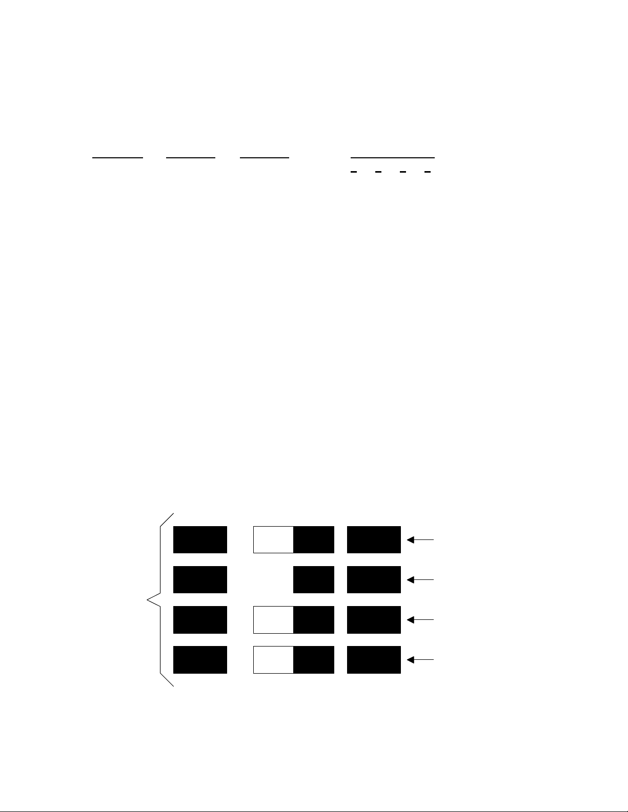
Operational Switch Settings and Functions:
The following operational switches located on the front of the Flex Point T1/E1 converter
are to assist in installation and fault isolation.
NORMAL
NORM
NORM
NORM
NORM
L/LB
R+L/LB
FO/1's
UTP/1's
Local Dual Loop Back
Remote & Local Loop Back
Force 1's to Fiber
Force 1's to Copper
Page 5
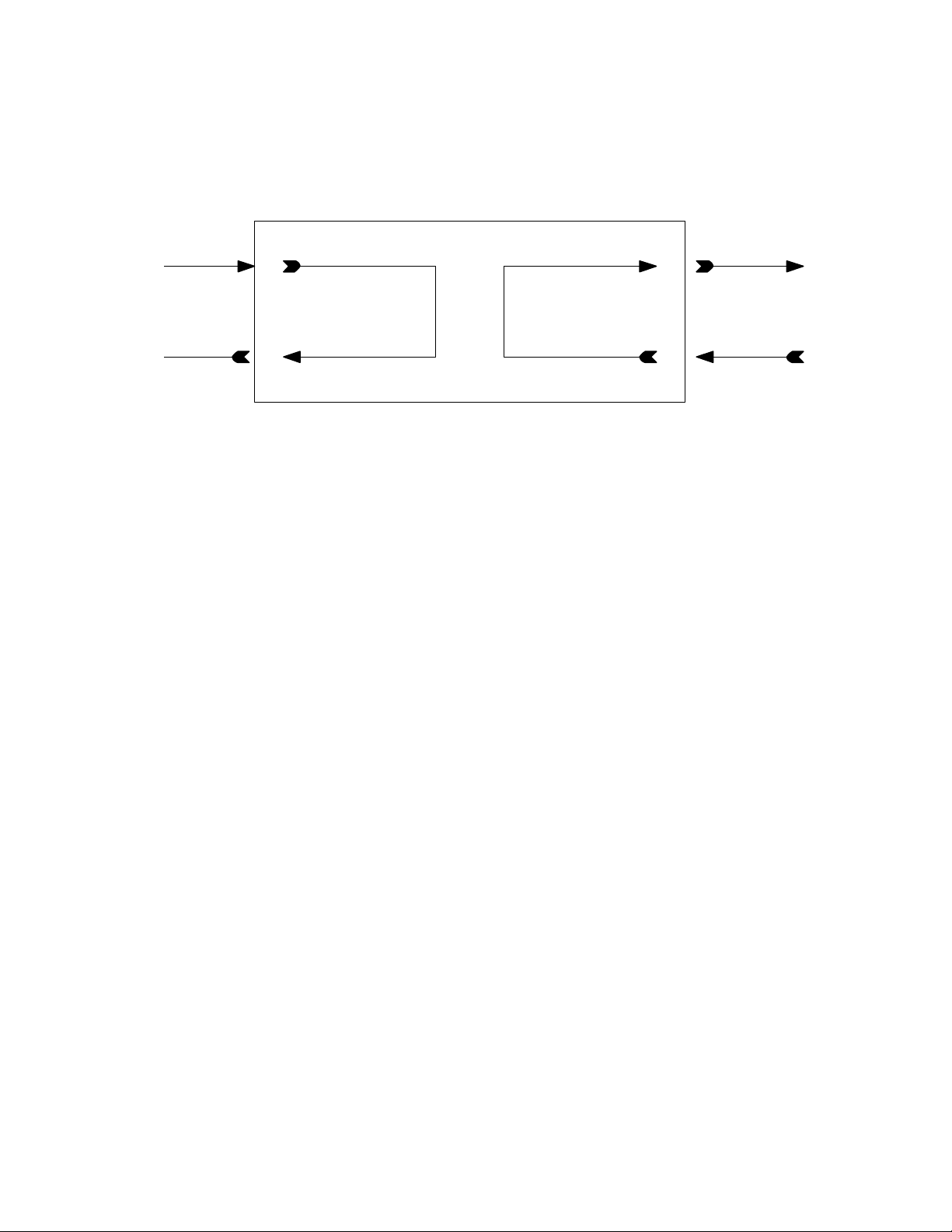
Local Loop-Back (L/LB)
This switch will set the Flex Point T1/E1 converter in a loop-back mode on both the fiber
and copper connections. By turning the switch to the normal position, the unit will
resume to normal operation.
CuRx
CuTx
Loopback Enabled
FO-Tx
FO-Rx
Transmit/force 1’s to Fiber
This switch is used to insert an “all ones” pattern into the data stream being transmitted
out of the fiber port on the Flex Point T1/E1 converter. Data being received on the coax
or twisted pair will be disabled and data being received on the fiber is passed through to
the coax or twisted pair side. By returning the switch to the normal position, the unit will
resume to normal operation.
Transmit/force 1’s to Coax or UTP
This switch is used to insert an “all ones” pattern into the data stream being transmitted
out of the coax or twisted pair on the Flex Point T1/E1 converter. Data being received on
the fiber will be disabled and data being received on the coax or twisted pair is passed
through to the fiber side. By returning the switch to the normal position, the unit will
resume to normal operation.
Page 6
Remote loop-back (R+L/LB)
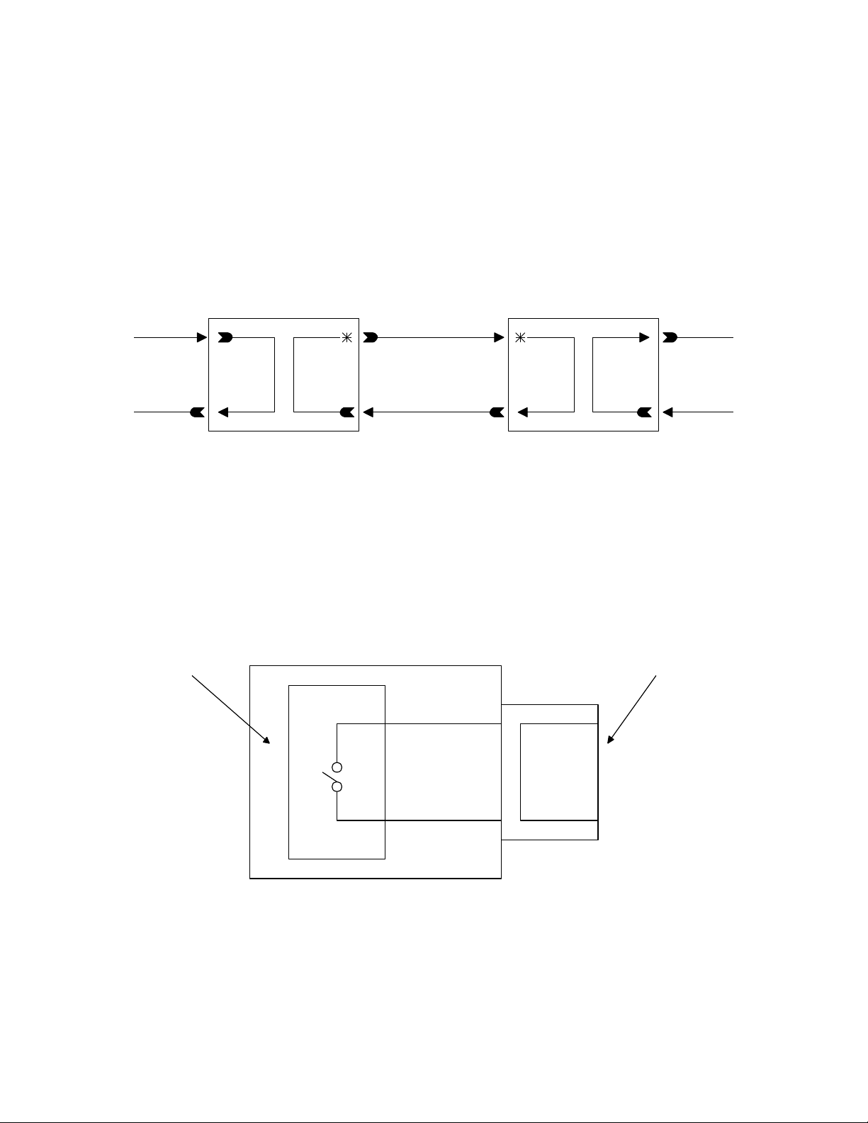
This switch will allow the entire fiber segment to be tested at either of the Flex Point
T1/E1 converters without having to set switches on both units. When set in this mode of
operation, the local unit is switched in a local loop-back mode. And in addition to the
local loop-back mode of operation, the fiber Tx port will be further encoded to carry a
remote loop-back protocol. This remote loop-back protocol will set the far end Flex
Point T1/E1 converter to remote loop-back mode of operation and return a signal to the
sending unit. An LED on the local and remote Flex Point T1/E1 converters will show a
configuration that the fiber segment is communicating properly between devices. By
returning the switch to the normal position, it will resume to normal operation.
CuRx
FoTx
CuTxFoRx
CuTx CuRx
Remote Loop Request
Over Fiber
FoRx FoTx
Alarm Relay Contacts
The Flex Point T1/E1 converter also features dry relay contacts for optionally connecting
the media converter into a separate T1/E1 alarm circuit. The relay closes when a loss of
power or when signal detect is lost to the copper or fiber connection.
RJ-45/RJ-48Relay
3
6
Operational rating on relay pins 3 & 6: 0 - 220 VDC max 2A
Page 7

LED Indicators:
LED Color Status Description
Power: Yellow On Power applied
Fiber: Green Off No Signal Detect
On Signal Detect
Blink All Ones received
UTP/Coax: Green Off No Signal Detect
On Signal Detect
Blink All Ones received
Test: Green Off Normal Operation
On L/LB or All 1’s Test Mode
Blink R+L/LB Received Master
Fast Blink R+L/LB Received Slave
Fiber Cable Specifications:
Multimode
Cable: 50/125, 62.5/125, 100/140 um
Wavelength: 1300 nm
Max Distance: 5km / 3.1 mi.
Singlemode:
Cable: 9/125um
Wavelength: 1300 nm
Max Distance: 28km / 16.8 mi.
Singlemode Long-haul
Cable: 9/125um
Wavelength: 1300nm
Max Distance: 58km / 36 mi.
Page 8

Copper Cable Specifications:
Twisted-Pair cable for T1
Gauge: 22 to 24 AWG
Impedance: 100 ohm +/- 10%
Impedance characteristic: 2.6 dB / 100m @ 1.0 MHz
Maximum Distance: 6,000 ft.
Twisted-Pair cable for E1
Gauge: 22 to 24 AWG
Impedance: 120 ohm +/- 10%
Impedance characteristic: 2.6 dB / 100m @ 1.0 MHz
Maximum Distance: 8,000 ft.
Coax cable for E1
Gauge: 22 to 24 AWG
Impedance: 75 ohm +/- 10%
Impedance characteristic: 2dB / 100m @ 1.0 MHz
Maximum Distance: 8,000 ft.
1000 Park Drive Lawrence, PA. 15055-1018
Phone: (724)746-5500 Fax: (724)746-0746
 Loading...