

Page 1

NOVEMBER 1997
MT632A-ST35
MT632A-ST232
MT632A-SM35
MT632A-SM232
SFOM-HS2
CUSTOMER SUPPORT INFORMATION
Order toll-free in the U.S. 24 hours, 7 A.M. Monday to midnight Friday: 877-877-BBOX
FREE technical support, 24 hours a day, 7 days a week: Call 724-746-5500 or fax 724-746-0746
Mail order: Black Box Corporation, 1000 Park Drive, Lawrence, PA 15055-1018
Web site: www.blackbox.com • E-mail: info@blackbox.com
SFOM-HS2
R
E
M
N
O
R
A
N
A
P
W
R
TS
T
C
D
TD
Page 2

1
TRADEMARKS
TRADEMARKS USED IN THIS MANUAL
UL is a registered trademark of Underwriters
Laboratories Incorporated.
ST is a registered trademark of AT&T.
Any other trademarks mentioned in this manual are
acknowledged to be the property of the trademark owners.
Page 3

2
SFOM-HS2
FEDERAL COMMUNICATIONS COMMISSION
AND
INDUSTRY CANADA
RADIO FREQUENCY INTERFERENCE STATEMENTS
This equipment generates, uses, and can radiate radio frequency energy
and if not installed and used properly, that is, in strict accordance with the
manufacturer’s instructions, may cause interference to radio communication. It has been tested and found to comply with the limits for a Class A
computing device in accordance with the specifications in Subpart J of
Part 15 of FCC rules, which are designed to provide reasonable protection
against such interference when the equipment is operated in a commercial
environment. Operation of this equipment in a residential area is likely
to cause interference, in which case the user at his own expense will be
required to take whatever measures may be necessary to correct the
interference.
Changes or modifications not expressly approved by the party responsible
for compliance could void the user’s authority to operate the equipment.
This digital apparatus does not exceed the Class A limits for radio noise emission
from digital apparatus set out in the Radio Interference Regulation of Industry
Canada.
Le présent appareil numérique n’émet pas de bruits radioélectriques dépassant les
limites applicables aux appareils numériques de classe A prescrites dans le Règlement
sur le brouillage radioélectrique publié par Industrie Canada.
Page 4

3
NOM STATEMENT
NORMAS OFICIALES MEXICANAS (NOM)
ELECTRICAL SAFETY STATEMENT
INSTRUCCIONES DE SEGURIDAD
1. Todas las instrucciones de seguridad y operación deberán ser leídas
antes de que el aparato eléctrico sea operado.
2. Las instrucciones de seguridad y operación deberán ser guardadas
para referencia futura.
3. Todas las advertencias en el aparato eléctrico y en sus instrucciones
de operación deben ser respetadas.
4. Todas las instrucciones de operación y uso deben ser seguidas.
5. El aparato eléctrico no deberá ser usado cerca del agua—por
ejemplo, cerca de la tina de baño, lavabo, sótano mojado o cerca de
una alberca, etc..
6. El aparato eléctrico debe ser usado únicamente con carritos o
pedestales que sean recomendados por el fabricante.
7. El aparato eléctrico debe ser montado a la pared o al techo sólo
como sea recomendado por el fabricante.
8. Servicio—El usuario no debe intentar dar servicio al equipo eléctrico
más allá a lo descrito en las instrucciones de operación. Todo otro
servicio deberá ser referido a personal de servicio calificado.
9. El aparato eléctrico debe ser situado de tal manera que su posición
no interfiera su uso. La colocación del aparato eléctrico sobre una
cama, sofá, alfombra o superficie similar puede bloquea la
ventilación, no se debe colocar en libreros o gabinetes que impidan
el flujo de aire por los orificios de ventilación.
Page 5

4
SFOM-HS2
10. El equipo eléctrico deber ser situado fuera del alcance de fuentes
de calor como radiadores, registros de calor, estufas u otros aparatos
(incluyendo amplificadores) que producen calor.
11. El aparato eléctrico deberá ser connectado a una fuente de poder
sólo del tipo descrito en el instructivo de operación, o como se
indique en el aparato.
12. Precaución debe ser tomada de tal manera que la tierra fisica y
la polarización del equipo no sea eliminada.
13. Los cables de la fuente de poder deben ser guiados de tal manera
que no sean pisados ni pellizcados por objetos colocados sobre o
contra ellos, poniendo particular atención a los contactos y
receptáculos donde salen del aparato.
14. El equipo eléctrico debe ser limpiado únicamente de acuerdo a las
recomendaciones del fabricante.
15. En caso de existir, una antena externa deberá ser localizada lejos
de las lineas de energia.
16. El cable de corriente deberá ser desconectado del cuando el equipo
no sea usado por un largo periodo de tiempo.
17. Cuidado debe ser tomado de tal manera que objectos liquidos no
sean derramados sobre la cubierta u orificios de ventilación.
18. Servicio por personal calificado deberá ser provisto cuando:
A: El cable de poder o el contacto ha sido dañado; u
B: Objectos han caído o líquido ha sido derramado dentro
del aparato; o
C: El aparato ha sido expuesto a la lluvia; o
D: El aparato parece no operar normalmente o muestra
un cambio en su desempeño; o
E: El aparato ha sido tirado o su cubierta ha sido dañada.
Page 6

5
UL LISTING REQUIREMENTS, EXIGENCES UL
UL Listing Requirements
IMPORTANT SAFETY INSTRUCTIONS
For North American Users
The SFOM-HS2 is powered by an external power supply
(product code PS632). To reduce the risk of shock, fire,
and injury, use it only with a UL
®
listed and CSA
Certified Class 2 power supply rated 9 VDC, 300 mA.
Exigences UL
INSTRUCTIONS IMPORTANTS DE SÉCURITÉ
Pour les utilisateurs Nord Americains
Le SFOM-HS2 est renforcé par un transformateur
extérieur (code produit PS632). Afin de réduire le risque
d’électrocution, d’incendie ou de blessure, utiliser
seulement avec un transformateur 9 VDC, 300 mA
Certifié classe 2 CSA et repris sur la liste UL
®
.
Page 7

6
SFOM-HS2
TÜV Certification Requirements
Installation – User Instructions
Electrical ratings: 9 VDC, 300 mA
The following instructions are intended to guarantee the
basic operation of the equipment concerning safety.
CAUTION!
1. To reduce the risk of electric shock, use only with a
power supply which is approved for the lastest
version of EN 60950.
2. For continuous protection against risk of fire, do not
operate the equipment with the enclosure completely
or partially removed.
3. Do not install the equipment with indicators facing down.
TÜV-Zertifizierungsanforderungen
Installation – Bedieningsanleitung
Leistungsaufnahme: 9 VDC, 300 mA
Die nachfolgenden Anleitungen sollen den Grundbetrieb
der Anlage hinsichtlich Sicherheit gewährleisten.
ACHTUNG!
1. Um das Risiko eines elektrischenSchlages oder
Brandes so weit wie möglich zu vermeiden verwenden
Sie nur ein Netzteil, das gemäß der neuesten Version
des Standards EN 60950 zugelassen ist.
2. Als ständigen Schutz vor Brand betrieben Sie die Anlage
nie mit ganz oder teilweise entfernter Abdeckung.
3. Installieren Sie de Anlage nicht mit nach unten
weisenden Anzeigeelementen.
Page 8

7
TABLE OF CONTENTS
Contents
1. Specifications ..................................................... 9
2. Introduction ..................................................... 13
3. Installation and Configuration ....................... 16
4. Operation ......................................................... 19
4. Troubleshooting .............................................. 23
4.1 Diagnostic Loopback Tests ...................... 23
4.2 Calling Black Box ..................................... 25
4.3 Shipping and Packaging ........................ 26
Page 9

8
SFOM-HS2
1. Specifications
Compliance — FCC Class B, IC Class/
classe B; UL®, CSA, TÜV
Interfaces — Device side:
“–Sx232” models:
TIA RS-232/ITU-TSS V.24;
“–Sx35” models:
ITU-TSS V.35;
Line side:
Multimode fiberoptic
Protocols —
Synchronous or asynchronous
(user-selectable)
Clock Source — Internal, external (from
device side), or recovered
(from line-side receive
signal)
Data Format — Async: 1 start bit (fixed); 5, 6,
7, or 8 data bits; even, odd,
or no parity; and 1, 1.5, or
2 stop bits (user-selectable),
with a minimum of 8 and a
maximum of 11 total bits
Page 10

9
CHAPTER 1: Specifications
Frequency Allowance — Async: Stop bit can be
shortened on the receive
end to accommodate a
frequency difference
between the SFOM-HS2
and the attached device,
either by 12.5% (allows a
–2.5% to +1% difference)
or by 25% (allows a –2.5%
to +2.3% difference), userselectable
Carrier — Constantly ON or follows
RTS (user-selectable)
Operation — Full-duplex over duplex
fiberoptic cable
Data Rates —
56 or 64 Kbps (user selectable)
Optical Output
(Transmit Level)— 100/140µ fiber: –26 dBm;
62.5/125µ fiber: –28 dBm;
50/125µ fiber: –32 dBm
Receiver Sensitivity — –43 dBm
Page 11

10
SFOM-HS2
Optical Wavelength — 850 nm
Maximum Distance — 2.5 miles (4 km)
User Controls — (1) Top-mounted three-
position slide switch for
test selection;
(10) Internal DIP-switch
positions for protocol, data
rate, data format, stop-bit
shortening, carrier, and
interface-based loop control
Diagnostics — Local analog and remote
digital loopback, controlled
with top-panel switch or
optionally with interface
signals
Indicators — (4) Top-mounted LEDs:
PWR (power), TST (test),
CD, and TD
Page 12

11
CHAPTER 1: Specifications
Connectors — Device side: (1) Front-
mounted DB25 female;
V.35 models include a
17.5" (45-cm) adapter cable
that patches this to an M/34
(34-pin M-block) female;
Line side:
“-SMxxx” models:
(2) SMA 906 female;
“-STxxx” models:
(2) ST female
Power — From wallmount power
supply PS632 (not included):
Input: 115-VAC, 60 Hz;
Output: 9 VDC, 300 mA
Size — 5.1"H x 2.1"W x 1.2"D
(13 x 5.3 x 3 cm)
Weight — 0.2 lb. (0.1 kg)
Page 13
12
SFOM-HS2
2. Introduction
The SFOM-HS2 is a high-speed fiberoptic local
(short-haul) modem. You can use pairs of SFOMHS2s to make extended-distance, full-duplex
connections across fiberoptic cable between
synchronous or asynchronous terminals, PCs, or
controllers on one end and high-speed computers
on the other.
There are four models of SFOM-HS2 available (see
Table 2-1 below). Each has fiberoptic connectors on
one side for attaching fiberoptic cable, and a DB25
connector on the other side for attaching your
data-terminal equipment (DTE). (The V.35 models
include a special adapter cable that patches the
DB25 connector to a 34-pin M-block connector
more appropriate for most V.35 equipment.)
Table 2-1. The SFOM-HS2 Models and their Interfaces
Product Code Fiber Connectors DTE Interface Standard
MT632A-ST35 ST®Style V.35
MT632A-ST232 ST Style RS-232
MT632A-SM35 SMA Style V.35
MT632A-SM232 SMA Style RS-232
Page 14

13
CHAPTER 2: Introduction
Each SFOM-HS2 converts the electrical data signal
from the DTE interface into light pulses for transmission across the fiber interface. It can operate
at 56 or 64 Kbps, and can transmit data as far as
2.5 miles (4 km); see Figure 2-1 below.
Figure 2-1. A typical SFOM-HS2 application.
Each unit also supports two ITU V.54 industrystandard loop tests for easy, convenient diagnostics
(see Section 4.3).
The SFOM-HS2 can get its transmit timing from
any of three sources: its own oscillator (internal
clock), the attached DTE (external clock), or
the receive signal (recovered clock).
Mainframe
Controller
Up to 2.5 miles
(4 km)
Duplex Fiberoptic Cable
SFOM-HS2
SFOM-HS2
Page 15

14
SFOM-HS2
You can also choose whether carrier is constantly
ON or switched. In switched mode, the carrier is
controlled by the RTS signal so you can transfer
a control signal end-to-end.
9-VDC power for the unit comes from the external
wallmout AC power supply PS632 (sold separately).
Page 16

15
CHAPTER 3: Installation and Configuration
3. Installation and Configuration
Each SFOM-HS2 has a three-position loop-activation
switch on the front panel, plus ten internal DIP
switches (see Figure 3-1 below). Use these switches
to configure the SFOM-HS2 prior to installation.
(See Chapter 4 for more about configuration options.)
Figure 3-1. The internal DIP switches.
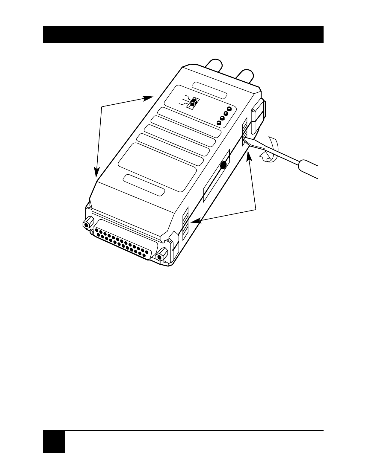
To set the DIP switches in an SFOM-HS2:
1. Use a small screwdriver to gently pry open each
of the unit’s four locking tabs and open the
plastic case (see Figure 3-2 on the next page).
ON ON
1
ON
23456
7
8
9
10
Number of Bits (async)
Stop Bit (async)
Data Rate
Transmit Timing
Carrier
Loop Control
Page 17
16
SFOM-HS2
Figure 3-2. Opening the plastic cover.
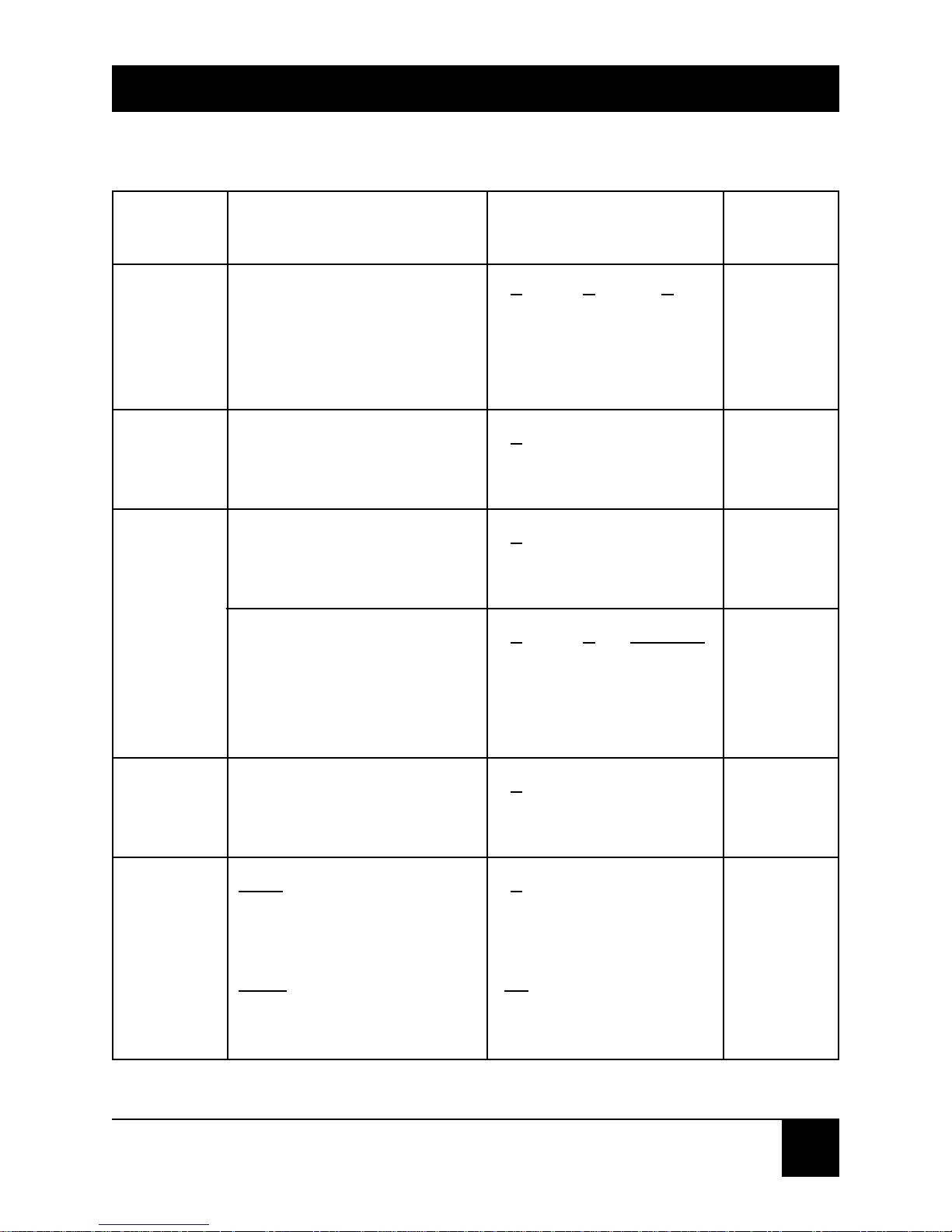
2. Set the DIP switches to match your
application’s requirements. Table 3-1 on the
next page lists the possible settings. (A similar
table is printed inside the unit’s plastic case,
for reference during field installations.) See
pages 18 and 19 for the recommended settings
for most synchronous and asynchronous
applications respectively.
R
EM
N
O
R
ANA
PW
R
TST
CD
TD
Locking
Tabs
Locking
Tabs
Page 18
17
CHAPTER 3: Installation and Configuration
Transmit
Timing
Data
Rate
Async
Data
Format
(Word
Length)
Carrier
Loop
Activation
from the
DTE
Interface
(Loop
Control)
Determines sync clock
source or async mode
Determines datatransmission rate
Determines the amount
of stop-bit shortening to
be used in async mode
Determines word length
in async mode (see
Appendix A)
Determines carrier—
constantly on, or
controlled by RTS
ANA
Determines DTE control
of analog loop
REM
Determines DTE control
of remote digital loop
1
2 3
ON OFF OFF
OFF OFF OFF
OFF OFF ON
OFF ON OFF
4
ON—56 Kbps
OFF—64 Kbps
5
ON—12.5%
OFF—25%
6
7 # of bits
OFF OFF 8
OFF ON 9
ON OFF 10
ON ON 11
8
ON—Constantly ON
OFF—Controlled
9
ON—Enable
OFF—Disable
10
ON—Enable
OFF—Disable
External
Internal
Receive
Async
64 Kbps
25%
10 bits
ON
Disable
Disable
Feature Function Possible DIP Switch Default
Settings Settings
Table 3-1. DIP-Switch Functions, Settings, and Defaults
Page 19

18
SFOM-HS2
• Follow these steps to configure your
SFOM-HS2 for synchronous operation.
(Note that DIP switches 5, 6, and 7 are
not relevant for sync operation.)
a. Use switches 1, 2, and 3 to set XMT timing
to INT (internal), EXT (external), or RCV
(recovered).
b. Use switch 4 to set the data rate
to 56 or 64 Kbps.
c. Use switch 8 to set carrier to constantly
on or controlled by RTS.
For example, DIP switch settings on an
SFOM-HS2 configured for internal clocking,
64 Kbps, and constant carrier would be:
1, 2, 3 = OFF 4 = OFF 8 = ON
Page 20

19
CHAPTER 3: Installation and Configuration
•Follow these steps to configure your
SFOM-HS2 for for asynchronous operation.
a. Use switches 1, 2, and 3 to select “async”
(turn XMT timing off).
b. Use switch 4 to set the data rate.
c. Use switches 5, 6, and 7 to set frequency
allowance and character length (if necessary,
refer to Table 3-1 on page 17, Figure 3-1 on
page 15).
d. Use switch 8 to set carrier to constantly
on or controlled by RTS.
For example, DIP-switch settings on an SFOMHS2 configured for async operation, 64 Kbps,
and constant carrier would be:
1, 3 = OFF 2 = ON 4 = ON
6, 7 = OFF 8 = ON
NOTE
PCs working at high speeds in async mode operate at
57.6 Kbps (instead of 56 Kbps). In such cases, the PC
should be set to use two stop bits, and the SFOM-HS2
should be set to use one stop bit and to communicate
at 56 Kbps.
Page 21

20
SFOM-HS2
3. Carefully close the two halves of the unit’s
plastic case, pressing them together firmly
until the four locking tabs snap back into place.
4. If possible, plug the SFOM-HS2 directly into
your DTE’s DB25 connector (or, if your unit is
a V.35 model, run the included adapter cable
from the SFOM-HS2 to your DTE’s
M/34 [also
called “34-pin M-block”] connector).
If you have
to run an additional cable between the DTE
and the SFOM-HS2, keep it as short as possible.
Once you’ve made this connection, tighten the
connector screws to ensure a secure hold.
5. Remove the plastic dust caps from the
fiberoptic connectors and attach your
fiber cable to them:
• Connect the local SFOM-HS2’s TX port
to the remote unit’s RX port.
• Connect the local SFOM-HS2’s RX port
to the remote unit’s TX port.
Page 22

21
CHAPTER 3: Installation and Configuration
6. Connect the output cord of the included
external power supply to the SFOM-HS2’s
power jack, then plug the transformer into
a nearby AC wall outlet.
Page 23

22
SFOM-HS2
4. Troub leshooting
4.1 Diagnostic Loopback Tests
You can configure the SFOM-HS2 to perform either
of two test loops. V.54 Loop 3 (ANA, local analog
loopback) tests the local SFOM-HS2 by routing the
transmit signal the unit gets from the attached device
back to that device through its receiver (see Figure 4-1
below).
Figure 4-1. Local analog loopback (ANA).
V.54 Loop 2 (REM, remote digital loopback) tests
the local SFOM-HS2, the line, and the remote
SFOM-HS2 (see Figure 4-2 below).
Figure 4-2. Remote digital loopback (REM).
Page 24

23
CHAPTER 4: Troubleshooting
Both loops can be controlled either physically, with
the top-panel loop-selection switch, or electronically,
by having the DTE raise and lower the signals to
Pins 18 (ANA) and 21 (REM) of the SFOM-HS2’s
DB25 connector.
NOTE
To select loops electronically with the V.35 version of
the SFOM-HS2, use Pins JJ (ANA) and HH (REM) of the
adapter cable’s M/34 connector.
To activate loops from your DTE, DIP switches 9 and
10 must be set to ENABLE (see Figure 3-1 on page 15
and Table 3-1 on page 17).
Start the loop test by moving the top-panel loop-
selection switch to the desired test position or
raising
the appropriate signal on the DTE interface.
While a diagnostic loop is active, the top-panel
TST
LED will light and the Test Mode signal (DB25 Pin 25
or M/34 Pin KK)
will be held high (ON).
To return to normal operation, reset the top-panel
loop-selection switch to the center NOR position
or lower the controlling DTE-interface signal.
The TST LED and Test Mode signal will turn
OFF automatically.
Page 25

24
SFOM-HS2
4.2 Calling Black Box
If your SFOM-HS2 seems to be malfunctioning, do
not attempt to alter or repair the unit. It contains no user-
serviceable parts. Call Black Box Technical Support
at 724-746-5500. The problem might be solvable over
the phone.
Before you call, make a record of the history of the
problem. We will be able to provide more efficient
and accurate assistance if you have a complete
description, including:
• the nature and duration of the problem.
• when the problem occurs.
• the components involved in the problem.
• any particular application that, when used,
appears to create the problem or make it worse.
Page 26

25
CHAPTER 4: Troubleshooting
4.3 Shipping and Packaging
If you need to transport or ship your SFOM-HS2:
• Package it carefully. We recommend
that you use the original container.
• If the shipping is return- or repair-related,
pack the SFOM-HS2, its power supply, and
this manual together. Contact Black Box
to get a Return Materials Authorization
(RMA) number.
Page 27

NOTES
 Loading...