

Page 1
CUSTOMER
SUPPORT
INFORMATION
Order toll-free in the U.S. 24 hours, 7 A.M. Monday to midnight Friday: 877-877-BBOX
FREE technical support, 24 hours a day, 7 days a week: Call 724-746-5500 or fax 724-746-0746
Mail order: Black Box Corporation, 1000 Park Drive, Lawrence, PA 15055-1018
Web site: www.blackbox.com • E-mail: info@blackbox.com
JUNE 1998
MT610A-ST MT611A-ST
MT610A-SM MT611A-SM
MT610AE-ST MT611AE-ST
MT610AE-SM MT611AE-SM
MT613AE-FC
MT613A-ST-D48
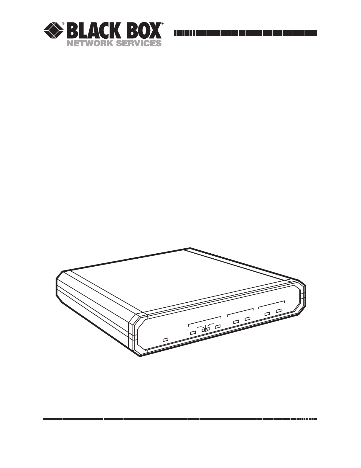
T1/E1 Fiberoptic Line Driver
(T1/E1 FOLD)
OPTICAL
AIS
AIS
ERR
LOW
ELECTRICAL
TEST
NORM
REM
LOC
PWR
T1 Fiber Optic Line Driver
Page 2

1
T1/E1 FIBEROPTIC LINE DRIVER
FEDERAL COMMUNICATIONS COMMISSION
AND
INDUSTRY CANADA
RADIO FREQUENCY INTERFERENCE STATEMENTS
This equipment generates, uses, and can radiate radio frequency energy and if not
installed and used properly, that is, in strict accordance with the manufacturer’s
instructions, may cause interference to radio communication. It has been tested
and found to comply with the limits for a Class A computing device in accordance
with the specifications in Subpart J of Part 15 of FCC rules, which are designed to
provide reasonable protection against such interference when the equipment is
operated in a commercial environment. Operation of this equipment in a
residential area is likely to cause interference, in which case the user at his own
expense will be required to take whatever measures may be necessary to correct
the interference.
Changes or modifications not expressly approved by the party responsible for
compliance could void the user’s authority to operate the equipment.
This digital apparatus does not exceed the Class A limits for radio noise emission from
digital apparatus set out in the Radio Interference Regulation of Industry Canada.
Le présent appareil numérique n’émet pas de bruits radioélectriques dépassant les limites
applicables aux appareils numériques de la classe A prescrites dans le Règlement sur le
brouillage radioélectrique publié par Industrie Canada.
Page 3

2
T1/E1 FIBEROPTIC LINE DRIVER
NORMAS OFICIALES MEXICANAS (NOM)
ELECTRICAL SAFETY STATEMENT
INSTRUCCIONES DE SEGURIDAD
1. Todas las instrucciones de seguridad y operación deberán ser leídas antes
de que el aparato eléctrico sea operado.
2. Las instrucciones de seguridad y operación deberán ser guardadas para
referencia futura.
3. Todas las advertencias en el aparato eléctrico y en sus instrucciones de
operación deben ser respetadas.
4. Todas las instrucciones de operación y uso deben ser seguidas.
5. El aparato eléctrico no deberá ser usado cerca del agua—por ejemplo, cerca
de la tina de baño, lavabo, sótano mojado o cerca de una alberca, etc..
6. El aparato eléctrico debe ser usado únicamente con carritos o pedestales que
sean recomendados por el fabricante.
7. El aparato eléctrico debe ser montado a la pared o al techo sólo como sea
recomendado por el fabricante.
8. Servicio—El usuario no debe intentar dar servicio al equipo eléctrico más allá
a lo descrito en las instrucciones de operación. Todo otro servicio deberá ser
referido a personal de servicio calificado.
9. El aparato eléctrico debe ser situado de tal manera que su posición no
interfiera su uso. La colocación del aparato eléctrico sobre una cama, sofá,
alfombra o superficie similar puede bloquea la ventilación, no se debe colocar
en libreros o gabinetes que impidan el flujo de aire por los orificios de
ventilación.
10. El equipo eléctrico deber ser situado fuera del alcance de fuentes de calor
como radiadores, registros de calor, estufas u otros aparatos (incluyendo
amplificadores) que producen calor.
Page 4

3
T1/E1 FIBEROPTIC LINE DRIVER
11. El aparato eléctrico deberá ser connectado a una fuente de poder sólo del
tipo descrito en el instructivo de operación, o como se indique en el aparato.
12. Precaución debe ser tomada de tal manera que la tierra fisica y la polarización
del equipo no sea eliminada.
13. Los cables de la fuente de poder deben ser guiados de tal manera que no
sean pisados ni pellizcados por objetos colocados sobre o contra ellos,
poniendo particular atención a los contactos y receptáculos donde salen
del aparato.
14. El equipo eléctrico debe ser limpiado únicamente de acuerdo a las
recomendaciones del fabricante.
15. En caso de existir, una antena externa deberá ser localizada lejos de las lineas
de energia.
16. El cable de corriente deberá ser desconectado del cuando el equipo no sea
usado por un largo periodo de tiempo.
17. Cuidado debe ser tomado de tal manera que objectos liquidos no sean
derramados sobre la cubierta u orificios de ventilación.
18. Servicio por personal calificado deberá ser provisto cuando:
A: El cable de poder o el contacto ha sido dañado; u
B: Objectos han caído o líquido ha sido derramado dentro del aparato; o
C: El aparato ha sido expuesto a la lluvia; o
D: El aparato parece no operar normalmente o muestra un cambio en su
desempeño; o
E: El aparato ha sido tirado o su cubierta ha sido dañada.
Page 5

4
T1/E1 FIBEROPTIC LINE DRIVER
CONTENTS
1. Specifications . . . . . . . . . . . . . . . . . . . . . . . . . . . . . . . . . . . . . . . . . . . . . 6
2. Introduction . . . . . . . . . . . . . . . . . . . . . . . . . . . . . . . . . . . . . . . . . . . . . . 8
2.1 Functional Description. . . . . . . . . . . . . . . . . . . . . . . . . . . . . . . . . . . 8
2.2 System Considerations . . . . . . . . . . . . . . . . . . . . . . . . . . . . . . . . . . . 9
2.2.1 Data Transfer . . . . . . . . . . . . . . . . . . . . . . . . . . . . . . . . . . . . . . 9
2.2.2 Interfacing . . . . . . . . . . . . . . . . . . . . . . . . . . . . . . . . . . . . . . . . 9
2.2.3 T1 Interface . . . . . . . . . . . . . . . . . . . . . . . . . . . . . . . . . . . . . . . 10
2.2.4 E1 Interface . . . . . . . . . . . . . . . . . . . . . . . . . . . . . . . . . . . . . . . 10
3. Installation . . . . . . . . . . . . . . . . . . . . . . . . . . . . . . . . . . . . . . . . . . . . . . . 11
3.1 General . . . . . . . . . . . . . . . . . . . . . . . . . . . . . . . . . . . . . . . . . . . . . . . 11
3.2 What’s Included in the Package . . . . . . . . . . . . . . . . . . . . . . . . . . . 11
3.3 Site Requirements. . . . . . . . . . . . . . . . . . . . . . . . . . . . . . . . . . . . . . . 11
3.4 Setting the Switches . . . . . . . . . . . . . . . . . . . . . . . . . . . . . . . . . . . . . 12
3.4.1 Internal Switch Settings Information. . . . . . . . . . . . . . . . . . . 12
3.4.2 Interface Jumper . . . . . . . . . . . . . . . . . . . . . . . . . . . . . . . . . . . 12
3.4.3 Interface Grounding . . . . . . . . . . . . . . . . . . . . . . . . . . . . . . . . 13
3.4.4 Range . . . . . . . . . . . . . . . . . . . . . . . . . . . . . . . . . . . . . . . . . . . . 13
3.4.5 Optical Signaling . . . . . . . . . . . . . . . . . . . . . . . . . . . . . . . . . . . 14
3.4.6 Electrical/Chassis Grounding. . . . . . . . . . . . . . . . . . . . . . . . . 14
3.5 Installation in 19” Racks . . . . . . . . . . . . . . . . . . . . . . . . . . . . . . . . . . 16
3.5.1 Installation of a Single Unit . . . . . . . . . . . . . . . . . . . . . . . . . . 16
3.5.2 Installation of Two Units. . . . . . . . . . . . . . . . . . . . . . . . . . . . . 17
3.6 Preparation for Operation . . . . . . . . . . . . . . . . . . . . . . . . . . . . . . . . 19
3.6.1 Grounding . . . . . . . . . . . . . . . . . . . . . . . . . . . . . . . . . . . . . . . . 19
3.6.2 Power Connection . . . . . . . . . . . . . . . . . . . . . . . . . . . . . . . . . . 19
3.6.3 Fiberoptics Connection. . . . . . . . . . . . . . . . . . . . . . . . . . . . . . 21
3.6.4 E1/T1 Cable Connection . . . . . . . . . . . . . . . . . . . . . . . . . . . . 21
4. Operation . . . . . . . . . . . . . . . . . . . . . . . . . . . . . . . . . . . . . . . . . . . . . . . . 22
4.1 Front Panel Indicators . . . . . . . . . . . . . . . . . . . . . . . . . . . . . . . . . . . 22
4.2 Preparation for Operation, General . . . . . . . . . . . . . . . . . . . . . . . . 22
4.3 Operation Instructions . . . . . . . . . . . . . . . . . . . . . . . . . . . . . . . . . . . 23
5. Troubleshooting . . . . . . . . . . . . . . . . . . . . . . . . . . . . . . . . . . . . . . . . . . . 24
Page 6

5
T1/E1 FIBEROPTIC LINE DRIVER
Appendix A: Functional Interface Specifications . . . . . . . . . . . . . . . . . . 25
Appendix B: DC Power-Supply Connection. . . . . . . . . . . . . . . . . . . . . . . 26
Page 7

6
T1/E1 FIBEROPTIC LINE DRIVER
1. Specifications
Compliance — All models: FCC Class A, IC Class/classe A;
230-VAC (“-AE” suffix) models: CE
Interfaces — Device side:
All models: Either 100-Ω balanced (4-wire) T1, 100-Ω
balanced (4-wire) E1; or 75-Ω unbalanced (coaxial) E1
(user-selectable);
Line side:
MT610 models: Multimode fiberoptic, 1300 nm;
MT611 models: Multimode fiberoptic, 850 nm;
MT613 models: Single-mode fiberoptic, 1300 nm
Data Rate — T1: 1.544 Mbps;
E1: 2.048 Mbps
Receiver
Sensitivity — For BER=10
-9
: –38 dBm at 850 nm or –40 dBm at 1300 nm
User Controls — All internal:
(5) DIP switches for transmission range, grounding, and
signal-loss handling;
(1) Slide switch for interface
Diagnostic — Dry-contact-closure alarm on DB15 Pins 6 and 13 for signal
or power loss; minimum switching current 1 amp
Indicators — (2) Front-mounted LEDs: Power and Signal Loss
Page 8

7
T1/E1 FIBEROPTIC LINE DRIVER
Connectors — All rear-mounted:
“-SM” models: (2) SMA female;
“-ST” models: (2) ST female;
“-FC” models: (2) FC female;
All models:
(1) DB15 for balanced T1 or E1 I/O;
(2) BNC female for unbalanced E1 I/O
Maximum
Altitude — 10,000 ft. (3048 m)
Temperature
Tolerance — 32 to 122˚F (0 to 50˚C)
Humidity
Tolerance — 0 to 90% noncondensing
Enclosure — Steel
Power — MT610-13A-xx: From internal power supply with cord:
103.5 to 126.5 VAC, 47 to 63 Hz;
MT610-13AE-xx: From internal power supply with cord:
207 to 253 VAC, 47 to 63 Hz;
MT610-13A-D48: From internal power supply with cord:
–42 to –57 VDC at 60 mA;
Consumption: 5 watts maximum
Size — 1.8" (1U) H x 7"W x 8.1"D (4.5 x 17.9 x 20.3 cm)
Weight — 3 lb. (1.1 kg)
Page 9

8
T1/E1 FIBEROPTIC LINE DRIVER
2. Introduction
2.1 Functional Description
The T1/E1 Fiberoptic Line Driver is used for transmission of T1 (1.544 Mbps) and
E1 (2.048 Mbps) data over multi-mode or single-mode fiberoptic media. The Line
Driver is transparent to T1 and E1 framing, and can transmit data using any
framing pattern with AMI, HDB3 or B8ZS coded signals.
The Line Driver converts the T1/E1 electrical signal into an optical signal using
an infrared LED transmitter. At the opposite end of the fiber, the optical signal is
converted back into an electrical signal and amplified to the required level.
Automatic Gain Control (AGC) circuits are used to accommodate various
distances. The Line Driver uses a Phase Locked Loop (PLL) circuit to recover data
and clock from the signal. The Line Driver provides three user-selectable electrical
interface options:
• T1—for 100 terminated balanced signals
• E1—for 120 terminated balanced signals
• E1—for 75 terminated unbalanced signals
Both a 15-pin connector and coaxial connectors are provided on the rear panel.
Internal jumpers enable the input/output ports to be grounded or floating,
according to the application.
Diagnostic and alarm features include an LED status indicator, all
“
ones”
signaling (AIS) alarm generation, and dry contact closure upon link failure.
The Line Driver is designed to operate with several different grades and sizes
of fiberoptic cable, and provides the user with:
• Immunity to electrical interference such as EMI, RFI, spikes and differential
ground loops.
• Protection from sparking and lightning.
• A secure link in hazardous or hostile environments.
The standard version is supplied with an 850-nm multi-mode fiberoptic
interface. A 1300 nm single- or multi-mode interface is also available.
Page 10

9
T1/E1 FIBEROPTIC LINE DRIVER
The electrical interface meets requirements of AT&T PUB 62411 and CCITT
G.703 for a T1 interface, and CCITT G.823 for an E1 interface. The Line Driver
operates from either 100 VAC, 115 VAC, 230 VAC, or - 48 VDC. The unit comes
in a compact standalone case that can be placed on a desktop or shelf, or can be
mounted in a 19-inch rack (with adapters).
2.2 System Considerations
The Line Driver provides a simple and reliable means for transmitting full-duplex
T1 or E1 signals via a fiberoptic medium.
Figure 2-1. Typical Line Driver Application.
2.2.1 D
ATATRANSFER
In the application illustrated in Figure 2-1, each Line Driver receives T1 or E1
signals which are equalized to overcome electrical link distortion. The Line Driver
then converts the T1 or E1 signals into an optical signal. The optical signal is
coupled to the fiberoptic media and transmitted via the optical link to the remote
unit. The optical output power is user-selectable by a two-position switch marked
Range. Its setting depends on the fiberoptic link. A high-sensitivity pre-amplifier
and an AGC (Automatic Gain Control) circuit enable the remote unit to receive
the optical signal. The output of the receiver is applied to the clock-recovery and
data-regeneration circuit which then applies it to the electrical interface driving
circuit.
2.2.2 I
NTERFACING
The electrical interface is selectable by means of a three-position internal
INTERFACE switch.
T1/E1
Fiberoptic
Line Driver
T1/E1
Fiberoptic
Line Driver
Twisted
Pair or
Coax
Twisted
Pair or
Coax
T1 or E1
Mux
T1 or E1
Fiberoptic
Cable
T1 or E1
T1 or E1
Mux
Page 11

10
T1/E1 FIBEROPTIC LINE DRIVER
2.2.3 T1 I
NTERFACE
The T1 interface fully complies with requirements of AT&T PUB 62411 and G.703.
Two types of line coding can be used: AMI or B8ZS. Select the T1 interface by
setting the INTERFACE switch to the left position.
2.2.4 E1 I
NTERFACE
The Line Driver’s E1 interface fully complies with the applicable CCITT
recommendations (pulse mark and HDB-3 line coding per CCITT Rec. G.823).
Select the E1 interface by setting the INTERFACE switch to the middle position
for balanced signals or to the right position for unbalanced signals.
Page 12

11
T1/E1 FIBEROPTIC LINE DRIVER
3. Installation
3.1 General
The Line Driver is a standalone unit. Special hardware for mounting the unit
in a 19-inch rack can be ordered separately (request part number RM523). This
hardware lets you install either a single unit or two units side-by-side using minimal
rack space of 1U (1.72”) in height.
This chapter provides mechanical and electrical installation procedures for the
Line Driver. Before installing the unit, refer to Sections 3.4 and 3.5 for internal
switch setting procedures and additional information.
If you encounter a problem, refer to Chapter 5 for troubleshooting instructions.
3.2 What’s Included in the Package
1. After unpacking the Line Driver, inspect the unit for damage. If you notice
damage, call Black Box immediately. The package contains the following:
• Line Driver
• Power cord
• This user’s manual
2. Place the Line Driver securely on a clean surface.
3.3 Site Requirements
Install the Line Driver within 5 feet (1.5 m) of a grounded AC outlet capable
of furnishing the rated voltage of the unit (100, 115, 230 VAC or - 48 VDC).
The ambient operating temperature of the T1/E1 FOLD should be 32 to 122 °F
(0 to 50°C) at a relative humidity of up to 90%, non-condensing.
Page 13

12
T1/E1 FIBEROPTIC LINE DRIVER
3.4 Setting the Switches
WARNING
Disconnect the unit from the power line before removing cover.
HIGH VOLTAGE—Any adjustment, maintenance, and repair of the
opened instrument under voltage should be avoided as much as
possible and should be carried out only by a skilled person who is
aware of the hazard involved.
Capacitors inside the instrument may still be charged even after the
instrument has been disconnected from its source of supply.
To change the switch settings, follow these steps:
1. Disconnect the power cable from the mains outlet.
2. Gain access to the Line Driver interior. Release the two rear panel screws
and use them as levers to pull out the interior of the unit as a drawer.
3. Identify the switches, according to Figure 3-1.
4. Install the switches in the desired positions (refer to Section 3.5).
5. Reinstall the Line Driver drawer.
3.4.1 I
NTERNALSWITCHSETTINGSINFORMATION
Before installing the Line Driver, set the internal switches according to your
application (that is, electrical interface and optical link characteristics). The
switches are located on the Line Driver board, as shown in Figure 3-1. Switch
functions are also listed in Table 3-2.
3.4.2 I
NTERFACEJUMPER
The interface jumper (item 4 in Figure 3-1) selects one of three interface options:
• 100 (for T1 balanced signals, usually applied by the DB15 connector).
• 120 (for E1 balanced signals, usually applied by the DB15 connector).
• 75 (for E1 unbalanced signals, usually applied by the two BNC connectors).
Page 14

13
T1/E1 FIBEROPTIC LINE DRIVER
3.4.3 I
NTERFACEGROUNDING
Both Input and Output can be individually grounded by means of two 2-position
GROUNDED/FLOATING switches (items 2 and 3 in Figure 3-1).
3.4.4 R
ANGE
RANGE (item 1 in Figure 3-1) selects the optical output power coupled to the
fiber, depending on the fiber core diameter. Table 3-1 summarizes the optional
output power available at the transmitter as a function of the wavelength and the
type of fiber used.
Figure 3-1. Location of Switches and Jumpers.
FLOATING
GROUNDED
INPUT
2
FLOATING
GROUNDED
OUTPUT
3
SHORT
LONG
RANGE
1
ON
OFF
OPTICAL
AIS XMT
5
6
NC
100 Ohm
BAL
T1
INTERFACE
4
120 Ohm
BAL
E1
75 Ohm
UNBAL
E1
CEPT (E1)
Page 15

14
T1/E1 FIBEROPTIC LINE DRIVER
3.4.5 O
PTICALSIGNALING
In the event of a received optical signal loss, the Line Driver sends an all “ones”
signal (AIS) at a nominal frequency of 50 ppm. When the optical signalling switch
(item 5 in Figure 3-1) is OFF, the AIS signal is only sent to the electrical interface
of the local unit. When the switch is set to ON, an AIS optical signal is also sent to
the remote unit via the transmit optical link.
3.4.6 E
LECTRICAL/CHASSISGROUNDING
This jumper (item 6 in Figure 3-1) disconnects (NC) or connects the chassis
ground to electrical ground.
WARNING
Setting the jumper to disconnect may render the Line Driver unsafe for
connection to unprotected E1/T1 networks in some locations where
permanent excessive voltages are present on the lines.
Table 3-1. Range Switch Position.
Switch Fiber Type Power coupled into fiber and maximum
Position transmission distance
850 nm 1300 nm
dBm km* dBm km*
SHORT 9/125 - - - -
(for 850 nm 50/125 -33 1.5 - -
version only) 62.5/125 -29 2.2 - -
100/140 -25 2.8 - -
9/125 - - -27 16.0
LONG 50/125 -23 5.0 -20 19.0
62.5/125 -19 5.0 -16 16.0
100/140 -15 5.0 -12 14.0
*Based on commercially available fiberoptic cables.
Page 16

15
T1/E1 FIBEROPTIC LINE DRIVER
NOTE
The receiver saturates at about -20 dBm. In order to avoid saturation, set
the RANGE switch to the SHORT position whenever the power at the
receiver exceeds this level.
The receiver sensitivity at 850 nm is -38 dBm.
The receiver sensitivity at 1300 nm is -40 dBm.
Table 3-2. Internal Switches and Jumpers.
No. Microswitch/ Function Possible Factory
Jumper Settings Setting
1 RANGE Selects high (long-range) optical LONG SHORT
output or low (short-range) optical SHORT
output.
2 INPUT Enables connection of the INPUT GROUNDED FLOATING
(Interface BNC shield to Chassis Ground. FLOATING
Grounding)
3 OUTPUT Enables connection of the OUTPUT GROUNDED FLOATING
(Interface BNC shield to Chassis Ground. FLOATING
Grounding).
4 INTERFACE Selects the electrical interface. 100 Ω T1 T1 100 Ω
DB15 155 V DB15 or
120 Ω E1 E1 120 Ω
DB15 220 V DB15
75 Ω E1 BNC
5 OPTICAL AIS XMT In event of optical signal loss, sends ON-AIS signal OFF
all “ones” optical signalling at ±50 ppm transmitted
to the remote unit (in addition to the both electrically
all “ones” signalling sent to the local (to local unit)
electrical interface). and optically
(to remote unit).
OFF-AIS signal
transmitted
electrically only
(to local unit).
Page 17

16
T1/E1 FIBEROPTIC LINE DRIVER
Table 3-2 (continued). Internal Switches and Jumpers.
No. Microswitch/ Function Possible Factory
Jumper Settings Setting
6 Electrical/Chassis Sets the unit to chassis ground Chassis gnd. Chassis gnd.
Grounding either connected or not connected connected to connected to
to electrical ground. electrical gnd. electrical gnd.
NC Chassis
gnd. not
connected to
electrical gnd.
NOTE
Setting INPUT and OUTPUT to GROUNDED connects the BNCs (coax)
shield to Chassis Ground. Therefore, this setting is valid when using
coax cables only. When using a 4-wire connection, set INPUT and
OUTPUT to FLOATING.
3.5 Installation in 19-inch Racks
The Line Driver can be installed in a 19-inch rack. Its height is slightly less than 1U
(1.75”), and the width is slightly less than half of the available mounting width. A
rack adapter kit (part number RM523, which contains one long bracket, two short
brackets, and a rail), is available for installation of either a single unit or two units
side by side.
WARNING
Disconnect the units from mains power while performing the following
procedures.
3.5.1 I
NSTALLATION OF ASINGLEUNIT
The rack adapter components for single unit installation include one short bracket
and one long bracket. The brackets are fastened by means of screws to the side
walls for the case, as shown in Figure 3-2. The sort bracket attaches to the left side
of the unit and the long bracket to the right side of the unit.
Page 18

17
T1/E1 FIBEROPTIC LINE DRIVER
1. To prepare the unit for rack installation, attach the two brackets to the side
walls of the unit. Each bracket is fastened by means of two screws (with
flatwashers), which are inserted into the two front holes on the wide wall
(nuts are already in place, on the inner side of the wall).
2. After attaching the brackets, the unit is ready for installation in the 19" rack.
Fasten the brackets to the side rails of the 19" rack by means of four screws—
two per side (included).
Figure 3-2. Installation of a Single Unit in a 19” Rack.
3.5.2 I
NSTALLATION OFTWOUNITS
The rack adapter components for two units include two long side rails (one for
each unit), which slide one within the other to fasten the two units together, and
two short side brackets which fasten the two units to the 19" rack (refer to
Figure 3-3).
Page 19

18
T1/E1 FIBEROPTIC LINE DRIVER
Figure 3-3. Installation of Two Units in a 19" Rack (a).
To install two units:
1. Attach a long side rail to each unit (right side for one unit, left side of the
other unit) using the 4 screws and flat washers supplied. The long side rails
must be attached in opposing fashion, with the narrow flange of the first rail
opposite the wide flange of the second rail.
2. Attach a short bracket to the other side of each unit using the 4 screws and
flat washers supplied.
Figure 3- 4. Installation of Two Units in a 19" Rack (b).
Page 20

19
T1/E1 FIBEROPTIC LINE DRIVER
3. Slide one unit side rail within the other, so as to fasten the two units together
(refer to Figure 3-4).
4. Secure the plastic cups supplied to the ends of the joined rails, to prevent the
units from sliding and to protect the rail ends.
5. The assembled units can now be fastened to the side rails of the 19" rack,
by means of four screws—two per side (not included in the kit).
3.6 Preparation for Operation
After setting the Line Driver’s internal switches, as described in Sections 3.4
and 3.5, the Line Driver is ready for operation.
3.6.1 G
ROUNDING
For your protection, the Line Driver must always be grounded. Any interruption
of the protective (grounding) conductor (inside or outside the instrument) or
disconnecting the protective earth can make this instrument dangerous.
Intentional interruption is prohibited.
3.6.2 P
OWERCONNECTION
Power should be supplied to the Line Driver through the standard power cable
terminated by a standard 3-prong plug. Connect the cable between the mains
connector on the Line Driver rear panel and a standard grounded mains outlet.
WARNING
The protective earth terminals of this instrument must be connected to
the protective conductor of the (mains) power cord. The mains plug
must only be inserted in a socket outlet provided with a protective earth
contact. The protective action must not be negated by use of an
extension cord (power cable) without a protective (grounding)
conductor.
Make sure that only fuses with the required rated current are used for
replacement. The use of repaired fuses and the short-circuiting of fuse holders
must be avoided.
Whenever it is likely that the protection offered by fuses has been impaired,
the instrument must be made inoperative and secured against any unintended
operation.
Page 21

20
T1/E1 FIBEROPTIC LINE DRIVER
WARNING
The unit has no power switch. Its operation starts when power is applied
to the POWER connector. When applying power, first connect the plug
of the power cable to the Line Driver POWER connector and then to the
mains.
Figure 3-5. Line Driver Rear Panel.
Figure 3-6. Pinout of -48 VDC Power Jack.
OUT IN
CHASS
GND
48V
+-
RXTX
~230V
0.1A T 250V
OUT IN
RXTX
100-115VAC
0.2A T 250V
Line Fuse
Page 22

21
T1/E1 FIBEROPTIC LINE DRIVER
3.6.3 F
IBEROPTICSCONNECTION
Two fiberoptic SMA, ST or FC connectors are located on the rear panel, marked
TX and RX. Remove the protective caps from the connectors and store them in a
safe place for later use. Connect the transmit fiber to the connector marked TX
and the receive fiber to the connector marked RX. At the remote unit, the transmit
fiber must be connected to RX and the receive fiber to TX.
3.6.4 E1/T1 C
ABLECONNECTION
E1 or T1 link connections depend on the selected interface:
• 120 Ω or 100 Ω balanced interface. Connect to the DB15 female connector
located on the rear panel. Refer to Appendix A for information on the wiring
of the DB15 connector.
• 75 Ω unbalanced E1 interface. Connect to the two coaxial connectors
designated OUT and IN.
NOTE
Only one of the two E1 connection possibilities may be used: never
connect cables to both the coaxial connectors and to the DB15
connector at the same time.
Page 23

22
T1/E1 FIBEROPTIC LINE DRIVER
4. Operation
4.1 Front Panel Indicators
Table 4-1 lists the functions of the Line Driver indicators, located on the front
panel, as shown in Figure 4-1.
Figure 4-1. Front Panel of the Line Driver.
Table 4-1. Line Driver Indicators.
Item Indicator Function
1 Power Lights when the Line Driver operates.
2 Signal Loss Lights when optical signal is below -43 dBm,
or, in some cases, when there is no
connection to G.703 port.
4.2 Preparation for Operation, General
After being prepared for operation according to Chapter 3, the Line Driver
normally operates unattended. Operator intervention is only required when the
Line Driver is set up for the first time or must be adapted to new operational
requirements that require changing the internal switch settings.
PWR
ERR
AIS
LOW AIS
LOC
NORM
REM
OPTICAL
ELECTRICAL
TEST
1 2 A 3 4 56
7
Page 24

23
T1/E1 FIBEROPTIC LINE DRIVER
4.3 Operation Instructions
1. Power On. The Line Driver is turned on as soon as power is connected. When
power is connected, the POWER indicator lights, and remains lit as long as
power is available.
2. Normal Operation Indications. During normal operation the SIGNAL LOSS
indicator is off.
3. Upon power-on, the SIGNAL LOSS indicator may light, indicating that other
communication equipment is not yet operating or that the optical signal is
below -43 dBm. The indicator will turn off as soon as all link equipment is
operating.
4. Power-off. The Line Driver is turned off by disconnecting its power. Always
disconnect the power cable from the mains outlet first.
Page 25

24
T1/E1 FIBEROPTIC LINE DRIVER
5. Troubleshooting
In case a problem occurs, refer to Table 5-1. Perform the actions listed under
“
Corrective Measures” in the order given until the problem is corrected.
Table 5-1. Troubleshooting Chart.
Symptom Probable Causes Corrective Measures
POWER No AC power. Make sure that both ends of the AC
indicator is OFF. power cable are connected properly.
Blown fuse. Replace with fuse of proper rating.
Defective Line Driver. Replace the Line Driver.
SIGNAL LOSS Incorrect optical signal (a) Make sure that the electrical
indicator lights. level received at the interface is connected.
receiver input. (b) Make sure that the INTERFACE
No signal is present at switch is set to the appropriate setting.
the electrical interface. (c) Make sure that the fiberoptic cable
is properly connected to the RX
connector.
(d) Make sure that the remote unit
power is on and the TX fiberoptic
connector is connected properly.
(e) Measure the optical levels on both
ends (if possible) in order to check the
optical link. Make sure that the RANGE
switches for both units are set properly.
(f) Replace the faulty Line Driver.
Page 26

25
T1/E1 FIBEROPTIC LINE DRIVER
Appendix A: Functional Interface
Specifications
DB15 Connector
The 15-pin D-type female connector has standard T1 and E1 interfaces. The pin
allocation is described in Table A-1.
Table A-1. DB15 and BNC Connector.
Pin No. Designation Function BNC Connection
1 Send Data (TIP) Transmit Data A wire Center
(Line Driver input)
9 Send Data (RING) Transmit Data B wire Shield
(Line Driver input)
3 Receive Path (TIP) Receive Data A wire Center
(Line Driver output)
11 Receive Path (RING) Receive Data B wire Shield
6 Alarm (A)
13 Alarm (B)
Page 27

26
T1/E1 FIBEROPTIC LINE DRIVER
Appendix B: DC Power-Supply
Connection
NOTE
Ignore this appendix if your unit operates on AC power.
The DC powered unit comes with a standard 3-pin (male) connector located
at the unit rear (see Figure B-1). Supplied with the unit is a compatible (female)
cable connector for attaching to your power-supply cable.
Figure B-1. Standard 3-pin male DC connector.
Voltage Polarity for the Power-Supply Cable
• If your power-supply cable already has a compatible connector, just verify
that the voltage polarity is as required.
• If not, connect the wires of your power-supply cable to the supplied cable
connector, according to the voltage polarity shown below in Figures B-2
and B-3. Note that the solder side of the connector is shown. Refer to the
illustration of the cable connector assembly (Figure B-4) for assistance.
Figure B-2. Cable connector (female) voltage polarity for -24 or -48 VDC.
For -24 or -48 VDC
GROUND
(0)
13
2
VDC INPUT
(Negative pole)
CHASS
GND
48V
+
-
24V
Page 28

27
T1/E1 FIBEROPTIC LINE DRIVER
Figure B-3. Cable connector (female) voltage polarity for +24 or +48 VDC.
Figure B-4. Cable connector assembly.
2.5 mm
20 mm
For +24 or +48 VDC
VDC INPUT
(Positive pole)
13
2
GROUND
(0)
Page 29

1000 Park Drive • Lawrence, PA 15055-1018 • 724-746-5500 • Fax 724-746-0746
© Copyright 1998. Black Box Corporation. All rights reserved.
 Loading...