

Page 1

JANUARY 1999
MT210A
Multiport CSU/DSU
CUSTOMER
SUPPORT
INFORMATION
Order toll-free in the U.S.: Call 877-877-BBOX (outside U.S. call 724-746-5500)
FREE technical support 24 hours a day, 7 days a week: Call 724-746-5500 or fax 724-746-0746
Mailing address: Black Box Corporation, 1000 Park Drive, Lawrence, PA 15055-1018
Web site: www.blackbox.com • E-mail: info@blackbox.com
Test Mode
Error
No Signal
DTR
DSR
DCD
CTS
RTS
RD
TD
P
Line Rate
ON I
DTE Status
Quick-Connect Interface Module
64 kbps
56 kbps
38.4 kbps
19.2 kbps
er
9.2 kbps
4.8 kbps
2.4 kbps
ow
Status
Line
Local-
NormalRemote-
Interface Port
Multiport CSU/DSU
Test Modes
-Errored
-Off
-Normal
Loop Pattern
Control Port
Line
OFF O
Page 2

1
MULTIPORT CSU/DSU
FEDERAL COMMUNICATIONS COMMISSION
AND
CANADIAN DEPARTMENT OF COMMUNICATIONS
RADIO FREQUENCY INTERFERENCE STATEMENTS
This equipment generates, uses, and can radiate radio frequency energy and if not
installed and used properly, that is, in strict accordance with the manufacturer’s
instructions, may cause interference to radio communication. It has been tested
and found to comply with the limits for a Class A computing device in accordance
with the specifications in Subpart J of Part 15 of FCC rules, which are designed to
provide reasonable protection against such interference when the equipment is
operated in a commercial environment. Operation of this equipment in a
residential area is likely to cause interference, in which case the user at his own
expense will be required to take whatever measures may be necessary to correct the
interference.
Changes or modifications not expressly approved by the party responsible for
compliance could void the user’s authority to operate the equipment.
This digital apparatus does not exceed the Class A limits for radio noise emission from digital
apparatus set out in the Radio Interference Regulation of the Canadian Department of
Communications.
Le présent appareil numérique n’émet pas de bruits radioélectriques dépassant les limites
applicables aux appareils numériques de la classe A prescrites dans le Règlement sur le
brouillage radioélectrique publié par le ministère des Communications du Canada.
This equipment complies with the Electromagnetic Compatibility (EMC) directive
and the Low Voltage Directive (LVD) of the European Union (EU).
Page 3

2
MULTIPORT CSU/DSU
FCC REQUIREMENTS FOR
DIGITAL EQUIPMENT
1. This equipment complies with Part 68 of the FCC rules. The unit bears a
label that contains the FCC registration number. If requested, you must
provide this information to the telephone company.
2. This equipment contains an FCC-compliant modular jack. It is designed
to be connected to the digital telephone network or premises wiring
using compatible modular plugs and cabling that comply with the
requirments of FCC Part 68 rules.
3. In the unlikely event that this equipment causes harm to the telephone
network, the telephone company may temporarily disconnect your
service. The telephone company will try to warn you in advance of any
such disconnection, but if advance notice is not practical, it may
disconnect the service first and notify you as soon as possible afterwards.
If such a disconnnection is necessary, you will be advised of your right to
file a complaint with the FCC.
4. From time to time, the Telephone Company may make changes in its
facilities, equipment, or operations that could affect the operation of this
equipment. If this occurs, the Telephone Company is required to provide
you with advance notice so you can make the modifications necessary to
maintain uninterrupted service.
Page 4

3
MULTIPORT CSU/DSU
CERTIFICATION NOTICE FOR
EQUIPMENT USED IN CANADA
The Canadian Department of Communications label identifies certified
equipment. This certification means that the equipment meets certain
telecommunications-network protective, operation, and safety
requirements. The Department does not guarantee the equipment will
operate to the user’s satisfaction.
Before installing this equipment, users should ensure that it is permissible
to be connected to the facilities of the local telecommunications company.
The equipment must also be installed using an acceptable method of
connection. In some cases, the company’s inside wiring associated with a
single-line individual service may be extended by means of a certified
connector assembly (extension cord). The customer should be aware that
compliance with the above conditions may not prevent degradation of
service in some situations.
Repairs to certified equipment should be made by an authorized
Canadian maintenance facility—in this case, your supplier. Any repairs or
alterations made by the user to this equipment, or equipment malfunctions,
may give the telecommunications company cause to request the user to
disconnect the equipment.
Users should ensure for their own protection that the electrical ground
connections of the power utility, telephone lines, and internal metallic water
pipe system, if present, are connected together. This precaution may be
particularly important in rural areas.
CAUTION:
Users should not attempt to make such connections themselves, but should contact the
appropriate electric inspection authority, or electrician, as appropriate.
The LOAD NUMBER (LN) assigned to each terminal device denotes the
percentage of the total load to be connected to a telephone loop which is
used by the device, to prevent overloading. The termination on a loop may
consist of any combination of devices, subject only to the requirement that
the total of the load numbers of all the devices does not exceed 100.
Page 5

4
MULTIPORT CSU/DSU
NORMAS OFICIALES MEXICANAS (NOM)
ELECTRICAL SAFETY STATEMENT
INSTRUCCIONES DE SEGURIDAD
1. Todas las instrucciones de seguridad y operación deberán ser leídas antes de
que el aparato eléctrico sea operado.
2. Las instrucciones de seguridad y operación deberán ser guardadas para
referencia futura.
3. Todas las advertencias en el aparato eléctrico y en sus instrucciones de
operación deben ser respetadas.
4. Todas las instrucciones de operación y uso deben ser seguidas.
5. El aparato eléctrico no deberá ser usado cerca del agua—por ejemplo, cerca
de la tina de baño, lavabo, sótano mojado o cerca de una alberca, etc..
6. El aparato eléctrico debe ser usado únicamente con carritos o pedestales que
sean recomendados por el fabricante.
7. El aparato eléctrico debe ser montado a la pared o al techo sólo como sea
recomendado por el fabricante.
8. Servicio—El usuario no debe intentar dar servicio al equipo eléctrico más allá
a lo descrito en las instrucciones de operación. Todo otro servicio deberá ser
referido a personal de servicio calificado.
9. El aparato eléctrico debe ser situado de tal manera que su posición no
interfiera su uso. La colocación del aparato eléctrico sobre una cama, sofá,
alfombra o superficie similar puede bloquea la ventilación, no se debe colocar
en libreros o gabinetes que impidan el flujo de aire por los orificios de
ventilación.
10. El equipo eléctrico deber ser situado fuera del alcance de fuentes de calor
como radiadores, registros de calor, estufas u otros aparatos (incluyendo
amplificadores) que producen calor.
11. El aparato eléctrico deberá ser connectado a una fuente de poder sólo del
tipo descrito en el instructivo de operación, o como se indique en el aparato.
Page 6

5
MULTIPORT CSU/DSU
12. Precaución debe ser tomada de tal manera que la tierra fisica y la polarización
del equipo no sea eliminada.
13. Los cables de la fuente de poder deben ser guiados de tal manera que no
sean pisados ni pellizcados por objetos colocados sobre o contra ellos,
poniendo particular atención a los contactos y receptáculos donde salen del
aparato.
14. El equipo eléctrico debe ser limpiado únicamente de acuerdo a las
recomendaciones del fabricante.
15. En caso de existir, una antena externa deberá ser localizada lejos de las lineas
de energia.
16. El cable de corriente deberá ser desconectado del cuando el equipo no sea
usado por un largo periodo de tiempo.
17. Cuidado debe ser tomado de tal manera que objectos liquidos no sean
derramados sobre la cubierta u orificios de ventilación.
18. Servicio por personal calificado deberá ser provisto cuando:
A: El cable de poder o el contacto ha sido dañado; u
B: Objectos han caído o líquido ha sido derramado dentro del aparato; o
C: El aparato ha sido expuesto a la lluvia; o
D: El aparato parece no operar normalmente o muestra un cambio en su
desempeño; o
E: El aparato ha sido tirado o su cubierta ha sido dañada.
Page 7

6
MULTIPORT CSU/DSU
TRADEMARKS
The trademarks mentioned in this manual are the sole property of their owners.
Page 8

7
MULTIPORT CSU/DSU
Contents
1. Specifications . . . . . . . . . . . . . . . . . . . . . . . . . . . . . . . . . . . . . . . . . . . . . . . . . . . . . 8
2. Introduction . . . . . . . . . . . . . . . . . . . . . . . . . . . . . . . . . . . . . . . . . . . . . . . . . . . . . . 10
2.1 Description . . . . . . . . . . . . . . . . . . . . . . . . . . . . . . . . . . . . . . . . . . . . . . . . . . . . 10
2.2 Features. . . . . . . . . . . . . . . . . . . . . . . . . . . . . . . . . . . . . . . . . . . . . . . . . . . . . . . 10
3. Configuration. . . . . . . . . . . . . . . . . . . . . . . . . . . . . . . . . . . . . . . . . . . . . . . . . . . . . 12
3.1 Configuring the Hardware DIP Switches . . . . . . . . . . . . . . . . . . . . . . . . . . . . 12
3.1.1 DIP Switch Set S1 . . . . . . . . . . . . . . . . . . . . . . . . . . . . . . . . . . . . . . . . . . 13
3.1.2 DIP Switch Set S2 . . . . . . . . . . . . . . . . . . . . . . . . . . . . . . . . . . . . . . . . . . 15
3.1.3 DIP Switch Set S3 . . . . . . . . . . . . . . . . . . . . . . . . . . . . . . . . . . . . . . . . . . 19
3.2 Configuring the Software Switches . . . . . . . . . . . . . . . . . . . . . . . . . . . . . . . . . 21
3.2.1 Introduction to the Main Menu . . . . . . . . . . . . . . . . . . . . . . . . . . . . . . 22
3.2.2 Configuring the Multiport CSU/DSU . . . . . . . . . . . . . . . . . . . . . . . . . 23
4. Installation . . . . . . . . . . . . . . . . . . . . . . . . . . . . . . . . . . . . . . . . . . . . . . . . . . . . . . . 29
4.1 Connecting the Serial Port . . . . . . . . . . . . . . . . . . . . . . . . . . . . . . . . . . . . . . . 29
4.1.1 Changing the Modules . . . . . . . . . . . . . . . . . . . . . . . . . . . . . . . . . . . . . . 29
4.1.2 Connecting a DTE Device . . . . . . . . . . . . . . . . . . . . . . . . . . . . . . . . . . . 30
4.1.3 Connecting a DCE Device . . . . . . . . . . . . . . . . . . . . . . . . . . . . . . . . . . . 30
4.1.4 Configuring the X.21 Module . . . . . . . . . . . . . . . . . . . . . . . . . . . . . . . . 31
4.2 Connecting the Twisted Pair Interface. . . . . . . . . . . . . . . . . . . . . . . . . . . . . . 31
4.3 Connecting Power . . . . . . . . . . . . . . . . . . . . . . . . . . . . . . . . . . . . . . . . . . . . . . 32
5. Operation . . . . . . . . . . . . . . . . . . . . . . . . . . . . . . . . . . . . . . . . . . . . . . . . . . . . . . . . 33
5.1 Power-On . . . . . . . . . . . . . . . . . . . . . . . . . . . . . . . . . . . . . . . . . . . . . . . . . . . . . 33
5.2 LED Status Monitors . . . . . . . . . . . . . . . . . . . . . . . . . . . . . . . . . . . . . . . . . . . . 33
5.3 Loop (V.54 and Telco) Diagnostics . . . . . . . . . . . . . . . . . . . . . . . . . . . . . . . . 34
5.3.1 Operating Local Analog Loopback (LAL) . . . . . . . . . . . . . . . . . . . . . . 34
5.3.2 Operating Remote Digital Loopback (RDL) . . . . . . . . . . . . . . . . . . . . 35
5.3.3 Telco Testing. . . . . . . . . . . . . . . . . . . . . . . . . . . . . . . . . . . . . . . . . . . . . . 36
5.4 Bit Error Rate (V.52) Diagnostics . . . . . . . . . . . . . . . . . . . . . . . . . . . . . . . . . . 36
Appendix A: Interface Pin Assignments. . . . . . . . . . . . . . . . . . . . . . . . . . . . . . . . . . 38
Appendix B: Control Port Pin Assignments. . . . . . . . . . . . . . . . . . . . . . . . . . . . . . . 41
Appendix C: Quick Reference for DIP Switch Settings . . . . . . . . . . . . . . . . . . . . . 42
Page 9

8
MULTIPORT CSU/DSU
1. Specifications
Compatibility—AT&T 62310
DDS Line Interface—Externally accessible RJ-48 female
Transmission Format—Synchronous or asynchronous
Transmission Line—Two unconditioned twisted pair
Clock Options—Internal, external, receive loopback, and campus
Interfaces—Modules: RS-232 (DB25 female), RS-422/530 (DB25 female), V.35
(M/34 female), X.21 (DB15), G.703 (RJ-45), Ethernet Bridge
Speeds—Synchronous: 2.4, 4.8, 9.6, 19.2, 56, and 64 kbps; Asynchronous: 2.4,
4.8, 9.6, 19.2, 38.4, and 57.6 kbps
Diagnostics—V.54-compliant local and remote loopbacks; V.52-compliant 511
and 2047 BER tests
Indicators—Front-panel LEDs: DDS line rates (2.4, 4.8, 9.6, 19.2, 38.4, and 57.6
kbps), Power, TD, RD, RTS, CTS, DCD, DSR, DTR, No Signal, Test Mode,
Error Indication
Distance— -49 dBm receiver sensitivity or better
RTS/CTS Delay—0 ms/50 ms
Front-Panel Switches—Loopback indication and Bit Error Rate Test
Temperature Range—32 to 122 °F (0 to 50 °C)
Altitude—Up to 15,000 feet (4572 m)
Humidity—5 to 95% noncondensing
Surge Protection—600 W Power Dissipation
Lightning Protection—Gas Tube
Isolation—1500 V via isolation transformers
Approvals—FCC Part 68, FCC Part 15, Class A, CE marked per EMC Directive
89/336/EEC and Low Voltage Directive 73/23/EEC, UL and cUL safety
approvals
Page 10

9
MULTIPORT CSU/DSU
Power—Universal Input (UI): 100 to 253 VAC; Input: DC: 18 VDC to 72 VDC,
48 V nominal
Size—1.6"H x 7.3"W x 6.6"D (4.1 x 18.5 x 16.8 cm)
Weight—2 lb. (0.9 kg)
Page 11

10
MULTIPORT CSU/DSU
2. Introduction
2.1 Description
The Multiport CSU/DSU (part number MT210A) provides Digital Data Service
(DDS) access. It connects to your network devices via your choice of
interchangeable interface modules. With sync operation at up to 64 kbps or async
at up to 57.6 kbps, the CSU/DSU is versatile, reliable, and hassle-free.
The CSU/DSU complies with AT&T 62310 and supports DDS, Clear Channel
64, and other digital services available from major service providers. Configure the
CSU/DSU for the application using externally accessible hardware DIP switches or
via menu-driven software switches. After installation, easy-to-read front-panel LED
indicators monitor data and control signals. The CSU/DSU also offers convenient
V.52 BER and V.54-compliant loop diagnostics.
Replaceable modules come with a variety of interfaces. Select from the
following:
• RS-232 (DB25 female) (part number ME481C-232)
• RS-422/530 (DB25 female) (part number ME481C-422)
• V.35 (M/34 female) (part number ME481C-35)
• X.21 (DB15) (part number ME481C-X21)
• G.703 (RJ-45) (part number ME481C-G703)
• Ethernet Bridge (part number ME530A)
The CSU/DSU connects to the line side via an RJ-48 female jack. It receives
power from an included 100–253 VAC universal power supply.
For how to connect the modules to a DTE or DCE device, see Sections 4.1.2 and
4.1.3. For more information about a specific interface module, refer to the manual
supplied with that module.
2.2 Features
• Operates over 4-wire dedicated digital lines.
• Synchronous Data Rates: 2.4, 4.8, 9.6, 19.2, 56, and 64 kbps
Page 12

11
MULTIPORT CSU/DSU
• Asynchronous Data Rates: 2.4, 4.8, 9.6, 19.2, 38.4, and 57.6 kbps
• Field-replaceable DTE-DCE interface modules: V.24/RS-232, V.35,
RS-422/530, G.703, X.21, and Ethernet Bridge
• V.52 BER and V.54-compliant loop diagnostics
• 511 and 2047 Bit Error Rate Tests
• 24 easy-to-read LED indicators to monitor data signals
• Internal, external, received loopback, and campus clock modes
• AT&T 62310 compliant
• Can be used as a high-speed modem for private twisted-pair lines
• Made in the USA
Page 13

12
MULTIPORT CSU/DSU
3. Configuration
You can configure the Multiport CSU/DSU via hardware switches or a software
control port. This section describes all possible configurations.
3.1 Configuring the Hardware DIP Switches
The CSU/DSU has 24 DIP switches that you can configure for a wide variety of
applications. The 24 switches are grouped into three eight-switch sets. You can
access them externally from the underside of the CSU/DSU (see Figure 3-1).
Figure 3-1. Underside of the CSU/DSU, Showing the Location of the DIP
Switches.
The three sets of DIP switches on the underside of the CSU/DSU will be
referred to as S1, S2, and S3. Figure 3-2 shows the orientation of all DIP switches
with respect to “ON” and “OFF” positions.
Figure 3-2. Close-up of Configuration Switches (all three sets are identical
in appearance).
Front
Back
OFF ON
S1
S2
S3
ON
ON
12345678
OFF
Page 14

13
MULTIPORT CSU/DSU
3.1.1 DIP S
WITCHSET
S1
You can use the DIP switches on set S1 to configure the DTE rate, RTS/CTS delay,
anti-stream timer, data format, character length, and Extended Signalling Rate
(ESR). Default settings are shown in Table 3-1. All settings are shown in Table
C-1. Detailed descriptions for each switch in the set appear below and on pages
13–14.
Table 3-1. S1 Summary Table.
Position Function Factory Default
S1-1 DTE Rate Off DTE Rate equals
S1-2 DTE Rate Off Line Rate
S1-3 DTE Rate Off
S1-4 RTS/CTS Delay Off Normal
S1-5 Anti-Stream Timer Off Off
S1-6 Data Format Off Synchronous
S1-7 Character Length Off 10 Bits
S1-8 Extended Signal Rate Off Off
Switches S1-1, S1-2, and S1-3: Data Rate
Use switches S1-1, S1-2, and S1-3 to configure the DTE rate of the CSU/DSU. This
rate represents the synchronous or asynchronous rate at which the DTE must
connect to the CSU/DSU’s interface module.
Table 3-2. Settings for Switches S1-1, S1-2, and S1-3.
S1-1 S1-2 S1-3 DTE Rate
On On On 2.4 kbps
On On Off 4.8 kbps
On Off On 9.6 kbps
Off On Off 19.2 kbps
On On Off 38.4 kbps
Off On On DTE Rate=Line Rate*
*NOTE
To achieve 56 kbps or 64 kbps, use this switch combination.
}
Page 15

14
MULTIPORT CSU/DSU
Switch S1-4: RTS/CTS Delay
The RTS/CTS delay is the amount of time it takes for CTS to change logic state
following an RTS transition. Use Switch S1-4 to select the RTS/CTS delay
(measured in msec).
Table 3-3. Settings for Switch S1-4.
RTS/CTS Delay in msec. at Various Line Rates
S1-4 Delay 56 19.2 9.6 4.8 2.4
Off Normal 0.3 0.9 1.9 3.8 7.5
On Extended 1.3 3.8 7.5 15 30
Switch S1-5: Anti-Stream Timer
The anti-stream timer protects multidrop networks from a drop that is
continuously transmitting. If the DTE keeps RTS raised for more than the time
value in seconds, the timer forces RTS off internally. This allows the rest of the
multidrop network to resume operation. The CSU/DSU remains in the forced-off
condition until the terminal drops RTS. Use Switch S1-5 to enable the timer.
Table 3-4. Settings for Switch S1-5.
Timer Value in Sec. at Various Line Rates
S1-5 Timer 56 19.2 9.6 4.8 2.4
On Disabled not applicable
Off Enabled 2481530
Switch S1-6: Data Format
Use Switch S1-6 to configure the CSU/DSU for synchronous or asychronous
connection to the DTE.
Table 3-5. Settings for Switch S1-6.
S1-6 Setting
Off Synchronous
On Asynchronous
Page 16

15
MULTIPORT CSU/DSU
Switch S1-7: Asynchronous Character Length
Set Switch S1-7 to configure the total number of asynchronous bits per
asynchronous character (when Switch S1-6 is set to “On”).
Table 3-6. Settings for Switch S1-7.
S1-7 Setting
Off 10 bits
On 11 bits
NOTE
The total number of bits in an asynchronous character is determined by
the sum of all start bits, data bits, stop bits, and parity bits. For
instance:
1 start bit + 8 data bits + 1 stop bit + 0 parity bits = 10 bits
Switch S1-8: Extended Signaling Rate
Use S1-8 to configure the frequency tolerance the CSU/DSU looks for in
asynchronous data rates (the actual variance from a given frequency level the
CSU/DSU will tolerate).
Table 3-7. Settings for Switch S1-8.
S1-8 Setting
Off -2.5% to +1%
On -2.5% to +2.3%
3.1.2 DIP S
WITCHSET
S2
You can use the DIP switches on set S2 to configure the line rate, clock mode, force
RTS, and DSR status during local loop. Default settings are shown in Table 3-8. All
settings are shown in Table C-2. Detailed descriptions for each switch in the set
appear on pages 15–17.
Page 17

16
MULTIPORT CSU/DSU
Table 3-8. S2 Summary Table.
Position Function Factory Default
S2-1 Line Rate Off
S2-2 Line Rate On 56 kbps
S2-3 Line Rate On
S2-4 Clock Mode Off
S2-5 Clock Mode Off
S2-6 Force RTS Signal Off Disabled
S2-7 DSR During Local Loop Off Off
S2-8 Circuit Assurance Off Disabled
Switches S2-1, S2-2, and S2-3: Line Rate
Use Switches S2-1, S2-2, and S2-3 to configure the signaling rate on the line (RJ-48
female port). The setting should match the speed of your digital service.
Table 3-9. Settings for Switches S2-1, S2-2, and S2-3.
S2-1 S2-2 S2-3 Line Rate
On On On 2.4 kbps
On On Off 4.8 kbps
On Off On 9.6 kbps
On Off Off 19.2 kbps
Off On On 57.6 kbps
Off On Off 64 kbps
Off Off Off Forces configuration to default
to hardware control.
}
}
Network
Page 18

17
MULTIPORT CSU/DSU
Switches S2-4 and S2-5: Clock Mode
Use Switches S2-4 and S2-5 to set the source of the CSU/DSU’s transmit clock.
Table 3-10. Settings for Switches S2-4 and S2-5.
S2-4 S2-5 Clock Mode Description
On Off External (DTE) Transmit clock derived from terminal
interface.
Off Off Network (Looped) Transmit clock derived from the
received line signal; use this mode for
dedicated DDS operation.
On On Internal (Master) Transmit clock derived internally.
Off On Campus Clock Transmit clock derived from the
received line signal. Allows remote
device (in campus clock mode) to
initiate V.54 loopback. For use only in
campus short-haul configuration.
(NOTE: Local
device must be set in
internal clock mode.)
NOTE
For X.21 or async campus short-haul modem applications, configure
one Multiport CSU/DSU for internal clock mode and the other CSU/DSU
for receive recover clock mode.
Switch S2-6: Force RTS
Use S2-6 to force the transmitter On, thereby ignoring the DTE’s RTS signal. In
the Off position, RTS controls the transmitter by forcing it to send either the DTE
data or an idle pattern.
Table 3-11. Settings for Switch S2-6.
S2-6 RTS Description
On Forced On Transmitter is always ON
Off Follows DTE signal The RTS input controls the transmitter
Page 19

18
MULTIPORT CSU/DSU
Switch S2-7: Data Set Ready During LOCAL Loopback Test
Use Switch S2-7 to control the behavior of the DSR signal at the DTE interface
during the local loopback test.
Table 3-12. Settings for Switch S2-7.
S2-7 Setting
On DSR is on during local line loop
Off DSR is off during local line loop
Switch S2-8: Circuit Assurance
On dedicated circuits, you can configure the transmitter and the CTS output to go
on only when a working communication circuit is established. If Circuit Assurance
is used, enable it on only one end of the communication link. Use Switch S2-8 to
configure circuit assurance.
Table 3-13. Settings for Switch S2-8.
S2-8 Circuit Assurance Description
On Enabled CTS will go low and the transmitter will be held
off if the receiver is in the “No Signal” state or CD
is low.
Off Disabled The transmitter and CTS will operate without
regard to the receiver state.
Page 20

19
MULTIPORT CSU/DSU
3.1.3 DIP S
WITCHSET
S3
The configuration switches on S3 set the BER Test pattern, response to remote
loop, front-panel switch activation, DTE loop request, and control-port speed. The
default settings are shown in Table 3-14. All settings appear in Table C-3. Detailed
descriptions for each switch in the set appear on pages 18–20.
Table 3-14. S3 Summary Table.
Position Function Factory Default
S3-1 Test Pattern Off 511
S3-2 RDL Response Off Enabled
S3-3 Front Panel Switches Off Enabled
S3-4 DTE Loop Request On Disabled
S3-5 Reserved for future use
S3-6 Reserved for future use
S3-7 Control Port Speed Off
S3-8 Control Port Speed Off
Switch S3-1: Test Pattern
Use Switch S3-1 to set the V.52-compliant pattern used to test the CSU/DSU. The
two test options are the 511 and the 2047 BER patterns (for descriptions of these
patterns, see Section 5.4).
Table 3-15. Settings for Switch S3-1.
S3-1 Setting
Off 511 Pattern
On 2047 Pattern
}
19.2 kbps
Page 21

20
MULTIPORT CSU/DSU
Switch S3-2: Response to RDL Request
Use Switch S3-2 to allow the CSU/DSU to enter the Remote Digital Loopback
diagnostic test when requested to do so by the remote CSU/DSU. For example,
when Switch S1-8 is set to “On,” it will enter RDL mode (see Section 5.3.2) when
requested to do so by the remote CSU/DSU.
Table 3-15. Settings for Switch S3-2.
S3-2 Setting
Off Response to RDL Request Enabled
On Response to RDL Request Disabled
Switch S3-3: Front-Panel Switch Enable/Disable
Use Switch S3-3 to enable or disable the front-panel switches.
Table 3-16. Settings for Switch S3-3.
S3-3 Activation Description
Off Enabled Front-panel switches may be used to
activate/terminate diagnostics
On Disabled Front-panel switches will have no effect on the
operation of the unit
Switch S3-4: DTE Loop Request Line Enable/Disable
Use Switch S3-4 to activate or deactivate DTE control of the loopback diagnostic
modes and BER test patterns.
Table 3-17. Settings for Switch S3-4.
S3-4 Activation Description
Off Enabled DTE loop-request lines may be used to
activate/terminate diagnostics
On Disabled DTE loop-request lines will have no effect on the
operation of the unit
Page 22

21
MULTIPORT CSU/DSU
Switches S3-5 and S3-6: Reserved for Future Use
Switches S3-5 and S3-6 are reserved for future use and must remain in the OFF
position.
Switches S3-7 and S3-8: Control Port Data Rate
Use Switches S3-7 and S3-8 to configure the CSU/DSU’s control port bit rate.
Table 3-18. Settings for Switch S3-7 and S3-8.
S3-7 S3-8 Setting
On Off 9.6 kbps
Off Off 19.2 kbps
3.2 Configuring the Software Switches
You can configure the Multiport CSU/DSU via a menu-driven command system.
Follow the instructions below.
1. Connect the serial RS-232 port of a VT100 or similar DTE with terminal
emulation to the EIA/TIA-5611 port of the CSU/DSU. To construct an
RS-232 to EIA-561 patch cable, refer to the control-port pinout diagram in
Appendix A. For a pre-made cable, refer to Appendix B and call Black Box
Technical Support at 724-746-5500 for details.
2. Power on the terminal and set its RS-232 port as follows:
• 19,200 bps (or as defined by DIP Switch S3-8)
• 8 data bits, 1 stop bit, no parity
• Local echo
• CR-CR/LF on inbound data
• ANSI, VT-100 emulation
3. Power on the CSU/DSU.
Page 23

22
MULTIPORT CSU/DSU
4. After the CSU/DSU is powered on, the control port will display the login
screen shown in Figure 3-19.
Figure 3-19. Login Screen.
5. Enter the password. The initial login password is:
BLACKBOX
6. The CSU/DSU will then display the Main Menu screen, as shown in Figure
3-20.
3.2.1 I
NTRODUCTION TOMAINMENU
The Main Menu shows the CSU/DSU configuration options. This section describes
each of the listed selections.
Figure 3-20. Main Menu.
Helpful Hints
1. To make a selection, type the highlighted letter that corresponds to a menu
selection.
TOP LEVEL MANAGEMENT UNDER SOFTWARE CONTROL
Software Control
Hardware Control
Display Hardware Configuration
Software Configuration
Diagnostics/Statistics
Change Password
Save Changes
Logoff
Select Highlighted Level Go to Sub-menu [CR]
Enter Password: *****
a
b
c
d
e
f
g
h
Page 24

23
MULTIPORT CSU/DSU
2. To execute the selection, type <enter/CR>.
3. Select Save Changes from the Main Menu after making modifications to
any CSU/DSU parameter. Otherwise, changes will be lost when you power off
the CSU/DSU.
4. The CSU/DSU will display its control status as “Under Hardware Control” or
“Under Software Control” in the upper right-hand corner of the Main Menu
screen.
3.2.2 C
ONFIGURING THE
M
ULTIPORT
CSU/DSU
Software Control
Select “Software Control” from the Main Menu to place the CSU/DSU under
software switch control. When the CSU/DSU is under software switch control, the
hardware switch configuration (DIP Switches S1, S2, and S3) will not affect its
operation.
Hardware Control
Select “Hardware Control” from the Main Menu to place the CSU/DSU under
hardware switch control. When the CSU/DSU is under hardware control, the
software switch configuration will not affect its operation.
b
a
g
Page 25

24
MULTIPORT CSU/DSU
Display Hardware Configuration
Select “Display Hardware Configuration” from the Main Menu to display the
configuration of hardware Switches S1, S2, and S3. See Section 3.1 to review the
DIP switch definitions.
Figure 3-21. Display Hardware Configuration Screen.
Hardware Configuration (Display Only)
Line Rate 56 kbps
Rate adapter 19.2 kbps
Transmit Clock Source Network
Data Format Asynchronous
Character Length 10 Bits
Extended Signal Rate Normal
RTS/CTS Delay Extended
Forced RTS Off
Anti-Stream Timer On
DSR Loop Status On
Circuit Assurance On
Front Panel Switches Enabled
Response to Remote Loop Enabled
DTE Loop Request Disabled
Test Pattern 2047
Control Port Speed 19.2 kbps
Exit = [ESC]
c
Page 26
25
MULTIPORT CSU/DSU
Software Configuration
Select Software Configuration from the Main Menu to display the current settings
of the software switches. The software switches control the same parameters
described in Section 3.1, Configuring the Hardware Switches. See Section 3.1 to
review the hardware switch definitions.
Figure 3-22. Software Configuration Screen.
To modify any of the parameters listed above:
1. Type the highlighted letter that corresponds to a menu selection.
2. Press [Space Bar] until the desired value is highlighted.
3. Press <Enter/CR> to select the desired value.
Software Configuration
Line Rate 56.0 kbps
Rate Adapter/DTE Rate 19.2 kbps
Transmit Clock Source Network
Data Format Asynchronous
Character Length 11 bits
Extended Signaling Rate Extended
RTS/CTS Delay Extended
Forced RTS Off
Anti-Stream Timer On
DSR Loop Status On
Circuit Assurance On
Response to Remote Loop Off
DTE Loop Request Off
Control Port Speed 19.2 kbps
Select=[Highlighted Letter] Scroll Options=[Space Bar]
Exit = [ESC]
d
a
b
c
d
e
f
g
h
i
j
k
l
m
n
Page 27

26
MULTIPORT CSU/DSU
Diagnostics/Statistics
Select “Diagnostics/Statistics” from the Main Menu to monitor or
activate/deactivate the CSU/DSU’s BER test patterns and V.54 loop diagnostics.
These diagnostics and statistics can help to verify link integrity and isolate
communication difficulties.
Figure 3-23. Diagnostics and Statistics Screen.
Active loop conditions are shown below:
• Local: Local Analog Loopback is active.
• Remote: Remote Digital Loopback is active.
• Under Remote Loop: The remote CSU/DSU has initiated a Remote Digital
Loopback test.
• Under CO Loop: The CO has initiated a CSU Loop or a DSU Loop.
Test patterns are shown below:
• 511: The 511 BER test is active.
• 511/E: The 511/E BER test is active.
• 2047: The 2047 BER test is active.
• 2047/E: The 2047/E BER test is active.
Diagnostics and Statistics
Select Active Loop Local
Select Test Pattern None
Status
Active Loop Local
Active Test Pattern None
Bit Errors Detected 0000
CD ON
RTS ON
CTS ON
Select=[Highlighted Letter] Select Options=[Space Bar]
Exit = [ESC] Change Selections=[CR]
e
a
b
Page 28

27
MULTIPORT CSU/DSU
To activate a loop diagnostic or test pattern:
1. Make sure DIP Switch 3-4 is ON.
2. Type the highlighted letter that corresponds to a menu selection.
3. Press [Space Bar] until the desired value is highlighted.
4. Press <Enter/CR> to select the desired value.
Change Password
Select Change Password to change the active password of the software
configuration menu (see Figure 3-24, below).
Save Changes
Select Save Changes to save any modifications in the previous sections. Changes
not saved will be lost when you power off the CSU/DSU.
Logoff
Select Logoff to exit the software configuration. After you select Logoff, the
CSU/DSU will re-display the login screen.
Figure 3-24. Software Configuration Menu.
TOP LEVEL MANAGEMENT UNDER SOFTWARE CONTROL
Software Control
Hardware Control
Display Hardware Configuration
Software Configuration
Diagnostics/Statistics
Change Password
Save Changes
Logoff
New Password>_
h
g
f
a
b
c
d
e
f
g
h
Page 29

28
MULTIPORT CSU/DSU
To change the active password:
1. Enter from one to six alphanumeric ASCII characters (0…9, a…z, or A…Z) at
the New Password>_ prompt.
2. Press <Enter/CR>.
3. To review the new password, select Software Configuration from the Main
Menu. The new password will be shown as the last item in the software
configuration listing.
f
Page 30
29
MULTIPORT CSU/DSU
4. Installation
After you properly configure the CSU/DSU, you’re ready to connect it to the serial
port, twisted-pair interface, and power source. This section explains how to make
these connections.
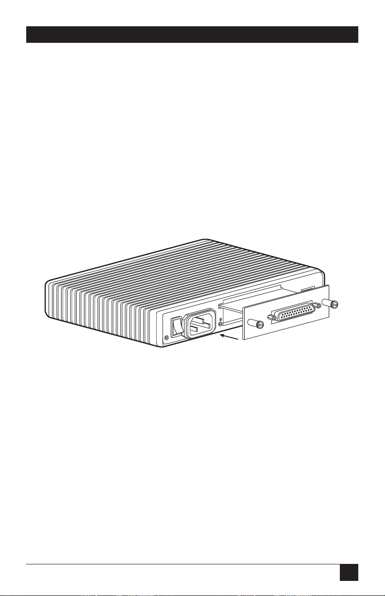
4.1 Connecting the Serial Port
The serial port interface on the CSU/DSU uses interchangeable modules to
connect to your DTE. Each module has a 50-pin card-edge connector on one side
and a serial port on the other. Figure 4-1 shows how an interface module plugs into
the back of the CSU/DSU.
Figure 4-1. Installing a Plug-In Serial Interface Module into the CSU/DSU.
4.1.1 C
HANGING THEMODULES
To install or remove an interface module (ordered separately; see page 10 for a
complete list of available modules), follow these steps.
To install an interface module:
1. Make sure the power switch is off. Leave the power cord plugged into a
grounded outlet to keep the CSU/DSU grounded.
2. Hold the module with the faceplate toward you and align the module with
the guide slots in the rear panel of the CSU/DSU.
Line
odule
ON I
OFF O
Quick-Connect Interface M
Interface Port
Page 31

30
MULTIPORT CSU/DSU
3. While keeping the module’s faceplate parallel with the CSU/DSU’s rear
panel, slide the module straight in, so that the card-edge contacts line up with
the socket inside the chassis.
NOTE
The card-edge connector should meet the socket when it is almost all
the way into the chassis. If you encounter much resistance, remove the
module and repeat steps 2 and 3.
4. With the card edge contacts aligned with the socket, firmly seat the module by
using your thumbs to apply pressure directly to the right and left edges of the
module faceplate. Applying moderate and even pressure should be sufficient
to seat the module. You should hear it “click” into place.
5. To secure the module in place, push the thumbscrews into the chassis and
turn the screws clockwise to tighten.
To remove an interface module:
1. Turn the power switch off. Leave the power cord plugged into a grounded
outlet to keep the unit grounded.
2. Loosen the two thumbscrews on the module by turning them counterclockwise.
3. Grasp the two thumbscrews and gently pull the module from the CSU/DSU.
Apply equal force to the thumbscrews to keep the module straight while you
remove it.
4.1.2 C
ONNECTING TO A
DTE D
EVICE
The serial port on most interface modules (all except the X.21 module) is hardwired as a DCE. Therefore, these modules plug into a DTE such as a terminal, PC,
or host. When connecting to your DTE device, use a straight-through cable of the
shortest possible length—we recommend 6 feet (1.8 m) or less. When purchasing
or constructing an interface cable, refer to the pin diagrams in Appendix A as a
guide.
4.1.3 C
ONNECTING TO A
DCE D
EVICE
If the CSU/DSU’s interface module is hard-wired as a DCE (all except the X.21
module), you must use a null-modem cable when connecting to a modem,
multiplexor, or other DCE device. This cable should be of the shortest possible
length—we recommend 6 feet (1.8 m) or less. When purchasing or constructing a
null-modem interface cable, use the pinout diagrams in Appendix A as a guide.
Page 32

31
MULTIPORT CSU/DSU
NOTE
Pinout requirements for null-modem applications vary widely between
manufacturers. If you have any questions about a specific application,
call Black Box Technical Support at 724-746-5500.
4.1.4 C
ONFIGURING THE
X.21 M
ODULE
The serial port on the X.21 interface module is default wired as a DCE, but may be
switched to a DTE. Simply reverse the orientation of the DCE/DTE strap, as
described below.
To reverse DCE/DTE orientation, remove the module according to the
instructions in Section 4.1.1. The DCE/DTE strap is located on the bottom side of
the module’s PC board. The arrows on the top of the strap indicate the
configuration of the X.21 port (for example, if the DCE arrows are pointing
toward the DB15 connector, the X.21 port is wired as a DCE). Reverse the
DCE/DTE orientation by pulling the strap out of its socket, rotating it 180°, then
plugging the strap back into the socket. You will see that the DCE/DTE arrows now
point in the opposite directions, showing the new configuration of the X.21 port.
Re-install the module according to the instructions in Section 4.1.1.
4.2 Connecting the Twisted-Pair Interface
The network interface is an 8-position modular connector. Connect this port to the
RJ-48 female jack provided by the digital data service provider. If you’re using the
CSU/DSU for private short-haul communication, the twisted-pair cable will
connect to this port. See Appendix A for the pin assignments of this connector.
The RJ-48 female connector on the CSU/DSU’s twisted-pair interface is prewired for a standard telco wiring environment. The signal/pin relationships are
shown in Figure 4-2.
Figure 4-2. CSU/DSU’s Twisted-Pair Line Interface.
1 (TX+)
2 (TX-)
3 (N/C)
4 (N/C)
5 (N/C)
6 (N/C)
7 (RX+)
8 (RX-)
1
2
3
4
5
6
7
8
Page 33

32
MULTIPORT CSU/DSU
4.3 Connecting Power
The CSU/DSU comes with a universal AC power supply that operates in
environments ranging from 100 to 253 VAC, with no reconfiguration. To connect
the power supply, follow these steps:
1. Attach the supplied power cord to the shrouded male IEC-320 connector on
the rear of the CSU/DSU.
2. Plug the power cord into a nearby AC power outlet.
3. Turn the rear power switch ON.
WARNING
There are no user-serviceable parts in the power-supply section of the
CSU/DSU. Only qualified service personnel should replace the fuse. Call
Black Box Technical Support at 724-746-5500 for more information.
Page 34

33
MULTIPORT CSU/DSU
5. Operation
After you properly configure and install the Multiport CSU/DSU, it should operate
transparently. This section describes power-on, the LED status monitors, and the
built-in loopback test modes.
5.1 Power-On
To apply power to the CSU/DSU, first read Section 4.3, and make sure that the
CSU/DSU is connected to the included power supply. Then turn on the rear
power switch.
5.2 LED Status Monitors
The CSU/DSU features 24 front-panel LEDs that monitor the line rate, power,
DTE signals, network connection, and test modes. Figure 5-1 shows the front-panel
location of each LED. Following Figure 5-1 is a description of each LED’s function.
Figure 5-1. Front Panel of the Multiport CSU/DSU.
• Power—Glows red when power is present.
• Line Rate—The corresponding LED will glow red to indicate the selected line
rate.
• TD and RD—Glow red to indicate an idle condition of binary 1 data on the
respective terminal interface signals. Green indicates binary 0 data.
• RTS—Glows green to indicate that the Request to Send signal from the DTE is
active.
Multiport CSU/DSU
Power
4.8 kbps
2.4 kbps
19.2 kbps
9.6 kbps
38.4 kbps
56 kbps
64 kbps
Error
No Signal
Line
StatusDTE StatusLine Rate
Test Mode
DSR
DTR
DCD
RTS
TD
CTS
RD
LocalNormalRemote-
Test Modes
Loop Pattern
-Errored
-Off
-Normal
Control Port
Page 35

34
MULTIPORT CSU/DSU
• CTS—Glows green to indicate that the Clear to Send signal from the modem
is active.
• DSR—Glows green to indicate that the CSU/DSU has asserted the Data Set
Ready signal.
• DCD—Glows red if no carrier signal is being received from the remote
modem. Green indicates that the remote modem’s carrier is being received.
• DTR—Glows green to indicate that the Data Terminal Ready signal from the
terminal is active.
• ER—Glows red to indicate that a bit error in the received signal is likely.
• TM—Glows red to indictae that the CSU/DSU has been placed in Test Mode.
Either the local or remote user can place the CSU/DSU in test mode.
• NS—Glows red to indicate that the local CSU/DSU has not yet connected with
the central office (or to the remote CSU/DSU when used in a campus shorthaul application).
5.3 Loop (V.54 and Telco) Diagnostics
The CSU/DSU offers three V.54 loop diagnostics and is compatible with two telco
loop diagnostics. Use these diagnostics to test the CSU/DSU and any
communication links. These tests can be activated physically from the front panel,
or via signals on the module interface.
5.3.1 O
PERATINGLOCALANALOGLOOPBACK
(LAL)
The Local Analog Loopback (LAL) test checks the operation of the local
CSU/DSU, and is performed separately on each CSU/DSU. As shown in Figure
5-2, any data sent to the local CSU/DSU in this test mode will be echoed
(returned) back to the user device (characters typed on the keyboard of a terminal
will appear on the terminal screen).
Figure 5-2. Local Analog Loop.
Local CSU/DSU
Page 36

35
MULTIPORT CSU/DSU
To perform a LAL test, follow these steps:
1. Activate LAL, in one of two ways:
a. Move the front panel toggle switch up to “Local,” or,
b. Activate the “LLB” signal on the DTE. If you are not sure which lead is the
LLB signal, refer to Appendix A.
2. Verify that the data terminal equipment is operating properly and can be
used for a test.
3. Perform a V.54 BER (bit error rate) test as described in Section 5.3.3. If the
BER test equipment indicates no faults, but the data terminal indicates a fault,
follow the manufacturer’s checkout procedures for the data terminal. Also,
check the interface cable between the terminal and the CSU/DSU.
5.3.2 O
PERATINGREMOTEDIGITALLOOPBACK
(RDL)
The Remote Digital Loopback (RDL) test checks the performance of both the
local and remote CSU/DSUs, as well as the communications link between them.
Any characters sent to the remote CSU/DSU in this test mode will be returned
back to the originating device (characters typed on the keyboard of the local
terminal will appear on the local terminal screen after having been passed to the
remote CSU/DSU and looped back).
Figure 5-3. Remote Digital Loop.
To perform an RDL test, follow these steps:
1. Activate RDL, in one of two ways:
a. Move the front panel toggle switch DOWN to “Remote,” or
b. Active the “RDL” signal on the DTE. If you are not sure which lead is the
RL signal, refer to Appendix A.
Local CSU/DSU
Remote CSU/DSU
Page 37

36
MULTIPORT CSU/DSU
2. Perform a bit error rate test (BERT) using the internal V.52 generator (as
described in Section 5.4), or using a separate BER Tester. If the BER test
indicates a fault, and the Local Line Loopback test was successful for both
CSU/DSUs, you may have a problem with the twisted-pair line between the
two units. Check the twisted-pair line for proper connections and continuity.
5.3.3 T
ELCO
T
ESTING
The digital service provider’s central office can perform CSU loop and DSU
diagnostic testing. These diagnostics allow the central office to evaluate the circuit
operation without making visits to the customer’s premises.
CSU Loop
The CSU loop is activated when the central office reverses the DC sealing current
that flows between the Transmit (TX) and Receive (RX) pairs. The CSU/DSU
recognizes this and loops the signals on the RX pairs back to the central office on
the TX pair. While the CSU loop is activated, the TM indicator lights.
Figure 5-4. CSU Loop.
5.4 Bit Error Rate (V.52) Diagnostics
The CSU/DSU offers two V.52 Bit Error Rate (BER) test patterns. You can invoke
them along with the LAL and RDL tests to evaluate the CSU/DSU(s) and the
communication links.
When a 511 or 2047 test is invoked, the CSU/DSU generates a pseudo-random
pattern of 511 bits (or 2047 bits) using a mathematical polynomial. The receiving
CSU/DSU then decodes the received bits using the same polynomial. If the
received bits match the agreed upon pseudo-random pattern, then the CSU/DSUs
and the communication links are functioning properly.
• 511: Initiates a built-in 511 bit pseudo-random pattern generator and detector.
DSU CSU
Digital Network
Page 38

37
MULTIPORT CSU/DSU
• 511 with Errors: Initiates a built-in 511 bit pseudo-random pattern generator
and detector. The test-pattern generator also injects intentional errors
approximately once per second, causing the Error LED to blink.
• 2047: Initiates a built-in 2047 bit pseudo-random pattern generator and
detector.
• 2047 with Errors: Initiates a built-in 2047 bit pseudo-random pattern generator
and detector. The test-pattern generator also injects intentional errors
approximately once per second, causing the Error LED to blink.
To perform a V.52 BER test, follow these steps:
1. Select the 511 or 2047 test pattern using DIP Switch 3-1.
2. Locate the “Pattern” toggle switch on the front panel of the CSU/DSU and
move it down to “Normal.” This activates the V.52 transmission and reception
of the selected test pattern. If there are errors in the received pattern, the
error LED will blink accordingly.
3. If the above test indicates that no errors are present, move the toggle switch
up to “Errored,” activating the BER test with intentional errors. If the test is
working properly, the local modem’s red error LED blinks approximately
once per second.
Page 39

38
MULTIPORT CSU/DSU
Appendix A: Interface Pin
Assignments
Table A-1. RS-232, RS-530 Interface Pin Description (DB25 female
connector) (DCE Configuration).
Pin # Signal
1 FG (Frame Ground)
2 TD (Transmit Data)
3 RD (Receive Data)
4 RTS (Request to Send)
5 CTS (Clear to Send)
6 DSR (Data Set Ready)
7 SGND (Signal Ground)
8 CD (Carrier Detect)
9 RC (Receive Timing-B)
10 CD (Carrier Detect-B)
11 XTC (External Transmit Clock)
12 TC (Transmit Clock-B)
13 CTS (Clear to Send)
14 TD (Transmit Data-B)
15 TC (Transmit Clock)
16 RD (Receive Data)
17 RC (Receive Clock)
18 LLB (Local Line Loop)
19 RTS (Request to Send)
20 DTR (Data Terminal Ready)
21 RDL (Remote Digital Loop)
22 DSR (Data Set Ready)
23 DTR (Data Terminal Ready)
24 XTC (External Transmit Clock)
25 TM (Test Mode)
Page 40

39
MULTIPORT CSU/DSU
Table A-2. V.35 Interface (M/34 female connector) (DCE Configuration).
Pin # Signal
B - - - - - - - - - - - - - - - - - - SGND (Signal Ground)
C - - - - - - - - - - - - - - - - - - RTS (Request to Send)
D - - - - - - - - - - - - - - - - - - CTS (Clear to Send)
E - - - - - - - - - - - - - - - - - - DSR (Data Set Ready)
F - - - - - - - - - - - - - - - - - - CD (Carrier Detect)
H - - - - - - - - - - - - - - - - - - DTR (Data Terminal Ready)
L - - - - - - - - - - - - - - - - - - LLB (Local Line Loop)
M - - - - - - - - - - - - - - - - - - TM (Test Mode)
N - - - - - - - - - - - - - - - - - - RDL (Remote Digital Loop)
P - - - - - - - - - - - - - - - - - - TD (Transmit Data-A)
R - - - - - - - - - - - - - - - - - - RD (Receive Data-A)
S - - - - - - - - - - - - - - - - - - TD (Transmit Data-B)
T - - - - - - - - - - - - - - - - - - RD (Receive Data-B)
U - - - - - - - - - - - - - - - - - - XTC (External Transmit Clock)
V - - - - - - - - - - - - - - - - - - RC (Receive Clock)
W- - - - - - - - - - - - - - - - - - XTC (External Transmit Clock)
X - - - - - - - - - - - - - - - - - - RC (Receive Clock-B)
Y - - - - - - - - - - - - - - - - - - TC (Transmit Clock-A)
AA - - - - - - - - - - - - - - - - - TC (Transmit Clock-B)
Page 41

40
MULTIPORT CSU/DSU
Table A-3. X.21 Interface (DB15 female connector) (DTE/DCE
Configuration).
Pin # Signal
1 - - - - - - - - - - - - - - - - - - Frame Ground
2 - - - - - - - - - - - - - - - - - - T (Transmti Data-A)
3 - - - - - - - - - - - - - - - - - - C (Control-A)
4 - - - - - - - - - - - - - - - - - - R (Receive Data-A)
5 - - - - - - - - - - - - - - - - - - I (Indication-A)
6 - - - - - - - - - - - - - - - - - - S (Signal Element Timing-A)
8 - - - - - - - - - - - - - - - - - - SGND (Signal Ground)
9 - - - - - - - - - - - - - - - - - - T (Transmit Data-B)
10 - - - - - - - - - - - - - - - - - C (Control-B)
11 - - - - - - - - - - - - - - - - - R (Receive Data-B)
12 - - - - - - - - - - - - - - - - - I (Indication-B)
13 - - - - - - - - - - - - - - - - - S (Signal Element Timing-B)
Page 42

41
MULTIPORT CSU/DSU
Appendix B: CSU/DSU Control
Port Pinout
The CSU/DSU control port is an 8-position connector that complies with
EIA/TIA-561.
Table B-1. CSU/DSU Control Port Pinout.
Pin Function RJ-45 Pin Number
Ground 4
Receive Data (to DTE) 5
Transmit Data (from DTE) 6
Page 43

42
MULTIPORT CSU/DSU
Appendix C: Quick Reference for
DIP Switch Settings
Table C-1. DIP Switch S1 Settings.
DIP Switch Position
S1 12345678
DTE Rate
2.4 kbps On On On
4.8 kbps On On Off
9.6 kbps On Off On
19.2 kbps Off On Off
38.4 kbps On On Off
DTE Rate= Off* On* On*
Line Rate*
RTS/CTS
Delay
Normal* Off*
Extended On
Anti-Stream Timer
Disabled On
Enabled* Off*
Data Format
Synchronous* Off*
Asynchronous On
Asynchronous Character Length
10 bits* Off*
11 bits On
Extended Signaling Rate
-2.5% to +1%* Off*
-2.5% to +2.3% On
*Factory default settings for DIP Switch S1.
For more information about DIP Switch S1 settings, see Section 3.1.1.
Page 44

43
MULTIPORT CSU/DSU
Table C-2. DIP Switch S2 Settings.
DIP Switch Position
S2 12345678
Line Rate
2.4 kbps On On On
4.8 kbps On On Off
9.6 kbps On Off On
19.2 kbps On Off Off
56 kbps* Off* On* On*
64 kbps Off On Off
**See note. Off Off Off
Clock Mode
External (DTE) On Off
Network (Looped)* Off* Off*
Internal (Master) On On
Campus Clock Off On
Force RTS
Forced On On
Follows DTE Signal* Off*
Data Set Ready During Local Loopback Test
DSR on during local line loop On
DSR off during local line loop* Off*
Circuit Assurance
Enabled On
Disabled* Off*
**NOTE
Forces configuration pointer to default to hardware control.
*Factory default settings for DIP Switch S2.
For more information about DIP Switch S2 settings, see Section 3.1.2.
Page 45

44
MULTIPORT CSU/DSU
Table C-3. DIP Switch S3 Settings.
DIP Switch Position
S3 12345678
Test Pattern
511 BER* Off*
2047 BER On
Response to RDL Request
Enabled* Off*
Disabled On
Front Panel Switch
Enabled* Off*
Disabled On
DTE Loop Request Line
Enabled Off
Disabled* On*
Not used Off* Off*
Control Port Data Rate
9.6 kbps On Off
19.2 kbps* Off* Off*
NOTE
DIP Switches S3-5 and S3-6 are reserved for future use and must remain
in the Off position.
*Factory default settings for DIP Switch S3.
For more information about DIP Switch S3 settings, see Section 3.1.3.
Page 46

1000 Park Drive • Lawrence, PA 15055-1018 • 724-746-5500 • Fax 724-746-0746
© Copyright 1999. Black Box Corporation. All rights reserved.
 Loading...