

Black Box MT195A-T1, MT196A-E1 Owner's Manual
®
BLACK BOX
NETWORK SERVICES
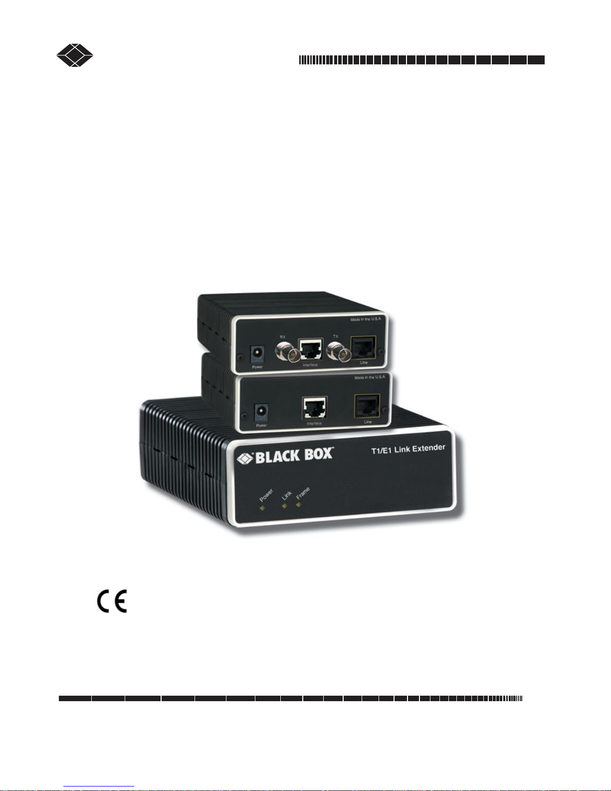
T1/E1 Link Extenders
®
OCTOBER 2007
MT195A-T1
MT196A-E1
Important
This is a Class A device and is intended for use in a light industrial environment. It is not intended nor
approved for use in an industrial or residential environment.
CUSTOMER
SUPPORT
INFORMATION
Order toll-free in the U.S. 24 hours, 7 A.M. Monday to midnight Friday: 877-877-BBOX
FREE technical support, 24 hours a day, 7 days a week: Call 724-746-5500 or fax 724-746-0746
Mail order: Black Box Corporation, 1000 Park Drive, Lawrence, PA 15055-1018
Web site: www.blackbox.com • E-mail: info@blackbox.com

T1/E1 LINK EXTENDERS
CE NOTICE
We certify that the apparatus identified in this document conforms to the requirements of Council Directive 1999/5/EC on the approximation of the laws of the
member states relating to Radio and Telecommunication Terminal Equipment
and the mutual recognition of their conformity.
RADIO AND TV INTERFERENCE
This equipment generates and uses radio frequency energy, and if not installed
and used properly—that is, in strict accordance with the manufacturer's instructions—may cause interference to radio and television reception. This equipment
has been tested and found to comply with the limits for a Class A computing
device in accordance with the specifications in Subpart B of Part 15 of FCC rules,
which are designed to provide reasonable protection from such interference in a
commercial installation. However, there is no guarantee that interference will not
occur in a particular installation. If the equipment causes interference to radio or
television reception, which can be determined by disconnecting the cables, try to
correct the interference by one or more of the following measures: moving the
computing equipment away from the receiver, re-orienting the receiving antenna,
and/or plugging the receiving equipment into a different AC outlet (such that the
computing equipment and receiver are on different branches).
FCC PART 68
This equipment complies with Part 68 of FCC rules and the requirements adopted
by ACTA. On the bottom side of this equipment is a label that contains—among
other information—a product identifier in the format US: AAAEQ##TXXXX. If
requested, this number must be provided to the telephone company.
The method used to connect this equipment to the premises wiring and telephone
network must comply with the applicable FCC Part 68 rules and requirements
adopted by the ACTA.
If this equipment causes harm to the telephone network, the telephone company
will notify you in advance that temporary discontinuance of service may be
required. But if advance notice isn’t practical, the telephone company will notify
the customer as soon as possible. Also, you will be advised of your right to file a
complaint with the FCC if you believe it is necessary.
The telephone company may make changes in its facilities, equipment, operations or procedures that could affect the operation of the equipment. If this happens the telephone company will provide advance notice in order for you to make
necessary modifications to maintain uninterrupted service.
2

T1/E1 LINK EXTENDERS
If trouble is experienced with this equipment, for repair or warranty information,
please contact our company. If the equipment is causing harm to the telephone
network, the telephone company may request that you disconnect the equipment
until the problem is resolved.
Connection to party line service is subject to state tariffs. Contact the state public
utility commission, public service commission or corporation commission for
information.
INDUSTRY CANADA NOTICE
This equipment meets the applicable Industry Canada Terminal Equipment Technical Specifications. This is confirmed by the registration number. The abbreviation, IC, before the registration number signifies that registration was performed
based on a Declaration of Conformity indicating that Industry Canada technical
specifications were met. It does not imply that Industry Canada approved the
equipment.
This Declaration of Conformity means that the equipment meets certain telecommunications network protective, operational and safety requirements. The
Department does not guarantee the equipment will operate to the user's satisfaction. Before installing this equipment, users should ensure that it is permissible to
be connected to the facilities of the local telecommunications company. The
equipment must also be installed using an acceptable method of connection. In
some cases, the company’s inside wiring associated with a single line individual
service may be extended by means of a certified connector assembly (telephone
extension cord). The customer should be aware that compliance with the above
condition may not prevent degradation of service in some situations. Repairs to
some certified equipment should be made by an authorized maintenance facility
designated by the supplier. Any repairs or alterations made by the user to this
equipment, or equipment malfunctions, may give the telecommunications company cause to request the user to disconnect the equipment. Users should ensure
for their own protection that the ground connections of the power utility, telephone lines and internal metallic water pipe system, are connected together. This
protection may be particularly important in rural areas.
3

T1/E1 LINK EXTENDERS
COMPLIANCE
EMC
FCC Part 15, Class A
•
•
EN55022, Class A
EN55024
•
SAFETY
•
UL 60950-1/CSA C22.2 N0. 60950-1
IEC/EN60950-1
•
•
AS/NZS 60950-1
PSTN REGULATORY
•
FCC Part 68
CS03
•
•
TBR12 & 13
•
AS/ACIF S016:2001
AS/ACIF S043:2003
•
4
WARNING
T1/E1 LINK EXTENDERS
SAFETY WHEN WORKING WITH ELECTRICITY
• This device contains no user serviceable parts. The
equipment shall be returned to Black Box for repairs, or
repaired by qualified service personnel.
• The external AC adaptor shall be a listed limited
power source that incorporates a disconnect device and
shall be positioned within easy reach of the operator.
Ensure that the AC power cable meets all applicable
standards for the country in which it is to be installed,
and that it is connected to a wall outlet which has earth
ground.
• Do not work on the system or connect or disconnect
cables during periods of lightning activity.
In accordance with the requirements of council directive 2002/96/EC on Waste of Electrical and Electronic
Equipment (WEEE), ensure that at end-of-life you separate this product from other waste and scrap and deliver
to the WEEE collection system in your country for recycling.
TRADEMARKS USED IN THIS MANUAL
All applied-for and registered trademarks are the property of their respective owners.
5

T1/E1 LINK EXTENDERS
CONTENTS
CE Notice .................................................................................................... 2
Radio and TV Interference.......................................................................... 2
FCC Part 68................................................................................................. 2
Industry Canada Notice............................................................................... 3
Compliance.................................................................................................. 4
Safety When Working With Electricity ...................................................... 5
Trademarks Used In This Manual............................................................... 5
1. General Information ....................................................................................8
1.1 Features ...............................................................................................8
1.2 Description ......................................................................................... 8
2. Installation................................................................................................... 9
2.1 Connecting Power ............................................................................10
2.2 Power Input Connector..................................................................... 10
2.2.1 External AC universal power supply .....................................10
2.3 Connecting the Line Port.................................................................. 11
2.4 Connecting the Circuit Interface ...................................................... 11
3. Operation................................................................................................... 12
3.1 Front Panel LED Status Monitors ....................................................12
3.2 Configuration and Dip Switches ...................................................... 13
3.2.1 Switch S1-7: Line Build Out .................................................13
A. Specifications ............................................................................................ 14
A.1 Circuit Rates .....................................................................................14
A.2 Circuit Interface ................................................................................14
A.3 Circuit Defaults ................................................................................14
A.4 Circuit Connector .............................................................................14
A.5 LED Indicators .................................................................................14
A.6 Power and Power Supply Specifications ..........................................14
A.7 Environmental ..................................................................................15
A.8 Transmission Line ............................................................................15
A.9 Line Coding ......................................................................................15
6
 Loading...