

Page 1

1000 Park Drive • Lawrence, PA 15055-1018 • 724-746-5500 • Fax 724-746-0746
© Copyright 1999. Black Box Corporation. All rights reserved.
Page 2

CUSTOMER
SUPPORT
INFORMATION
Order toll-free in the U.S. 24 hours, 7 A.M. Monday to midnight Friday: 877-877-BBOX
FREE technical support, 24 hours a day, 7 days a week: Call 724-746-5500 or fax 724-746-0746
Mail order: Black Box Corporation, 1000 Park Drive, Lawrence, PA 15055-1018
Web site: www.blackbox.com • E-mail: info@blackbox.com
APRIL 1999
MT160A PS462A
MT161C-25 PS463A
MT161C-V35 RM202
PS460A RM204
PS460AE RM208
PS461A RM216
MicroCSU/DSU Cards
MicroRACK
ON
OFF
Power
MicroRack System
AC Power Supply
Page 3

Page 4

1
TRADEMARKS
TRADEMARKS USED IN THIS MANUAL
AT&T is a registered trademark of AT&T.
MCI is a registered trademark of MCI Telecommunications Corporation.
Sprint is a registered trademark of U.S. Sprint Communications Ltd.
Any trademarks used in this manual are acknowledged to be the property of the
trademark owners.
Page 5

2
MicroCSU/DSU Cards and MicroRacks
FEDERAL COMMUNICATIONS COMMISSION
AND
INDUSTRY CANADA
RADIO FREQUENCY INTERFERENCE STATEMENTS
This equipment generates, uses, and can radiate radio frequency energy and if not
installed and used properly, that is, in strict accordance with the manufacturer’s
instructions, may cause interference to radio communication. It has been tested
and found to comply with the limits for a Class A computing device in accordance
with the specifications in Subpart J of Part 15 of FCC rules, which are designed to
provide reasonable protection against such interference when the equipment is
operated in a commercial environment. Operation of this equipment in a
residential area is likely to cause interference, in which case the user at his own
expense will be required to take whatever measures may be necessary to correct
the interference.
Changes or modifications not expressly approved by the party responsible
for compliance could void the user’s authority to operate the equipment.
This digital apparatus does not exceed the Class A limits for radio noise emission from
igital apparatus set out in the Radio Interference Regulation of Industry Canada.
Le présent appareil numérique n’émet pas de bruits radioélectriques dépassant les limites
applicables aux appareils numériques de la classe A prescrites dans le Règlement sur le
brouillage radioélectrique publié par Industrie Canada.
Page 6

3
NOM STATEMENT
NORMAS OFICIALES MEXICANAS (NOM)
ELECTRICAL SAFETY STATEMENT
INSTRUCCIONES DE SEGURIDAD
1. Todas las instrucciones de seguridad y operación deberán ser leídas antes de
que el aparato eléctrico sea operado.
2. Las instrucciones de seguridad y operación deberán ser guardadas para
referencia futura.
3. Todas las advertencias en el aparato eléctrico y en sus instrucciones de
operación deben ser respetadas.
4. Todas las instrucciones de operación y uso deben ser seguidas.
5. El aparato eléctrico no deberá ser usado cerca del agua—por ejemplo, cerca
de la tina de baño, lavabo, sótano mojado o cerca de una alberca, etc..
6. El aparato eléctrico debe ser usado únicamente con carritos o pedestales que
sean recomendados por el fabricante.
7. El aparato eléctrico debe ser montado a la pared o al techo sólo como sea
recomendado por el fabricante.
8. Servicio—El usuario no debe intentar dar servicio al equipo eléctrico más allá
a lo descrito en las instrucciones de operación. Todo otro servicio deberá ser
referido a personal de servicio calificado.
9. El aparato eléctrico debe ser situado de tal manera que su posición no
interfiera su uso. La colocación del aparato eléctrico sobre una cama, sofá,
alfombra o superficie similar puede bloquea la ventilación, no se debe colocar
en libreros o gabinetes que impidan el flujo de aire por los orificios de
ventilación.
10. El equipo eléctrico deber ser situado fuera del alcance de fuentes de calor
como radiadores, registros de calor, estufas u otros aparatos (incluyendo
amplificadores) que producen calor.
11. El aparato eléctrico deberá ser connectado a una fuente de poder sólo del
tipo descrito en el instructivo de operación, o como se indique en el aparato.
Page 7

4
MicroCSU/DSU Cards and MicroRacks
12. Precaución debe ser tomada de tal manera que la tierra fisica y la polarización
del equipo no sea eliminada.
13. Los cables de la fuente de poder deben ser guiados de tal manera que no
sean pisados ni pellizcados por objetos colocados sobre o contra ellos,
poniendo particular atención a los contactos y receptáculos donde salen
del aparato.
14. El equipo eléctrico debe ser limpiado únicamente de acuerdo a las
recomendaciones del fabricante.
15. En caso de existir, una antena externa deberá ser localizada lejos de las lineas
de energia.
16. El cable de corriente deberá ser desconectado del cuando el equipo no sea
usado por un largo periodo de tiempo.
17. Cuidado debe ser tomado de tal manera que objectos liquidos no sean
derramados sobre la cubierta u orificios de ventilación.
18. Servicio por personal calificado deberá ser provisto cuando:
A: El cable de poder o el contacto ha sido dañado; u
B: Objectos han caído o líquido ha sido derramado dentro del aparato; o
C: El aparato ha sido expuesto a la lluvia; o
D: El aparato parece no operar normalmente o muestra un cambio en su
desempeño; o
E: El aparato ha sido tirado o su cubierta ha sido dañada.
Page 8

5
CONTENTS
Contents
Chapter Page
1. Specifications ........................................................................................................6
2. Introduction ........................................................................................................10
2.1 Overview ....................................................................................................10
2.2 Features......................................................................................................11
3. Before You Begin ................................................................................................12
3.1 Dedicated DDS Configuration ................................................................12
3.2 Campus Area Short-Haul Configuration ................................................12
3.3 Network Interface Connection ................................................................12
4. Configuration ......................................................................................................13
4.1 Front-Panel LEDs ......................................................................................13
4.2 Source of Configuration ..........................................................................14
4.2.1 Hardware Switches ..........................................................................15
4.2.2 Software Switches ............................................................................21
4.3 Rear Card Configuration..........................................................................29
4.3.1 MicroCSU/DSU DB25 Rear Strap Settings ..................................31
4.3.2 MicroCSU/DSU V35 Rear Strap Settings ....................................32
5. Installation ..........................................................................................................34
6. DDS Testing ........................................................................................................38
6.1 Local Analog Loopback Testing ..............................................................38
6.2 Remote Digital Loopback Testing ..........................................................39
6.3 V.52 BER Test Generator..........................................................................40
6.4 Telco Testing ............................................................................................40
6.4.1 CSU Loop ........................................................................................41
6.4.2 DSU Loop ........................................................................................41
Appendix A. Cable Recommendations ..................................................................42
Appendix B. Interface Pin Assignment ..................................................................43
B.1 DDS Interface ............................................................................................43
B.2 M/34 Connector, Terminal Interface ....................................................43
B.3 DB25 Connector, Terminal Interface ....................................................44
Appendix C. Transmitter Clock Source During Test Loops ................................45
Page 9

6
MicroCSU/DSU Cards and MicroRacks
1. Specifications
MicroCSU/DSUs (MT160A, MT161C-25, MT161C-V35)
DDS Type — Dedicated DDS
Transmission Format — Asynchronous, synchronous
Internal Interface — Connection to rack chassis via a 50-pin male card edge
External Interface — DB25 female, M/34 female, RJ-48S
Standards — AT&T 62310 compliant
DDS Line Rates — 2.4, 4.8, 9.6, 19.2, 56, and 64 Kbps
DTE Rates — 2.4, 4.8, 9.6, 19.2, 38.4, 56, 57.6, and 64 Kbps
Leads Supported — MT160A, MT161C-V35: B, C, D, E, F, H, L, M, N, P, R, S, T, U,
V, W, X, Y, AA; MT161C-25: 1–9, 11, 12, 14–18, 20, 21, 24, 25
Control Port — Configuration and diagnostics
Transmission Line — 4-wire
Applications — DDS point-to-point or multipoint; campus-area point-to-point
Indicators — (10) LEDs: POWER, TD, RD, CTS, CD, DTR, NS, OS, ER, and TM
Operation — Full duplex
Clocking — Internal, External, Recovered
Diagnostics — V.54 compliant local and remote loopback tests; V.52 compliant 511
BER test, telco CSU and DSU loops
Power Supply — Rackmount power supply is switchable between 120 and 240 VAC;
chassis supplies 10 VAC to the MicroCSU/DSU, typical consumption is 1.5W per
slot
Fuse — 400 mA for 120V applications; 200 mA for 240V applications
Operating Temperature — 32° to 114°F (0° to 45°C)
Page 10

7
CHAPTER 1: Specifications
Storage Temperature — -40° to 176°F (-40° to 80°C)
Humidity — Up to 95%, noncondensing
Size — MT160A: 2.5"H x 5"W x 1"L (6.4 x 12.7 x 2.5 cm); MT161C-25, MT161C-
V35: 2.5"H x 4.5"W x 1"L (6.4 x 11.4 x 2.5 cm)
Weight — 1 lb. (0.5 kg)
MicroRacks (RM202, RM204, RM208, RM216)
Indicators — Indicators are on the front card (MT160A)
Number of Slots — RM202: 2; RM204: 4; RM208: 8; RM216: 16
Power Source — Internal
Input Voltage — 120 VAC
Input Current/Amps — 200 mA
Input Connector Type — IEC 950
Connector Style — On the CSU/DSU rear cards
Operating Temperature — 32° to 114°F (0° to 45°C)
Storage Temperature — -40° to 176°F (-40° to 80°C)
Humidity — 0 to 95%, noncondensing
Size — RM202: 3.5"H x 3.5"W x 7.5"D (8.9 x 8.9 x 19.1 cm); RM204: 3.5"H x 5.5"W
x 7.5"D (8.9 x 14 x 19.1 cm); RM208: 3.5"H x 9.5"W x 7.5"D (8.9 x 24.1 x 19.1 cm);
RM216: 3.5"H x 19"W x 7.5"D (8.9 x
48.3 x 19.1 cm)
Weight — RM202, RM208, RM216: 5 lb. (2.2 kg); RM204: 4 lb. (1.8 kg)
Power Supply (PS460A)
Power Source — Internal
Input Voltage — 110 volts AC
Page 11

8
MicroCSU/DSU Cards and MicroRacks
Power Supply (PS460AE)
Power Source — Internal
Fuses — (4) Included (2 in the drawer and 2 spares)
Input Voltage — 115 or 230 volts AC, autosensing
Power Supply (PS461A)
Power Source — Internal
Input Voltage — 48 volts DC
Input Connector Type — PS461A: Terminal screw connections
Indicators — Power, DC input
Size — 3.5"H x 1.5"W x 7"D (8.9 x 3.8 x 17.8 cm)
Weight — 1 lb. (0.5 kg)
Power Supplies (PS462A and PS463A)
F
RONT
P
OWER-SUPPLYCARD
Power Supply — PS462A: 24 VDC; PS463A: 12 VDC
Input Voltage — PS462A: 13–36VDC; PS463A: 10–20 VDC
Input Protection — PS462A: Triggered at 39 VDC; PS463A: Triggered
at 22 VDC
Maximum Input
Current — PS462A: 2A @ 18 VDC; PS463A: 4A @ 10 VDC
Isolation Voltage — 500V RMS, input to output
Output Voltage — 12 VAC @ 2A
Output Power — 24W
Switches — Power on/off
Indicators — Power, DC Input
Page 12

9
CHAPTER 1: Specifications
R
EARPOWER-SUPPLYCARD
Connection — Cage-clamp terminal block with +DC In, -DC In, Frame
Ground, Alarm, Alarm C, +DC Out, -DC Out
Wire — 26-14 solid or stranded cable
Alarm — Opens when power is attached and closes when power
is disconnected
Page 13

10
MicroCSU/DSU Cards and MicroRacks
2. Introduction
2.1 Overview
The MicroCSU/DSU operates either synchronously or asynchronously and
supports data rates to 64 Kbps. An easily accessible control port allows the user to
enable diagnostic utilities, including V.54 and V.52 test. Ten easy-to-read LEDs
monitor data and control signals.
The Cards are AT&T
®
compliant and are fully compatible with DDS, Clear
Channel 64, and other digital services available from major service providers
including AT&T, Sprint
®
, and MCI®. They can also be used as high-speed modems
for private twisted pair.
In order for your MicroCSU/DSU to function properly, you will need one front
card (MT160A), one rear card (MT161C-25 or MT161C-V35), one power supply
(PS460A, PS461A, PS462A, or PS463A), and one MicroRack (RM202, RM204,
RM208, or RM216).
The MicroCSU/DSU Cards are designed to mount in any size MicroRack.
Depending on which model MicroRack you choose, it will hold up to 16 cards.
Measuring only 3.5 inches high, the Card is designed to occupy only 2U in a 19inch rack. The MicroRacks are powered by either the MicroRack AC Power Supply
(PS460A) or a MicroRack DC Power Supply (PS461A, PS462A, or PS463A). The
MicroRacks use mid-plane architecture (the front card can be plugged into
different rear cards). Therefore, the MicroCSU/DSU Cards can have several
interface options and can be switched with other short-haul cards.
The table on the next page lists the names and codes of the products described
in this manual.
Page 14

11
CHAPTER 2: Introduction
Code Product Name
MT160A MicroCSU/DSU Front Card
MT161C-25 MicroCSU/DSU DB25 Rear
MT161C-V35 MicroCSU/DSU V35 Rear
PS460A MicroRack AC Power Supply
PS461A MicroRack 48-VDC Power Supply
PS462A MicroRack 24-VDC Power Supply
PS463A MicroRack 12-VDC Power Supply
RM202 MicroRack 2
RM204 MicroRack 4
RM208 MicroRack 8
RM216 MicroRack 16
2.2 Features
• Operates over dedicated digital lines.
• Supports rates of 56 and 64 Kbps and all sub-rates.
• Provides both RS-232 and V.35 interfaces.
• Features V.52 and V.54-compliant tests.
• Easy-to-read LEDs monitor data and line signals.
• AT&T 62310 compliant.
• Can be used as a high-speed modem for private twisted pair.
Page 15

12
MicroCSU/DSU Cards and MicroRacks
3. Before You Begin
This chapter describes how to install the MicroCSU/DSU for dedicated operation
or for use as a campus-area short-haul modem.
3.1 Dedicated DDS Configuration
The MicroCSU/DSU can easily be configured for dedicated DDS operation by
means of the DIP switches on the bottom of the enclosure. Set the Line Rate
to match the rate of service to which you subscribe. Set the Mode switches for
Network Clocking. The Rate Converter and Data Format options should be set
as required for your application. The remaining options may also need to be set
depending on your terminal equipment and your application.
3.2 Campus Area Short-Haul Configuration
The unit can also be used for campus area point-to-point short-haul applications
on private twisted-pair wires. Set the Line Rates the same on both units. Set the
Mode switch for the appropriate Transmit Clock Mode for your application.
Internal, External, and Looped Clock Modes are available. Set the remaining
options as needed by your terminal equipment or your application.
3.3 Network Interface Connection
The Network Interface is an 8-position modular connector. Connect this port to
the RJ-48S jack provided by the digital data service provider. If you are using the
MicroCSU/DSU for private short-haul communication, the twisted-pair cable will
connect to this port. See Appendix B for the pin assignments of this connector.
Page 16

13
CHAPTER 4: Configuration
4. Configuration
Before you can operate your MicroCSU/DSU, you must configure the unit. This
chapter describes reading the LED status monitors, setting the DIP switches, and
using the control port.
4.1 Front-Panel LEDs
There are ten front-panel status LEDs that indicate the condition of the CSU/DSU
and the communication link. Figure 1 shows the location of each LED. Following
Figure 1 is a description of each LED’s function.
Figure 1. The MicroCSU/DSU’s LEDs.
DTR Power
TD
RD
CD
CTS
NS
OS
TM
ER
Remote Analog
511 511/E
Page 17

14
MicroCSU/DSU Cards and MicroRacks
• POWER will glow red when the proper power is applied to the rack.
• TD and RD will glow red to indicate an Idle condition or Binary “1” data on
the respective terminal interface signals. Green indicates Binary “0” data.
• CTS will glow red to indicate an Off condition. Green indicates an On
condition. When on, the unit is ready to send data. If CTS remains off,
check the Forced RTS, Circuit Assurance, and Anti-Streaming Settings.
• CD will glow red to indicate that the Idle code is being received. Green
indicates that data is being received.
• DTR will glow to indicate that the DTR signal from the terminal is active.
• NS indicates No Signal. This means the MicroCSU/DSU receiver does not
detect a signal from the digital service provider (or, in the case of short-haul
operation, from the remote MicroCSU/DSU). If NS is lit, check for an
unplugged cable, broken wire, or an incorrect Line Rate selection.
• OS indicates Out-of-Service. This means the MicroCSU/DSU has received an
Out-of-Service signal from the digital service provider and indicates a problem
with the service provider’s equipment. If this condition persists, contact your
service provider.
• ER indicates the likelihood of a Bit Error in the received signal. ER will flash
if the MicroCSU/DSU receives illegal bi-polar violations. During the 511 or
511/E test, ER will flash to indicate that the Test Pattern Detector has detected
a bit error.
• TM indicates Test Mode. It will light if the unit is placed into a test mode. The
unit can be placed in test mode by the local user, by the remote user, or by the
service provider.
4.2 Source of Configuration
The unit defaults to the use of Hardware Switches for configuration. It can also be
set to use Soft Switches for configuration, in which case the Hardware Switches will
be ignored.
Page 18

15
CHAPTER 4: Configuration
4.2.1 H
ARDWARESWITCHES
It is possible to override the Soft Switches and force the unit to use the Hardware
Switches. To do this, powerup the unit once with the Line Rate (SW1-1, 1-2, 1-3)
set to OFF, OFF, OFF. Then set the Hardware Switches as you require and
powerup the unit again.
Figure 2. The MicroCSU/DSU Front Card, bottom view, showing the
location of the DIP switches.
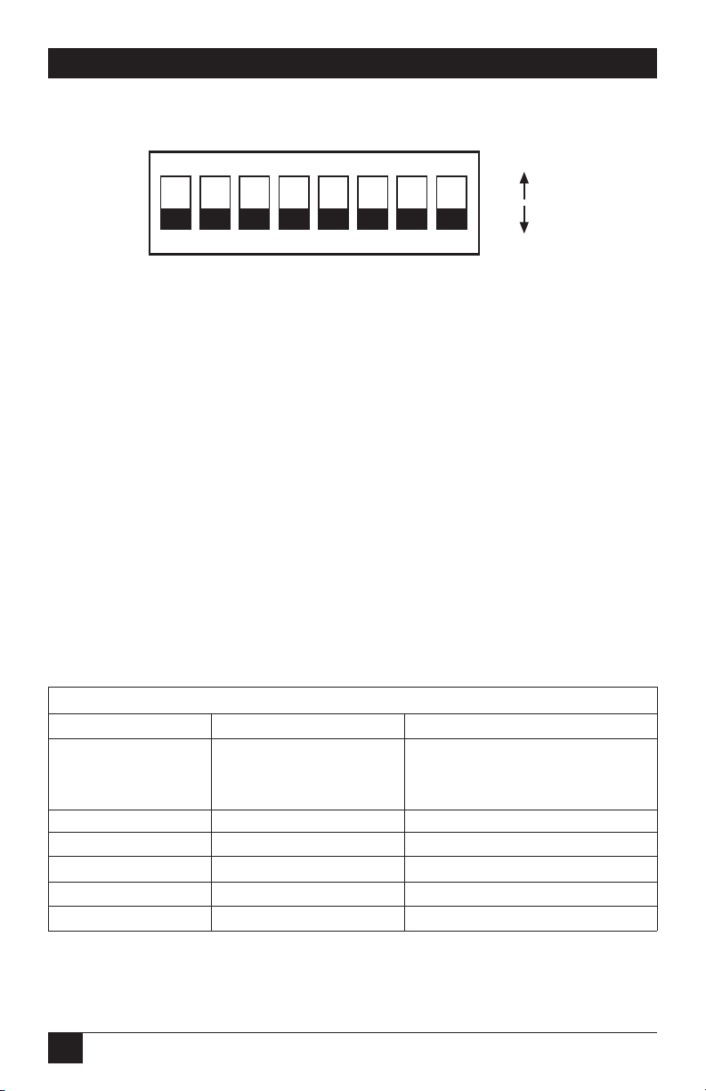
The sixteen DIP switches can be configured as either On or Off. Figure 3 shows the
orientation of the DIP switches with respect to ON/OFF positions.
SW2SW1
Front
Interface
Driver
Board
MSD LSD
Address Rotary
Switches
Page 19
16
MicroCSU/DSU Cards and MicroRacks
Figure 3. Close-up of DIP switches showing ON/OFF positions.
T
ERMINALINTERFACE
The MicroCSU/DSU supports RS-232 and V.35 terminal interface electrical
specifications by means of an interface driver board. Install this board by observing
the markings “This side up for RS-232,” “This side up for V.35,” and “Front.” (The
arrow should point toward the front panel.)
S
WITCHSET
1
The configuration switches on switch set 1 (SW1) allow you to specify Line Rate,
Circuit Assurance, Force RTS, Character Length, Data Format, and DSR System
Status. Table 1 (on the next page) summarizes the SW1 switch settings, including
the factory defaults. Following the chart is a description of each switch setting.
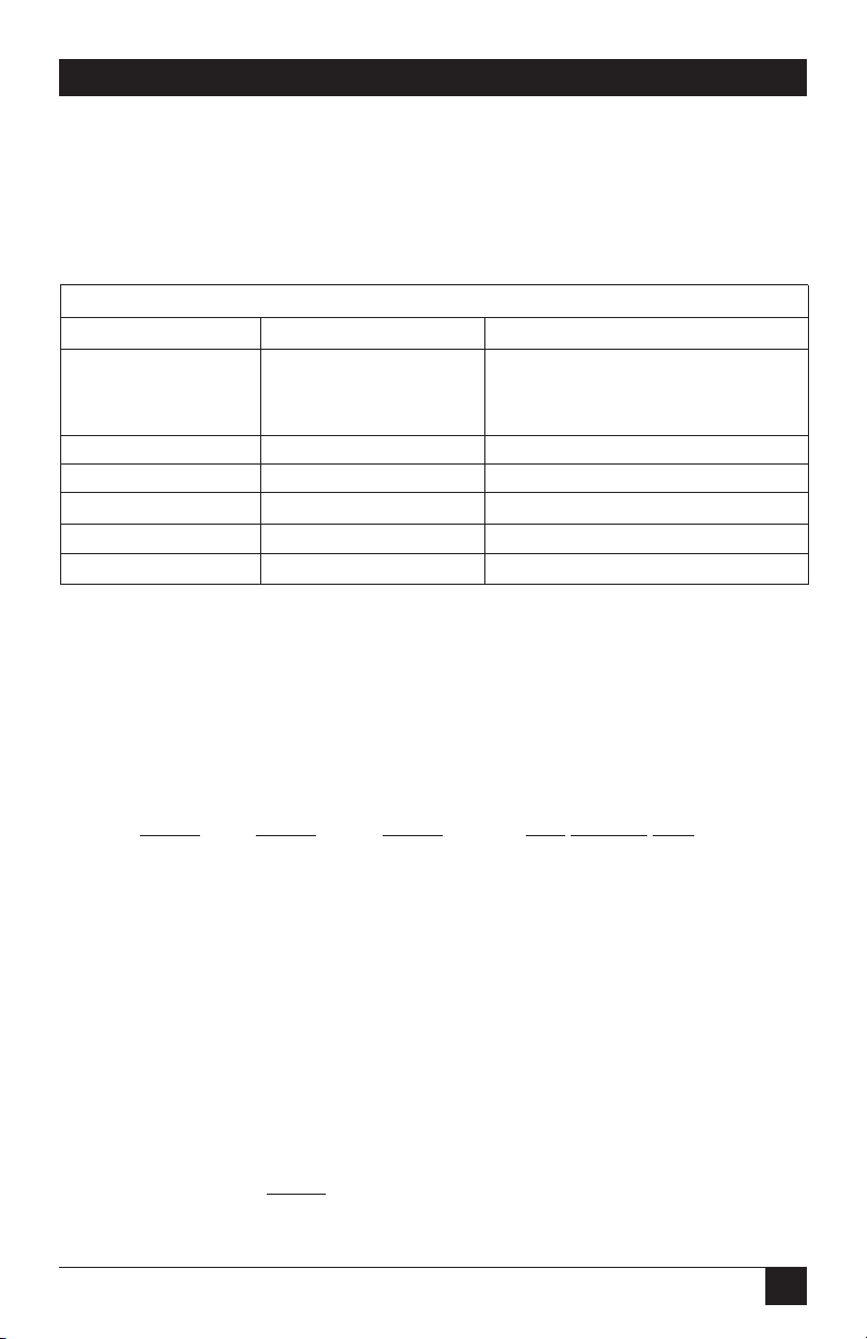
SWITCH SET 1 SUMMARY
Position Function Factory Default
Switch SW1-1 Line Rate Off 56,000 bps
Switch SW1-2 On
Switch SW1-3 On
Switch SW1-4 Circuit Assurance Off Disabled
Switch SW1-5 Force RTS Off Enabled
Switch SW1-6 Character Length Off 10-Bit
Switch SW1-7 Data Format Off Synchronous
Switch SW1-8 DSR System Status Off Disabled
Table 1. Summary of switch settings and factory defaults
12345678
ON
ON
OFF
Page 20

17
CHAPTER 4: Configuration
Line Rate
These switches control the signaling rate on the line or RJ-48S port of the unit.
They should be set to match the speed of your digital service.
SW1-1 SW1-2 SW1-3 Setting
On On On 2.4 Kbps
On On Off 4.8 Kbps
On Off On 9.6 Kbps
On Off Off 19.2 Kbps
Off On On 56 Kbps
Off On Off 64 Kbps
Off Off Off Force configuration
pointer to default to
Hardware Switches
Circuit Assurance
The transmitter and the CTS output can be configured to go On only when a
working communication circuit is established. If Circuit Assurance is used, enable
it on only one end of the communication link.
SW1-4 Circuit Assurance Description
On Enabled CTS will go low and the transmitter will be
held off if the receiver is in the No Signal
state or CD is low
Off Disabled The transmitter and CTS will operate
without regard to the receiver state
Force RTS
The RTS input can be forced on, ignoring the terminal’s RTS signal. RTS controls
the transmitter by either sending the user’s data or sending an idle code.
SW1-5 RTS Forced On Description
Off Enabled An On (high) condition is transmitted
regardless of the state of this unit’s RTS
input
On Disabled The RTS input controls the transmitter
Page 21

18
MicroCSU/DSU Cards and MicroRacks
Character Length
In asynchronous data format, 10- and 11-bit characters are supported. This setting
is ignored in synchronous data format.
Character Description
SW1-6 Character Length Start Data bits Parity Stop bits
Off 10-bit 1 8 None 1 or more
1 7 1 1 or more
1 7 None 2
On 11-bit 1 8 1 1 or more
1 9 None 1 or more
Data Format
The data-format selection controls whether an async-to-sync conversion is
performed.
SW1-7 Data Format
On Asynchronous
Off Synchronous
DSR System Status
The behavior of the DSR output during performance of a local loop can be
controlled.
SW1-8 DSR System Status Description
On Enabled DSR remains high (On) during the
Analog Loop
Off Disabled DSR goes low (Off) during the Analog
Loop
Page 22
19
CHAPTER 4: Configuration
S
WITCHSET
2
The configuration switches on switch set 2 (SW2) control the Rate Converter,
Loop Control from Terminal, Mode of Operation, Anti-Stream Timer, and CTS
Delay. Table 2 summarizes SW2 switch settings, including the factory defaults.
Following Table 2 is a description of each switch setting.
SWITCH SET 2 SUMMARY
Position Function Factory Default
Switch SW2-1 Rate Converter Off Disabled
Switch SW2-2 Off
Switch SW2-3 Off
Switch SW2-4 Loop Control from DTE Off Disabled
Switch SW2-5 Mode Off Network
Switch SW2-6 Off Clock
Switch SW2-7 Anti-Streaming Timer On Disabled
Switch SW2-8 CTS Display Off Normal
Table 2. Summary of switch settings and factory defaults
Rate Converter
The rate converter allows a 56 or 64K line rate to be used for operation at slower
data rates. If the rate converter is disabled, the DTE interface rate is the same as
the line rate.
SW2-1 SW2-2 SW2-3 DTE Interface Rate
On On On 2.4 Kbps
Off On On 4.8 Kbps
On Off On 9.6 Kbps
Off Off On 19.2 Kbps
On On Off 38.4 Kbps
Off Off Off Disabled
Loop Control from Terminal
The local loop and remote loop can be activated from the DTE interface using
signals LL and RL.
SW2-4
On Enabled LL and RL inputs
Off Disable
Page 23

20
MicroCSU/DSU Cards and MicroRacks
Mode
The mode of operation, Switched or Dedicated, is selected with these switches. The
appropriate transmitter clocking modes can be selected for Dedicated DDS or
campus-area (private) operation.
SW2-5 SW2-6 Mode Description
On Off External Clock Mode Transmit Clock derived from
terminal interface
Off Off Network Clock Mode Transmit Clock derived from
(Looped Clock Mode) from the received line signal; Use
this mode for Dedicated DDS
operation
On On Internal Clock Mode Transmit Clock derived internally
Anti-Stream Timer
The anti-stream timer protects multidrop networks from a drop that is
continuously transmitting. If the terminal keeps RTS raised for more than 30
seconds, the timer forces RTS off internally. This allows the rest of the multidrop
network to resume operation. The CSU/DSU remains in the forced-off condition
until the terminal drops RTS.
Timer Value in Sec. at Various Line Rates
SW2-7 Timer 56 19.2 9.6 4.8 2.4
On Disabled — — — — —
Off Enabled 2 4 8 15 30
CTS Delay
The RTS/CTS turn-on delay can be set to Normal or Extended.
Delay in mSec. at Various Line Rates
SW2-8 CTS Delay 56 19.2 9.6 4.8 2.4
Off Normal 0.3 0.9 1.9 3.8 7.5
On Extended 1.3 3.8 7.5 15 30
Page 24

21
CHAPTER 4: Configuration
4.2.2 S
OFTWARESWITCHES
The MicroCSU/DSU Front Card has an internal control port that allows software
configuration. Control port signals are carried to each card in the rack along the
power bus board inside the rack chassis. Access to all rack card control ports is
provided by a single control card.
Accessing the Software Control Port
Once you have set each Card’s address, plugged each front card into the rack
chassis, and properly installed the control card, you are ready to access the Main
Menu. Follow these steps:
1. Connect the serial RS-232C port of a VT100 terminal (or similar RS-232 DTE
with terminal emulation) to the EIA-561 control port on the control card.
2. Power on the terminal and set its RS-232C port as follows:
9600 baud
8 data bits, 1 stop bit, no parity
local echo
CR=CR/LF on inbound data
ANSI, VT100 emulation
3. Press [CTRL+B] on the terminal, then enter the address of the card you wish
to configure, and press [RETURN].
NOTE
Do not use the universal address [99]. Configure only one card at a
time.
The Main Menu should then display on the terminal screen.
MAIN MENU—Esc to exit menu mode
1. Select Hardware/Software Switch Control
2. Read Hardware/Software Configuration
3. Set Software Switch Parameters
4. Display Line/Loop Status
5. Set Switched 56 Parameters
Figure 4. Main Menu.
Page 25

22
MicroCSU/DSU Cards and MicroRacks
Using the Software Menu System
The Menu System operates as follows:
1. All selections must be followed by [RETURN].
2. To make a selection from any menu, enter the option number at the prompt
and press [RETURN].
3. To exit any menu without making a selection, press [ESC] followed by
[RETURN].
NOTE
You can also exit by just pressing [RETURN]. However, doing this in the
Store Phone Number Menu will clear the buffer of the currently stored
number.
Verifying Software Switch Control
In order to use software switches for configuration, you must disable the hardware
switch settings. To do this, use the following procedure.
NOTE
If this procedure is omitted, your software configurations will be
overridden by the hardware switch settings.
1. On the Main Menu, choose item 1, “Select Hardware/Software Switch
Control.” The following screen will appear:
HARDWARE/SOFTWARE CONTROL MENU—Esc to exit
1. Use Hardware Switch Control
2. Use Software Switch Control
Figure 5. Hardware/Software Control Menu.
2. In the Hardware/Software Control menu, select item 2 to enable software
switch control.
3. The Main Menu will automatically reappear after your selection is entered.
Page 26

23
CHAPTER 4: Configuration
Setting Software Switch Parameters
From the Main Menu, selecting item 3, “Set Software Switch Parameters” will take
you to the Software Switch Menu (below). From this screen, you can soft configure
the Card parameters.
SOFTWARE SWITCH MENU—Esc to exit
1. Line Rate 8. DTE Loop Control
2. Circuit Assurance 9. Clock Mode
3. RTS A. Anti-Stream Timer
4. Character Length B. RTS/CTS Delay
5. Data Frmt (Sync/Async) C. 511 Test Pattern
6. DSR Loop Status D. Remote Digital Loop
7. Rate Adapter/DTE Rate E. Local Line Loop
Figure 6. Software Switch Menu.
For each screen described next, selecting a numbered option and pressing
[RETURN] stores that option setting and returns you to the Software Switch
Menu.
NOTE
All lettered options must be entered in lower case.
Line Rate
Choosing option 1 in the Software Switch Menu takes you to the Line Rate Menu.
This option controls the signaling rate on the line. Set it to match the speed of
your digital service. For line rates of 56 or 64 Kbps, it is possible to operate the DTE
interface at a lower rate. To do this, set the line rate to 56 or 64 Kbps. Then set the
DTE Speed as required (Software Switch Menu option 7).
Page 27

24
MicroCSU/DSU Cards and MicroRacks
LINE RATE MENU—Esc to exit
1. 2400 bps 4. 19.2 Kbps
2. 4800 bps 5. 56 Kbps (DEFAULT)
3. 9600 bps 6. 64 Kbps
Figure 7. Line Rate Menu.
Circuit Assurance
Choosing option 2 in the Software Switch Menu takes you to the Circuit Assurance
Menu. On dedicated (DDS) circuits, the transmitter and the CTS output can be
configured to go ON only when a working communication circuit is established. If
you use Circuit Assurance with DDS services, enable it on only one end of the
communications link. For Switched-56 services, enable Circuit Assurance on both
ends of the circuit. When Circuit Assurance is disabled, the transmitter and CTS
operate without regard to the receiver state.
CIRCUIT ASSURANCE MENU—Esc to exit
1. Enable Circuit Assurance
2. Disable Circuit Assurance (DEFAULT)
Figure 8. Circuit Assurance Menu.
Force RTS
Choosing option 3 in the Software Switch Menu takes you to the RTS Menu. The
RTS input can be forced ON, ignoring the RTS signal from the DTE. When RTS is
forced ON, the transmitter is always enabled and the user may send data.
RTS Menu—Esc to exit
1. RTS Forced On (DEFAULT)
2. RTS Follows DTE Signal
Figure 9. RTS Menu.
NOTE
When the Line Rate (Software Switch Menu option 1) is 64 Kbps, RTS is
always forced ON, regardless of the Force RTS switch setting.
Page 28

25
CHAPTER 4: Configuration
Character Length
Choosing option 4 in the Software Switch Menu takes you to the Character Length
Menu. In asynchronous data format, the Card supports 10-bit and 11-bit character
lengths. Set this option according to the characteristics of the data being
transmitted.
CHARACTER LENGTH MENU—Esc to exit
1. 10 Bit Character Length (DEFAULT)
2. 11 Bit Character Length
Figure 10. Character Length Menu.
DTE Data Format
Choosing option 5 in the Software Switch Menu takes you to the Data Format
Menu. This option controls whether an async-to-sync conversion is performed
between the DTE and the Card. (Data is always transferred synchronously between
two Cards.) For an asynchronous DTE, select the asynchronous data format. For a
synchronous DTE, select the synchronous data format.
DATA FORMAT MENU—Esc to exit
1. Asynchronous Data Format
2. Synchronous Data Format (DEFAULT)
Figure 11. Data Format Menu.
NOTE
The async rate of 57.6 Kbps is supported at the 56 Kbps line rate,
provided the DTE equipment is configured to transmit two stop bits. The
extra stop bit reduces the DTE’s effective data rate to allow
synchronization with the 56 Kbps line speed. Set the Card for two stop
bits by selecting “11 bit character length” in the Character Length Menu.
NOTE
You can use the Card to transmit lower-speed asynchronous data (up to
9.6 Kbps) over synchronous circuits by simple over-sampling. To do
this, select the synchronous data format and set the line Line Rate
(Software Switch Menu option 1) to at least four times that
asynchronous data rate you wish to send. For example, use a Line Rate
of 9.6 Kbps or higher for 2.4 Kbps async data.
Page 29
26
MicroCSU/DSU Cards and MicroRacks
DSR Status During Local Loopback
Choosing option 6 inn the Software Switch Menu takes you to the DSR Loop Status
Menu. This option controls the behavior of the DSR output during local loopback.
To force DSR high (ON) during local loopback, enable this option. To force DSR
low (OFF) during a local loopback, disable it.
DSR LOOP STATUS MENU—Esc to exit
1. DSR On During Local Line Loop
2. DSR Off During Local Line Loop (DEFAULT)
Figure 12. DSR Loop Status Menu.
Rate Converter/DTE Rate
Choosing option 7 in the Software Switch Menu takes you to the Rate
Adapter/DTE Rate Menu. The Card rate converter adapts a 56 Kbps or 64 Kbps
line rate to slower DTE data rates. Set the Rate Converter to match the DTE data
rate. If the DTE data rate is the same as the line rate, disable rate conversion by
selecting item 6 on this menu.
RATE ADAPTER/DTE RATE MENU—Esc to exit
1. Line=56/64, DTE=2.4
2. Line=56/64, DTE=4.8
3. Line=56/64, DTE=9.6
4. Line=56/64, DTE=19.2
5. Line=56/64, DTE=38.4
6. Line Rate=DTE Rate (DEFAULT)
For 57.6, use Line Rate=DTE Rate, set Line Rate to
56 Kbps, config DTE for 2 Stop bits and set Char
Length accordingly.
Figure 13. Rate Adapter/DTE Rate Menu.
Page 30
27
CHAPTER 4: Configuration
NOTE
For DTE data rates of 56 Kbps or 64 Kbps, set the rate adapter to “Line
Rate=DTE Rate,” and set the Line Rate to 56 or 64 Kbps, respectively.
For DTE rate of 57.6 Kbps, set rate adapter to “Line Rate=DTE Rate,” set
line rate to 56 Kbps, set DTE for two stop bits, and set CSU/DSU
character length to “11 bits.”
DTE Loop Control
Choosing option 8 in the Software Switch Menu takes you to the DTE Loop
Control Menu. The local and remote loopbacks on the Card can be controlled
from the DTE interface by raising or lowering the LL and RL signals. To allow the
DTE to control these loopbacks in this manner, enable this option. Disable if you
want the Card to ignore these signals.
DTE LOOP CONTROL MENU—Esc to exit
1. Enable DTE Loop Control
2. Disable DTE Loop Control (DEFAULT)
Figure 14. DTE Loop Control Menu.
Clock Mode
Choosing option 9 in the Software Switch Menu takes you to the Clock Mode
Menu.
CLOCK MODE MENU—Esc to exit
1. Internal (Master) Clock
2. Network (Looped) Clock (DEFAULT)
3. External (DTE) Clock
4. Switched 56 Clock
Figure 15. Clock Mode Menu.
Page 31

28
MicroCSU/DSU Cards and MicroRacks
Set this option as follows:
• Internal (Master): To use the Card internal reference clock as the timing
source, select item 1. Use internal timing in point-to-point applications where
the Card is being used as a limited distance modem. (Set the far-end Card for
looped timing as described below.)
• Network (Looped): To have the Card derive a transmit clock from the
incoming data stream from the network, select item 2. This is the default
setting and appropriate for most applications.
• External (Terminal Timing): To have the Card use the DTE-supplied transmit
clock (pin 24 on an RS-232/V.24 interface or pins U and W on a V.35
interface), select item 3. Use external timing for tail-circuit applications, in
which the RS-232 or V.35 ports of two Cards are interconnected.
• Switched 56: When using a Card with Switched 56 service, select item 4.
Anti-Streaming Timer
Choosing option “a” (options “a” through “e” must be entered in lower-case
letters) in the Software Switch Menu takes you to the Anti Stream Timer Menu.
This option lets you enable or disable the anti-streaming timer, which protects
multidrop networks from a drop that is continuously transmitting. If the DTE
asserts RTS for a period of time exceeding the timer interface, the timer forces
RTS off internally. This allows the rest of the multidrop network to resume
operation. The Card holds RTS off until the terminal drops RTS. The timer
interval decreases as the line rate increases.
ANTI-STREAM TIMER MENU—Esc to exit
1. Enable Anti-Stream Timer
2. Disable Anti-Stream Timer (DEFAULT)
Figure 16. Anti-Stream Timer Menu.
Page 32

29
CHAPTER 4: Configuration
RTS/CTS Delay
Choosing option “b” in the Software Switch Menu takes you to the RTS/CTS Delay
Menu. This option lets you set the RTS/CTS turn-on delay to Normal or Extended.
The delay interval decreases as the line rate increases.
RTS/CTS DELAY MENU—Esc to exit
1. Normal RTS/CTS Delay (DEFAULT)
2. Extended RTS/CTS Delay (4xNormal)
Figure 17. RTS/CTS Delay Menu.
4.3 Rear Card Configuration
The MicroCSU/DSU Front Card has two interface card options: the
MicroCSU/DSU DB25 Rear (DB25/RJ-48S) and the MicroCSU/DSU V35 Rear
(M/34/RJ-48S). Each of these options supports one interface connection and one
4-wire connection. Figure 18 illustrates the two interface options.
Figure 18. The interface cards.
RJ-48 RJ-48
DB25 F M/34 F
MicroCSU/DSU
DB25 Rear
MicroCSU/DSU
V35 Rear
Page 33

30
MicroCSU/DSU Cards and MicroRacks
Prior to installation, you will need to examine the rear card you have selected and
make sure it is properly configured for your application. Each rear card is
configured by setting straps located on the PC board.
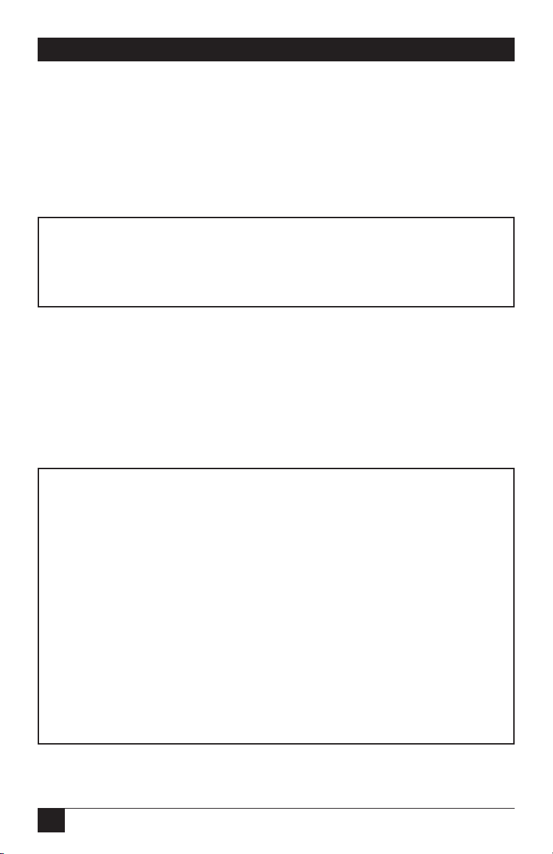
To configure the rear cards, you must set the configuration straps. Figure 19 shows
the orientation of these straps. Each strap can either be on pegs 1 and 2, or on
pegs 2 and 3. Sections 4.3.1 and 4.3.2 describe the strap locations and possible
settings for each rear card.
Figure 19. Orientation of interface card straps.
123 123 123
Page 34

31
CHAPTER 4: Configuration
4.3.1 M
ICRO
CSU/DSU DB25 R
EARSTRAPSETTINGS
Figure 20 shows strap locations for the MicroCSU/DSU DB25 Rear (DB25/RJ48S). These straps determine various grounding characteristics for the terminal
interface and twisted-pair lines.
Figure 20. DB25/RJ-48S strap locations.
Table 3 provides an overview of interface strap functions for the rear interface
cards. Following this overview is a detailed description of each strap’s function.
Strap Function Position 1 & 2 Position 2 & 3
JB3 DTE Shield (Pin 1) & FRGND Connected Open*
JB4 FRGND & SGND Connected Open*
NOTE: * indicates factory default
Table 3. Summary of strap settings
JB2
(Not Used)
JB3
(Peg 1 on top)
JB4
(Peg 1 on left)
Page 35

32
MicroCSU/DSU Cards and MicroRacks
DTE Shield (Pin 1) & FRGND (JB3)
In the connected position, this strap links DB25 pin 1 and frame ground. In the
open position, pin 1 is “lifted” from frame ground.
JB3
Position 1 & 2 = DTE Shield (Pin 1) and FRGND Connected
Position 2 & 3 = DTE Shield (Pin 1) and FRGND Not Connected
SGND & FRGND (JB4)
In the connected position, this strap links DB25 pin 7 (Signal Ground) and frame
ground. In the open position, pin 1 is “lifted” from frame ground.
JB4
Position 1 & 2 = SGND (Pin 7) and FRGND Connected
Position 2 & 3 = SGND (Pin 7) and FRGND Not Connected
4.3.2 M
ICRO
CSU/DSU V35 R
EARSTRAPSETTINGS
Figure 21 shows the strap location for the MicroCSU/DSU V35 Rear (M/34/RJ48S). This strap determines whether Signal Ground and Frame Ground will be
connected.
Figure 21. M/34/RJ-48S strap locations.
Page 36

33
CHAPTER 4: Configuration
SGND & FRGND (JB4)
In the connected position, this strap links Signal Ground and Frame Ground.
JB4
Position 1 & 2 = SGND and FRGND Connected
Position 2 & 3 = SGND and FRGND Not Connected
Page 37
34
MicroCSU/DSU Cards and MicroRacks
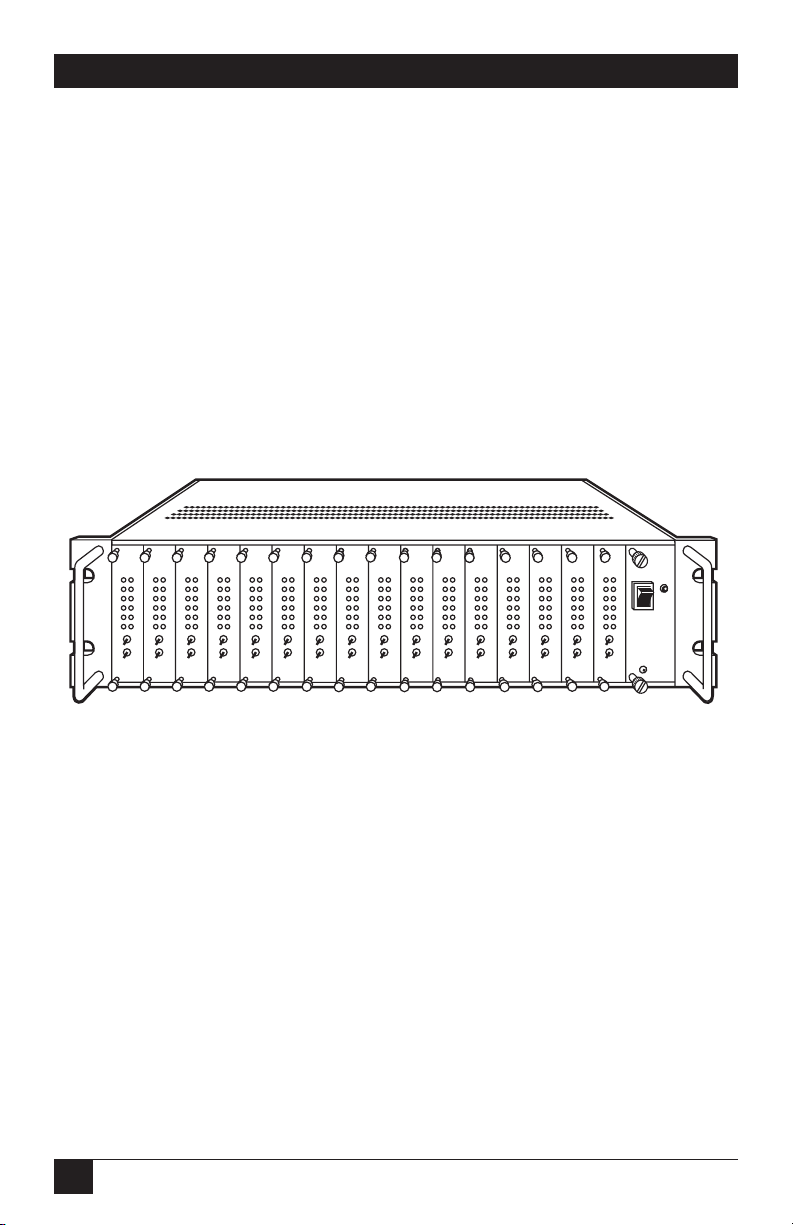
5. Installation
This chapter describes the functions of the MicroRack chassis, tells how to install
front and rear MicroCSU/DSU cards into the chassis, and provides diagrams for
wiring the interface connections correctly.
The MicroRacks come with two, four, eight, or sixteen short-range modem card
slots, plus its own power supply. Measuring only 3.5 inches high, the MicroRack
is designed to occupy only 2U in a 19-inch rack. Sturdy front handles allow the
MicroRack 16 to be extracted and transported conveniently.
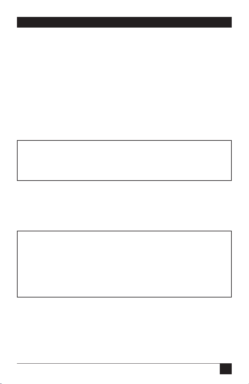
Figure 22. The MicroRack 16.
The power supply consists of two cards: a front power-supply card and the rear
power entry card. The two cards meet inside the rack chassis and plug into each
other by means of a multipin connector. Use the steps on the next page as a guide
for installing the power-supply module.
ON
OFF
Power
MicroRack System
AC Power Supply
Page 38

35
CHAPTER 5: Installation
Rear (Power Entry) Card Installation
1. Attach the ground wire using the star washer and the #6-32 nut. Use a wrench
to tighten the nut securely.
2. Slide the power entry card into the back of the chassis along the metal guide
rails provided.
3. Secure the rear card using the #4-40 metal screws provided.
CAUTION
To avoid shock, do not connect power cables until the power-supply
module is fully assembled.
Front (Power Supply) Card Installation
1. Make sure the power switch is in the OFF position.
2. Slide the power-supply card into the front of the chassis. It should meet the
rear card when it’s almost all the way into the chassis.
3. Push the front card gently into the multipin connector on the rear card.
4. Secure the front card using the thumbscrews.
Rear Card Power Connection for the AC Power Supply
The PS460A rear card is equipped with a shrouded male IEC-320 AC power
interface. This interface accepts a domestic U.S. power cord or any number
of international power cords.
DC Rear Card Power Connection
The power supply’s rear card comes equipped with a cage-clamp terminal block.
The steps below will help you install the rear card.
CAUTION
Connect the equipment to a SELV DC supply source that is electrically
isolated from the AC power sources. The DC power source should also
be reliably connected to earth ground.
Page 39

36
MicroCSU/DSU Cards and MicroRacks
1. Strip back the insulation on each of the wires about a quarter of an inch.
2. Use a small flatblade screwdriver to open the cage clamp as shown in Figure
3-2. Insert the stripped portion of the wire into the opening and remove the
screwdriver. The cage clamp will clamp the wire, producing a reliable
connection. Make sure all strands of wire are captured and that there is no
exposed wire.
3. Connect the earth ground wire to the frame ground terminal.
4. Connect the +VDC power wire to the +DC In terminal. Connect the -VDC
power wire to the -DC In terminal. The power-supply card is protected against
accidental reversal of polarity. If the DC-Input LED does not light, check the
polarity of the input wiring.
5. Connect the Alarm contacts as needed by your application.
Figure 23. Connecting bare wires to the rear power-entry card.
Replacing the Power Supply Fuse
The rack chassis power supply uses a 400 mA fuse for 120-VAC circuits, and a 200
mA fuse for 240-VAC circuits. The fuse compartment is located just below the AC
socket on the rear card. To replace the fuse, follow the steps on the next page:
1) Turn the power switch off and remove the power cord.
2) Using a small screwdriver, pop the compartment open (it will slide open
like a drawer). Depending upon the exact part used, the drawer may slide
completely out of the fuse holder or it may stop partway out.
Page 40

37
CHAPTER 5: Installation
3) Note that there are two fuses in the drawer. The front fuse is the spare,
and the rear fuse is the “active” fuse.
4) If the active fuse appears to be blown, remove it from the clips and replace it
with the spare from the front compartment. Note the size and rating of the
blown fuse before discarding it.
5) Buy a replacement fuse at an electronics store. (Note: For continued
protection against the risk of fire, replace only with the same type and
rating of fuse.)
Switching the Power Supply Between 120 and 240 Volts
The power supply module should be installed in the rack chassis before any
CSU/DSU cards. Here are the steps to select the switch for the proper voltage
level.
1) Locate the two-position switch near the back of the card. Slide the switch to
the desired voltage. (Note: The actual values on the switch may be “110/220”
or “115/230.”)
2) Verify that the existing fuse is the correct value (400 mA for the 120-volt, 200
mA for the 240-volt).
3) Connect the power supply cord.
Wiring the MicroCSU/DSU
Each of the rear interface cards compatible with the MicroCSU/DSU has one
terminal interface port and one 4-wire (twisted pair) port. For specific interface
pinouts, refer to Appendix B.
Operating the Power Supply
The AC power supply has a single power LED on the front panel, which lights
when the power switch is turned on and the unit is connected to an AC power
source.
The DC power supplies feature two front-panel LEDs that indicate the condition of
the power line. The “Power ” LED will only light when the power switch is turned
on and the low voltage AC power is available to the function cards installed in the
rack. The “DC Input” LED will light whenever a power source is present (with
correct polarity), regardless of whether or not the power switch is turned on.
Page 41

38
MicroCSU/DSU Cards and MicroRacks
6. DDS Testing
The MicroCSU/DSU offers three tests to evaluate the condition of the CSU/DSUs
and the communication link: local analog loopback testing, remote digital
loopback testing, and telco testing. This section describes how to utilize each of
these test modes.
6.1 Local Analog Loopback Testing
The Local Analog Loopback (LAL) test checks the operation of the local
MicroCSU/DSU. Any data sent to the local MicroCSU/DSU in this test mode will
be echoed (returned) back to the user device. For example, characters typed on
the keyboard of a terminal will appear on the terminal screen. To perform an
Analog Loopback test, follow these steps:
1) Activate Analog Loopback. This may be done in one of two ways: by moving
the front-panel toggle switch to Analog or by raising signal LL on the terminal
interface. Once LAL is activated, the MicroCSU/DSU transmit output is
connected to its own receiver. The “test” LED should be lit.
2) Verify that the data terminal equipment is operating properly and can be used
for a test. If a fault is indicated, call your supplier.
3) Perform a BER (bit error rate) test on each unit. If the BER test equipment
indicates no faults but the data terminal indicates a fault, follow the
manufacturer’s checkout procedures for the data terminal. Also, check the
interface cable between the terminal and the MicroCSU/DSU.
CSU/DSU
Page 42
39
CHAPTER 6: DDS Testing
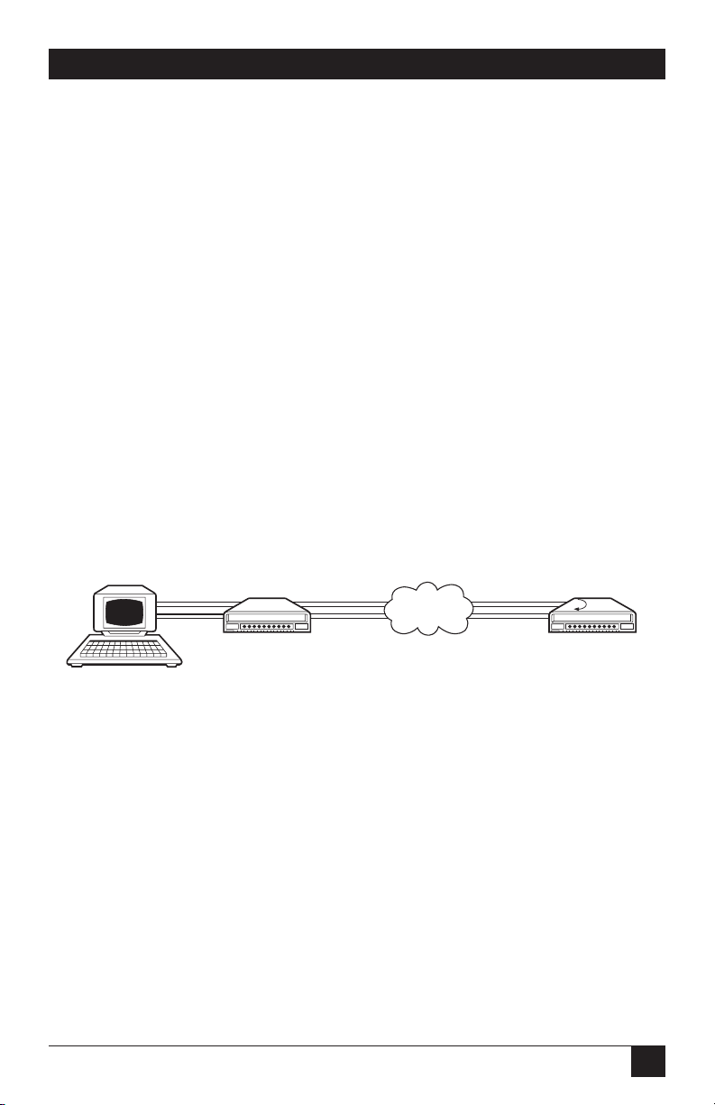
6.2 Remote Digital Loopback Testing
The Remote Digital Loopback (RDL) test checks the performance of both the
local and remote MicroCSU/DSUs, and the communication link between them.
Any characters sent to the remote MicroCSU/DSU in this test mode will be
returned back to the originating device. For example, characters typed on the
keyboard of the local terminal will appear on the local terminal screen after having
been passed to the remote MicroCSU/DSU and looped back. To perform an RDL
test, follow these steps:
1) Activate RDL. This may be done in two ways: by moving the front-panel toggle
switch to “Remote” or by raising the RL signal on the terminal interface.
2) Perform a BER (bit error rate) test on the system.
3) If the BER test equipment indicates a fault and the Local Analog Loopback
test was successful for both MicroCSU/DSU modems, you may have a problem
with the line between the CSU/DSUs. You should inspect the line for proper
connections.
DIGITAL
NETWORK
CSU/DSU
Page 43

40
MicroCSU/DSU Cards and MicroRacks
6.3 V.52 BER Test Generator
The MicroCSU/DSU has a built-in test pattern generator and detector. It can be
invoked at both ends of a link simultaneously, or it can be used with the Local
Analog or Remote Digital Loopback. The following example requires two
operators: one to initiate and monitor the test at the local MicroCSU/DSU
modem, and one at the remote MicroCSU/DSU modem. To use the V.52 BER
test by itself, both operators should simultaneously follow these steps:
1) Locate the “511/511E” toggle switch on the front panel of the
MicroCSU/DSU and move it to “511.” This activates the V.52 BER test mode
and transmits a “511” pseudorandom test pattern to the other unit. If any
errors are received, the receiving CSU/DSU’s red “Error” LED will blink
sporadically.
NOTE
For this test to function, the “511” switch on both MicroCSU/DSU
modems must be on.
2) If the test indicates no errors are present, move the V.52 toggle switch to the
“511/E” test. The 511/E test transmits the 511 pseudorandom test pattern and
periodically injects intentional errors. If the test is working properly, the
receiving CSU/DSU’s red “Error” LED will blink regularly. A successful 511/E
test will confirm that the link is in place, and that the MicroCSU/DSU’s builtin 511 generator and detector are working properly.
3) This test can be done by one operator by first activating the local analog loop
or remote digital loop.
6.4 Telco Testing
The digital service provider’s central office can perform CSU Loop and DSU Loop
diagnostic testing. These diagnostics allow the central office to evaluate circuit
operation without making visits to a customer’s premises.
Page 44

41
CHAPTER 6: DDS Testing
6.4.1 CSU L
OOP
The CSU Loop is activated when the central office reverses the DC sealing current
that flows between the TX pair and the RX pair. In this case, the MicroCSU/DSU
recognizes this and loops signals on the RX pair back to the central office on the
TX pair. While the CSU Loop is activated by the central office, the TM light is
illuminated.
6.4.2 DSU L
OOP
The DSU Loop is activated when the central office sends a DSU loop signal over
the twisted-pair wire. The MicroCSU/DSU senses this signal and loops the digital
data back to the central office. While the DSU Loop is activated, the TM light is
illuminated.
DSU CSU
DIGITAL
NETWORK
DSU CSU
DIGITAL
NETWORK
Page 45

42
MicroCSU/DSU Cards and MicroRacks
Appendix A. Cable
Recommendations
The MicroCSU/DSU has been tested using twisted-pair cable with the following
characteristics:
Wire Gauge Capacitance Resistance
19 AWG 83nf/mi or 15.72 pf/ft. 0.0163 ohms/ft.
22 AWG 83nf/mi or 15.72 pf/ft. 0.0326 ohms/ft.
24 AWG 83nf/mi or 15.72 pf/ft. 0.05165 ohms/ft.
For optimum performance from your MicroCSU/DSU, keep the following
guidelines in mind:
• Always use twisted-pair wire—this is not an option.
• Use twisted-pair wire with a capacitance of 20 pf/ft. or less.
• Avoid twisted-pair wire thinner than 26 AWG (in other words, avoid higher
AWG numbers than 26).
• Use of twisted pair with a resistance greater than the above specifications may
cause a reduction in maximum distance obtainable. Functionality should not
be affected.
• Many different environmental factors can affect the maximum distances
obtainable at a particular site
.
Page 46

43
APPENDIX B: Interface Pin Assignment
Appendix B. Interface Pin
Assignment
B.1 DDS Interface
The DDS Interface is an RJ-48S modular jack.
Pin # Signal
1 TX+
2 TX-
3 No connection
4 No connection
5 No connection
6 No connection
7 RX+
8 RX-
B.2 M/34 Connector, Terminal Interface
Pin # Signal
B SGND (Signal Ground)
C RTS
D CTS
E DSR
FCD
H DTR
L LL (Local Loop)
M TM (Test Mode)
N RL (Remote Loop)
PTD
RRD
S TD/
T RD/
Page 47

44
MicroCSU/DSU Cards and MicroRacks
M/34 Connector, Terminal Interface (continued)
U XTC
VRC
W XTC/
X RC/
YTC
AA TC/
B.3 DB25 Connector, Terminal Interface
Pins are assigned according to RS-232E and EIA-530 standards.
Pin # Signal
1 Frame Ground
2TD
3RD
4 RTS
5 CTS
6 DSR
7 SGND (Signal Ground)
8CD
9 /RC
11 /XTC
12 /TC
14 /TD
15 TC
16 /RD
17 RC
18 LL (Local Loop)
20 DTR
21 RL (Remote Loop)
24 XTC
25 TM (Test Mode)
Page 48

45
APPENDIX C: Transmitter Clock Source During Test Loops
Appendix C. Transmitter Clock
Source During Test Loops
Clock Analog Originating Receiving
Mode Normal Loop Remote Loop Remote Loop
Internal INT INT INT RC
External EXT INT EXT EXT
Network RC INT RC RC
RC = Receive Clock
 Loading...