

Page 1
MSC-6 0- CCN MSC-8 4-TCN MSC-120- CCN MSC-168- CCN
MSC-60-CNN MSC-84-TNN MSC-120-CNN MSC-168-CNN
MSC-72-CCN MSC-96-TCN MSC-144-CCN MSC-192-TCN
MSC-72-CNN MSC-96-TNN MSC-144-CNN MSC-192-TNN
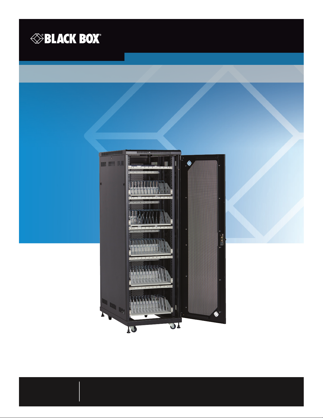
Mass Charging Cabinets
User Manual
Provide high-capacity charging and storage for your tablets or laptops.
Contact
Information
Order toll-free in the U.S. or for FREE technical support: Call 877-877-BBOX
(outside U.S. call 724-746-5500)
www.blackbox.com • info@blackbox.com
Page 2

Trademarks Used in this Manual
Trademarks Used in this Manual
Black Box and the Double Diamond logo are registered trademarks of BB Technologies, Inc.
Chromebook is a trademark of Google Inc.
iPad is a registered trademark of Apple, Inc.
UL is a registered trademark of Underwriters Laboratories.
Any other trademarks mentioned in this manual are acknowledged to be the property of the trademark owners.
Page 2
We‘re here to help! If you have any questions about your application
or our products, contact Black Box Tech Support at 877-877-2269
or go to blackbox.com and click on “Talk to Black Box.”
You’ll be live with one of our technical experts in less than 60 seconds.
877-877-2269 | blackbox.com
Page 3

FCC and IC RFI Statements
Federal Communications Commission and Industry Canada Radio Frequency Interference
Statements
This equipment generates, uses, and can radiate radio-frequency energy, and if not installed and used properly, that is, in strict
accordance with the manufacturer’s instructions, may cause inter ference to radio communication. It has been tested and found to
comply with the limits for a Class A computing device in accordance with the specifications in Subpart B of Part 15 of FCC rules,
which are designed to provide reasonable protection against such interference when the equipment is operated in a commercial
environment. Operation of this equipment in a residential area is likely to cause interference, in which case the user at his own
expense will be required to take whatever measures may be necessary to correct the interference.
Changes or modifications not expressly approved by the party responsible for compliance could void the user’s authority to
operate the equipment.
This digital apparatus does not exceed the Class A limits for radio noise emis sion from digital apparatus set out in the Radio
Interference Regulation of Industry Canada.
Le présent appareil numérique n’émet pas de bruits radioélectriques dépassant les limites applicables aux appareils numériques
de la classe A prescrites dans le Règlement sur le brouillage radioélectrique publié par Industrie Canada.
Disclaimer:
Black Box Network Services shall not be liable for damages of any kind, including, but not limited to, punitive, consequential or cost of cover damages, resulting
from any errors in the product information or specifications set forth in this document and Black Box Network Services may revise this document at any time
without notice.
877-877-2269 | blackbox.com
Page 3
Page 4

NOM Statement
Instrucciones de Seguridad
(Normas Oficiales Mexicanas Electrical Safety Statement)
1. Todas las instrucciones de seguridad y operación deberán ser leídas antes de que el aparato eléctrico sea operado.
2. Las instrucciones de seguridad y operación deberán ser guardadas para referencia futura.
3. Todas las advertencias en el aparato eléctrico y en sus instrucciones de operación deben ser respetadas.
4. Todas las instrucciones de operación y uso deben ser seguidas.
5. El aparato eléctrico no deberá ser usado cerca del agua—por ejemplo, cerca de la tina de baño, lavabo, sótano mojado o cerca
de una alberca, etc.
6. El aparato eléctrico debe ser usado únicamente con carritos o pedestales que sean recomendados por el fabricante.
7. El aparato eléctrico debe ser montado a la pared o al techo sólo como sea recomendado por el fabricante.
8. Servicio—El usuario no debe intentar dar servicio al equipo eléctrico más allá a lo descrito en las instrucciones de operación.
Todo otro servicio deberá ser referido a personal de servicio calificado.
9. El aparato eléctrico debe ser situado de tal manera que su posición no interfiera su uso. La colocación del aparato eléctrico
sobre una cama, sofá, alfombra o superficie similar puede bloquea la ventilación, no se debe colocar en libreros o gabinetes
que impidan el flujo de aire por los orificios de ventilación.
10. El equipo eléctrico deber ser situado fuera del alcance de fuentes de calor como radiadores, registros de calor, estufas u otros
aparatos (incluyendo amplificadores) que producen calor.
11. El aparato eléctrico deberá ser connectado a una fuente de poder sólo del tipo descrito en el instructivo de operación, o como
se indique en el aparato.
12. Precaución debe ser tomada de tal manera que la tierra fisica y la polarización del equipo no sea eliminada.
13. Los cables de la fuente de poder deben ser guiados de tal manera que no sean pisados ni pellizcados por objetos colocados
sobre o contra ellos, poniendo particular atención a los contactos y receptáculos donde salen del aparato.
14. El equipo eléctrico debe ser limpiado únicamente de acuerdo a las recomendaciones del fabricante.
15. En caso de existir, una antena externa deberá ser localizada lejos de las lineas de energia.
16. El cable de corriente deberá ser desconectado del cuando el equipo no sea usado por un largo periodo de tiempo.
17. Cuidado debe ser tomado de tal manera que objectos liquidos no sean derramados sobre la cubierta u orificios de ventilación.
18. Servicio por personal calificado deberá ser provisto cuando:
A: El cable de poder o el contacto ha sido dañado; u
B: Objectos han caído o líquido ha sido derramado dentro del aparato; o
C: El aparato ha sido expuesto a la lluvia; o
D: El aparato parece no operar normalmente o muestra un cambio en su desempeño; o
E: El aparato ha sido tirado o su cubierta ha sido dañada.
Page 4
877-877-2269 | blackbox.com
Page 5

Safety Instructions and Electrical Precautions
Safety Instructions aned Electrical Precautions
Please read these operating instructions carefully. They contain important advice concerning the use and safety of your Mass
Charging Cabinet. The Cabinet must only be used for its intended purpose in accordance with these operating instructions. Any
misuse of the product will void the warranty.
• The power switch must be in the “OFF” position before plugging the Cabinet into a wall receptacle.
• The Cabinet must ONLY be connected to a 120-volt AC 15- or 20-amp power supply.
• The Cabinet must only be used by adults or with adult supervision.
• Always store the power cord around the cord wraps when transporting the Cabinet.
• Never pull the Cabinet by the power cord.
• Do not plug the Cabinet in if the switch, receptacle(s), or power cord has been damaged. All electrical components on this product
must be repaired by a qualified electrician.
• Do not use an extension cord in conjunction with the Cabinet.
• Do not use liquids in or around the Cabinet environment.
• Inadequate repair can create significant hazards to users and is not covered by warranty.
• For your safety, we recommend that a qualified electrician test the circuit you will be plugging the Cabinet into. The circuit should be
checked for ground integrity and appropriate branch circuit protection.
• The Cabinet ground prong must be present for safe operation. If the plug is damaged or if the ground prong has been removed, it
should be replaced by a qualified electrician.
• The use of the Cabinet, including plugging or unplugging laptops, plugging or unplugging the Cabinet, operating the control
switch, and engaging or releasing the directional and locked casters, must be done with adult supervision.
• The Cabinet can be very heavy when fully loaded with laptops and should be moved about by persons physically able to do so.
• The Cabinet should only be used for the storage and transport of tablets, laptops, and other similar devices.
• Misuse, incorrect operation, or inadequate repair of the Cabinet will void the warranty.
877-877-2269 | blackbox.com
Page 5
Page 6

Table of Contents
Table of Contents
Trademarks Used in this Manual .................................................................................................................................................2
FCC and IC RFI Statements ......................................................................................................................................................... 3
NOM Statement .......................................................................................................................................................................4
Safety Instructions and Electrical Precautions .............................................................................................................................. 5
1. Specifications .........................................................................................................................................................................7
2. Overview............ .....................................................................................................................................................................13
2.1 Introduction ....................................................................................................................................................................13
2.2 What‘s Included ............................................................................................................................................................. 13
2.3 Cabinet Configuration Examples for Chromebook Computer and Laptop Storage and Charging ....................................13
2.3.1 MSC-60-CCN and MSC-60-CNN .......................................................................................................................13
2.3.2 MSC-72-CCN and MSC-72-CNN .......................................................................................................................15
2.4 Cabinet Configuration Examples for Tablet Storage and Charging ..................................................................................17
2.4.1 MSC-84-TCN and MSC-84-TNN ........................................................................................................................17
2.4.2 MSC-96-TCN and MSC-96-TNN ........................................................................................................................18
3. Configuration and Setup .......................................................................................................................................................20
3.1 Routing the Cable (Cabinets with Shelves SIzed for Tablets) ............................................................................................20
3.2 Fastening the Power Bricks and Routing the Cable (Cabinets with Shelves SIzed for Chromebook Computers
and Laptops) ...................................................................................................................................................................22
4. Using Your
4.1 Charging Your Computers .............................................................................................................................................23
4.2 Automated Power Controller Instructions .......................................................................................................................23
5. Troubleshooting ......................................................................................................................................................................24
5.1 Contacting Black Box ......................................................................................................................................................24
5.2 Shipping and Packaging ..................................................................................................................................................24
Mass Charging Cabinet ........................................................................................................................................23
Page 6
877-877-2269 | blackbox.com
Page 7
Chapter 1: Specifications
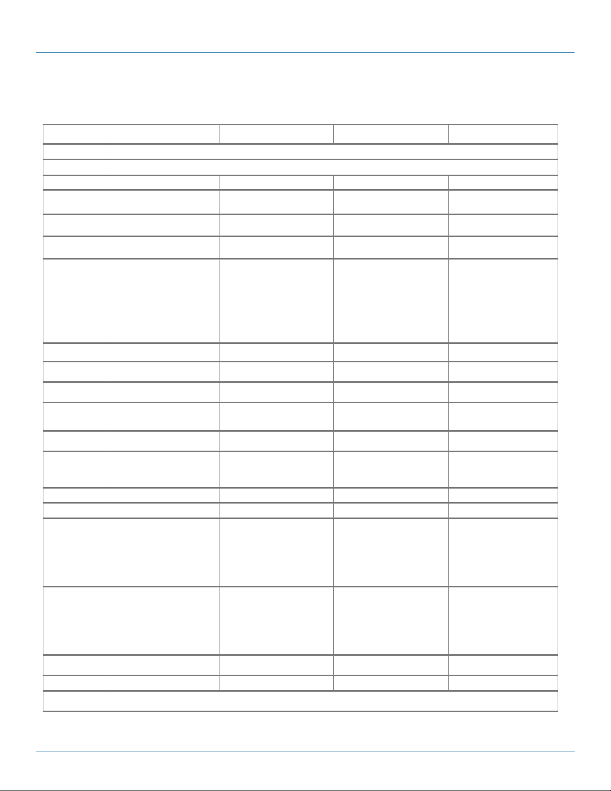
1. Specifications
Mass Charging Cabinets for Chromebook™ Computers and Laptops Specifications
Part # MSC-60-CCN MSC-60-CNN M SC-7 2-CCN MSC -72-CNN
Approvals UL
Assembled Yes
Cable Acces s Built-in knockout panels Built-in knockout panels Built-in knockout panels Built-in knockout panels
Cable Management Yes No Ye s No
Casters 2.5" casters and l eg levelers 2.5” casters and leg levele rs 2.5” casters and leg levele rs 2.5” casters and leg levele rs
Color Black Black Black Black
Components
Included
Construction 16-gauge steel ca binet and do ors 16 -gauge steel cabinet and doors 16-gauge steel cabinet and doors 16-gauge steel cabine t and doors
Device Capacity ( 60) Chromebook
Doors Mesh front door and
Locking Key: Lock ing front door and rear access
Power Management
Dividers
Power (Input) 110-120 VAC (6-foot attached power
Power Outlet 72, via (6) 12-outlet power strips 72, via (6) 12-outlet power strips 84, via (7) 12-outlet power strips 84, via (7) 12-outlet power strips
On/ Off Switch Ye s Ye s Yes Yes
Dimensions (Cabinet) Interior:
Dimensions (Slot) With cable management:
Shipping Carton
Dimensions
Weight Capacity 2250 lb. (1020.6 kg) 2250 lb. (1020.6 kg) 2250 lb. (1020.6 kg) 2250 lb. (1020.6 kg)
Warranty Cabinet: Lifetime;
• (1) Mass Storage and Charging
Cabinet (RM2520A)
• (5) Medium Shelve s (UCCSHELFM-12)
• (5) Front cable management bar s
• (5) Rear cable management bar s
• (6) 12-outlet power strips
(P DU BH 12-S15 -120 V- R3 )
• (1) Automated Power Controller
(CA RT TIM ER1)
• (1)
12-ft. (3.6- m) Power Cord
™
(12) per shelf
split rear m esh door
panel for easy cable management
(keyed differently)
cord includ ed), 50 /60 Hz,
Plu g t yp e: 5-15P,
Outle t t yp e: 5 -15R
66.5"H (38U) x 21.3"W x 38.5"D
(168.9 x 54.1 x 97.8 cm);
Exterior:
70.7"H (38U) x 23.6"W x 39.4"D
(179.6 x 59.9 x 100.1 cm)
NOTE: Exterior hei ght does not include
casters.
10.5”H x 1.12”W x 15”D
(26.67 x 2.8 4 x 38.1 cm)
NOTE: This can be changed by using
the zero U cab le manager s (if
available for the shelf ) or by
raising the position of the cable
management bar.
80"H x 25"W x 40.5"D
(203.2 x 63.5 x 102.87 cm)
(U CCPC)
computers/laptops,
65 65 78 78
• (1) Mass Storage and Charging Cabinet
(RM2520 A)
• (5) Medium Shelve s (UCCSHELFM-12)
• (5) Rear cable management bar s
• (6) 12-outlet power strips
(P DU BH 12-S15 -120 V- R3 )
• (1) Automated Power Controller
(CA RT TIM ER1)
• (1)
12-ft. (3.6- m) Power Cord
(60) Chromebo ok™ computers/laptops,
Key: Lock ing front door and rear access
110-120 VAC (6-foot attac hed power
cord includ ed), 50 /60 Hz,
Plu g t yp e: 5-15P,
Outle t t yp e: 5 -15R
Interior:
66.5”H (38U ) x 21.3”W x 38.5”D
(168.9 x 54.1 x 97.8 cm);
Exterior:
70.7”H (38U) x 23.5”W x 39.4”D
(179.6 x 59.9 x 100.1 cm)
NOTE: Exterior hei ght does not include
Without cable management:
12.25”H x 1.12”W x 15”D
(31.11 x 2. 84 x 38.1 cm)
(12) per shelf
Mesh front door and
split rear m esh door
panel for easy cable management
(keyed differently)
casters.
80"H x 25"W x 40.5"D
(203.2 x 63.5 x 102.8 cm)
®
approved power strips
• (1) Mass Storage and Charging Cabinet
(RM25 40A)
• (6) M edium Shelves (UCCSHELFM-12)
• (6) Front cable management ba rs
• (6) Rear cable management ba rs
• (7) 12-outlet power strips
(P DU BH 12-S15 -120 V- R3 )
• (1) Automated Power Controller
(U CCPC)
Electronics: 3 ye ars
(CA RT TIM ER1)
• (1)
(72) Chromebook™ computers/laptops, ,
Key: Lock ing front door and rear access
110-120 VAC (6-foot attac hed power
cord includ ed), 50 /60 Hz,
Plu g t yp e: 5-15P,
Outle t t yp e: 5 -15R
Interior:
73.5”H (42U) x 21.3”W x 38.5”D
(186.7 x 54.1 x 97.8 cm);
Exterior:
77.6”H (42U) x 23.5”W x 39.4”D
(197.1 x 59.9 x 100.1 cm)
NOTE: Exterior hei ght does not include
With cable management:
10.5”H x 1.12”W x 15”D
(26.67 x 2.8 4 x 38.1 cm)
NOTE: This can be changed by using the
12-ft. (3.6- m) Power Cord
(12) per shelf
Mesh front door and
locking split rear mesh door
panel for easy cable management
(keyed differently)
casters.
zero U cable managers ( if available for the shelf) or by
raising the position of the cable
management bar.
87"H x 25.5"W x 40.5"D
(220.9 x 64.7 x 102.8 cm )
(U CCPC)
• (1) Mass Storage and Charging
Cabinet ( RM254 0A)
• (6) M edium Shelves (UCCSHELFM-12)
• (6) Rear cable management ba rs
• (7) 12-outlet power strips
(P DU BH 12-S15 -120 V- R3 )
• (1) Automated Power Controller
(CA RT TIM ER1)
• (1)
12-ft. (3.6- m) Power Cord
(72) Chromebook™ computers/laptops,
Key: Lock ing front door and rear access
110-120 VAC (6-foot attac hed power
cord includ ed), 50 /60 Hz,
Plu g t yp e: 5-15P,
Outle t t yp e: 5 -15R
Interior:
73.5”H (42U) x 21.3”W x 38.5”D
(186.7 x 54.1 x 97.8 cm);
Exterior:
77.6”H (42U) x 23.5”W x 39.4”D
(197.1 x 59.9 x 100.1 cm)
NOTE: Exterior hei ght does not include
Without cable management:
12.25"H x 1.12"W x 15"D
(31.11 x 2. 84 x 38.1 cm)
, (12) per shelf
Mesh front door and
locking split rear mesh door
panel for easy cable management
(keyed differently)
casters.
87"H x 25.5"W x 40.5"D
(220.9 x 64.7 x 102.8 cm )
(U CCPC)
877-877-2269 | blackbox.com
Page 7
Page 8
Chapter 1: Specifications
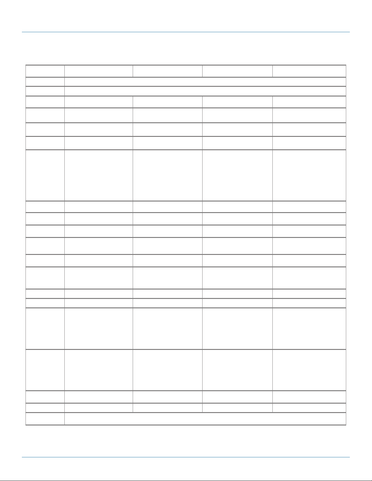
Mass Charging Cabinets for Chromebook™ Computers and Laptops Specifications (continued)
Part # MSC-120 -CCN M SC-120 -CNN MSC-144-CCN MSC-144-CNN
Approvals UL
Assembled Yes
Cable Acces s Built-in knockout panels Built-in knockout panels Built-in knockout panels Built-in knockout panels
Cable Management Yes No Ye s No
Casters 2.5" casters and l eg levelers 2.5” casters and leg levele rs 2.5” casters and leg levele rs 2.5” caste rs and leg levelers
Color Black Black Black Black
Components
Included
Construction 16-gauge steel ca binet and do ors 16 -gauge steel cabinet and doors 16- gauge steel cabinet a nd doors 16-gauge steel ca binet and do ors
Device Capacity (120) Chromebook
Doors Mesh front door and
Locking Key: Lock ing front door and rear access
Power Management
Dividers
Power (Input) 110-120 VAC (6-foot attached power
Power Outlet 120, via (10) 12-outlet power strips 120, via (10) 12-outlet power strips 144, via (12) 12-outlet power strips 144, via (12) 12-outlet power strips
On/ Off Switch Ye s Ye s Yes Yes
Dimensions (Cabinet) Interior:
Dimensions (Slot) With cable management:
Shipping Carton
Dimensions
Weight Capacity 2250 lb. (1020.6 kg) 2250 lb. (1020.6 kg) 2200 lb. (997.9 kg) 2200 lb. (1020.6 kg)
Warranty Cabinet: Lifetime;
• (1) Mass Storage and Charging
Cabinet (RM2520A)
• (10) Medium Shelves ( UCCSHELFM -12)
• (10) Front cable managem ent bars
• (10) Rear cable managem ent bars
• (10) 12-outlet power strips
(P DU BH 12-S15 -120 V- R3 )
• (2) Automated Power Controllers
(CA RT TIM ER1)
• (1)
12-ft. (3.6- m) Power Cord
(12) per shelf
split rear m esh door
panel for easy cable management
(keyed differently)
130 130 156 15 6
cord includ ed), 50 /60 Hz,
Plu g t yp e: 5-15P,
Outle t t yp e: 5 -15R
66.5"H (38U) x 21.3"W x 38.5"D
(168.9 x 54.1 x 97.8 cm);
Exterior:
70.7"H (38U) x 23.6"W x 39.4"D
(179.6 x 59.9 x 100.1 cm)
NOTE: Exterior hei ght does not include
casters.
10.5”H x 1.12”W x 15”D
(26.67 x 2.8 4 x 38.1 cm)
NOTE: This can be changed by using
the zero U cab le manager s (if
available for the shelf ) or by
raising the position of the cable
management bar.
80"H x 25"W x 40.5"D
(203.2 x 63.5 x 102.87 cm)
(U CCPC)
™
computers/laptops,
• (1) Mass Storage and Charging Cabinet
(RM2520 A)
• (10) Medium Shelves ( UCCSHELFM -12)
• (10) Rear cable managem ent bars
• (10) 12-outlet power strips
(P DU BH 12-S15 -120 V- R3 )
• (2) Automated Power Controllers
(CA RT TIM ER1)
• (1)
12-ft. (3.6- m) Power Cord
(120) Chromebook™ computers/laptops,
Key: Lock ing front door and rear access
110-120 VAC (6-foot attac hed power
cord includ ed), 50 /60 Hz,
Plu g t yp e: 5-15P,
Outle t t yp e: 5 -15R
Interior:
66.5”H (38U ) x 21.3”W x 38.5”D
(168.9 x 54.1 x 97.8 cm);
Exterior:
70.7”H (38U) x 23.5”W x 39.4”D
(179.6 x 59.9 x 100.1 cm)
NOTE: Exterior hei ght does not include
Without cable management:
12.25”H x 1.12”W x 15”D
(31.11 x 2. 84 x 38.1 cm)
(12) per shelf
Mesh front door and
split rear m esh door
panel for easy cable management
(keyed differently)
casters.
80"H x 25"W x 40.5"D
(203.2 x 63.5 x 102.8 cm)
®
approved power strips
• (1) Mass Storage and Charging Cabinet
(RM26 40A)
• (12) Medium Shel ves (UCCSHELFM-12)
• (12) Front cable management bars
• (12) Rear cable management bars
• (12) 12-outlet power strips
(P DU BH 12-S15 -120 V- R3 )
• (2) Automated Power Controllers
(U CCPC)
(CA RT TIM ER1)
• (1)
(144) Chromebook™ computers/laptops, ,
110-120 VAC (6-foot attac hed power
cord includ ed), 50 /60 Hz,
Plu g t yp e: 5-15P,
Outle t t yp e: 5 -15R
Interior:
73.5”H (42U) x 21.3”W x 41.7”D
(186.7 x 54.1 x 105.9 cm);
Exterior:
77.6”H (42U) x 24”W x 43.5”D
(197.1 x 61 x 110.5 cm)
NOTE: Exterior hei ght does not include
With cable management:
10.5”H x 1.12”W x 15”D
(26.67 x 2.8 4 x 38.1 cm)
NOTE: This can be changed by using the
Electronics: 3 ye ars
12-ft. (3.6- m) Power Cord
(12) per shelf
Mesh front door and
locking split rear mesh door
Key: Lock ing front door and rear access
panel for easy cable management
(keyed differently)
casters.
zero U cable managers ( if available for the shelf) or by
raising the position of the cable
management bar.
88"H x 25"W x 46"D
(223.5 x 63.5 x 116.8 cm)
(U CCPC)
• (1) Mass Storage and Charging Cabinet
(RM26 40A)
• (12) Medium Shel ves (UCCSHELFM-12)
• (12) Rear cable management bars
• (12) 12-outlet power strips
(P DU BH 12-S15 -120 V- R3 )
• (2) Automated Power Controllers
(CA RT TIM ER1)
• (1)
12-ft. (3.6- m) Power Cord
(144) Chromebook™ computers/laptops,
Key: Lock ing front door and rear access
panel for ea sy cable management ( keyed
110-120 VAC (6-foot attac hed power co rd
included), 50 /60 Hz,
Plu g t yp e: 5-15P,
Outle t t yp e: 5 -15R
Interior:
73.5”H (42U) x 21.3”W x 41.7”D
(186.7 x 54.1 x 105.9 cm);
Exterior:
77.6”H (42U) x 24”W x 43.5”D
(197.1 x 61 x 110.5 cm)
NOTE: Exterior hei ght does not include cast-
Without cable management:
12.25"H x 1.12"W x 15"D
(31.11 x 2. 84 x 38.1 cm)
(12) per shelf
Mesh front door and
locking split rear mesh door
differently)
ers.
88"H x 25"W x 46"D
(223.5 x 63.5 x 116.8 cm)
(U CCPC)
Page 8
877-877-2269 | blackbox.com
Page 9
Chapter 1: Specifications
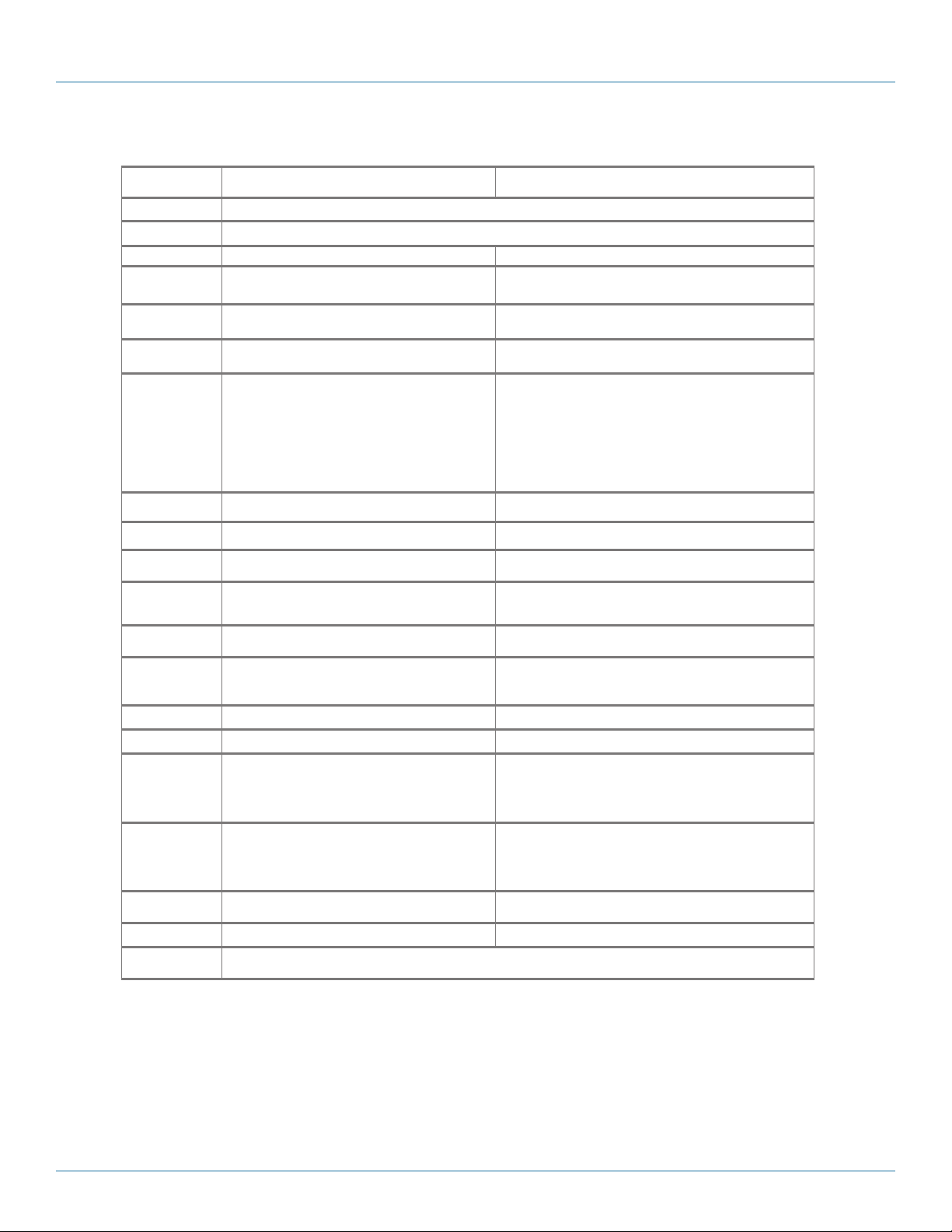
Mass Charging Cabinets for Chromebook™ Computers and Laptops Specifications (continued)
Part # MSC-16 8- CCN MSC-16 8- CNN
Approvals UL
Assembled Yes
Cable Acces s Built-in knockout panels Built-in knockout panels
Cable Management Yes No
Casters 2.5” casters and leg levele rs 2.5” casters and leg levele rs
Color Black Black
Components
Included
Construction 16-gauge steel ca binet and do ors 16-gaug e steel cabinet and doors
Device Capacity (168) Chromebook
Doors Mesh front door and
Locking Key: Locking front door a nd rear acces s panel for easy cable
Power Management
Dividers
Power (Input) 110-120 VAC (6-foot attached power cord included), 50/60 Hz,
Power Outlet 144, via (12) 12-outlet power strips 144, via (12) 12-outlet power strips
On/ Off Switch Ye s Ye s
Dimensions (Cabinet) Interior:
Dimensions (Slot) With cable management:
Shipping Carton
Dimensions
Weight Capacity 2200 lb. (997.9 kg) 2200 lb. (1020.6 kg)
Warranty Cabinet: Lifetime;
• (1) Mass Storage and Charging Cabinet (RM2640A)
• (14) Medium Sh elves (UCCSHELFM-12)
• (14) Front cable management bars
• (14) Rear cable management bars
• (14) 12-outlet power strips
(P DU BH 12-S15 -120 V- R3 )
• (2) Automated Power Controllers
(CA RT TIM ER1)
• (1)
12-ft. (3.6- m) Power Cord
Plu g t yp e: 5-15P,
Outle t t yp e: 5 -15R
73.5”H (42U) x 21.3”W x 41.7”D (186.7 x 54.1 x 105.9 cm);
Exterior:
77.6”H (42U) x 24”W x 43.5”D (197.1 x 61 x 110.5 cm)
NOTE: Exterior hei ght does not include caste rs.
10.5”H x 1.12”W x 15”D (26.67 x 2.8 4 x 38.1 cm)
NOTE: This can be changed by using the zero U cable manage rs
(if avail able for the shelf) or by
raising the p osition of the cable manage ment bar.
88"H x 25"W x 46"D (223.5 x 63.5 x 116.8 cm) 88"H x 25"W x 46"D (223.5 x 63.5 x 116.8 cm)
(U CCPC)
™
computers/laptops, , (12) per shelf (168) Chromebook™ computers/laptops, (12) per shelf
locking split rear mesh door
management
(keyed differently)
182 182
®
approved power strips
• (1) Mass Storage and Charging Cabinet (RM2640A)
• (14) Medium Sh elves (UCCSHELFM-12)
• (14) Rear cable management bars
• (14) 12-outlet power strips
(P DU BH 12-S15 -120 V- R3 )
• (2) Automated Power Controllers
(CA RT TIM ER1)
• (1)
12-ft. (3.6- m) Power Cord
Key: Lock ing front door and rear access panel for easy cable m anagement
110-120 VAC (6-foot attac hed power co rd included ), 50 /60 Hz,
Plu g t yp e: 5-15P,
Outle t t yp e: 5 -15R
Interior:
73.5”H (42U) x 21.3”W x 41.7”D (186.7 x 54.1 x 105.9 cm);
Exterior:
77.6”H (42U) x 24”W x 43.5”D (197.1 x 61 x 110.5 cm)
NOTE: Exterior hei ght does not include caste rs.
Without cable management:
12.25"H x 1.12"W x 15"D
(31.11 x 2. 84 x 38.1 cm)
Electronics: 3 ye ars
(U CCPC)
Mesh front door and
locking split rear mesh door
(keyed differently)
877-877-2269 | blackbox.com
Page 9
Page 10

Chapter 1: Specifications
Mass Charging Cabinets for Tablets Specifications
Part # MSC -8 4-TC N MSC-84-TNN MSC -96 -TCN MSC-96-TNN
Approvals UL
Assembled Yes
Cable Acces s Built-in knockout panels Built-in knockout panels Built-in knockout panels Built-in knockout panels
Cable Management Yes No Ye s No
Casters 2.5" casters and l eg levelers 2.5” casters and leg levele rs 2.5” casters and leg levele rs 2.5” casters and leg levele rs
Color Black Black Black Black
Components
Included
Construction 16-gauge steel ca binet and do ors 16 -gauge steel cabinet and doors 16- gauge steel cabinet a nd doors 16-gauge s teel cabinet and door s
Device Capacity (84) tablets, (12) per shelf (84 ) tablet s, (12) per shelf (96) tablets, (12) per shelf (96 ) tablets, (12) per shelf
Doors Mesh front door and
Locking Key: Lock ing front door and rear access
Power Management
Dividers
Power (Input) 110-120 VAC (6-foot attached power
Power Outlet 96, via (8) 12-outlet power strips 96, via (8) 12-outlet power strips 108, via (9) 12-outlet power strips 108, via (9) 12-outlet power strips
On/ Off Switch Ye s Ye s Yes Yes
Dimensions (Cabinet) Interior:
Dimensions (Slot) With cable management:
Shipping Carton
Dimensions
Weight Capacity 2250 lb. (1020.6 kg) 2250 lb. (1020.6 kg) 2250 lb. (1020.6 kg) 2250 lb. (1020.6 kg)
Warranty Cabinet: Lifetime;
• (1) Mass Storage and Charging
Cabinet (RM2520A)
• (7) Small Shelves (UCCSHELFS-12)
• (7) Front cable management bars
• (7) Rear cable management bars
• (8) 12-outlet power strips
(P DU BH 12-S15 -120 V- R3 )
split rear m esh door
panel for easy cable management
(keyed differently)
91 91 105 105
cord includ ed), 50 /60 Hz,
Plu g t yp e: 5-15P,
Outle t t yp e: 5 -15R
66.5"H (38U) x 21.3"W x 38.5"D
(168.9 x 54.1 x 97.8 cm);
Exterior:
70.7"H (38U) x 23.6"W x 39.4"D
(179.6 x 59.9 x 100.1 cm)
NOTE: Exterior hei ght does not include
casters.
Small: 7"H x x 1.12"W x x 10"D
(17.78 x 2.84 x 25.4 cm )
NOTE: This can be changed by using
the zero U cab le manager s (if
available for the shelf ) or by
raising the position of the cable
management bar.
80"H x 25"W x 40.5"D
(203.2 x 63.5 x 102.87 cm)
• (1) Mass Storage and Charging Cabinet
(RM2520 A)
• (7) Small Shelves (UCCSHELFS-12)
• (7) Rear cable management bars
• (8) 12-outlet power strips
(P DU BH 12-S15 -120 V- R3 )
Mesh front door and
split rear m esh door
Key: Lock ing front door and rear access
panel for easy cable management
(keyed differently)
110-120 VAC (6-foot attac hed power
cord includ ed), 50 /60 Hz,
Plu g t yp e: 5-15P,
Outle t t yp e: 5 -15R
Interior:
66.5”H (38U ) x 21.3”W x 38.5”D
(168.9 x 54.1 x 97.8 cm);
Exterior:
70.7”H (38U) x 23.5”W x 39.4”D
(179.6 x 59.9 x 100.1 cm)
NOTE: Exterior hei ght does not include
casters.
Without cable management:
Small: 8.75"H x 1.12"W x 10"D
(22.227 x 2.8 4 x 25.4 cm)
80"H x 25"W x 40.5"D
(203.2 x 63.5 x 102.8 cm)
®
approved power strips
• (1) Mass Storage and Charging Cabinet
(RM25 40A)
• (8) Small Shelve s (UCCSHELFS-12)
• (8) Front cable ma nagement bars
• (8) R ear cable ma nagement bars
• (9) 12-outlet power strips
(P DU BH 12-S15 -120 V- R3 )
Key: Lock ing front door and rear access
panel for easy cable management
110-120 VAC (6-foot attac hed power
cord includ ed), 50 /60 Hz,
Plu g t yp e: 5-15P,
Outle t t yp e: 5 -15R
Interior:
73.5”H (42U) x 21.3”W x 38.5”D
(186.7 x 54.1 x 97.8 cm);
Exterior:
77.6”H (42U) x 23.5”W x 39.4”D
(197.1 x 59.9 x 100.1 cm)
NOTE: Exterior hei ght does not include
With cable management:
Small: 7”H x x 1.12”W x x 10”D
(17.78 x 2.84 x 25.4 cm );
NOTE: This can be changed by using the
Electronics: 3 ye ars
Mesh front door and
locking split rear mesh door
(keyed differently)
casters.
zero U cable managers (if available
for the shelf) or by
raising the position of the cable
management bar.
87"H x 25.5"W x 40.5"D
(220.9 x 64.7 x 102.8 cm )
• (1) Mass Storage and Charging
Cabinet ( RM254 0A)
• (8) Small Shelve s (UCCSHELFS-12)
• (8) R ear cable ma nagement bars
• (9) 12-outlet power strips
(P DU BH 12-S15 -120 V- R3 )
Mesh front door and
locking split rear mesh door
Key: Lock ing front door and rear access
panel for easy cable management
(keyed differently)
110-120 VAC (6-foot attac hed power
cord includ ed), 50 /60 Hz,
Plu g t yp e: 5-15P,
Outle t t yp e: 5 -15R
Interior:
73.5”H (42U) x 21.3”W x 38.5”D
(186.7 x 54.1 x 97.8 cm);
Exterior:
77.6”H (42U) x 23.5”W x 39.4”D
(197.1 x 59.9 x 100.1 cm)
NOTE: Exterior hei ght does not include
casters.
Without cable management:
Small: 8.75”H x 1.12”W x 10”D
(22.227 x 2.8 4 x 25.4 cm)
87"H x 25.5"W x 40.5"D
(220.9 x 64.7 x 102.8 cm )
Page 10
877-877-2269 | blackbox.com
Page 11
Mass Charging Cabinets for Tablets Specifications (continued)
Part # MSC-192 -TCN MSC-192-TNN
Chapter 1: Specifications
Approvals UL
Assembled Yes
Cable Acces s Built-in knockout panels Built-in knockout panels
Cable Management Yes No
Casters 2.5" casters and leg levelers 2.5” casters and leg levele rs
Color Black Black
Components
Included
Construction 16-gauge steel ca binet and do ors 16-gaug e steel cabinet and do ors
Device Capacity (192) tablets, (12) per s helf (192) tablets, (12) per shelf
Doors M esh front do or and
Locking Key: Locking front door and rear acces s panel for ea sy cable
Power Management
Dividers
Power (Input) 110-120 VAC (6-foot attached power cord included), 50/60 Hz,
Power Outlet 96, via (8) 12-outlet power strips 96, via (8 ) 12-outlet power strips
On/ Off Switch Yes Yes
Dimensions (Cabinet) Interior:
Dimensions (Slot) With cable management:
Shipping Carton
Dimensions
Weight Capacity 2250 lb. (1020.6 kg) 2250 lb. (1020.6 kg)
Warranty Cabinet: Lifetime;
• (1) Mass Storage and Charging Cabinet (RM2540A)
• (16) Small Shelves (UCCSHELFS-12)
• (16) Front cable management bars
• (16) Rear cable management bars
• (16) 12-outlet power strips (PDUBH12-S15-120V-R3)
split rear m esh door
management (keyed differently)
208 208
Plu g t yp e: 5-15P,
Outle t t yp e: 5 -15R
73.5"H (42U) x 21.3"W x 38.5"D (186.7 x 54.1 x 97.8 cm);
Exterior:
77.6"H (42U) x 23.6"W x 39.4"D (197.1 x 59.9 x 100.1 cm)
NOTE: Exterior hei ght does not include caste rs.
Small: 7"H x x 1.12"W x x 10"D (17.78 x 2.84 x 25.4 cm )
NOTE: This can be changed by using the zero U cable
manager s (if available for the shelf) or by raising the
position of t he cable mana gement bar.
80"H x 25"W x 40.5"D (203.2 x 63.5 x 102.87 cm) 80"H x 25"W x 40.5"D (203.2 x 63.5 x 102.87 cm)
®
approved power strips
• (1) Mass Storage and Charging Cabinet (RM2540A)
• (16) Small Shelves (UCCSHELFS-12)
• (16) Rear cable management bars
• (16) 12-outlet power strips (PDUBH12-S15-120V-R3)
Mesh front door and
split rear m esh door
Key: Lock ing front door and rear access panel for easy cable m anagement
110-120 VAC (6-foot attac hed power co rd included ), 50 /60 Hz,
Plu g t yp e: 5-15P,
Outle t t yp e: 5 -15R
Interior:
73.5"H (42U) x 21.3"W x 38.5"D (186.7 x 54.1 x 97.8 cm);
Exterior:
77.6"H (42U) x 23.6"W x 39.4"D (197.1 x 59.9 x 100.1 cm)
NOTE: Exterior hei ght does not include caste rs.
Without cable management:
Small: 8.75"H x 1.12"W x 10"D (22.227 x 2.84 x 25. 4 cm)
Electronics: 3 ye ars
(keyed differently)
877-877-2269 | blackbox.com
Pa g e 11
Page 12

Chapter 1: Specifications
Mass Charging Cabinets Accessories Specifications
Part Nu mber Accessor y Specs
UCCD IV IDER -S PVC-Coated Shelf D ivider for MSC-84 and MSC-
UCCLI NE R-S -12 Padded Shelf Liner for MSC-84 and MSC-96 Series
UCCD IV IDER -M L PVC-Coated Shelf Divi der for MSC-60 and MSC-72
UCCLI NE R- M-12 Padded Shelf Lin er for MSC-60 and MSC-72 Series
UCCSY NC15 15-Unit Cambrionix Sy ncing Module
UCCSY NC15 -P Syncing M odule Power Supply
SMMB Syncing Module Mounting Bracket
UCCP C 12-ft. (3.6- m) Power Cord
96 Series
Series
Construc tion: P VC coated ste el;
Dimensions: 4.25"H x 8.45"D (10.79 x 21.46 cm);
Environmental : Indoor;
Finish: Smooth black semi-gloss PVC
Construction: Polyurethane foam;
Dimensions: 9.8"H x 17.5"W x 0.08"D (24.8 x 44.5 x 0.20 c m);
Environmental : Indoor
Finish: Black semi-gloss w ith a basket-weave texture;
Storage positions: 12;
Slot size: 1" (2.5 cm);
Weight: 0.02 lb. (0.01 kg)
Construc tion: P VC coated ste el;
Dimensions: 6"H x 12.25"D (15.24 x 31.11 cm);
Environmental : Indoor;
Finish: Smooth black semi-gloss PVC;
Construction: Polyurethane foam;
Dimensions: 15"H x 17.5"W x 0.0 8"D (38.1 x 44.5 x 0.20 cm);
Environmental : Indoor
Finish: Black semi-gloss w ith a basket-weave texture;
Storage positions: 12;
Slot size: 1" (2.5 cm);
Weight: 0.02 lb. (0.01 kg)
Physical :
Connecto rs: Inpu t: (1) 4-pin mini DIN ;
Output : (1) USB Type A male;
Construction: Plastic outer housing;
Dimensions: 1.75"H x 7.75"W x 3"D (4.45 x 19.69 x 7.62 cm);
Environmental : Indoor;
Finish: L ight gray /white sm ooth and glo ssy plastic outer housing;
Weight: 0.55 lb. (0.25 kg) ;
Electr ical (Sync and Charge unit ):
Current per port: 2.1 A max.;
Input Volt age: 12 VDC;
Input Current: 11.25 A;
Output Current: 2.1 A per port;
Output Voltage: 5. 2 VDC per port;
Electr ical (US B cord):
Connecto rs: Inpu t: (1) USB Type A male ;
Output : (1) USB Type A male;
Length : 40" (101.6 cm);
Ratings : 30 VDC @ 176° F (80° C);
Weight: 0.09 lb. (0.0 4 kg)
Physical:
Construction: Plastic outer housing;
Dimensions: 1.75"H x 3.5"W x 7.75"D (4.45 x 8 .89 x 19.68 cm) ;
Environmental : Indoor;
Finish: Matte black;
Power Cord Le ngth: 3.0 -ft. (0.9-m );
Weight: 2.2 lb. (1 kg);
Electrical:
Connecto rs: Inpu t: (1) C14;
Output : (1) 4-pin mini-DI N;
Current: Input: 2.5 A;
Output : 15 A;
Volta ge:
Input: 10 0–240 VAC, 50 –60 Hz;
Output : 12 VDC;
Power transformer Ra tings: CE, cU L, TUV, FCC Part 15;
Power Cord Ratings: 30 -VDC, 176° F (80° C), V W-1, 14Ga, RU E323326
Construction: Steel;
Dimensions: 3.5"H x 19"W x 1.25"D (8.89 x 48.26 x 3.17 cm);
Environmental : Indoor;
Finish: SMMB: light gray powde r coat (Pantone Cool Gray SC);
Hook and L oop: Black;
Weight: 2 lb. ( 0.9 kg)
Connectors: (1) right-angle NEMA 5-15P;
(1 ) I EC- 60 32 0 -C 13 ;
Length : 12 ft. (3.75 m);
Rating: 125 VAC, 15 A;
Standards: UL
Wire Type: S JTW 14 /3
®
listed;
Page 12
877-877-2269 | blackbox.com
Page 13

Chapter 2: Overview
2. Overview
2.1 Introduction
Charge, store, and secure 60–192 devices in a single cabinet (instead of using multiple carts to store the same amount of devices). These
cabinets give you high-capacity charging in a comparatively small footprint (similar footprint to most large carts). Use the cabinets for
stationary storage of large numbers of tablets/Chromebooks/laptops for charging.
To protect your devices from scratching, order rubber-coated dividers. To reduce device wear and tear, order a padded shelf liner.
To manage and update multiple tablets at one time, order a 15-unit Cambrionix syncing module.
Other custom options include network management switches and patch cables for updating and managing Chromebook
and laptops.
Please read these operating instructions carefully. They contain important advice concerning the use and safety of your cabinet. This
cabinet must only be used for its intended purpose in accordance with these operating instructions.
2.2 What‘s Included
For a complete list of what's included with each cabinet, refer to the Specifications charts on pages 7–8 of this manual.
™
computers
2.3 Cabinet Configuration Examples for Chromebook Computer/Laptop Storage and Charging
2.3.1 MSC-60-CCN and MSC-60-CNN
Figure 2-1. Front and back of MSC-60-CCN or MSC-60-CNN cabinet, doors closed.
877-877-2269 | blackbox.com
Page 13
Page 14

Chapter 2: Overview
.
Figure 2-2. Front and back of MSC-60-CCN or MSC-60-CNN cabinet, doors open.
Figure 2-3. Front of MSC-60-CCN showing front cable management bars.
NOTE: The MSC-60-CNN does not have the optional front cable management bars installed. Otherwise, the MSC-60-CCN and
MSC-60-CNN are physically the same. Both models have rear cable management.
Page 14
877-877-2269 | blackbox.com
Page 15
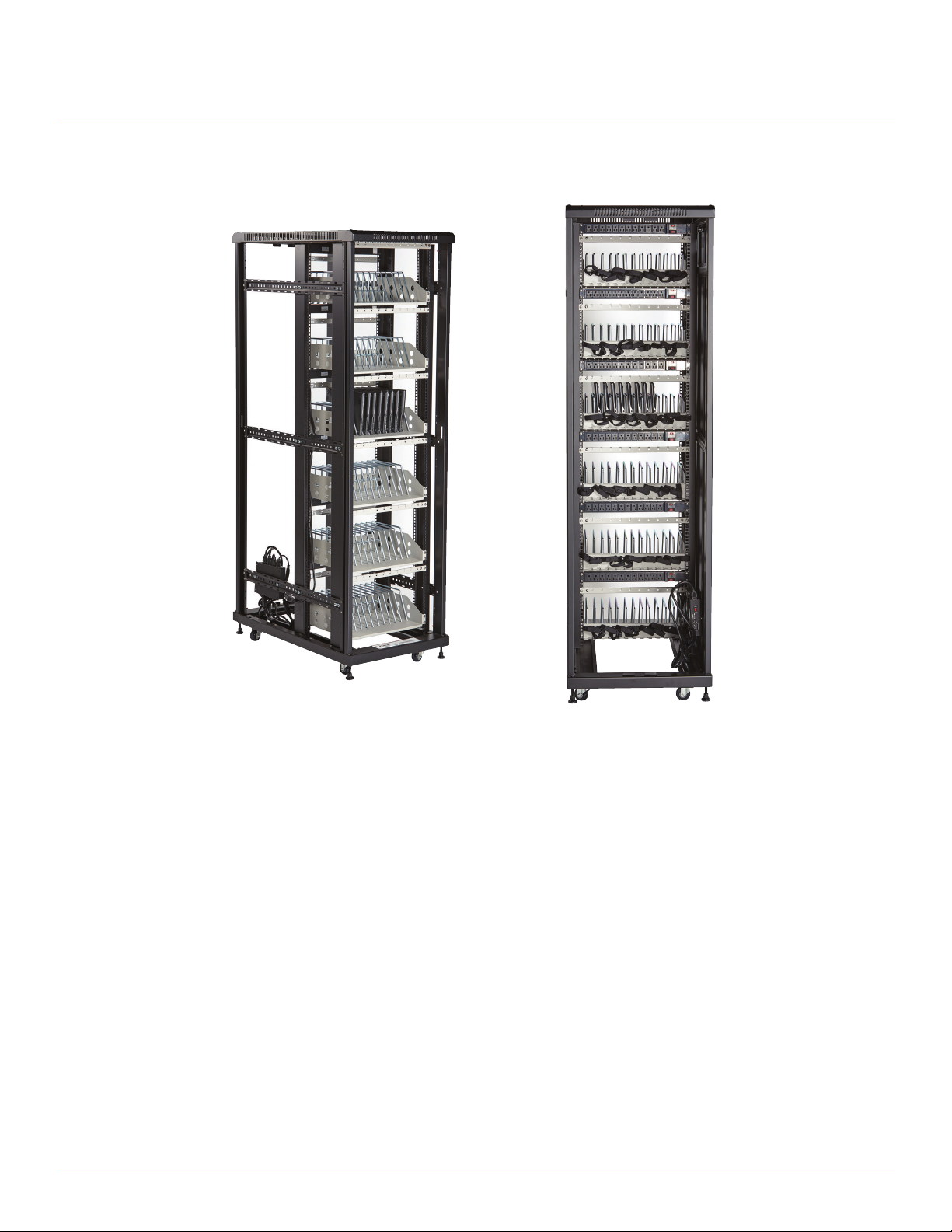
2.3.2 MSC-72-CCN and MSC-72-CNN
Chapter 2: Overview
Figure 2-4. Front and back of MSC-72-CCN or MSC-72-CNN cabinet, doors removed.
877-877-2269 | blackbox.com
Page 15
Page 16

Chapter 2: Overview
.
Figure 2-5. Front and back of MSC-72-CCN or MSC-72-CNN cabinet, doors open.
Figure 2-6. Front of MSC-72-CCN showing front cable management bars.
NOTE: The MSC-72-CNN does not have the optional front cable management bars installed. Otherwise, the MSC-72-CCN and MSC-
72-CNN are physically the same. Both models have rear cable management.
Page 16
877-877-2269 | blackbox.com
Page 17

2.4 Cabinet Configuration Examples for Tablet Storage and Charging
2.4.1 MSC-84-TCN and MSC-84-TNN
Chapter 2: Overview
Figure 2-7. Front and back of MSC-84-TCN or MSC-84-TNN cabinet, doors open.
Figure 2-8. Front of MSC-84-TCN showing front cable management bars.
NOTE: The MSC-84-TNN does not have the optional front cable management bars installed. Otherwise, the MSC-84-TCN and MSC-60-
TNN are physically the same. Both models have rear cable management.
877-877-2269 | blackbox.com
Page 17
Page 18

Chapter 2: Overview
2.4.2 MSC-96-TCN and MSC-96-TNN
Figure 2-9. Front and back of MSC-96-TCN or MSC-96-TNN cabinet, doors closed.
Page 18
877-877-2269 | blackbox.com
Page 19

.
Chapter 2: Overview
Figure 2-10. Front and back of MSC-96-TCN or MSC-96-TNN cabinet, doors open.
Figure 2-11. Front of MSC-96-TCN showing front cable management bars.
NOTE: The MSC-96-TNN does not have the optional front cable management bars installed. Otherwise, the MSC-96-TCN and MSC-96-
TNN are physically the same. Both models have rear cable management.
877-877-2269 | blackbox.com
Page 19
Page 20

Chapter 3: Configuration and Setup
3. Configuration and Setup
Remove and discard all packaging materials and then lock the lockable casters.
Open and inspect the Cabinet to verify all doors, locks, and casters are working properly.
Do not plug the Cabinet into a wall outlet until all configurations and setup are complete.
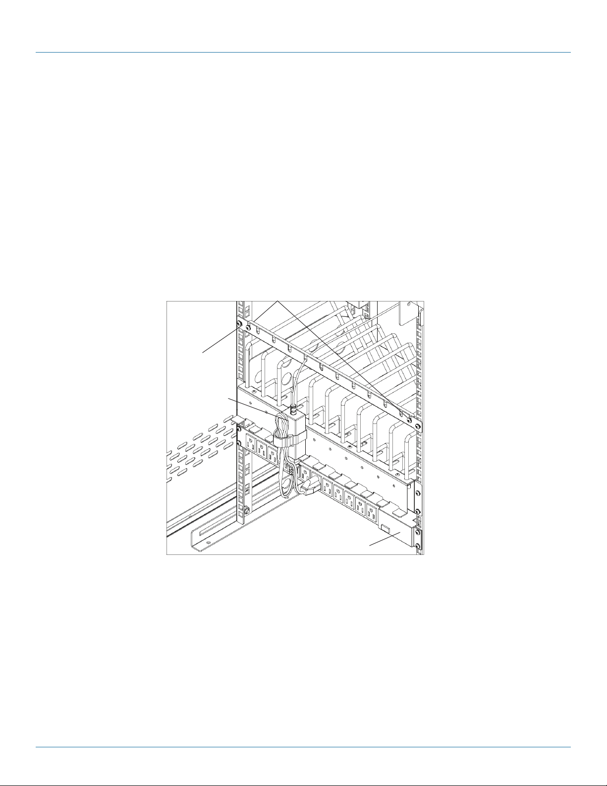
3.1 Routing the Cable (Applies to MSC-84, MSC-96, and MSC-192 Part Numbers, Cabinets with
Shelves sized for Tablets)
1. At the back of the Cabinet, loosen the two screws on the cable manager, pull up on the top section of the cable manager, and
place the device side of the charging cable into one of the slots. (See Figure 3-1.)
Loosen screws on cable manager
Cable
manager
Wrap excess cable
around cable wrap
and pull up
Charger
Figure 3-1. Cable routing inside the cabinet.
2. Replace the top section of the cable manager and tighten the screws.
Route cable to the
front of the cart
Power
Strip
3. Route the device side of the charging cable to the front of the cart and repeat step 1 for the front cable manager.
NOTE: The optional front cable management bars are included only with the MSC-84-TCN, MSC-96-TCN, and MSC-192-TCN.
4. Wrap any excess cable around the cable wrap on the back of the shelf.
5. Plug the charger power plug into the power strip located below the shelf.
Page 20
877-877-2269 | blackbox.com
Page 21

Chapter 3: Configuration and Setup
Loosen screws
on cable manager
and pull up
Cable
manager
Route cable to the
front of the cabinet
Figure 3-2. Routing the cable.
877-877-2269 | blackbox.com
Page 21
Page 22
Chapter 3: Configuration and Setup
3.2 Fastening the Power Bricks and Routing the Cable (Applies to MSC-60, MSC-72, MSC-144, and
MSC-168 Part Numbers, Cabinets with Shelves sized for Chromebook Computers and Laptops)
1. Attach the wrapped cord and power brick to the back of the shelf using the hook and loop strap. Keep some extra cable
unwrapped to plug into the power strip.
2. Loosen the two screws on the cable manager, pull up on the top section of the cable manager, and place the device side of
the charging cable into one of the slots.
3. Replace the top section of the cable manager and tighten the screws.
4. Route the device side of the charging cable to the front of the cart and repeat step 2 for the front cable manager (see Figure
3-3).
5. Plug the charger power plug into the power strip located below the shelf.
Cable
manager
Power block
and cord
Loosen screws on
cable manager and
pull up
Route cable to the
front of the cart
Power strip
Page 22
Figure 3-3. Fastening the power brick and routing the cable.
877-877-2269 | blackbox.com
Page 23

Chapter 4: Using Your Mass Charging Cabinet
4. Using Your Mass Charging Cabinet
NOTE: The Cabinets are designed to be stationary; casters are included only to initially position the Cabinet for setup in the
desired location.
4.1 Charging Your Computers
• After the devices have been loaded into the Cabinet, plug the power cord of the Cabinet into a suitable receptacle.
• For the models that have an Automated Power Controller included (MSC-60-CCN, MSC-60-CNN, MSC-72-CCN, and MSC-
72-CNN), locate the internal power switches on the Automated Power Controller and power strips of the Cabinet and push
the switches to the ON position.
4.2 Automated Power Controller Instructions
Before using your Automated Power Controller:
• For your safety, we recommend that a qualified electrician test the circuit you will plug the cart into. The circuit should be
checked for ground integrity and appropriate branch circuit protection.
• The cart’s ground prong must be present for safe operation. If the plug is damaged or if the ground prong has been removed,
it should be replaced by a qualified electrician.
• Using the cart, including plugging it in or unplugging it, plugging in or unplugging the laptop(s) or other electrical equipment,
or operating the control switch must be done with adult supervision.
The timer comes preset from the factory to alternate power between the power strips at 15-minute intervals.
All power strips cannot charge simultaneously.
By plugging the cart power cord into an approved outlet and flipping the red switches located on the automated power
controller and power strips, the cart will begin charging.
To end power, turn the red switch on the timer off and unplug the cart from the wall outlet.
877-877-2269 | blackbox.com
Page 23
Page 24

Chapter 5: Troubleshooting
5. Troubleshooting
5.1 Contacting Black Box
If you determine that your Mass Charging Cabinet is malfunctioning, do not attempt to alter or repair the unit. It contains no
user-serviceable parts. Contact Black Box Technical Support at 877-877-2269 or info@blackbox.com.
Before you do, make a record of the history of the problem. We will be able to provide more efficient and accurate assistance if
you have a complete description, including:
• the nature and duration of the problem.
• when the problem occurs.
• the components involved in the problem.
• any particular application that, when used, appears to create the problem or make it worse.
5.2 Shipping and Packaging
If you need to transport your Mass Charging Cabinet:
• Package it carefully. We recommend that you use the original container.
• If you are returning the unit, make sure you include everything you received with it. Before you ship for return or repair, contact
Black Box to get a Return Authorization (RA) number.
Page 24
877-877-2269 | blackbox.com
Page 25

NOTES
877-877-2269 | blackbox.com
Page 25
Page 26

NOTES
Page 26
877-877-2269 | blackbox.com
Page 27

NOTES
877-877-2269 | blackbox.com
Page 27
Page 28

Black Box Tech Support: FREE! Live. 24/7.
Tech support the
way it should be.
Great tech support is just 60 seconds away at 877-877-2269 or blackbox.com.
About Black Box
Black Box provides an extensive range of networking and infrastructure products. You’ll find everything from cabinets and racks
and power and surge protection products to media converters and Ethernet switches all supported by free, live 24/7 Tech support
available in 60 seconds or less.
© Copyright 2016. Black Box Corporation. All rights reserved. Black Box® and the Double Diamond logo are registered trademarks of BB Technologies, Inc.
Any third-party trademarks appearing in this manual are acknowledged to be the property of their respective owners.
msc-60-ccn_user_rev1
877-877-2269 | blackbox.com
 Loading...