

Page 1
rev. 3.0
MM-1
Microphone preamplifier & D.I.
Rev. 1.0
Page 2

REDEFINING WHAT A PREAMP CAN DO
(AGAIN)
The Black Box Analog Design MM-1 vacuum tube preamp is an entirely new
approach to capturing audio. It’s not based on any existing circuit but designed
from the ground up, using the best parts and ignoring all of the standard ideas
of how a preamp “should work”. We took the concept behind our original
microphone preamp, incorporated everything we discovered while building
the HG-2, made it even more exible, added features and even made it more
aordable! The result is an incredibly versatile piece of gear that not only
sounds amazing but shatters the idea of what a preamp can do!
Until now, a preamp simply amplied the signal; you essentially got one sound
and the ability turn it up or down. The MM-1 on the other hand allows you to
drastically shape the response curve of the unit without using an EQ, control
the harmonic content from pristine to full on saturation and even control the
dynamics without a compressor!
All of the shaping is done at the tubes and from the constantly variable
interaction between stages allowing you to dial in virtually unlimited tonal
possibilities. You can nd the sweet spot of any microphone and instrument
easily and naturally.
Congratulations on your new preamp!
Robert & Eric
Page 3
1
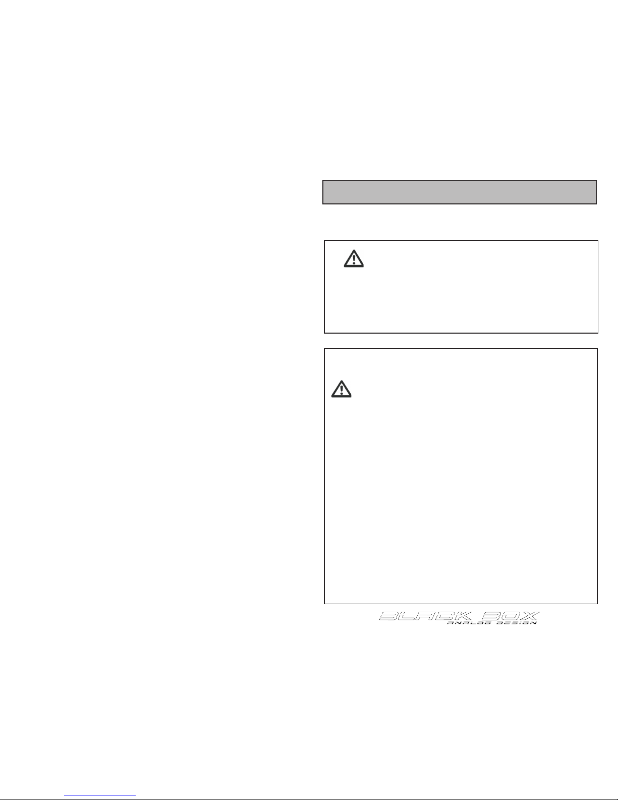
IMPORTANT SAFETY INFORMATION
READ ALL INSTRUCTIONS BEFORE USE
WARNING!
For your safety, the information in this manual
must be followed to minimize the risk of electric
shock. Failure to do so may result in property
damage, injury or loss of life.
IMPORTANT SAFETY INSTRUCTIONS
WARNING:
This device contains high voltage electricity
capable of delivering lethal shocks if used improperly.
Never, under any circumstances operate this unit without being
connected to a properly grounded circuit! If you are unsure,
consult an electrician to make sure your outlet is properly
grounded before plugging the unit in.
Do not attempt to service unit or open the case for any reason.
Internal capacitors are capable of delivering dangerous shocks
even after the unit has been unplugged.
• Never defeat ground using a ground lift or other device.
• Never expose unit to moisture or water
• Never connect a microphone to the unit if hands are wet/damp
• Do not plug in or operate unit if it is visibly damaged.
• Never replace fuse with a fuse of a dierent rating.
•
•
Page 4

3
INTRODUCTION
While no one likes to read manuals, the Black Box Analog Design™ MM-1 mic
pre is dierent than any other microphone preamplier both in how it’s
designed and how it functions so taking a few minutes to understand the
approach and controls will have you getting great tones MUCH faster!
READ ME!
WHAT IS SO DIFFERENT ABOUT IT?
(AND DOES IT REALLY CHANGE HOW I USE IT?)
Most microphone preampliers do one thing: increase the gain of a signal. While
that is great, we think a pre should do more. We think it should be able to help
you dial in tones and character, right there at the rst stage.
The MM-1 allows you to control how you capture a sound and get it right before
you ever hit tape or your converters! And yes, it does change how you use it. In
fact, once you get used to the controls, dialing in a tone and nding the sweet
spot feels more like playing an instrument than using a preamp.
With the MM-1, you have the ability to dramatically shape the frequency
response, harmonic content, saturation and even dynamic range. This control
means that you can do things never before possible with a preamp and that you
will hear your microphones and D.I. signals like you’ve never heard them before.
It also means that it’s possible to dial in tones that are not what you’re after so
understanding the controls and approach behind the unit is important. It might
seem dierent at rst but we promise that it’s actually really simple and a ton of
fun!
Page 5

4
5
WHAT DOES THIS BUTTON DO?
CONTROLS
ON
OFF
PAD
Low Cut
MM-1
IMP 48v
O
4080120
160
RESPONSE AIR
INST
1
2
3 556
7
8
9
10
11
48 volt Phantom power fed by an isolated, regulated, linear supply
Phase switch
5 position, low end roll-o selector
Pentode gain control
10db input pad
“Response” selection
“Air” engages the air circuit from the HG-2 (10k harmonic shelf)
Triode gain control
3 way power switch with O/Standby/On positions: Standby mode sends
power to the tube heaters and LEDs
1
Input impedance selector: Impedance is switched by tapping into the
transformer at dierent points in the winding.
2
3
4
5
6
7
8
9
10
11
Instrument input
Passive output attenuation
14 15
16
14
Master on/o switch: In the “o ” position, no power will reach the face plate
and the front panel power switch will be inoperable. Be aware that in the
“on” position, power is present inside the box even when the power switch
on the front panel is in the “o” position.
15
2AG power fuse: Replace only with the same rating fuse (2amp)
16
Microphone input
17
Balanced, line level output
Voltage selection switch
18
110
4
4
12
12
17 18
Page 6

6
7
CONTROLS
A CLOSER LOOK
While nding the sweet spot and getting the right tone with the MM-1 pre
is more about feel than anything, it is still helpful to know how each part of
the circuit behaves and reacts. This section goes into more detail about what
each control/stage does.
Pentode Stage (‘response’ disengaged)
Pentode Stage (‘response’ engaged)
The Pentode stage is the rst amplication stage and gives you extreme
control over the frequency response of the mic pre as well as gain and beautiful
harmonics. In the graph below you can see that when “response” is disengaged,
the Pentode has a frequency response that “tilts” around a xed top end
depending on the gain setting. As you increase the gain, you also increase the
low end.
When the alternate response mode is engaged (by pushing the ‘Response’
button), the top end of the Pentode stage is no longer xed. The Pentode stage
will still tilt but the top end has a gentle roll o to allow for an entirely new set of
frequency responses.
The Pentode can also be pushed into the Triode much the way you can drive
one stage of a guitar amplier into the next. The result here is of course much
more subtle but it can have a very pleasing eect.
CONTROLS
Triode Stage
Air
Output
The Triode stage of the circuit is located after the Pentode stage and can be
thought of as “drive”. Rather than the frequency control of the Pentode stage,
the Triode stage is linear so it can be used to amplify the response curve of the
Pentode stage as much as desired.
The triode stage is set up to allow for clean amplication of the signal as well as
the ability to drive the signal into saturation. The Triode stage is set up to output
a voltage swing of no more than 30 volts no matter the input so as you drive into
the tube (both with the Pentode and Triode knobs), you begin to get harmonics,
followed by saturation and eventually hard limiting without the artifacts
associated with the attack and release of a compressor.
The “Air” circuit is the same beloved circuit from the HG-2. Engaging the circuit
adds a 10k shelf boost, made up mostly of harmonics for a lift that opens up your
material.
The output knob is a passive attenuation after the Triode stage and can be used
to set the overall output of the MM-1.
Input impedance
Unlike most impedance switches on preamps today, we use real impedance
switching by tapping into the custom made transformer at dierent points in the
windings.
While the low impedance setting (button in) would usually be used for ribbon
microphones, it sounds amazing on condensers and dynamics alike. In this
mode you get a very mid-forward sound and an increase in gain and punch. The
best way to describe the dierence on a vocal track for example is the dierence
between an uncompressed vocal and a gently compressed one. It can do
wonders for lead vocals and they often sit in the mix with authority right where
you want them. This setting also allows you to back a singer o the microphone
while still capturing all the detail without any of the excess sibilance, mouth noise
and proximity issues.
The default setting (button out) is a more standard setting and sounds more
“relaxed”. It works well for lead vocals as well as backing vocals or stacks that sit
perfectly in the mix and gives a very natural response on any source.
Low Roll-o
This simple roll-o circuit has been designed to give you a gentle roll o that
allows you to lter out unwanted low end without adding large resonance peaks
at the cuto frequency.
Instrument D.I.
The instrument D.I. of the MM-1 follows the same signal path as the microphone
input with the exception of the input transformer. The controls and gain stages
allows for the same unique control over the signal. The D.I. is automatically
activated when an instrument cable is inserted into it.
Page 7

9
- Set the Triode and Output to 12 o’clock
- Start with the Pentode
- Switch the response and Impedance
- Low frequency roll o
- Triode
Start with the Pentode at zero (no sound will pass) and begin to turn the knob
clockwise. As you do, you will hear the response tilt, adding more and more low
end as you increase the gain while the top end stays xed.
While adjusting the Pentode knob, switch the ‘response’ setting and you will
hear the top end change as it switches from being xed (regardless of Pentode
position) to rolled o, allowing for new frequency response curves.
Switching the input impedance will give you yet another set of response curves
and possible combinations.
Along with the Pentode knob, input impedance and ‘response’ options, the low
end roll o selector will help you shape the frequency response. Rather than a
steep HPF, the roll o is an extremely gentle slope that extends all the way to
the midrange with a 1db drop at 1k in the fully clockwise position. This gentle
approach not only sounds more musical and natural but allows you to achieve a
wide range of frequency response curves in conjunction with the other controls.
Once you’ve achieved the frequency response you are after, adjust the Triode
stage to drive that signal. Start by lowering the Triode and compensating
by turning the output all the way up. This will result in extremely clean, high
headroom amplication. As you increase the Triode gain, compensate as needed
at the output and you will hear the Triode tube begin to add beautiful harmonics,
saturation and eventually compression and limiting. By “squeezing” the signal
between these two stages, you can actually control the dynamics of your material
in an incredibly natural way and still get exactly the output you need for the next
stage.
IN USE
LET’S SHAPE TONE!
With an understanding of how each stage operates, lets look at how they can
be used together to control what you capture.
Page 8

10
11
EXAMPLES IN USE EXAMPLES IN USE
ON
OFF
PAD
Low Cut
MM-1
IMP 48v
O
4080120
160
RESPONSE AIR
INST
8
-80
-60
-40
-20
16 31 62 125 250 500 1000 2000 4000 8000 16000
ON
OFF
PAD
Low Cut
MM-1
IMP 48v
O
4080120
160
RESPONSE AIR
INST
8
-80
-60
-40
-20
16 31 62 125 250 500 1000 2000 4000 8000 16000
‘Response’ out
‘Response’ in (volume oset for graph)
‘Response’ & Impedance in (volume oset for graph)
ON
OFF
PAD
Low Cut
MM-1
IMP 48v
O
4080120
160
RESPONSE AIR
INST
8
-80
-60
-40
-20
16 31 62 125 250 500 1000 2000 4000 8000 16000
ON
OFF
PAD
Low Cut
MM-1
IMP 48v
O
4080120
160
RESPONSE AIR
INST
Impedance out
Impedance in
8
-80
-60
-40
-20
16 31 62 125 250 500 1000 2000 4000 8000 16000
High tilt
Mid push
Mid scoop
Flat &
Low bump
Page 9

12
ON
OFF
PAD
Low Cut
MM-1
IMP 48v
O
40
80
120
160
RESPONSE AIR
INST
SESSION: ____________________________________________ DATE: _______________
NOTES:
TRACK: ______________________________________________
MAINTENANCE / CALIBRATION
Replacing the tubes
Under normal conditions, the tubes in the MM-1 should have a long, hassle
free life but eventually all tubes need to be replaced. With this in mind, the
MM-1 has been designed to use readily available and easily replaceable
tubes that need no biasing or calibration when replaced.
There are two tubes in the MM-1 and it is
important to replace each with the correct tube.
Pentode Tube (located on the main PCB)
Triode Tube (visible through the front panel cutout)
The MM-1 ships with an Electro Harmonix 6922 tube in this position.
These tubes sound fantastic in this circuit but there are a number of high end
variations available as well.
The MM-1 ships with an Electro Harmonix EF86 tube in this position.
These tubes also have several variations available as well.
Air Calibration
The only internal adjustment/calibration in the MM-1 is the air adjustment. Like
the original air circuit in the HG-2, the gain of the air circuit can be adjusted based
on the user’s preference. The adjustment is a single turn trim resistor located at
the front right corner of the main PCB (looking from the front) and is labeled “air”.
As with the HG-2, as you increase the gain, the frequency also shifts up slightly.
Page 10

 Loading...