

Page 1
Manual of VDSL2 Solution
http://www.black-box.eu
_____________________________________________________________________________
Manual
MEG201AE
VDSL2 Ethernet Extender Kit
VDSL2 Point to Point Solution
Consisting of 1xTransmitter and 1xReceiver
MEG201RAE
VDSL2 Receiver
Part of VDSL2 Point to Multipoint Solution
used with VDSL2 Switch MEG821AE
MEG201TAE
VDSL2 Transmitter
Page 2

Manual of VDSL2 Solution
http://www.black-box.eu
_____________________________________________________________________________
OVERVIEW
MEG201AE works as a transparent point to point Bridge for Ethernet and/or Telephony
connections using a Transmitter and a Receiver. When used with the VDSL2 switch
MEG821AE it is a Multipoint to Point solution. The MEG201AE uses new VDSL2
technology operating at different frequency bands with the feature to adapt its
performance to the characteristics of the copper medium used. The following cable
lengths and bandwidths are possible according to the band profile setup:
30a (Default band profile) 0-350m at 100Mbps down- and upstream
350-450m at 70-85/40Mbps downstream/upstream
450-600m at 40-60/10Mbps downstream/upstream
600-900m at 20-40/1-5Mbps downstream/upstream
Using Band profile 30a for distances
beyond 900m is not recommended
8d (Alternative band profile) 0-800m at 60-80/15 Mbps downstream/upstream
800-1200m at 30-50/5-10 Mbps downstream/upstream
1200-1500m at 30/2-5 Mbps downstream/upstream
Using Band profile 8a for distances
beyond 1500m is not recommended
Downstream: Traffic from Transmitter to Receiver
Upstream: Traffic from Receiver to Transmitter
For distances higher than those mentioned above, the MEG201AE is not the
recommended product. Other Black Box xDSL products should then be your
choice. Check MDS93x, MDS95x, MDE5xxx or MEG101 series products to get
distances of many many kilometers
These distances may and will vary depending on the quality of your wires. Keep in mind
that every intermediate connection of the cable will possibly increase losses and result in
less reach and/or bandwidth. Avoid cables that are not truly isolated, that may get wet or
are old and corroded. Running high power current nearby is also not recommended due
to the possibility of induced interference.
Avoid using telephony RJ11 ribbon cables. These cables are built with using very
low diameter stranded cables. Using them will mean that bandwidth is lower and
reach is shorter!
Page 3

Manual of VDSL2 Solution
http://www.black-box.eu
_____________________________________________________________________________
The front-panel provides LED indication of system and interface status. The in-built
POTS splitter allows a standard POTS phone to be connected at the Receiver. Full or
half duplex mode LAN operation is automatically sensed and configured. The
MEG201AE features an integrated 4 Port 10/100 Switch. Because of the switch please
consider that some non standard Ethernet Frames will not pass MEG201AE.
MEG201AE is configured by Web management. The serial port is intended to be used
by support staff with technical skills only. The standard IP addresses of the MEG201AE
set up are:
Transmitter MEG201TAE 192.168.16.249
Receiver MEG201RAE 192.168.16.250
Use the Webbrowser of your choice (older versions of Netscape or IE may not be able to
show you all options) to address MEG201AE. The default password is admin
Page 4

Manual of VDSL2 Solution
http://www.black-box.eu
_____________________________________________________________________________
The Modem
From Left To Right
1 Just a hole where in previous versions a RESET button was
2 4x10/100 LAN Ports
3 VDSL Link Port, middle Pins active (RJ11)
4 Phone POTS ab Port, middle Pins active (RJ11)
Transmitter side intended to use with a PBX (FXO)
Receiver side intended to use with a telephone or telefax (FXS)
5 Serial RS232 Port for use by authorized personnel only
6 Power Input (12VDC, max.1A)
From Left To Right
PWR Power LED
E1-E4 Link LED for the Ethernet Switch Ports
Blinking while ongoing Activity
LINK Link LED for the VDSL Port
Blinking while other side found and connection is being established
Steady On while VDSL Link valid
Note: Pictures in the manual mainly show the modem in white. Thanks to the features of digital photography.
Of course MEG201AE is black and is only available in black.
Page 5
Manual of VDSL2 Solution
http://www.black-box.eu
_____________________________________________________________________________
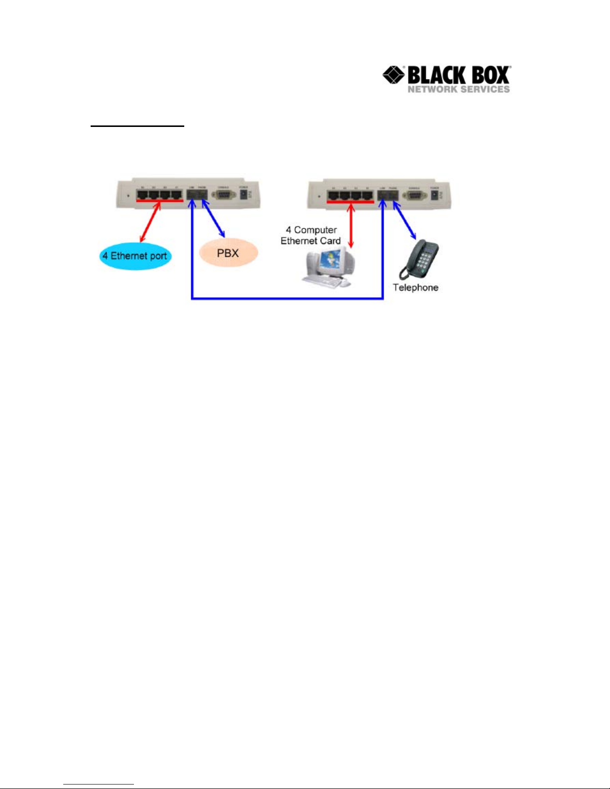
INSTALLATION
For most applications you just need to connect the Transmitter and Receiver and power
them up (Picture shows Transmitter on the Left, Receiver on the Right)
Since the Receiver and Transmitter have their own IP addresses please check that the
addresses 192.168.16.249 and 192.168.16.250 are not in use by any other of your
network equipment. Initially, it may be useful for you to just connect Transmitter and
Receiver to the VDSL Line without connecting any other network equipment.
When using the VDSL2 switch (MEG821AE) please do not forget that all Receivers have
the same default IP address. It is recommended to change the IP address of each
receiver on its own before connecting to the switch.
For wire lengths within the distance limits previously mentioned (<900m), the system will
automatically establish the Link and set itself up. The MEG201AE is built using a
switching chipset and so some special Ethernet Frames will not pass across the VDSL
Link. Standard TCP und UDP traffic will pass to the other side transparently. The
MEG201AE is optimised for TCP traffic. If you use UDP traffic for Video Transmission
with high Frame sizes you will experience non optimal results.
After the Link between the Transmitter and Receiver has been established successfully
the WAN/LINK LED will be in a steady on state. At this point you should set up
appropriate IP addresses for the Transmitter and Receiver. You do this by either using a
PC within the subnet of the default IP addresses (192.168.16.x) or by setting a
temporary IP address by RS232 connection. See the next chapters for more information.
Page 6

Manual of VDSL2 Solution
http://www.black-box.eu
_____________________________________________________________________________
CONFIGURING BY WEB
The MEG201AE can be configured by using a Web browser. The modems have default
IP addresses and to use the Web Configuration method you need a PC within the same
subnet as the default IP addresses of MEG201AE.
MEG201AE Transmitter 192.168.16.249
MEG201AE Receiver 192.168.16.250
You can for example set your PC up with IP address 192.168.16.1. Please consult the
manual of your operating system on how to do this. If you can not change the IP address
of your PC then choose the alternative method to configure the IP address of
MEG201AE by RS232 serial (see below).
By entering the IP address as the URL into your browser you can get access. A window
will appear asking you for login. The default password is admin.
(Transmitter on Left, Receiver on Right)
The Screen you will see looks very similar for both the Transmitter and Receiver. Click
on Advanced Setup to configure the modem. The next screen will show you:
Page 7

Manual of VDSL2 Solution
http://www.black-box.eu
_____________________________________________________________________________
As you can see the Receiver offers you more options to configure. This is because you
can use the Receiver as an ADSL2+ Modem to be used with your incoming Internet
Service Provider Line as well as a point to point solution. Since the purpose of this
manual is to describe setup for your VDSL2 link please leave the options for
WAN/NAT/Firewall/Route and uPnP unchanged!
SYSTEM
Administator Settings (Transmitter and Receiver)
Allows you to change the default password
Firmware Upgrade (Transmitter and Receiver)
Allows you to upgrade the firmware
Device Mode (Receiver only)
Allows you to change the Receiver from VDSL2 Extender Set to ADSL2+ Router. Leave
setting to Switch Mode for normal operation
(Switch Mode in Factory Default)
System Status
Information about the Device
Reboot
Lets you reboot the Device while leaving the settings unchanged
Reset System
Lets you reboot the Device while setting everything back to factory default
LAN
LAN Settings
Lets you configure IP Address and enable or disable the DHCP Server
(Disabled in Factory Default)
DHCP Client List
Lets you view the IP Addresses given to network devices by the DHCP Server
LAN Switch Port Setting
Lets you configure which Speed and Duplex Mode ALL 4 SWITCH PORTS do.
(Auto 10/100 Full/Half in Factory Default)
LAN Port Status
Lets you view the status of the four Switch Ports.
Page 8

Manual of VDSL2 Solution
http://www.black-box.eu
_____________________________________________________________________________
VDSL2
Channel Config
Lets you control the bandwidth passing across the Link.
(Factory Default is 64 kbps Minimum and 102400 kbps Maximum)
Also gives you the chance to set up Interleave. Higher Interleave values may give you a
more consistent latency.
(Factory Default is 1ms)
Line Config
Lets you configure the target SNR value for your Link that is acceptable. By lowering
that value you may get a link at a higher reach, but it will not be stable.
(Factory Default is 6 db)
Profile Config
Lets you configure the profile being used for your Link.
You can choose Profile, Band Plan, Filter and Tone Mode for the Transmitter.
You can choose Filter and Tone Mode for the Receiver.
Filter and Tone Mode of Transmitter and Receiver need to match.
(Factory Default for Filter is Off, for Tone Mode is V43)
The choosen Profile and Band Plan of the Transmitter are automatically
detected by the Receiver
The Profile and Band Plan tell the Modems which frequencies are being used and how
data is processed and transferred. The Filter and Tone Mode tells the modem
specialities about the line.
Optimal Setups:
Profile 30a, Annex C_8K, Filter Off and Tone Mode V43 for High Bandwidth
Profile 8d, Annex A M1_EU32, Filter Off and Tone Mode B43 for Long Distance
Bands Config
Let you configure special frequencies to be used.
Do not make any changes unless specifically advised by Black Box!
LoopBack
Enable LoopBack Functions for Testing
Users are not intended to use this function !
Activate Deactivate
Activate or Deactivate the Link
The Link needs to be activated on both sides to operate
LineStatus
For every Frequency section you can view the SNR values.
They should be positive and the higher, the better.
ChannelStatus
The Link performance
VersionInfo
Detailed Information about the software and hardware of MEG201AE
SNRGraph
Graphics showing you SNR values
BitsGraph
Graphics showing you where how much data is transferred.
Page 9

Manual of VDSL2 Solution
http://www.black-box.eu
_____________________________________________________________________________
CONFIGURING BY RS232
MEG201AE features a Serial RS232 Port. Use a straight through (1:1) cable to configure
the MEG201AE using Hyperterminal or any VT100 application of your choice.
You need to setup a bitrate of 115200bps with 8N1 without any handshaking.
If the MEG201AE has been powered up already you will see a prompt by hitting the
ENTER key:
/ #
If you have not powered up MEG201AE, please do so and wait until the boot process is
finished. The boot process finishes with the following (for the Transmitter, the Receiver
looks very similar):
MEG201AE VDSL Transmitter
Image V 2.0.12 (CO)
FW: v9.7.3.11.0.2
DSL-API: v2.0.12
DFE-Drv: v0.1.4.8
WEB-Interface: vD.2x
--------------------------------------------------------------
-------------------------------------------------------------Addr: 1200007c, value: bfffffff
BusyBox v1.00 (2006.05.29-14:43+0000) Built-in shell (ash)
Enter 'help' for a list of built-in commands.
/ #
As you may identify from the commands above MEG201AE is a Linux based device.
Many of the common Linux commands can be used here. However, please consider that
you purchased a VDSL2 modem device, not a PC. And always keep in mind that Black
Box gives you support for configuring a standard VDSL2 modem. If you try to use the
MEG201AE as a Linux hardware platform and modify its internal software structure
there is no support or warranty on the unit.
Page 10

Manual of VDSL2 Solution
http://www.black-box.eu
_____________________________________________________________________________
You can use the Serial Interface to configure an IP address by this command:
ifconfig adm0 <ipadress> netmask <subnetmask>
(Example: ifconfig adm0 192.168.16.240 netmask 255.255.255.0)
This configuration is activated immediately but is only temporary because not stored in
flash memory. We recommend you continue configuring by Web method.
Other commands very useful:
rawaccess –e (Factory Default)
reboot (RESET)
ping (check connectivity to an IP address)
The Serial Bootmenu
Sometimes it may be necessary to use the Serial Bootmenu. Please check with Black
Box Tech Support before you attempting to do so.
While powering up the MEG201AE you can stop the boot process while this message is
displayed. Press SPACE three times to enter the boot menu then:
Press <space> key tree times to enter boot menu..
2
Loader Menu
==================================
[1] Xmodem Download
[2] TFTP Client Download
[3] Print Boot Params
[4] Set Boot Params
[5] Update bootloader
[6] Exit
Please enter your number:
Option 1 enables you to upgrade the firmware by RS232 with Xmodem. This is a very
slow but very secure upgrade method.
Option 2 enables you to upgrade the firmware by TFTP.
Option 3 will give you information about the device
Option 4 enables you to change CO/CPE status
Option 5 enables you to upgrade the bootloader
It is not recommended to use any of these options without consulting Black Box or
unless specifically instructed by Black Box tech support to do so.
Page 11

Manual of VDSL2 Solution
http://www.black-box.eu
_____________________________________________________________________________
FIRMWARE UPGRADE
New Firmware Files may be available on ftp://ftp.all-about-kvm.com
You can download a ZIP File with two binary files.
One file mentions “CO” in the filename and
is intended to be used with the Transmitter only.
One file mentions “CPE” in the filename and
Is intended to be used with the Receiver only.
Avoid using any firmware file that sounds or looks like it is suitable for MEG201AE. Use
only firmware files you retrieved yourself from our website or have been mailed to you by
Black Box personnel.
There are three ways to upgrade your MEG201AE:
a.) By Serial and XModem
This is the recommended option. Get into the Serial Bootmenu of MEG201AE. In the
Bootmenu select Option 1 and upload the appropriate file (CO for Transmitter, CPE for
Receiver) with XModem Protocol.
b.) By TFTP
This is the fastest method, but you need a TFTP Server and some skills. Get into the
Serial Bootmenu of MEG201AE. Select Option 2
At first choose Option S to set TFTP Parameters. You will be asked for the TFTP Server
IP (probably IP Address of your PC running the TFTP Server), the Remote File Name
(which is the filename of the appropriate firmware file (CO for Transmitter, CPE for
Receiver)) and a temporary IP Address for the VDSL2 device to download the file
(Needs to be an IP Address in the same subnet of your network). After having entered
these values be sure to have the TFTP Server set up and running with the firmware file
in the main directory. Then start the download with Option D.
c.) By Web
Firmware Upgrade is also possible by Web. Log on to MEG201AE, choose SYSTEM
and then Firmware Upgrade. Upload CO for Transmitter and CPE for Receiver. Click on
Apply and wait.
No matter which method you choose, after the upgrade you need to reset to factory
default. Do not interrupt MEG201AE while upgrading. Repowering MEG201AE after
upgrade and factory default is needed additionally in order to reset the VDSL2 chip.
Page 12

Manual of VDSL2 Solution
http://www.black-box.eu
_____________________________________________________________________________
HOW TO CHANGE IP ADDRESS
Option A: Using Default IP address
1 Set your PC address to IP address 192.168.16.1
2 Start your Browser
3 Go to URL 192.168.16.249
4 Login with password
5 Click on Advanced Setup (top right)
6 Click on LAN (on the left)
7 Click on LAN settings (showing up below LAN)
8 Enter the IP address of your choice
9 Click on Apply
10 Repeat from Step 3 with URL 192.168.16.250
Option B: Temporarily Changing IP address
1 Attach a straight through 1:1 serial cable
2 Start Hyperterminal
3 Open a serial session to your COM Port with 115200 Bps 8N1 No Handshake
4 Press Enter
5 Prompt shows up
6 Enter command ifconfig adm0 <ipadress> netmask <netmask>
7 Start your browser
8 Go to URL <ipadress> (Choose the one you entered in Step 6)
9 Login with password
10 Click on Advanced Setup (top right)
11 Click on LAN (on the left)
12 Click on LAN settings (showing up below LAN)
13
Check the IP address
14
Click on Apply
15
Repeat from Step 1 with the other modem
Page 13

Manual of VDSL2 Solution
http://www.black-box.eu
_____________________________________________________________________________
Troubleshooting
Symptom: Power indicator does not light up (green) after being powered on.
Cause: Defective External power supply
Solution: Check the power plug by plugging in another suitable power supply.
Check the power cord with another device. If this fails to resolve the problem,
have the power supply replaced.(KVT127E-PS)
Symptom: Link indicator E1,E2,E3 or E4 does not light up (green) after making a connection.
Cause: Network interface, network cable, or switch port is defective.
Solution: Power off and re-power the VDSL Modem.
Verify that the switch and attached devices are powered on.
Be sure the cable is plugged into both the switch and corresponding
device. Check LED activity on your switch or corresponding Ethernet
Device. Verify that the proper cable type is used and its length does
not exceed specified limits (100 Meter). Check the Modem on the
attached device and cable connections for possible defects.
Replace the defective Modem or cable if necessary.
Symptom
: VDSL Link cannot be established
Cause
: cable length is over specification or no connection
Solution
: Please make sure phone wire must be connected between
Transmitter and Reciver when both are power on. Use middle Pins of
the RJ11 line port. Avoid using RJ11 telephony ribbon cables.
Try to setup Bandprofile 8a and check that Filter and Tone Mode are
Setup identically.
What does not or may not work with MEG201 series products?
Jumbo Frames, max. Frame Size is 1536 bytes
Transmission of non-standard protocols
Routing just by using the VDSL Extender Set
PoE to provide power or to get power from modems
(If you require this, call Black Box for information on MPG101AE-R2)
Using with Black Box DTX5000 System
ISDN BRI/PRI/S0 or E1/G703 transmission by POTS port
Digital 2 wire phone connections like Up0E
Page 14

Manual of VDSL2 Solution
http://www.black-box.eu
_____________________________________________________________________________
What can I do if my line is too long?
Often there are different routes to get to the “other side”. Try to find out if there is
a shorter or better quality alternative. If not, Black Box has other xDSL devices that will
provide long distance connection.
Please check MDS932AE-10BT-R2, MDS952AE-10BT and/or MDS5110AE,
MDE5210E/MDE5211E to be an alternative for your application by calling your Black
Box office. Check www.blackbox.eu for local mail addresses, phone and fax-numbers.
Tech Support
It is our main philosophy to provide high quality service and support on Black Box
products and equipment. If you have any questions please feel free to contact Black Box
Free Tech Support. Check www.blackbox.eu for phone numbers of your local office.
Page 15

Manual of VDSL2 Solution
http://www.black-box.eu
_____________________________________________________________________________
Product Features & Specification
=> Compliant with IEEE802.3 10BASE-T standard.
=> Compliant with IEEE802.3u 100BASE-TX standard.
=> Compliant with ETSI, ITU, ANSI standards
=> Max bandwidth is 100Mbps up to 350m
Max distance is 900m with Profile 30a and 1500m with 8a
=> Supports 1 * RJ-11 connector for Ethernet over VDSL.
=> Supports 1 * RJ-11 connector for telephone/PBX connection.
=> Supports 4 * RJ-45 port for 10/100Mbps Ethernet with Auto MDI/MDIX.
=> Supports long packet size up to 1536 bytes
=> Voice and Data work on the same 2 wire telephone line.
=> Supports flow control IEEE802.3x for Full Duplex & Back Pressure
for Half Duplex.
=> Supports Surge protection.
=> Provides LED indication Power, Link/Active Status for Ethernet port
and Link for VDSL port.
=> External switching power adapter Input: AC 85-240 volts/50-60Hz;
Output: DC 5V/1A or above.
=> Power Consumption: Transmitter&Receiver 7.5W
=> Operating Temperature: 0°C ~ 50°C (41F ~ 122F)
=> Storage Temperature: -20°C ~ 65°C (-4F ~ 149F)
=> Humidity: 10 to 90% (non-condensing)
=> Dimensions: 184 x 146 x 40 mm (7.2" x 5.74" x 1.57").
Available Accessories:
MEG201AE VDSL2 Extender Set (1xTransmitter, 1xReceiver)
MEG201TAE VDSL2 Transmitter
MEG201RAE VDSL2 Receiver
MEG821AE VDSL2 8 Port Switch
MDS9XX-DIN DIN Rail Mounting Set
KVT127E-PS Spare Power Supply for International Use
Page 16

Manual of VDSL2 Solution
http://www.black-box.eu
_____________________________________________________________________________
 Loading...