

Page 1
USER MANUAL
ME890A E-R2
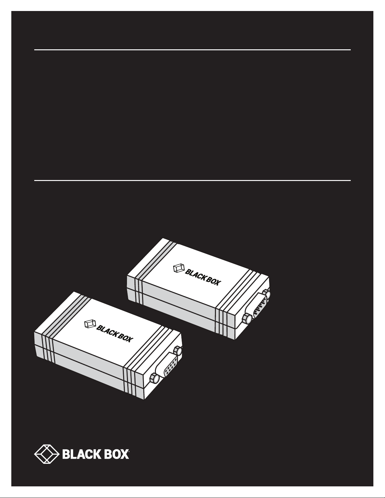
CAT X DB9
LINE DRIVER
24/7 TECHNICAL SUPPORT AT 1.877.877.2269 OR VISIT BLACKBOX.CO M
RJ45
5 VDC
CATX DB9 LINE DRIVER
RJ45
5 VDC
CATX DB9 LINE DRIVER
DB9-RS232
DB9-RS232
Page 2

NEED HELP?
LEAV E TH E TEC H TO US
LIVE 24/7
TABLE OF CONTENTS
TECHNICAL
SUPPORT
1. 8 7 7. 8 7 7. 2 2 6 9
1. SPECIFICATIONS ........................................................................................................................................................................... 3
2. OVERVIE W ...................................................................................................................................................................................... 4
2.1 Introduction ...............................................................................................................................................................................................4
2.2 Features .................................................................................................................................................................................................... 4
2.3 What’s Included ........................................................................................................................................................................................4
2.4 Hardware Description ..............................................................................................................................................................................5
2.4.1 Local Unit .............................................................................................................................................................................................................5
2.4.2 Remote Unit .........................................................................................................................................................................................................6
2.5 Application Diagram ................................................................................................................................................................................6
3. I NSTALLATION .............................................................................................................................................................................. 7
3.1 Installation Steps ......................................................................................................................................................................................7
3.2 DB9 Pinout ................................................................................................................................................................................................7
3.3 RJ-45 Pinout ............................................................................................................................................................................................. 8
4. TROUBLESHOOTING ..................................................................................................................................................................... 9
4.1 Problems/Solutions .................................................................................................................................................................................9
4.2 Contacting Black Box ...............................................................................................................................................................................9
4.3 Shipping and Packaging .......................................................................................................................................................................... 9
APPENDIX. REGULATORY INFORMATION .................................................................................................................................... 10
A.1 FCC Statement ....................................................................................................................................................................................... 10
A.2 NOM Statement ..................................................................................................................................................................................... 11
TRADEMARKS USED IN THIS MANUAL ........................................................................................................................................ 12
2
1. 8 7 7. 8 7 7. 22 6 9 BL ACK BOX .COM
Page 3

NEED HELP?
LEAV E TH E TEC H TO US
LIVE 24/7
CHAPTER 1: SPECIFICATIONS
TECHNICAL
SUPPORT
1. 8 7 7. 8 7 7. 2 2 6 9
TABLE 1-1. SPECIFICATIONS
SPECIFICATION DESCRIPTION
Power
Input: 100–240 VAC, 47–63 Hz;
Power Supply
Interface
Interface
Flow Control RTS/CTS
Mechanical
Dimensions 0.8"H x 1.7"W x 3.2"D (2.1 x 4.3 x 8.1 cm)
Weight 2.0 lb. (0.9 kg), including local unit, remote unit, and (2) power supplies
Data Transmission
Data Format Asynchronous, Full-Duplex
Maximum Distances/Data Rates
Isolation 1000 VDC isolation between RS-232 interface and RS-485 interface
Cables and Connectors
Interconnect Cable Four-pair twisted-pair cable, low-capacitance CAT5 or CAT6 recommended for best performance
Connectors
Environmental
Temperature
Humidity (non-condensing)
Output: 5 VDC with universal plug kit;
PSE approved
DB9: EIA RS-232-F, ITU v.28;
RJ-45: RS-485
4000 ft. (1250 m) for data rates < or = 100 kbps;
2000 ft. (625 m) for data rates < or = 200 kbps;
1500 ft. (468 m) for data rates < or = 250 kbps
NOTE: The combined RS-232 cable and device load should be < or = 1000 pf and > or = 3 kohm in order to
operate at 250 kbps
(1) DB9 female (local),
(1) DB9 male (remote),
(1) RJ - 45,
(1) DC power jack
Operating: 32 to 140° F (0 to 60° C);
Storage: -14 to +158° F (-10 to +70° C)
Operating: 20 to 80%;
Storage: 10 to 90%
1. 8 7 7. 8 7 7. 22 6 9 BL ACK BOX .COM
3
Page 4

NEED HELP?
LEAV E TH E TEC H TO US
LIVE 24/7
CHAPTER 2: OVERVIEW
TECHNICAL
SUPPORT
1. 8 7 7. 8 7 7. 2 2 6 9
2.1 INTRODUCTION
The CATx DB9 Line Drivers enable you to position your receiving device up to 4000 feet (1250 m) from the sending device. The local
unit has a DB9 female connector and is configured as a DCE device. The remote unit has a DB9 male connector and is configured
as a DTE device. This allows the local/remote pair to function as a long extension cable between two RS-232 devices. There are
no user-configurable settings.
The local and remote units are connected with a CAT5 or CAT6 twisted-pair cable. The local and remote units swap the RJ-45 pins
so a straight-pinned cable is required. The units are isolated to provide protection from differences in ground potential between
the units. The units pass TXD, RXD, RTS, and CTS signals to allow the application to use hardware handshake signals if required.
The local unit provides an active high output on DSR and DCD, while the remote unit provides an active high output on DTR.
2.2 FEATURES
Signals include RD, TD, RTS, CTS, GND, plus DTR (or DSR) asserted
Local and remote units can be up to 4000 feet (1250 m) apart
No configuration needed
Fixed DCE local and DTE remote
Operates point-to-point in full-duplex mode
Provides 1000-VDC isolation between RS-232 interface and RS-485 interface
Requires one external power supply (included) at each end
Operates at 32 to 140° F (0 to 60° C)
Supports data pair plus one control pair, and asserts one additional control line
Can provide jumpers to select different control leads
2.3 WHAT’S INCLUDED
Your package should include the following items. If anything is missing or damaged, contact Black Box Technical Support
at 877-877-2269 or [email protected]
(1) Local Unit
(1) Remote Unit
(2) 5-VDC external power supplies
To download this user manual from the Black Box web site:
1. Go to www.blackbox.com
2. Enter the part number ME890AE-R2 in the search box.
3. Click on the product in the “Product Results” page.
4. Click on the “Support” tab on the product page, and select the document you wish to download.
4
1. 8 7 7. 8 7 7. 22 6 9 BL ACK BOX .COM
Page 5
NEED HELP?
LEAV E TH E TEC H TO US
LIVE 24/7
CHAPTER 2: OVERVIEW
TECHNICAL
SUPPORT
1. 8 7 7. 8 7 7. 2 2 6 9
2.4 HARDWARE DESCRIPTION
2.4.1 LOCAL UNIT
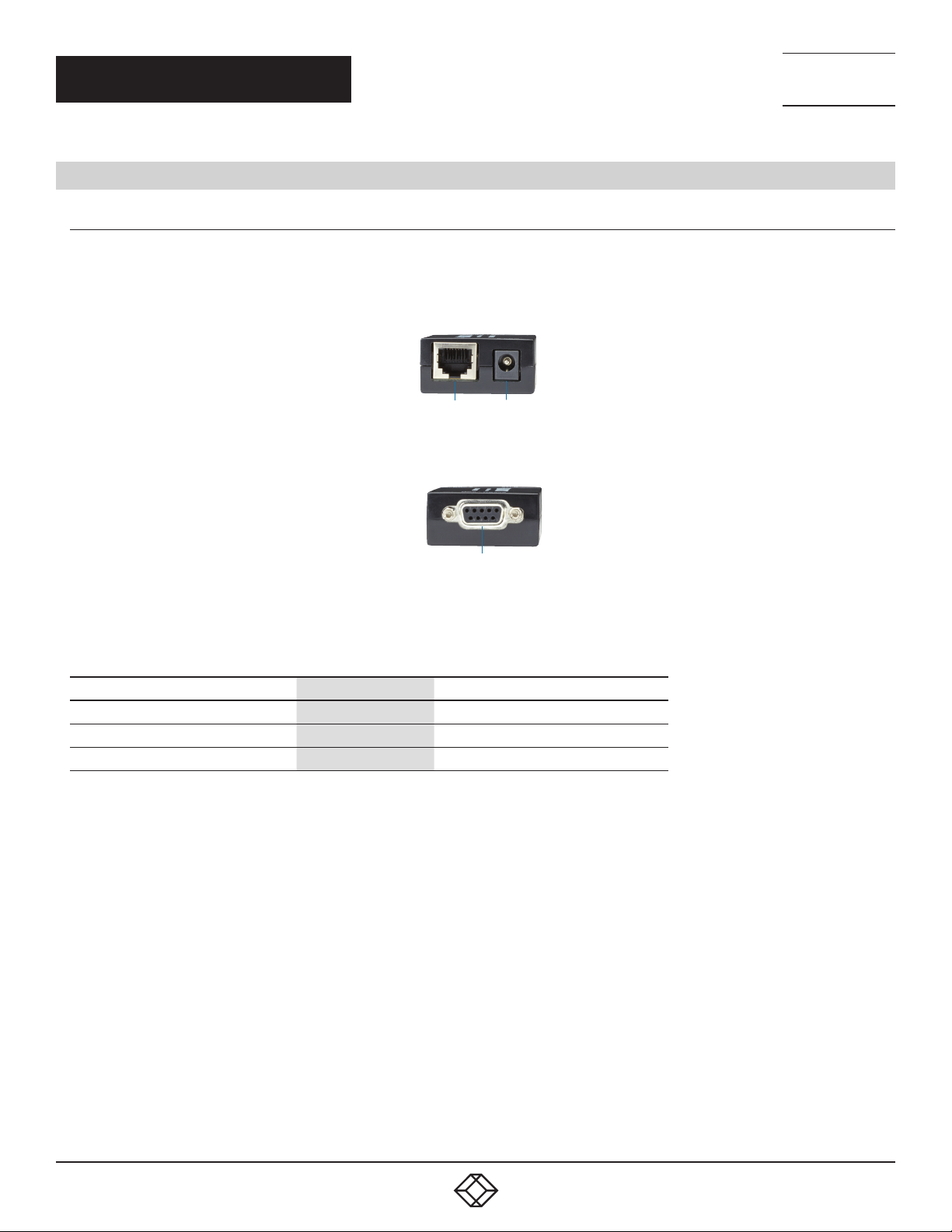
Figure 2-1 shows the local unit’s left-side panel. Figure 2-2 shows its right-side panel. Table 2-1 describes the local unit’s
components pictured in Figures 2-1 and 2-2.
1 2
FIGURE 2-1. LOCAL UNIT’S LEFT-SIDE PANEL
3
FIGURE 2-2. LOCAL UNIT’S RIGHT-SIDE PANEL
TABLE 2-1. LOCAL UNIT’S LEFT- AND RIGHT-SIDE COMPONENTS
NUMBER IN FIGU RES 2-1 AND 2-2 CONNECTION DESCRIPTION
1 RJ-45 connector Connects to remote unit via CATx cable
2 Barrel connector Connects to power supply
3 DB9 female connector Connects to DCE device
1. 8 7 7. 8 7 7. 22 6 9 BL ACK BOX .COM
5
Page 6
NEED HELP?
LEAV E TH E TEC H TO US
LIVE 24/7
CHAPTER 2: OVERVIEW
TECHNICAL
SUPPORT
1. 8 7 7. 8 7 7. 2 2 6 9
2.4.2 REMOTE UNIT
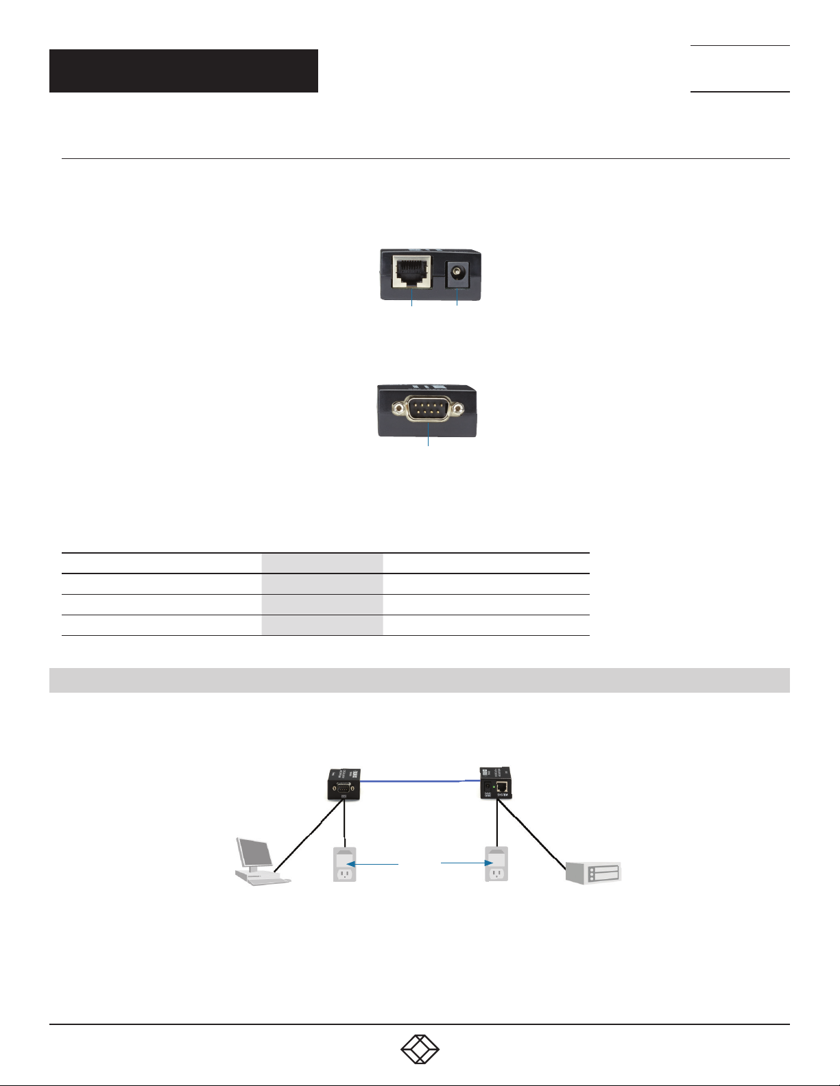
Figure 2-3 shows the remote unit’s left-side panel. Figure 2-4 shows its right-side panel. Table 2-2 describes the remote unit’s
components pictured in Figures 2-3 and 2-4.
1 2
FIGURE 2-3. REMOTE UNIT’S LEFT-SIDE PANEL
3
FIGURE 2-4. REMOTE UNIT’S RIGHT-SIDE PANEL
TABLE 2-2. REMOTE UNIT’S LEFT- AND RIGHT-SIDE COMPONENTS
NUMBER IN FIGU RES 2-3 AND 2-4 CONNECTION DESCRIPTION
1 RJ-45 connector Connects to local unit via CATx cable
2 Barrel connector Connects to power supply
3 DB9 male connector Connects to DTE device
2.5 APPLICATION DIAGRAM
Local Unit
(ME890AE-R2)
Remote Unit
(ME890AE-R2)
5-VDC power
supplies
PC
(DCE device)
Terminal
(DTE device)
FIGURE 2-5. TYPICAL APPLICATION
6
1. 8 7 7. 8 7 7. 22 6 9 BL ACK BOX .COM
Page 7

NEED HELP?
LEAV E TH E TEC H TO US
LIVE 24/7
CH AP TE R 3: I NS TAL LAT IO N
TECHNICAL
SUPPORT
1. 8 7 7. 8 7 7. 2 2 6 9
Before you begin, make sure all equipment is powered off and the CATx DB9 Line Drivers are not powered on.
3.1 INSTALLATION STEPS
Step 1: Connect the local (DB9 female) device to a PC or Data Terminal Equipment (DTE) device.
Step 2: Connect the remote (DB9 male) device to a Data Communication Equipment (DCE) device.
Step 3: Connect the local and remote units with a straight-through CAT5 or CAT6 twisted-pair cable.
Step 4: Once all connections are made, use the supplied 5-VDC power supplies to power up the Line Drivers. Then apply power
to your equipment.
3.2 DB9 PINOUT
TABLE 3-1. DB9 PINOUT
DB9 SIGNAL NUMBER DB9 SIGNAL NAME LOCAL DCE REMOTE DTE
1 Carrier Detect Asserted high No connection
2 Received Data Output Input
3 Transmitted Data Input Output
4 Data Terminal Ready No connection Asserted high
5 Signal Ground RS-232 Ground RS-232 Ground
6 Data Set Ready Asserted high No connection
7 Request To Send Input Output
8 Clear To Send Output Input
9 Ring Indication No connection No connection
NOTES:
DCE = Data Carrier Equipment (can connect to a PC)
DTE = Data Terminal Equipment (configured the same as a PC)
1. 8 7 7. 8 7 7. 22 6 9 BL ACK BOX .COM
7
Page 8
CH AP TE R 3: I NS TAL LAT IO N
3.3 RJ-45 PINOUT
TABLE 3-2. RJ-45 PINOUT
RJ-45 PIN NUMBER RJ-45 SIGNAL NAME LOCAL REMOTE
1 Pair 3+ TXD+ (output) TXD+ (input)
2 Pair 3- TXD- (output) TXD- (input)
3 Pair 2+ RXD+ (input) RXD+ (output)
4 Pair 1+ RTS+ (output) RTS+ (input)
5 Pair 1- RTS- (output) RTS- (input)
6 Pair 2- RXD- (input) RXD- (output)
7 Pair 4+ CTS+ (input) CTS+ (output)
8 Pair 4- CTS- (input) CTS- (output)
9 Shield RS-485 Ground RS-485 Ground
NEED HELP?
LEAV E TH E TEC H TO US
LIVE 24/7
TECHNICAL
SUPPORT
1. 8 7 7. 8 7 7. 2 2 6 9
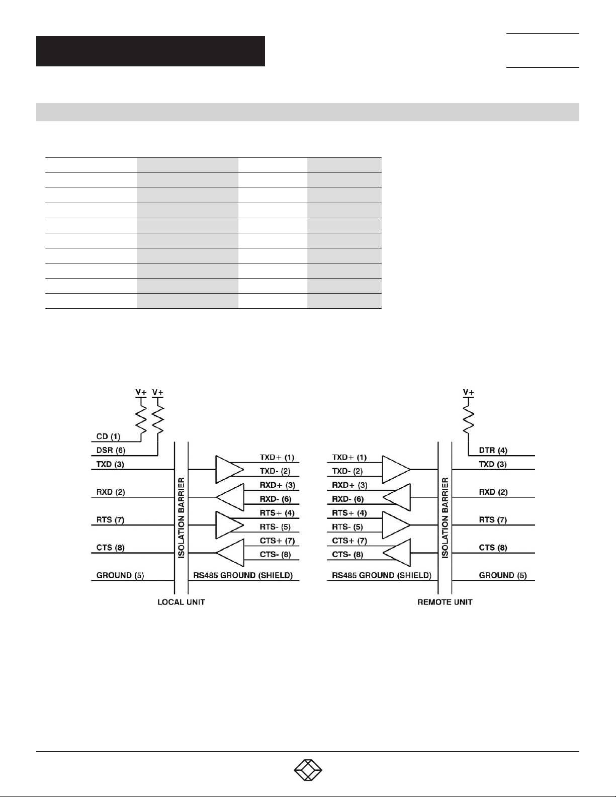
You can use a shielded RJ-45 cable to connect the RS-485 ground between the local and remote units. A shielded cable can reduce
noise, which can improve the RS-485 signals, but can also add capacitance, which can reduce the RS-485 data rate.
FIGURE 3-1. BLOCK DIAGRAM
8
1. 8 7 7. 8 7 7. 22 6 9 BL ACK BOX .COM
Page 9

NEED HELP?
LEAV E TH E TEC H TO US
LIVE 24/7
CHAPTER 4: TROUBLESHOOTING
TECHNICAL
SUPPORT
1. 8 7 7. 8 7 7. 2 2 6 9
4.1 PROBLEMS/SOLUTIONS
If the units fail to operate, check the following before calling for technical support.
1. Are units powered on? Check to see if the power supplies are plugged into a working AC outlet.
2. Check to see if the interconnect wire is connected properly. Use a straight-through CAT5 or CAT6 twisted-pair cable, because the
local and remote units swap transmit and receive pins.
3. Try a lower baud rate if possible to make sure the baud rate is not too fast for the length of cable.
4. Check the DB9 cable connections. The local unit has a DB9 female connector, and is intended for connection to a PC or
data terminal equipment. The remote unit has a DB9 male connector, and is intended for connection to a modem or data
communication equipment.
4.2 CONTACTING BLACK BOX
If you determine that your CATx DB9 Line Driver is malfunctioning, do not attempt to alter or repair the unit. It contains no userserviceable parts. Contact Black Box Technical Support at 724-746-5500 or [email protected].
Before you do, make a record of the history of the problem. We will be able to provide more efficient and accurate assistance if you
have a complete description, including:
the nature and duration of the problem
when the problem occurs
the components involved in the problem
any particular application that, when used, appears to create the problem or make it worse
4.3 SHIPPING AND PACKAGING
If you need to transport or ship your CATx DB9 Line Driver:
Package it carefully. We recommend that you use the original container.
If you are returning the unit, make sure you include everything you received with it. Before you ship for return or repair,
contact Black Box to get a Return Authorization (RA) number.
1. 8 7 7. 8 7 7. 22 6 9 BL ACK BOX .COM
9
Page 10

NEED HELP?
LEAV E TH E TEC H TO US
LIVE 24/7
APPENDIX: REGULATORY INFORMATION
TECHNICAL
SUPPORT
1. 8 7 7. 8 7 7. 2 2 6 9
A.1 FCC STATEMENT
This equipment generates, uses, and can radiate radio-frequency energy, and if not installed and used properly, that is, in strict
accordance with the manufacturer’s instructions, may cause inter ference to radio communication. It has been tested and found to
comply with the limits for a Class A computing device in accordance with the specifications in Subpart B of Part 15 of FCC rules,
which are designed to provide reasonable protection against such interference when the equipment is operated in a commercial
environment. Operation of this equipment in a residential area is likely to cause interference, in which case the user at his own
expense will be required to take whatever measures may be necessary to correct the interference.
Changes or modifications not expressly approved by the party responsible for compliance could void the user’s authority to operate
the equipment.
This digital apparatus does not exceed the Class A limits for radio noise emis sion from digital apparatus set out in the Radio
Interference Regulation of Industry Canada.
Le présent appareil numérique n’émet pas de bruits radioélectriques dépassant les limites applicables aux appareils numériques
de classe A prescrites dans le Règlement sur le brouillage radioélectrique publié par Industrie Canada.
10
1. 8 7 7. 8 7 7. 22 6 9 BL ACK BOX .COM
Page 11

NEED HELP?
LEAV E TH E TEC H TO US
LIVE 24/7
APPENDIX: REGULATORY INFORMATION
TECHNICAL
SUPPORT
1. 8 7 7. 8 7 7. 2 2 6 9
A.2 NOM STATEMENT
1. Todas las instrucciones de seguridad y operación deberán ser leídas antes de que el aparato eléctrico sea operado.
2. Las instrucciones de seguridad y operación deberán ser guardadas para referencia futura.
3. Todas las advertencias en el aparato eléctrico y en sus instrucciones de operación deben ser respetadas.
4. Todas las instrucciones de operación y uso deben ser seguidas.
5. El aparato eléctrico no deberá ser usado cerca del agua—por ejemplo, cerca de la tina de baño, lavabo, sótano mojado o cerca
de una alberca, etc.
6. El aparato eléctrico debe ser usado únicamente con carritos o pedestales que sean recomendados por el fabricante.
7. El aparato eléctrico debe ser montado a la pared o al techo sólo como sea recomendado por el fabricante.
8. Servicio—El usuario no debe intentar dar servicio al equipo eléctrico más allá a lo descrito en las instrucciones de operación.
Todo otro servicio deberá ser referido a personal de servicio calificado.
9. El aparato eléctrico debe ser situado de tal manera que su posición no interfiera su uso. La colocación del aparato eléctrico
sobre una cama, sofá, alfombra o superficie similar puede bloquea la ventilación, no se debe colocar en libreros o gabinetes que
impidan el flujo de aire por los orificios de ventilación.
10. El equipo eléctrico deber ser situado fuera del alcance de fuentes de calor como radiadores, registros de calor, estufas u otros
aparatos (incluyendo amplificadores) que producen calor.
11. El aparato eléctrico deberá ser connectado a una fuente de poder sólo del tipo descrito en el instructivo de operación, o como
se indique en el aparato.
12. Precaución debe ser tomada de tal manera que la tierra fisica y la polarización del equipo no sea eliminada.
13. Los cables de la fuente de poder deben ser guiados de tal manera que no sean pisados ni pellizcados por objetos colocados
sobre o contra ellos, poniendo particular atención a los contactos y receptáculos donde salen del aparato.
14. El equipo eléctrico debe ser limpiado únicamente de acuerdo a las recomendaciones del fabricante.
15. En caso de existir, una antena externa deberá ser localizada lejos de las lineas de energia.
16. El cable de corriente deberá ser desconectado del cuando el equipo no sea usado por un largo periodo de tiempo.
17. Cuidado debe ser tomado de tal manera que objectos liquidos no sean derramados sobre la cubierta u orificios de ventilación.
18. Servicio por personal calificado deberá ser provisto cuando:
A: El cable de poder o el contacto ha sido dañado; u
B: Objectos han caído o líquido ha sido derramado dentro del aparato;o
C: El aparato ha sido expuesto a la lluvia; o
D: El aparato parece no operar normalmente o muestra un cambio en su desempeño; o
E: El aparato ha sido tirado o su cubierta ha sido dañada.
1. 8 7 7. 8 7 7. 22 6 9 BL ACK BOX .COM
11
Page 12

TRADEMARKS USED IN THIS MANUAL
Black Box and the Double Diamond logo are registered trademarks of BB Technologies, Inc.
Any other trademarks mentioned in this manual are acknowledged to be the property of the trademark owners.
NEED HELP?
LEAV E TH E TEC H TO US
LIVE 24/7
TECHNICAL
SUPPORT
1. 8 7 7. 8 7 7. 2 2 6 9
12
1. 8 7 7. 8 7 7. 22 6 9 BL ACK BOX .COM
Page 13

NOTES
__________________________________________________________________________________________________
__________________________________________________________________________________________________
__________________________________________________________________________________________________
__________________________________________________________________________________________________
__________________________________________________________________________________________________
__________________________________________________________________________________________________
NEED HELP?
LEAV E TH E TEC H TO US
LIVE 24/7
TECHNICAL
SUPPORT
1. 8 7 7. 8 7 7. 2 2 6 9
__________________________________________________________________________________________________
__________________________________________________________________________________________________
_
_________________________________________________________________________________________________
__________________________________________________________________________________________________
__________________________________________________________________________________________________\
__________________________________________________________________________________________________
__________________________________________________________________________________________________
__________________________________________________________________________________________________
__________________________________________________________________________________________________
__________________________________________________________________________________________________
__________________________________________________________________________________________________
__________________________________________________________________________________________________
1. 8 7 7. 8 7 7. 22 6 9 BL ACK BOX .COM
13
Page 14

NOTES
__________________________________________________________________________________________________
__________________________________________________________________________________________________
__________________________________________________________________________________________________
__________________________________________________________________________________________________
__________________________________________________________________________________________________
__________________________________________________________________________________________________
NEED HELP?
LEAV E TH E TEC H TO US
LIVE 24/7
TECHNICAL
SUPPORT
1. 8 7 7. 8 7 7. 2 2 6 9
__________________________________________________________________________________________________
_
_________________________________________________________________________________________________
__________________________________________________________________________________________________
__________________________________________________________________________________________________\
__________________________________________________________________________________________________
__________________________________________________________________________________________________
__________________________________________________________________________________________________
__________________________________________________________________________________________________
_________________________________________________________________________________________________
14
__________________________________________________________________________________________________
__________________________________________________________________________________________________
__________________________________________________________________________________________________
1. 8 7 7. 8 7 7. 22 6 9 BL ACK BOX .COM
Page 15

NOTES
__________________________________________________________________________________________________
__________________________________________________________________________________________________
__________________________________________________________________________________________________
__________________________________________________________________________________________________
__________________________________________________________________________________________________
_
_________________________________________________________________________________________________
NEED HELP?
LEAV E TH E TEC H TO US
LIVE 24/7
TECHNICAL
SUPPORT
1. 8 7 7. 8 7 7. 2 2 6 9
__________________________________________________________________________________________________
__________________________________________________________________________________________________\
__________________________________________________________________________________________________
__________________________________________________________________________________________________
__________________________________________________________________________________________________
__________________________________________________________________________________________________
__________________________________________________________________________________________________
________________________________________________________________________________________________
________________________________________________________________________________________________
__________________________________________________________________________________________________
__________________________________________________________________________________________________
__________________________________________________________________________________________________
1. 8 7 7. 8 7 7. 22 6 9 BL ACK BOX .COM
15
Page 16

NEED HELP?
LEAVE THE TECH TO US
LIVE 24/7
TECHNICAL
SUPPORT
1.87 7. 8 77.22 69
© COPYRIGHT 2021 BLACK BOX CORPORATION. ALL RIGHTS RESERVED.
 Loading...