

Black Box ME806A, ME806-C, ME807A, ME807-C, SHM-B Parallel-T Installation Instructions Manual
...Page 1
CUSTOMER
SUPPORT
INFORMATION
Order toll-free in the U.S.: Call 877-877-BBOX (outside U.S. call 724-746-5500)
FREE technical support 24 hours a day, 7 days a week: Call 724-746-5500 or fax 724-746-0746
Mailing address: Black Box Corporation, 1000 Park Drive, Lawrence, PA 15055-1018
Web site: www.blackbox.com • E-mail: info@blackbox.com
SEPTEMBER 2001
ME806A
ME806-C
ME807A
ME807-C
SHM-B Parallel-T
SHM-B Parallel-T Card
SHM-B Parallel-R
SHM-B Parallel-R Card
Page 2

1
FCC AND IC RFI STATEMENTS
FEDERAL COMMUNICATIONS COMMISSION AND INDUSTRY CANADA
RADIO-FREQUENCY INTERFERENCE STATEMENTS
This equipment generates, uses, and can radiate radio-frequency energy and, if not
installed and used properly, that is, in strict accordance with the manufacturer’s
instructions, may cause interference to radio communication. It has been tested
and found to comply with the limits for a Class A computing device in accordance
with the specifications in Subpart J of Part 15 of FCC rules, which are designed to
provide reasonable protection against such interference when the equipment is
operated in a commercial environment. Operation of this equipment in a
residential area is likely to cause interference, in which case the user at his own
expense will be required to take whatever measures may be necessary to correct
the interference.
Changes or modifications not expressly approved by the party responsible
for compliance could void the user’s authority to operate the equipment.
This digital apparatus does not exceed the Class A limits for radio noise emission from
digital apparatus set out in the Radio Interference Regulation of Industry Canada.
Le présent appareil numérique n’émet pas de bruits radioélectriques dépassant les limites
applicables aux appareils numériques de la classe A prescrites dans le Règlement sur le
brouillage radioélectrique publié par Industrie Canada.
Page 3

2
SHM-B PARALLEL-T, SHM-B PARALLEL -R
NORMAS OFICIALES MEXICANAS (NOM)
ELECTRICAL SAFETY STATEMENT
INSTRUCCIONES DE SEGURIDAD
1. Todas las instrucciones de seguridad y operación deberán ser leídas antes de
que el aparato eléctrico sea operado.
2. Las instrucciones de seguridad y operación deberán ser guardadas para
referencia futura.
3. Todas las advertencias en el aparato eléctrico y en sus instrucciones de
operación deben ser respetadas.
4. Todas las instrucciones de operación y uso deben ser seguidas.
5. El aparato eléctrico no deberá ser usado cerca del agua—por ejemplo, cerca
de la tina de baño, lavabo, sótano mojado o cerca de una alberca, etc..
6. El aparato eléctrico debe ser usado únicamente con carritos o pedestales que
sean recomendados por el fabricante.
7. El aparato eléctrico debe ser montado a la pared o al techo sólo como sea
recomendado por el fabricante.
8. Servicio—El usuario no debe intentar dar servicio al equipo eléctrico más allá
a lo descrito en las instrucciones de operación. Todo otro servicio deberá ser
referido a personal de servicio calificado.
9. El aparato eléctrico debe ser situado de tal manera que su posición no
interfiera su uso. La colocación del aparato eléctrico sobre una cama, sofá,
alfombra o superficie similar puede bloquea la ventilación, no se debe colocar
en libreros o gabinetes que impidan el flujo de aire por los orificios de
ventilación.
10. El equipo eléctrico deber ser situado fuera del alcance de fuentes de calor
como radiadores, registros de calor, estufas u otros aparatos (incluyendo
amplificadores) que producen calor.
11. El aparato eléctrico deberá ser connectado a una fuente de poder sólo del
tipo descrito en el instructivo de operación, o como se indique en el aparato.
Page 4

3
NOM STATEMENT
12. Precaución debe ser tomada de tal manera que la tierra fisica y la polarización
del equipo no sea eliminada.
13. Los cables de la fuente de poder deben ser guiados de tal manera que no
sean pisados ni pellizcados por objetos colocados sobre o contra ellos,
poniendo particular atención a los contactos y receptáculos donde salen del
aparato.
14. El equipo eléctrico debe ser limpiado únicamente de acuerdo a las
recomendaciones del fabricante.
15. En caso de existir, una antena externa deberá ser localizada lejos de las lineas
de energia.
16. El cable de corriente deberá ser desconectado del cuando el equipo no sea
usado por un largo periodo de tiempo.
17. Cuidado debe ser tomado de tal manera que objectos liquidos no sean
derramados sobre la cubierta u orificios de ventilación.
18. Servicio por personal calificado deberá ser provisto cuando:
A: El cable de poder o el contacto ha sido dañado; u
B: Objectos han caído o líquido ha sido derramado dentro del aparato; o
C: El aparato ha sido expuesto a la lluvia; o
D: El aparato parece no operar normalmente o muestra un cambio en su
desempeño; o
E: El aparato ha sido tirado o su cubierta ha sido dañada.
TRADEMARKS USED IN THIS MANUAL
BLACK BOX and the logo are registered trademarks of Black Box
Corporation.
IBM, PC/AT, and PS/2 are registered trademarks, and PC/XT is a trademark, of
International Business Machines Corporation.
Any other trademarks mentioned in this manual are acknowledged to be the property of the
trademark owners.
Page 5

4
SHM-B PARALLEL-T, SHM-B PARALLEL -R
Contents
Chapter Page
1. Specifications....................................................................................................5
2. Introduction .....................................................................................................7
3. Installation....................................................................................................... 9
3.1 Standalone and Rackmount Versions .....................................................9
3.2 Connectors ................................................................................................9
3.3 Installation Procedure ..............................................................................9
3.4 LED Indicators ........................................................................................13
3.5 Rack Mounting........................................................................................14
3.6 Configuration..........................................................................................14
4. Troubleshooting ............................................................................................16
Page 6
5
CHAPTER 1: Specifications
1. Specifications
Models: ME806A, SHM-B Parallel-T (standalone transmitter)
ME806-C, SHM-B Parallel-T (rackmount transmitter)
ME807A, SHM-B Parallel-R (standalone receiver)
ME807-C, SHM-B Parallel-R (rackmount receiver)
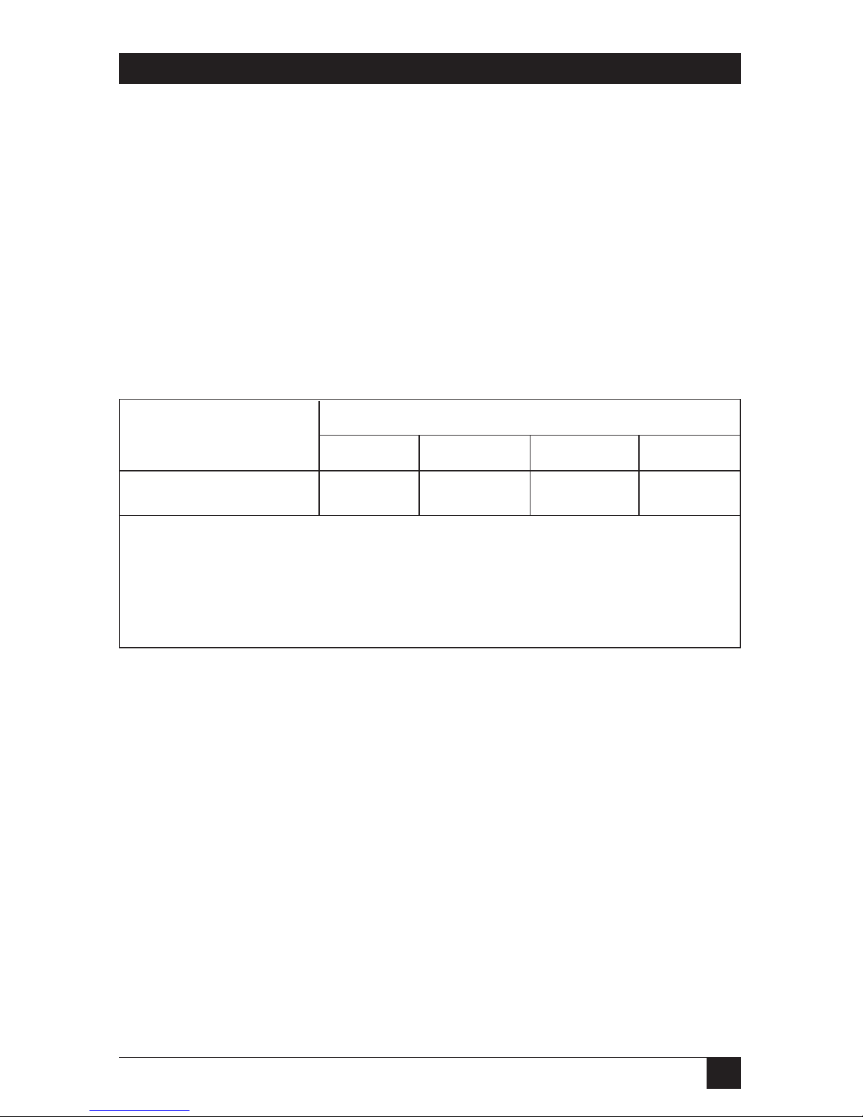
Transmission Distance:
Bit Rate (bps)
2400 4800 9600 19.2 kbps
Distance (miles) 5 3 2 1.1
NOTE
These specifications are valid for unshielded twisted-pair telephone cable
having 24 or 26 AWG connectors. Shielded twisted-pair cable will reduce
the distance to
1
⁄3
of the table value.
Line Interface: Proprietary balanced 4-wire
Indicators: RD and TD Green and Red = Data transmission.
Green = Mark (idle state).
Red = Error condition. Check cabling.
BUSY Red = Printer is not online or not ready to
receive data.
Off = Printer is ready to receive data and
cabling is installed correctly.
Connectors: Transmitter DB25 male, 4-screw terminal block
Receiver DB25 female, 4-screw terminal block
Enclosure: High-impact ABS plastic
Page 7

6
SHM-B PARALLEL-T, SHM-B PARALLEL -R
Operating
Temperature: 32 to 112°F (0 to 45°C)
Operating
Humidity: 95% relative humidity, noncondensing
Power: 120 VAC ±10%, 60 Hz, 1 watts, wallmount
transformer (230 VAC ±10%, 50/60-Hz option available)
Size: 1.5"H x 4.3"W x 4.6"D (3.8 x 10.9 x 11.7 cm)
Weight: 1.3 lb. (0.6 kg) with transformer
Page 8

7
CHAPTER 2: Introduction
2. Introduction
The SHM-B Parallel performs three functions:
• The SHM-B Parallel-T accepts parallel data from the PC, converts it to serial
data, and sends the serial data over twisted-pair cable to the SHM-B Parallel-R.
The SHM-B Parallel-R receives the serial data, converts it back to parallel data,
and sends it to the the parallel printer.
• The SHM-B Parallel-T accepts parallel data from the PC, converts it to serial
data, and sends the serial data over twisted-pair cable to the SHM-B. The SHMB receives the serial data, converts it to RS-232 specifications, and sends the
data to the RS-232 serial printer.
• The SHM-B accepts the RS-232 data from the PC, converts it to serial data, and
sends it over the twisted-pair cable to the SHM-B Parallel-R. The SHM-B
Parallel-R receives the serial data, converts it to parallel data, and sends it to
the parallel printer.
4-wire cable
Serial input
from PC
Parallel output
to printer
SHM-B Parallel-T
(ME806A)
SHM-B Parallel-R
(ME807A)
4-wire cable
Parallel input
Serial output
SHM-B Parallel-T
(ME806A)
SHM-B
(ME800A-R2)
4-wire cable
Serial input
from PC
Parallel output
to printer
SHM-B
(ME800A-R2)
SHM-B Parallel-R
(ME807A)
Page 9

8
SHM-B PARALLEL-T, SHM-B PARALLEL -R
The SHM-B Parallel performs data transmission at bit rates from 1200 to 19,200
baud. It can be configured for either 7- or 8-bit word length and Even, Odd, or
No parity. The SHM-B Parallel features advanced optically-isolated integrated
circuitry, which eliminates damaging ground-loop currents and substantially
reduces signal noise for improved data integrity.
The SHM-B Parallel transmitter/receiver pair requires only two twisted-pair wires
to transmit and receive data. Optimum performance is obtained with 24 or 26
AWG twisted-pair telephone cable, but nearly any twisted-pair cable can be used
with little or no performance degradation.
NOTE
When operating serial to parallel or parallel to serial, the serial device has
to run hardware flow control. Software flow control (X-ON/X-OFF, etc.) is
not supported.
Page 10

9
CHAPTER 3: Installation
3. Installation
3.1 Standalone and Rackmount Versions
The SHM-B Parallel is available in a standalone version and a rackmount version.
The standalone transmitter and receiver are packaged in small, lightweight ABS
plastic cases and equipped with wallmount transformers, for use on a desktop or
shelf. The printed circuit card can be removed from the case and the transformer
discarded, enabling the card to be installed in a rack if desired. The rackmount
version slips easily into an 8- or 16-card rack or enclosure.
3.2 Connectors
Each unit is equipped with a DB25 connector and a 4-wire terminal block.
The DB25 connector conforms to the IBM
®
PC parallel interface pinout, using
the Centronics
®
interface protocol. The 4-wire terminal block is the serial interface
to the twisted-pair line.
3.3 Installation Procedure
Before installing the receiver or transmitter, make certain the unit is not plugged
into the power source, and the equipment that you are going to attach to them is
turned off.
Each unit is ready to use as it comes from the factory. No changes are necessary
when used as a modem set to transmit data from a parallel device to another
parallel device at distances of up to 1.1 mile (1.8 kg). However, for installations in
which the loop length exceeds 1.1 mile, data corruption may occur due to
excessive line noise and/or capacitance. In this case, reduce the transmission baud
rate, using the configuration procedure described in Section 3.6.
Installation is accomplished in the following three steps:
1. Connect Cabling
For installation, connect a 4-wire twisted-pair cable between the transmitter and
the receiver.
Page 11

10
SHM-B PARALLEL-T, SHM-B PARALLEL -R
Remove the SHM-B card from the case or rack, exposing the terminal connector
on the card. (For instructions on opening the standalone unit’s case, see step 2 in
Section 3.6.) Strip
1
⁄8 to 3⁄16 inch of the insulation from the end of all four of the
cable wires. Insert the wires into the terminal block and tighten the screw
terminals. Depending on your application, connect the terminals on the
transmitter to the terminals on the receiver as shown in Figure 3-1, 3-2, or 3-3.
Figure 3-1. Parallel-to-Parallel Installation
Figure 3-2. Serial-to-Parallel Installation
When you have made the connections, thread the nylon cable tie (provided)
through the tie-down holes in the card and around the wires. Pull tightly until the
cable tie has secured the wires to the card. Remove the excess tie.
SHM-B
TRANSMITTER
SHM-B PARALLEL-R
RECEIVER
SHM-B PARALLEL-T
TRANSMITTER
SHM-B PARALLEL-R
RECEIVER
Page 12

11
CHAPTER 3: Installation
Figure 3-3. Parallel-to-Serial Installation
NOTE
When operating serial to parallel or parallel to serial, the serial device has
to run hardware flow control. Software flow control (X-ON/X-OFF, etc.) is
not supported.
2. Test the Cabling
To test the 4-wire cable and connections, remove the cable connecting the PC
to the transmitter. When the modems are turned on, the following LED display
should be seen:
TD on the transmitter will light green;
RD on the receiver will light green;
BUSY will not light on either unit.
3. Connect Your PC and Printer
The parallel interface on the SHM-B Parallel and on IBM PC/XT™, PC/AT
®
,
PS/2
®
, and compatibles is similar to the Centronics standard, but uses a DB25
connector instead of a 36-pin Centronics connector. To connect these devices to
the SHM-Parallel, use a 25-pin straight-through cable with a DB25 female
connector on the SHM-B Parallel transmitter side and a DB25 male connector on
the PC side.
SHM-B PARALLEL-T
TRANSMITTER
SHM-B
RECEIVER
Page 13

12
SHM-B PARALLEL-T, SHM-B PARALLEL -R
Figure 3-4. IBM PC to Printer Connection
If your PC or other device (such as a mainframe computer) has a Centronics
connector on the parallel output port, use the Centronics-to-DB25 female cable
described in Table 3-1 to connect to the SHM-B Parallel transmitter.
Figure 3-5. Mainframe-to-Printer Connection
Use a DB25 male-to-Centronics cable described in Table 3-1 to connect the
SHM-B Parallel receiver to any parallel device equipped with a Centronics
connector.
NOTE
The standard genders for EYN600 are DB25 male to Centronics male. To
use with the mainframe as shown in the above diagram, specify EYN600
with a DB25 female and a Centronics male when ordering the cable.
When your cables are connected, no change in the LEDs will occur until data
transmission begins, and then the TD and RD LEDs should light green and red
simultaneously.
25-Pin Straight-Through
Cable (ECM25C)
DB25
Connector
IBM PC
SHM-B Parallel-T
SHM-B Parallel-R
Centronics
Connector
Printer
PC/Centronics Cable
(EYN600)
4-Wire
Twisted-Pair
Mainframe
SHM-B Parallel-T
SHM-B Parallel-R
Printer
4-Wire
Centronics
Connectors
PC/Centronics Cable
(EYN600)
PC/Centronics Cable
(EYN600)
Centronics
Connectors
Page 14

13
CHAPTER 3: Installation
Table 3-1. Centronics Parallel Adapter Cable
25-Pin DB25 36-Pin Centronics
Signal Connector Pin # Connector Pin #
STROBE 1 - - - - - - - - - - - - - - - - - - - - - - - -1
DATA 1 2 - - - - - - - - - - - - - - - - - - - - - - - -2
DATA 2 3 - - - - - - - - - - - - - - - - - - - - - - - -3
DATA 3 4 - - - - - - - - - - - - - - - - - - - - - - - -4
DATA 4 5 - - - - - - - - - - - - - - - - - - - - - - - -5
DATA 5 6 - - - - - - - - - - - - - - - - - - - - - - - -6
DATA 6 7 - - - - - - - - - - - - - - - - - - - - - - - -7
DATA 7 8 - - - - - - - - - - - - - - - - - - - - - - - -8
DATA 8 9 - - - - - - - - - - - - - - - - - - - - - - - -9
ACKNOWLEDGE 10 - - - - - - - - - - - - - - - - - - - - - - - -10
BUSY 11 - - - - - - - - - - - - - - - - - - - - - - - -11
PAPER END 12 - - - - - - - - - - - - - - - - - - - - - - - -12
SELECT 13 - - - - - - - - - - - - - - - - - - - - - - - -13
AUTO FEED 14 - - - - - - - - - - - - - - - - - - - - - - - -14
PRIME 15 - - - - - - - - - - - - - - - - - - - - - - - -32
FAULT 16 - - - - - - - - - - - - - - - - - - - - - - - -31
SELECT IN 17 - - - - - - - - - - - - - - - - - - - - - - - -36
GROUND 18 - - - - - - - - - - - - - - - - - - - - - - - -33
DATA 1 RTN 19 - - - - - - - - - - - - - - - - - - - - - - - -19
GROUND 20 - - - - - - - - - - - - - - - - - - - - - - - -21
GROUND 21 - - - - - - - - - - - - - - - - - - - - - - - -23
GROUND 22 - - - - - - - - - - - - - - - - - - - - - - - -25
GROUND 23 - - - - - - - - - - - - - - - - - - - - - - - -27
GROUND 24 - - - - - - - - - - - - - - - - - - - - - - - -29
GROUND 25 - - - - - - - - - - - - - - - - - - - - - - - -30
3.4 LED Indicators
The SHM-B Parallel-T has two status indicators:
TD (Transmit Data) indicates data signal activity
BUSY indicates flow control signal activity
The SHM-B Parallel-R has two status indicators:
RD (Receive Data) indicates data signal activity
BUSY indicates flow control signal activity
Page 15

14
SHM-B PARALLEL-T, SHM-B PARALLEL -R
In the idle condition, the TD and the RD LEDs will light green. When
transmitting, they will light green and red. When the printer cannot accept
any more data, the Busy LED on the transmitter and on the receiver will light
red and the data transmission will stop.
When used for serial-to-parallel data conversion, the Busy LED on the receiver
will light to indicate that the device connected to its parallel port is not ready to
receive data.
3.5 Rack Mounting
The rackmount version will occupy 5.25 inches of vertical rack space.
Connect the cabling to each card according to the procedures in Section 3.3. It
is usually easier to feed all of the necessary wires and cables through the rack, then
work with the cards in front of the rack to make the connections. After each card is
wired, it can be inserted into an open slot in the rack. Be certain that the card has
mated with the power pins on the rack before applying force to fully seat the
board; otherwise damage to the card and power pins can result.
When all cards have been wired and plugged into the rack, plug the wall
transformer into its power source.
3.6 Configuration
The SHM-B Parallel can be configured to transmit serial data streams at baud rates
from 1200 to 19,200 bps with 7- or 8-bit word length and Even, Odd, or No parity.
The SHM-B Parallel-R is hardwired for either 1 or 2 stop bits, the transmitter for
2 stop bits. The factory setting is 19,200 baud, 8-bit word length, and No parity.
If you experience signal degradation over long loop distances, you must
reconfigure the SHM-B Parallel to a slower baud rate. Always configure the
transmitter and receiver the same.
The configuration switches are all contained in a single block of DIP switches.
The switch block is located on the printed circuit card, and is labeled SW1.
After removing the card from the case or rack, locate the switch block on the card.
Refer to Figure 3-6 for assistance locating the switch block. To attain the desired
switch settings, follow the steps below:
1. Disconnect the unit from the power supply.
2. Remove the unit from the card rack or standalone case. The standalone
version of both models is shipped assembled in the case with the faceplate
Page 16

15
CHAPTER 3: Installation
installed. To remove the faceplate and expose the card, apply pressure at the
top front of the unit to separate the top and the bottom halves of the case,
then push on the rear connector to force out the front panel and printed
circuit assembly.
Figure 3-6. SHM-B Parallel Component Layout
3. Locate the baud-rate selector switches. The baud-rate options are 1200, 2400,
4800, 9600, and 19,200 bps. Only one baud-rate selection is permissible. Press
the rocker switch down to the right to select the desired baud rate. When a
switch is pressed down on the left, it is in the Off position.
4. Locate the Word Length selector switch labeled 8-7B. Press down on the left
side of the switch to select 8-bit word length; on the right to select 7-bit word
length.
5. Locate the Parity Enable/Disable selector switch labeled NP-P. Press down on
the right side of the switch to enable parity (P); on the left to disable (NP).
6. Locate the Even/Odd Parity selector switch labeled E-O. When the NP-P
switch is in the NP position, the E-O switch has no effect. This switch is
enabled by the Parity Enable/Disable selector switch. When parity is enabled,
press the switch down on the left to select Even parity; on the right to select
Odd parity.
Switch block
DB25 Connector
Tie Downs
Rackmount Power
Connectors
Terminal Block
LEDs
Page 17

16
SHM-B PARALLEL-T, SHM-B PARALLEL -R
4. Troubleshooting
Before installing the SHM-B Parallel, verify that the source of the parallel data
works correctly with the destination equipment when no modem link is installed.
This isn’t always possible, but be certain that all equipment is plugged-in and
powered on, and that all cables are securely connected. The most likely problems
and their causes are discussed below.
No data transfer
1. Incorrect wiring on the 4-wire circuit. See Figures 3-1 through 3-3. When the
lines are properly connected, both the TD and the RD LED on the units will
light Green in the idle state.
2. Incorrect baud rate, parity, or word length settings.
3. Distance/baud rate recommendations exceeded. Refer to Chapter 1 to
determine recommended loop distance and baud rates.
4. Printer is off-line (Busy LED is lit red).
Garbled data (all data erroneous)
1. Incorrect wiring on the 4-wire circuit (wrong polarity).
2. Incorrect baud rate, parity, or word length settings.
Occasional data errors
1. Distance/baud rate capacity exceeded.
2. Poor quality loop (4-wire circuit); try different circuit or wire, try lower baud rate.
3. Excessive signal noise or crosstalk on the loop.
4. Marginal AC power source; check transformer output.
Busy LED stays on
1. Printer off-line or not operational.
2. Incorrect wiring on the 4-wire circuit (wrong polarity).
Page 18

1000 Park Drive • Lawrence, PA 15055-1018 • 724-746-5500 • Fax 724-746-0746
© Copyright 2001. Black Box Corporation. All rights reserved.
 Loading...