

Page 1
RXB
Power Supply part # PS154
RXA
TXB
TXA
A B C D E
160 msec.
11 msec.
50 msec.
0 msec. RTS/CTS
S7
OFF Constant Carrier
1 2
ON
W3
Half Full
ON
OFF
S4
1 2 3 4
S5
1 2 3 4 5 6 7 8
BAUD RATE
SETTINGS
ON
OFF
Power
RD
TD
CD
RTS
INTRODUCTION:
The RS-232 Synchronous Multipoint Line Driver provides short haul synchronous data communication over customerowned twisted-pair cable. The Line Driver is available as a standalone (Part Number ME742A-R3) or a rackmount card
(Part Number ME742C-R3). The rackmount version is functionally identical to the standalone unit. The card can be
installed in a rackmount chassis that holds up to 16 cards (Part Number RM005).
The Line Driver has an RS-232 port (configured as DCE) that connects to a host computer or terminal (DTE), and a 4screw terminal block for RS-485 communication over a 2- or 4-wire line. Transmission can be two-wire half-duplex, or
four-wire half- or full-duplex. There are a variety of switch-selectable baud rates ranging from 1200 to 128000 bps.
A group of LED's on the unit's front panel indicate flow control status (TX, RX, RTS, CD). Three push-buttons on the
front panel are used to perform line and digital loopback testing. A number of options are configurable via internal switches
or jumpers.
INSTALLATION:
DB25
Female
Conn.
S6
ON
OFF
1 2 3 4
TRANSMIT
CLOCK
SELECT
SPECIFICATIONS:
ME742A-R3
Terminal Interface: EIA RS-232-C configured as DCE serial synchronous internal/external/
recovered TX data clock.
Line Interface: EIA-RS-485 twisted pair (26 AWG minimum), DC continuity required.
Connectors: (1) DB25 female-RS-232 port; (1) four-wire terminal block (TB1)-RS-485 port.
Operation: Point-to-Point or Multi-point; Full- or Half-Duplex Transparent to data. Selectable
RTS-to-CTS delay, DTE or DCE configurable RS-232 port, Normal or loopback
operation.
Timeout Delay: 1 msec, 100 msec, or 1 sec. (for the RS-485 driver enabled by data feature)
Pins Supported: RS-232 port: TD,RD, RTS, CTS, CD, DTR, DSR, SG, TC RC, DTE timing,
AND FG;
RS-485 port: TXA, TXB, RXA, RXB
Operating Modes: 2-wire half duplex, 4-wire full or half duplex point-to-point or multipoint,
Normal or line/digital loopback; Constant Carrier or Switched Mode.
Data Rate: 1200, 2400, 4800, 9600, 19200, 38400, 56000, 64000, 112000, or 128000 bps.
RTS/CTS Delay: 0, 11, 50, or 160 msec.
Indicators: (5) LED's: TX, RX, RTS, CD and PWR.
Power: Input - 115 VAC, 60 Hz, 8.5 watts. Output - 17 VAC CT, 700 ma.
TST
LLB
DLB
SPEED DISTANCE
1200 bps 4 mi. (6.4 km)
2400 bps 3 mi. (4.8 km)
4800 bps 2.3 mi. (3.7km)
9600 bps 1.7 mi. (2.7km)
19,200 bps 1.2 mi. (1.9km)
38,400 bps .9 mi. (1.4km)
56,000 bps .8 mi. (1.2 km)
64,000 bps
112,000 bps
128,000 bps
.75 mi. (1.2km)
.55 mi. (.88km)
.35 mi. (.56km)
Proceed as follows to install to Line Drivers:
1. Configure the Line Driver to suit your particular application.
2. To verify that the Line Driver is functioning correctly, power on the unit and perform the Line Loopback Test.
Repeat this procedure for each unit in your configuration.
3. Power down the unit. Connect the Line Driver to the RS-485 line via the 4-screw terminal block on the unit's
rear panel.
4. To verify the communications link, power on the unit and perform the Digital Loopback Test.
5. Power off the unit. Connect the DTE to the Line Driver's DB25 connector via an RS-232 cable.
6. If desired, power on the unit and perform the End-to-End Continuity Test to verify the integrity of each
segment of the link. This test allows you to isolate a defective circuit.
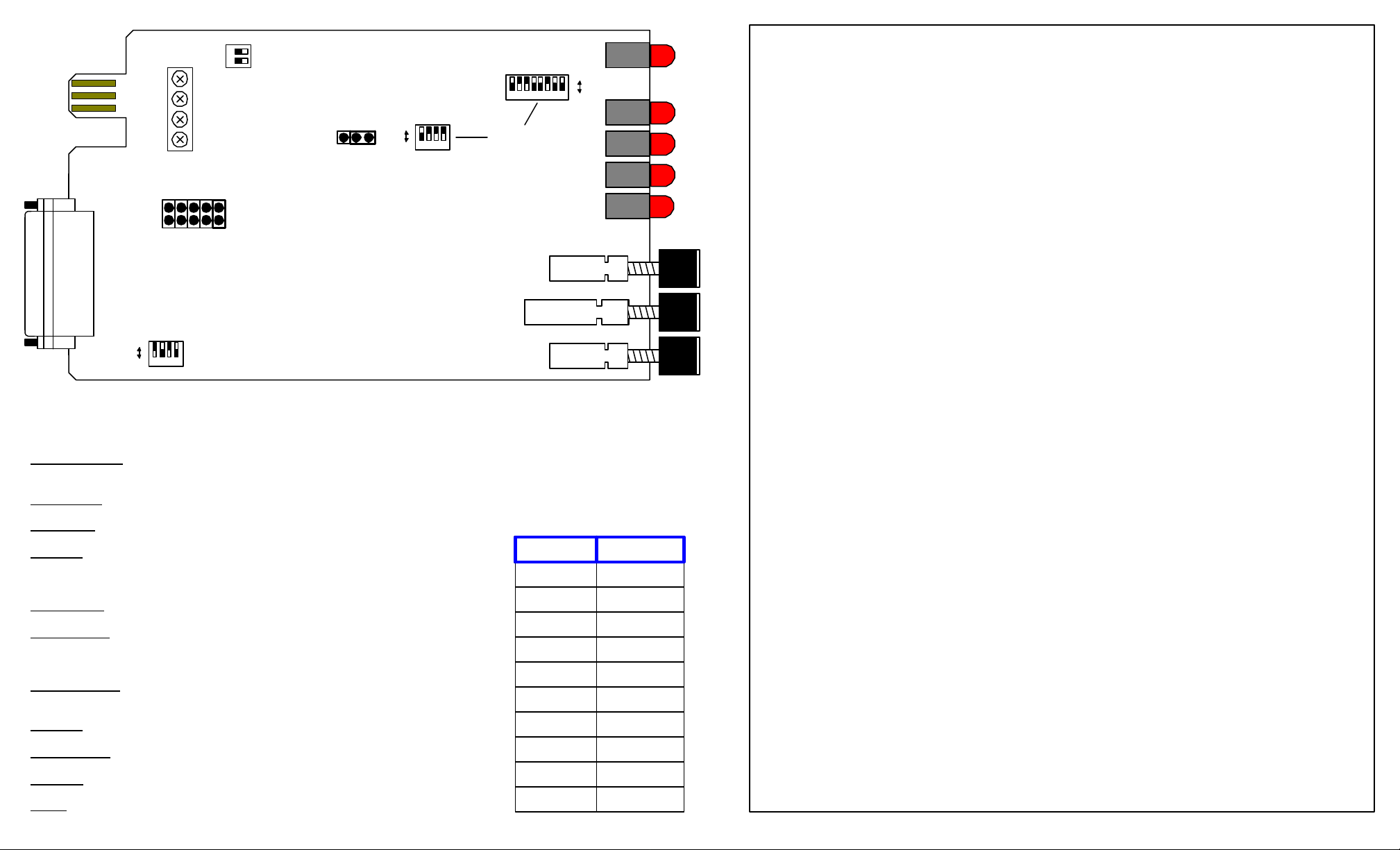
Configuring Your Unit:
The figure above shows a layout of the printed circuit board and the location of the jumpers and switches.
Switches:
Three options are user-configurable via the internal switches:
1. Baud Rate
2. Transmit Data Clock
3. Node Termination
Baud Rate:
Ten switch-selectable data rates are available: 1200, 2400, 4800, 9600 (factory setting), 19200, 38400, 56000, 64000,
112000, or 128000 bps.
The maximum transmission distance is dependent on the data rate selected. The typical range for data transmission is 4
miles at 1200 bps and .35 miles at 12000 bps. Refer to the table to the left for baud rates and maximum transmission
distances.
Note:
The baud rate should be set to match
the rate of the attached DTE.
Transmit Data Clock:
Data timing is synchronized among all connected devices in one of three ways:
1. Internal Clock (factory setting)
2. Recovered Clock
3. External Clock
Internal Clock- Line Driver generates transmit data clock and presents clock to attached DTE via
Pin 15. The DTE then presents synchronized data to the Line Driver on Pin2.
Recovered Clock- Transmit data clock is presented to the DTE on Pin 15, synchronized with timing of
data received from the remote device. The DTE then presents synchronized data
to the Line Driver on Pin 2.
External Clock- Clocking is determined by local DTE. The clock is presented to the Line Driver on
Pin 24, and returned to Pin 15. The DTE then presents synchronized data to the Line
Driver on Pin 2.
Page 2
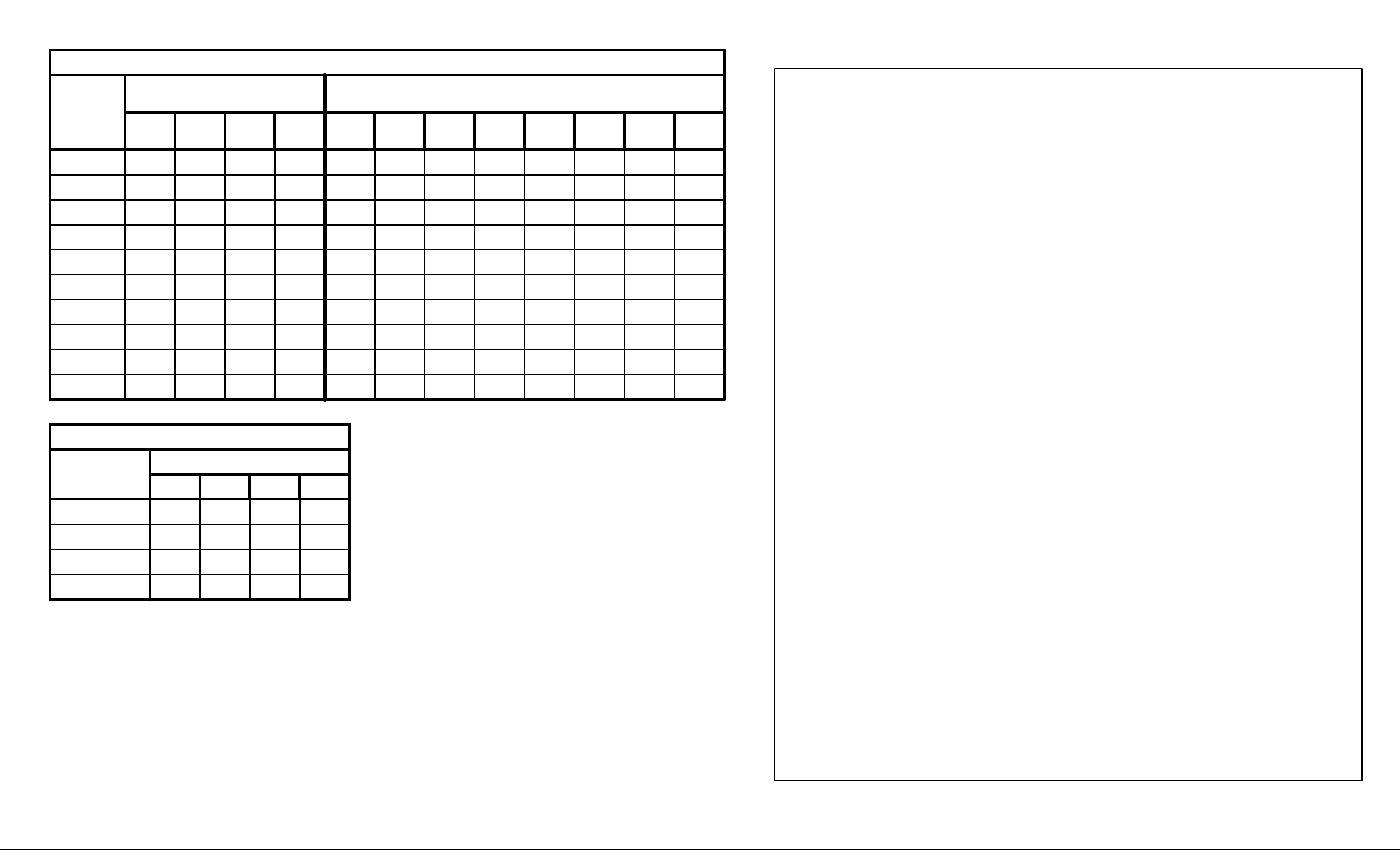
BAUD RATE SETTINGS (SWITCHES 4 AND 5)
BAUD
Switch 4, Position
RATE
(bps)
1200
2400
4800
9600
19200
38400
56000
64000
112000
128000
TRANSMIT CLOCK OPTIONS (Switch 6)
Pin 15
Clock Source
Internal
Recovered
External
Pin 15
Disabled
1 2 3 4
ON
ON
ON
OFF OFF ON
ON ON OFF
ON OFF OFF
ON OFF OFF OFF
OFF OFF OFF OFF
OFF OFF OFF OFF
OFF OFF OFF OFF
OFF OFF OFF OFF
OFF OFF OFF OFF
OFF OFF OFF OFF
Switch 6, Position
1 2 3 4
OFF ON OFF ON
ON OFF OFF ON
OFF OFF ON ON
OFF
- - -
Switch 5, Position
1 2 3 4 5 6 7 8
ON OFF ON ON ON ON ON ON
ON OFF OFF ON ON OFF ON ON
ON OFF OFF ON ON OFF ON ON
ON OFF OFF ON ON OFF ON ON
ON OFF OFF ON ON OFF ON ON
OFF OFF ON OFF ON OFF ON ON
OFF ON OFF OFF ON ON ON ON
OFF ON OFF OFF ON OFF ON ON
ON OFF OFF OFF ON ON OFF ON
OFF ON OFF OFF OFF ON ON OFF
To achieve a Master Clock, one of the Line
Drivers should be set to internal or external
clocking and the other Line Driver(s) set to
recovered clock.
The user can select whether or not the termination network for the receiver is connected to the line.
Node Termination:
Terminating the devices on the extreme ends of the line reduces distortion and improves overall signal quality in
most applications. The factory setting is with Switch 7 in the TERM position.
In Point-to-Point applications, both devices should have the node termination option enabled.
In multipoint applications, only the two devices at the extreme ends of the line should be terminated. Configuring
any of the other devices on the line for node termination would result in an increase in the amount of distortion and
possible data errors.
Jumpers:
Four options are user-configurable via internal jumpers:
1. Constant Carrier/Switched Mode-Jumper W2
2. RTS/CTS Delay (for Switched Mode)-Jumper W2
3. Full/Half Duplex-Jumper W3
4. Frame Ground/Signal Ground-Jumper W1
Constant Carrier or Switched Mode:
Jumper W2 is used to select Constant Carrier or Switched Mode. This option determines the use of the
Request to Send signal, with selection dependent on your particular application. When the jumper block is in the
Constant Carrier position, Constant Carrier Mode is selected. If Switched Mode is desired, the jumper block would
be placed in one of the four RTS/CTS delay positions.
In Constant Carrier Mode, the unit functions as if RTS is constantly asserted. The EIA 485 transmitter is
always on, and the unit CTS signal remains high. Any data sent by the attached RS-232 device is automatically
transmitted by the Line Driver. The RTS LED on the unit's front panel will always be on, and the CD indicator of the
remote Line Driver(s) will remain lit. Constant Carrier Mode is most commonly used in multipoint applications that
have a "master" device communicating with two or more "slaves". The master DTE is configured for Constant
Carrier Mode, while the slave devices are set to Switched Mode.
NOTE:
Constant Carrier Mode pertains to full duplex or simplex
operation only. Half duplex does not apply since the RTS
signal is constantly held high in this mode, preventing any
other signals from being raised in the sequential fashion
required by half duplex operation.
In Switched Mode, the Line Driver's transmitter isn't activated until the DTE device asserts RTS. (Unlike
Constant Carrier Mode, RTS is not held in a pseudo-asserted state). When the attached DTE device raises RTS,
the Line Driver's RTS LED will light. The remote unit's CD LED will light, indicating that a transmission link has
been established. Once the device drops RTS, the RTS and remote CD lights will go out.
RTS/CTS Delay:
If desired, the user can have a delay inserted after the RS-232 device raises RTS. It will delay the return of
CTS from the Line Driver to the DTE. This feature is useful in applications that require time for the remote driver's
Carrier Detect (CD) signal to activate the link between both RS-232 devices before CTS is raised. If CD hasn't
been asserted before CTS, the link is considered inactive and data transmission should not be attempted by the
attached DTE.
In half duplex operation, the RTS/CTS delay is useful because it allows time to establish which Line Driver will
have control of the line to transmit data
NOTE:
RTS/CTS delay applies to Switched Mode ONLY.
This jumper allows you to select 2- or 4-wire operation. The factory setting is full duplex.
Full or Half-Duplex Operation:
Page 3

4-WIRE POINT-TO-POINT APPLICATION
TXA
TXB
RXA
RXB TXA
RXB
RXA
TXB
4-WIRE POINT-TO-MULITPOINT APPLICATION
TXA
TXB
MASTER SLAVE
RXA
RXB TXA
RXB
RXA
TXB
RXB
RXA
TXB
TXA
SLAVE
Page 4

2-WIRE POINT-TO-POINT APPLICATION
TXA
TXB
RXA
RXB TXA
RXB
RXA
TXB
2-WIRE POINT-TO-MULITPOINT APPLICATION
TXA
TXB
MASTER SLAVE
RXA
RXB TXA
RXB
RXA
TXB
RXB
RXA
TXB
TXA
SLAVE
 Loading...