

Page 1
OCTOBER 1998
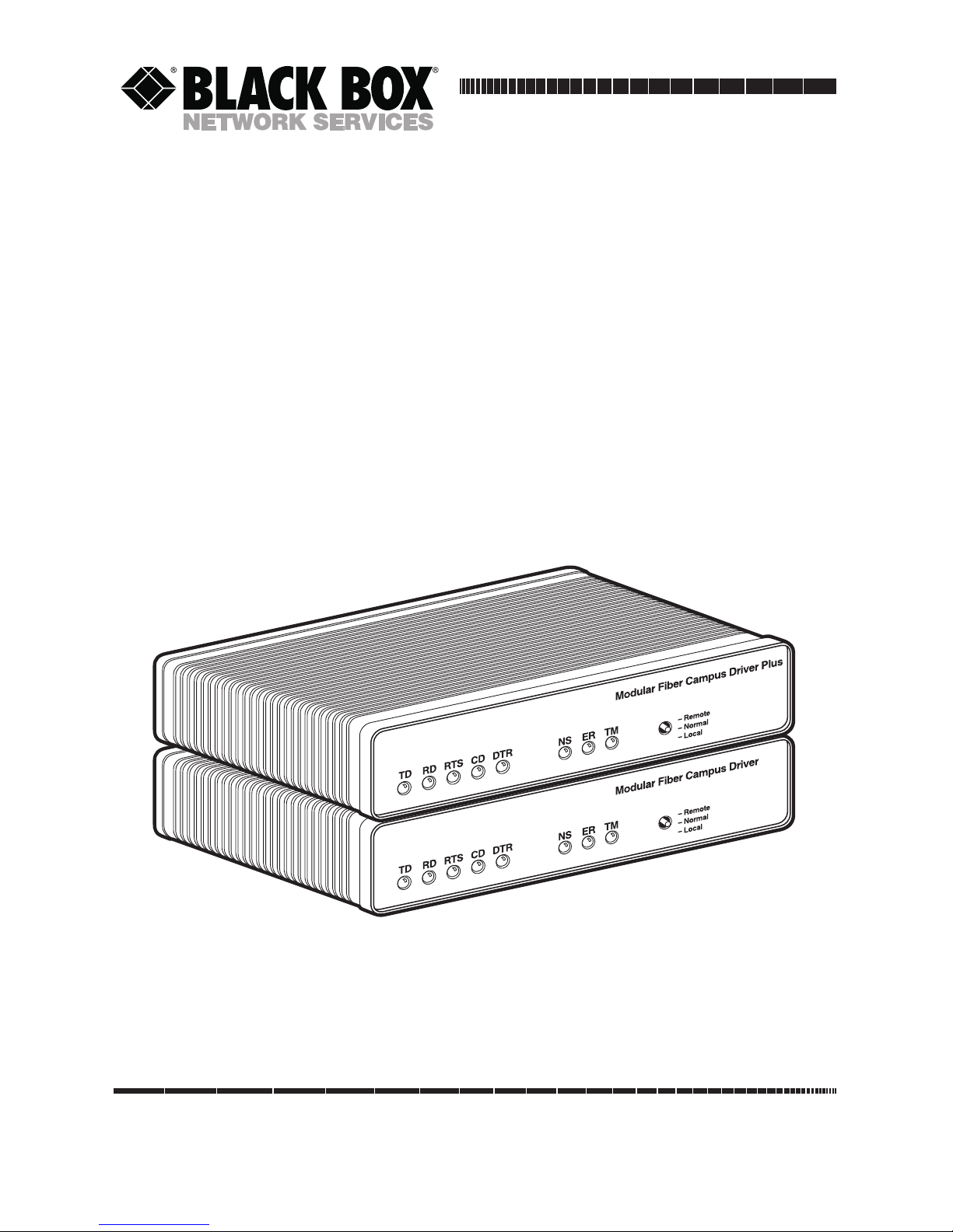
ME620A
ME621A
Modular Fiber Campus Driver Plus-
256 kbps
Modular Fiber Campus Driver-128 kbps
CUSTOMER
SUPPORT
INFORMATION
Order toll-free in the U.S.: Call 877-877-BBOX (outside U.S. call 724-746-5500)
FREE technical support 24 hours a day, 7 days a week: Call 724-746-5500 or fax 724-746-0746
Mailing address: Black Box Corporation, 1000 Park Drive, Lawrence, PA 15055-1018
Web site: www.blackbox.com • E-mail: info@blackbox.com
Page 2

1
MODULAR FIBER CAMPUS DRIVER, MFCD PLUS
FEDERAL COMMUNICATIONS COMMISSION
AND
CANADIAN DEPARTMENT OF COMMUNICATIONS
RADIO FREQUENCY INTERFERENCE STATEMENTS
This equipment generates, uses, and can radiate radio frequency energy and if not
installed and used properly, that is, in strict accordance with the manufacturer’s
instructions, may cause interference to radio communication. It has been tested
and found to comply with the limits for a Class A computing device in accordance
with the specifications in Subpart B of Part 15 of FCC rules, which are designed to
provide reasonable protection against such interference when the equipment is
operated in a commercial environment. Operation of this equipment in a
residential area is likely to cause interference, in which case the user at his own
expense will be required to take whatever measures may be necessary to correct the
interference.
Changes or modifications not expressly approved by the party responsible for
compliance could void the user’s authority to operate the equipment.
This digital apparatus does not exceed the Class A limits for radio noise emission from digital
apparatus set out in the Radio Interference Regulation of the Canadian Department of
Communications.
Le présent appareil numérique n’émet pas de bruits radioélectriques dépassant les limites
applicables aux appareils numériques de la classe A prescrites dans le Règlement sur le
brouillage radioélectrique publié par le ministère des Communications du Canada.
The CE symbol on your equipment indicates that it complies with the
Electromagnetic Compatibility (EMC) directive and the Low Voltage Directive
(LVD) of the Union European (EU).
Page 3

2
MODULAR FIBER CAMPUS DRIVER, MFCD PLUS
NORMAS OFICIALES MEXICANAS (NOM)
ELECTRICAL SAFETY STATEMENT
INSTRUCCIONES DE SEGURIDAD
1. Todas las instrucciones de seguridad y operación deberán ser leídas antes de
que el aparato eléctrico sea operado.
2. Las instrucciones de seguridad y operación deberán ser guardadas para
referencia futura.
3. Todas las advertencias en el aparato eléctrico y en sus instrucciones de
operación deben ser respetadas.
4. Todas las instrucciones de operación y uso deben ser seguidas.
5. El aparato eléctrico no deberá ser usado cerca del agua—por ejemplo, cerca
de la tina de baño, lavabo, sótano mojado o cerca de una alberca, etc..
6. El aparato eléctrico debe ser usado únicamente con carritos o pedestales que
sean recomendados por el fabricante.
7. El aparato eléctrico debe ser montado a la pared o al techo sólo como sea
recomendado por el fabricante.
8. Servicio—El usuario no debe intentar dar servicio al equipo eléctrico más allá
a lo descrito en las instrucciones de operación. Todo otro servicio deberá ser
referido a personal de servicio calificado.
9. El aparato eléctrico debe ser situado de tal manera que su posición no
interfiera su uso. La colocación del aparato eléctrico sobre una cama, sofá,
alfombra o superficie similar puede bloquea la ventilación, no se debe colocar
en libreros o gabinetes que impidan el flujo de aire por los orificios de
ventilación.
10. El equipo eléctrico deber ser situado fuera del alcance de fuentes de calor
como radiadores, registros de calor, estufas u otros aparatos (incluyendo
amplificadores) que producen calor.
11. El aparato eléctrico deberá ser connectado a una fuente de poder sólo del
tipo descrito en el instructivo de operación, o como se indique en el aparato.
Page 4

3
MODULAR FIBER CAMPUS DRIVER, MFCD PLUS
12. Precaución debe ser tomada de tal manera que la tierra fisica y la polarización
del equipo no sea eliminada.
13. Los cables de la fuente de poder deben ser guiados de tal manera que no
sean pisados ni pellizcados por objetos colocados sobre o contra ellos,
poniendo particular atención a los contactos y receptáculos donde salen del
aparato.
14. El equipo eléctrico debe ser limpiado únicamente de acuerdo a las
recomendaciones del fabricante.
15. En caso de existir, una antena externa deberá ser localizada lejos de las lineas
de energia.
16. El cable de corriente deberá ser desconectado del cuando el equipo no sea
usado por un largo periodo de tiempo.
17. Cuidado debe ser tomado de tal manera que objectos liquidos no sean
derramados sobre la cubierta u orificios de ventilación.
18. Servicio por personal calificado deberá ser provisto cuando:
A: El cable de poder o el contacto ha sido dañado; u
B: Objectos han caído o líquido ha sido derramado dentro del aparato; o
C: El aparato ha sido expuesto a la lluvia; o
D: El aparato parece no operar normalmente o muestra un cambio en su
desempeño; o
E: El aparato ha sido tirado o su cubierta ha sido dañada.
Page 5

4
MODULAR FIBER CAMPUS DRIVER, MFCD PLUS
TRADEMARKS
The trademarks mentioned in this manual are the sole property of their owners.
Page 6

5
MODULAR FIBER CAMPUS DRIVER, MFCD PLUS
Contents
Chapter Page
1. Specifications . . . . . . . . . . . . . . . . . . . . . . . . . . . . . . . . . . . . . . . . . . . . . . . . . . . . 6
2. Introduction . . . . . . . . . . . . . . . . . . . . . . . . . . . . . . . . . . . . . . . . . . . . . . . . . . . . . 7
2.1 General Product Description . . . . . . . . . . . . . . . . . . . . . . . . . . . . . . . . . . . . . 7
2.2 Features . . . . . . . . . . . . . . . . . . . . . . . . . . . . . . . . . . . . . . . . . . . . . . . . . . . . . . 7
3. Configuration . . . . . . . . . . . . . . . . . . . . . . . . . . . . . . . . . . . . . . . . . . . . . . . . . . . . 9
Configuration Switch S1. . . . . . . . . . . . . . . . . . . . . . . . . . . . . . . . . . . . . . . . . . . . 9
4. Installation. . . . . . . . . . . . . . . . . . . . . . . . . . . . . . . . . . . . . . . . . . . . . . . . . . . . . . . 13
4.1 Connection to the Fiber Interface. . . . . . . . . . . . . . . . . . . . . . . . . . . . . . . . . 13
4.2 Connection to the Serial Port . . . . . . . . . . . . . . . . . . . . . . . . . . . . . . . . . . . . 14
4.2.1 Changing Modules. . . . . . . . . . . . . . . . . . . . . . . . . . . . . . . . . . . . . . . . . . 14
4.2.2 Connection to a “DTE” Device . . . . . . . . . . . . . . . . . . . . . . . . . . . . . . . . 15
4.2.3 Connection to a “DCE” Device . . . . . . . . . . . . . . . . . . . . . . . . . . . . . . . . 15
4.2.4 Re-configuring the X.21 Module . . . . . . . . . . . . . . . . . . . . . . . . . . . . . . 16
4.3 Power Connection . . . . . . . . . . . . . . . . . . . . . . . . . . . . . . . . . . . . . . . . . . . . . 16
5. Operation . . . . . . . . . . . . . . . . . . . . . . . . . . . . . . . . . . . . . . . . . . . . . . . . . . . . . . . 17
5.1 Power-On . . . . . . . . . . . . . . . . . . . . . . . . . . . . . . . . . . . . . . . . . . . . . . . . . . . . . 17
5.2 LED Status Monitors. . . . . . . . . . . . . . . . . . . . . . . . . . . . . . . . . . . . . . . . . . . . 17
5.3 Diagnostics. . . . . . . . . . . . . . . . . . . . . . . . . . . . . . . . . . . . . . . . . . . . . . . . . . . . 18
5.3.1 Local Analog Loopback. . . . . . . . . . . . . . . . . . . . . . . . . . . . . . . . . . . . . . 18
5.3.2 Remote Analog Loopback. . . . . . . . . . . . . . . . . . . . . . . . . . . . . . . . . . . . 19
Appendix: Interface Pin Assignments. . . . . . . . . . . . . . . . . . . . . . . . . . . . . . . . . . . 21
Page 7

6
MODULAR FIBER CAMPUS DRIVER, MFCD PLUS
1. Specifications
Transmission—Asynchronous and synchronous
Clocking—Internal, external or derived from receive signal
Distance—Up to 3 miles (4.8 km)
ME621A Data Rates—Asynchronous: 0 to 19.2 kbps; Synchronous: 4.8, 9.6, 14.4,
19.2, 28.8, 32.0, 56.0, 64.0, 128.0 kbps
ME620A Data Rates—Asynchronous: 2.4 to 38.4 kbps; Synchronous: 2.4, 9.6,
14.4, 28.8, 38.4, 56.0, 64.0, 72.0, 128.0, 144.0, 192.0, 256.0 kbps
Handshaking—Software (XON/XOFF) or hardware (RTS/CTS); both modes
available at all time.
Connectors—(1) Fiber ST
Link Budget—12 dB (62.5 micron), 8 dB (50.0 micron)
Diagnostics—V.54 Compliant; Local Analog Loopback and Remote Digital
Loopback bit-error-rate pattern
Fiber Modes—Single 50- or 62.5-micron core, multi-mode fiberoptic cable
LED Indicators—TD, RD, RTS, DTR, ER, NS and TM
Interface Modules—EIA RS-232/CCITT V.24, RS-232/530, CCITT V.35, X.21,
Ethernet Bridge and G.703
Power—85 to 256 VAC universal-input power supply, 50/60 Hz
Regulatory Compliance—FCC part 15 Class A, UL 1950, EN60950 89/336/EEC,
73/23/EEC IEC 825 Class 1 equipment
Temperature Range—32 to 122°F (0 to 50°C)
Altitude—Up to 15,000 feet (4572 m)
Humidity—5 to 95% non-condensing
Size—1.6"H x 7.3"W x 6.6"D (4.1 x 18.5 x 16.8 cm)
Weight—2.02 lb. (1 kg)
Page 8

7
MODULAR FIBER CAMPUS DRIVER, MFCD PLUS
2. Introduction
2.1 Description
The Modular Fiber Campus Driver (ME621A) and the Modular Fiber Campus
Driver Plus (ME620A) are designed for high-speed RS-232 communication over a
single multi-mode fiber. Operating at up to 128 kbps synchronous and 19.2 kbps
asynchronous data rates, the ME621A is perfect for campus applications where
data integrity is a must. The ME620A is even faster at a bursty 256 kbps
synchronous or 38.4 kbps async. Synchronous clocking options include internal,
external, or receive recovered clock.
Both models feature swappable DCE-DTE interface modules. Available
interfaces include V.24/RS-232 (part number ME481C-232), V.35 (part number
ME481C-35), RS-422/530 (part number ME481C-422), X.21 (part number
ME481C-X21), WAN Bridge (part number ME530A), and G.703 (part number
ME481C-G703). Fiber connections are made using an ST interface.
The Campus Drivers also incorporate V.54 compliant local and remote
loopback test modes that are activated by a convenient front panel switch. LED
status indicators monitor interface data and control signals as well as test mode
status. Available with a universal AC power supply, the Campus Drivers
conveniently fit in a wide range of applications and power supply environments.
If any questions or problems arise during installation or use of the Modular
Fiber Campus Drivers, please call Black Box Technical Support at 724-746-5500.
2.2 Features
• ME621A: Synchronous data rates: 4.8 to 128 kbps; Asynchronous data rates:
0 to 19.2 kbps
• ME620A: Synchronous data rates: 2.4 to 256 kbps; Asynchronous data rates:
0 to 38.4 kbps
• Full-duplex operation over a single multi-mode fiberoptic cable
• Point-to-point distances up to 3 miles (4.8 km)
• Internal, external or receive recovered clocking options
• Field-replaceable DTE-DCE interface modules: V.24/RS-232, V.35,
RS-422/530, X.21 and G.703 (modules ordered separately)
Page 9

8
MODULAR FIBER CAMPUS DRIVER, MFCD PLUS
• V.54-compliant local and remote digital loopback tests
• 8 front-panel LED status indicators
• Available with ST fiber connectors
• Made in the U.S.A.
Page 10

9
MODULAR FIBER CAMPUS DRIVER, MFCD PLUS
3. Configuration
Both Models ME621A and ME620A use a mini DIP-switch package that allows
configuration to a wide range of applications. These switches are located on the
bottom side of the PC board (see Figure 3-1). Because all eight switches are
externally accessible, you don’t have to open the case to configure the unit.
Figure 3-1. Underside of the Campus Driver, showing the location of the
DIP switches.
Configuration Switch “S1”
The switches shown in Figure 3-2 and on DIP switch S1 are used to set the async or
sync data rates, LAL and DL diagnostic functions, and the clock-mode setting. The
default settings for DIP switch S1 are shown in Table 3-1. Following the table are
detailed descriptions for each switch.
Figure 3-2. Close-up of configuration switches.
Page 11

10
MODULAR FIBER CAMPUS DRIVER, MFCD PLUS
Table 3-1. S1 Summary Table.
Position Function Factory Default
S1-1* Data Rate Off
S1-2* Data Rate Off
S1-3* Data Rate Off
S1-4* Data Rate On
S1-5 Clock Source On
S1-6 Clock Source On
S1-7 DTE Control of DL Off Disabled
S1-8 DTE Control of LAL Off Disabled
*NOTE
Both models ME621A and ME620A use Switches S1-S4 to set the async
or sync data rate. Refer to the sections below to set the ME621A or
ME620A rates.
S
WITCH
S1-1
THROUGH
S1-4 (M
ODEL
ME621A:): A
SYNC/SYNCDATARATE
On ME621A, Switches S1-1, S1-2, S1-3 and S1-4 set two parameters: synchronous or
asynchronous data rate and the maximum transmission distance between two
Model ME621As.
Data Max. Distance
S1-1 S1-2 S1-3 S1-4 Rate (kbps) in miles (km)
On Off Off On 0-19.2 3.0 (4.8) Async Setting
Off On On Off 4.8 3.0 (4.8)
Off On On On 9.6 3.0 (4.8)
On Off On Off 14.4 1.5 (2.4)
On Off On On 19.2 3.0 (4.8)
Off Off On Off 28.8 1.5 (2.4)
Off Off Off Off 32.0 3.0 (4.8)
Off On Off Off 56.0 1.5 (2.4)
Off Off Off On 64.0 3.0 (4.8)
On On On On 128.0 3.0 (4.8)
}
64 kbps
}
Internal
}
Sync
Setting
Page 12

11
MODULAR FIBER CAMPUS DRIVER, MFCD PLUS
S
WITCH
S1-1
THROUGH
S1-4 (M
ODEL
ME620A): A
SYNC/SYNCDATARATE
On Model ME620A, Switches S1-1, S1-2, S1-3 and S1-4 set two parameters:
synchronous or asynchronous data rate and the maximum transmission distance
between two Model ME620As.
Data Max Distance
S1-1 S1-2 S1-3 S1-4 Rate (kbps) in miles (km)
On Off Off On 0-19.2 3.0 (4.8) Async Settings
On Off Off Off 0-38.4 1.5 (2.4)
On On On Off 2.4 1.5 (2.4)
Off On On On 9.6 3.0 (4.8)
On Off On Off 14.4 1.5 (2.4)
On Off On On 19.2 3.0 (4.8)
Off Off On Off 28.8 1.5 (2.4)
Off Off On On 38.4 3.0 (4.8)
On On Off On 48.0 3.0 (4.8)
Off On Off Off 56.0 1.5 (2.4)
Off Off Off On 64.0 3.0 (4.8)
Off On On Off 72.0 1.5 (2.4)
Off Off Off Off 128.0 1.5 (4.8)
On On Off Off 144.0 1.5 (2.4)
Off On Off On 192.0 1.5 (2.4)
On On On On 256.0 1.5 (2.4)
S
WITCHES
S1-5
AND
S1-6: C
LOCKSOURCE
Switches S1-5 and S1-6 are set in combination to determine the transmit clock
source for both models.
S1-5 S1-6 Setting Description
On Off Internal Transmit clock generated internally
On On Internal Transmit clock generated internally
Off On External Transmit clock derived from terminal
interface
Off Off Received Recover Transmit clock derived from the
received line signal
}
Sync
Setting
Page 13

12
MODULAR FIBER CAMPUS DRIVER, MFCD PLUS
NOTE
Because communication between two Model ME620As is always
synchronous, you must set these switches whether your application is
async or sync. For X.21 or async applications, configure one unit for
internal clock mode and the other for receive recover clock mode.
S
WITCH
S1-7: DTE C
ONTROL OF
DL
The setting for Switch S1-7 determines whether DTE control of remote digital
loopback test is enabled or disabled. If DTE control is disabled, the DL test can
only be initiated by the front-panel switch. If DTE control is not available, set
switch S1-7 to the Off position.
S1-7 Setting Description
On Enabled Respond to DL requests from DTE
Off Disabled Ignore DL requests from the DTE
S
WITCH
S1-8: DTE C
ONTROL OF
LAL
The setting for switch S1-8 determines whether DTE control of local analog
loopback test is enabled or disabled. If DTE control is disabled, the LAL test can
only be initiated by the front-panel switch. If DTE control is not available, set
switch S1-8 to the Off position.
S1-7 Setting Description
On Enabled Respond to LAL requests from DTE
Off Disabled Ignore LAL requests from the DTE
Page 14

13
MODULAR FIBER CAMPUS DRIVER, MFCD PLUS
4. Installation
Once the ME621A or ME620A is properly configured, it is ready to connect to the
fiber interface, to the serial port, and to the power source. This section tells you
how to make these connections.
4.1 Connection to the Fiber Interface
The ME621A supports communication at distances to 3 miles (4.8 km) and data
rates to 128 kbps (sync) or 19.2 kbps (async). The ME620A also supports distances
up to 3 miles (4.8 km), but at rates up to 256 kbps (sync) or 38.4 kbps (async).
Figure 4-1 shows the position of the interface connectors on the ME621A or
ME620A back panel.
Figure 4-1. Rear panel of Campus Driver, showing interface and power
connectors.
These short range modems are designed to work in pairs. You will need one at
each end of single 50- or 62.5-micron multi-mode fiber cable. The fiber cable
connects to each ME621A or ME620A using an ST connector. Figure 4-2 below
shows a close-up of the ST connector.
Figure 4-2. Close-up of the ST connector.
Page 15

14
MODULAR FIBER CAMPUS DRIVER, MFCD PLUS
4.2 Connection to the Serial Port
The serial port interface on the Campus Driver uses interchangeable modules.
Each module has a 50-pin card-edge connector on one side and a serial port on
the other. Figure 4-3 below shows how a Module plugs into the back of the Campus
Driver.
Figure 4-3. Installing a plug-in serial interface module.
4.2.1 C
HANGINGMODULES
When you purchase a particular version of the ME621A or ME620A, it should be
shipped to you without any modules installed. The modules mentioned on page 7
are ordered separately. If you need to install one of these Modules, follow these
steps:
Removing an Existing Module
1. Turn the power switch off. Leave the power cord plugged into a grounded
outlet to keep the unit grounded.
2. Loosen the two thumbscrews on the module by turning them
counterclockwise.
3. Grasp the two thumbscrews and gently pull the module from the unit. Apply
equal force to the thumbscrews to keep the module straight during the
removal process.
Installing the New Module
1. Make sure the power switch is off. Leave the power cord plugged into a
grounded outlet to keep the unit grounded.
Page 16

15
MODULAR FIBER CAMPUS DRIVER, MFCD PLUS
2. Hold the module with the faceplate toward you and align the module with
the guide slots in the rear panel of the Campus Driver.
3. While keeping the module’s faceplate parallel with the Campus Driver rear
panel, slide the module straight in, so that the card-edge contacts line up with
the socket inside the chassis.
NOTE
The card-edge connector should meet the socket when the Module is
almost all the way into the chassis. If you encounter a lot of resistance,
remove the module and repeat steps 2 & 3.
4. With the card-edge contacts aligned with the socket, firmly seat the module by
using your thumbs to apply pressure directly to the right and left edges of the
module faceplate. Applying moderate and even pressure should be sufficient
to seat the module. You should hear it “click” into place.
5. To secure the module in place, push the thumbscrews into the chassis and
turn the screws clockwise to tighten.
4.2.2 C
ONNECTION TO A
“DTE” D
EVICE
The serial port on most interface modules (all except the X.21 module) is hardwired as DCE. Therefore these modules “want” to plug into a DTE such as a
terminal, PC, or host. When making the connection to your DTE device, use a
straight-through cable of the shortest possible length—we recommend 6 feet
(1.8 m) or less. When purchasing or constructing an interface cable, please refer
to the pin diagrams in the Appendix as a guide.
4.2.3 C
ONNECTION TO A
“DCE” D
EVICE
The serial port on most interface modules is hard-wired as a DCE (all except the
X.21 module). Therefore you must use a null-modem cable when connecting to a
modem, multiplexor, or other DCE device. This cable should be of the shortest
possible length—we recommend 6 feet (1.8 m) or less. When purchasing or
constructing a null-modem cable, use the pin diagrams in the Appendix as a guide.
NOTE
Pin-out requirements for null-modem applications vary widely between
manufacturers. If you have any questions about a specific application,
contact Black Box Technical Support at 724-746-5500.
Page 17

16
MODULAR FIBER CAMPUS DRIVER, MFCD PLUS
4.2.4 R
E
-
CONFIGURING THE
X.21 M
ODULE
The serial port on the X.21 Module is wired by default as a DCE, but may be
switched to a DTE. This is done by reversing the orientation of the DCE/DTE
strap.
To reverse DCE/DTE orientation, remove the module according to the
instructions in Section 4.2.1. The DCE/DTE strap is located on the bottom side of
the module’s PC board. The arrows on the top of the strap indicate the
configuration of the X.21 port (for example, if the DCE arrows are pointing
toward the DB15 connector, the X.21 port is wired as a DCE). Reverse the
DCE/DTE orientation by pulling the strap out of its socket, rotating it 180°, then
plugging the strap back into the socket. You will see that the DCE/DTE arrows
now point in the opposite directions, showing the new configuration of the X.21
port. Reinstall the module according to the instructions in Section 4.2.1.
4.3 Power Connection
The Fiber Campus Driver comes with a universal-interface AC power supply, which
operates in environments ranging from 85 to 256 VAC, with no re-configuration
necessary.
C
ONNECTING TO AN
AC P
OWERSOURCE
The universal AC power supply is equipped with a male IEC-320 power
connection. A domestic (US) power supply cord is supplied with the unit at no
extra charge. To connect the universal power supply, follow these steps:
1. Attach the power cord (supplied) to the shrouded male IEC-320 connector
on the rear of the Campus Driver.
2. Plug the power cord into a nearby AC power outlet.
3. Turn the rear power switch ON.
Page 18

17
MODULAR FIBER CAMPUS DRIVER, MFCD PLUS
5. Operation
Once the Campus Driver is properly configured and installed, it should operate
transparently. This section describes power-up, reading the LED status monitors,
and using the built-in loopback tests.
5.1 Power-Up
To apply power to the Campus Driver, first be sure that you have read Section 4.3,
and that the unit is connected to the appropriate power source. Then power up
the unit using the rear power switch.
5.2 LED Status Monitors
The Campus Drivers feature eight front-panel LEDs that monitor power, the DTE
signals, network connection, and test modes. Figure 5-1 shows the front-panel
location of each LED. Following Figure 5-1 is a description of each LED’s function.
Figure 5-1. ME620A front panel.
TD & RD: Glows red to indicate an idle condition of Binary “1” data on the
respective terminal interface signals. Green indicates Binary “0” data.
RTS: Glows green to indicate that the Request to Send signal from the DTE is
active.
CD: Glows red if no carrier signal is being received from the remote modem.
Green indicates that the remote modem’s carrier is being received.
DTR: Glows green to indicate that the Data Terminal Ready signal from the
terminal is active.
Page 19

18
MODULAR FIBER CAMPUS DRIVER, MFCD PLUS
ER: Glows red to indicate the likelihood of a Bit Error in the received signal.
During the 511 or 511/E test, ER will flash to indicate that the Test Pattern
Detector has detected a bit error.
TM: Glows red to indicate that the ME620A or ME621A has been placed in Test
Mode. The unit can be placed in test mode by the local or remote user.
NS: Glows red to indicate that the local Campus Driver has not yet connected with
the remote Campus Driver.
5.3 Diagnostics
The Campus Drivers are equipped with V.54 diagnostics that may be used to to
evaluate the condition of the local and remote units, as well as the twisted-pair link
between them: local loopback (LAL) and remote digital loopback (DL).
5.3.1 L
OCALANALOGLOOPBACK
The Local Analog Loopback (LAL) test checks the operation of the local Campus
Driver and is performed separately on each unit. Any data sent to the local Campus
Driver in this test mode will be echoed back (returned) to the user device. (See
Figure 5-2, below). For example, characters typed on the keyboard of a terminal
will appear on the terminal screen.
Figure 5-2. Local analog loopback.
To perform a Local Analog Loopback test, follow these steps.
1. Activate LAL either by moving the front panel toggle switch DOWN to
“Local,” or by raising the appropriate signal on the DTE interface. Once
Local Analog Loopback is activated, the Campus Driver transmit output is
connected to its own receiver. The test LED should glow.
Page 20

19
MODULAR FIBER CAMPUS DRIVER, MFCD PLUS
NOTE
Although the local Campus Driver cannot communicate with the remote
Campus Driver in this mode, the synchronized connection between the
two modems remains intact.
2. Verify that the data terminal equipment is operating properly and can be
used for a test. If a fault is indicated, call a technician or replace the unit.
3. Perform a BER (bit error rate) test on each unit using a separate BER tester.
If the BER test equipment indicates no faults but the data terminal indicates a
fault, follow the manufacturer’s checkout procedures for the data terminal.
Also, check the interface cable between the terminal and the Campus Driver.
5.3.2 R
EMOTEDIGITALLOOPBACK
The Remote Digital Loopback test checks the performance of both the local and
remote Campus Driver, and the communication link between them. Any
characters sent to the remote unit in this test mode will be returned back to the
originating device (see Figure 5-2).
Figure 5-2. Remote digital loop.
To perform an DL test, follow these steps:
1. Activate DL. This may be done in one of two ways: First, by moving the front
panel toggle switch DOWN to “Remote.” Or, second, by raising the DL signal
on the terminal interface (for pin numbers, see the Appendix).
2. Perform a BER (bit error rate) test on the system, using BER testers on both
ends.
Page 21

20
MODULAR FIBER CAMPUS DRIVER, MFCD PLUS
3. If the BER test equipment indicates a fault and the Local Analog Loopback
test was successful for both Campus Drivers, you may have a problem with the
line between the units. You should inspect the line for proper connections.
Page 22

21
MODULAR FIBER CAMPUS DRIVER, MFCD PLUS
Appendix: Interface Pin
Assignments
V.35 Interface Pin Description, M/34 Female Connector
Pin # Signal
B SGND (Signal Ground)
C RTS (Request to Send)
D CTS (Clear to Send)
E DSR (Data Set Ready)
F CD (Carrier Detect)
H DTR (Data Transfer Ready)
L LLB (Local Line Loop)
M TM (Test Mode)
N DL (Remote Digital Loop)
P TD (Transmit Data)
R RD (Receive Data)
S TD/ (Transmit Data-B)
T RD/ (Receive Data-B)
U XTC (External Transmit Clock)
V RC (Receive Timing)
W XTC/ (External Transmit Clock)
X RC/ (Receive Timing)
Y TC (Test Control-A)
AA TC/ (Test Control-B)
Page 23

22
MODULAR FIBER CAMPUS DRIVER, MFCD PLUS
RS-232, RS-530 Interface Pin Description (DB25 Female Connector)
Pin # Signal
1 FG (Frame Ground)
2 TD (Transmit Data)
3 RD (Receive Data)
4 RTS (Request to Send)
5 CTS (Clear to Send)
6 DSR (Data Set Ready)
7 SGND (Signal Ground)
8 CD (Carrier Detect)
9 RC/ (Receive Timing-B)
10 CD/ (Carrier Detect-B)
11 XTC/ (External Transmit Clock)
12 TC/ (Test Control-B)
13 CTS/ (Clear to Send)
14 TD/ (Transmit Data-B)
15 TC (Test Control-A)
16 RD (Receive Data)
17 RC (Receive Timing)
18 LLB (Local Line Loop)
19 RTS/ (Request to Send)
20 DTR (Data Transfer Rate)
21 DL (Remote Digital Loop)
22 DSR/ (Data Set Ready)
23 DTR/ (Data Transfer Rate)
24 XTC (External Transmit Clock)
25 TM (Test Mode)
Page 24

23
MODULAR FIBER CAMPUS DRIVER, MFCD PLUS
X.21 Interface Pin Description (DB15 Female Connector)
Pin # Signal
1 Frame Ground
2 T (Transmit Data-A)
3 C (Control-A)
4 R (Receive Data-A)
5 I (Indication-A)
6 S (Signal Element Timing-A)
7 BT (Byte Timing-A)
8 SGND (Signal Ground)
9 T/ (Transmit Data-B)
10 C/ (Control-B)
11 R/ (Receive Data-B)
12 I/ (Indication-B)
13 S/ (Signal Element Timing-B)
14 BT/ (Byte Timing-B)
Page 25

24
MODULAR FIBER CAMPUS DRIVER, MFCD PLUS
G.703 Interface Pin Assignment (RJ-45 8-Pin Modular)
Pin # Signal
1 RD+ (Receive Data Tip)
2 RD- (Receive Data Ring)
3 Not Used
4 TD- (Transmit Data Ring)
5 TD+ (Transmit Data Tip)
6 Not Used
7 Not Used
8 Not Used
Page 26

1000 Park Drive • Lawrence, PA 15055-1018 • 724-746-5500 • Fax 724-746-0746
© Copyright 1998. Black Box Corporation. All rights reserved.
 Loading...