

Page 1
CUSTOMER
SUPPORT
INFORMATION
Order toll-free in the U.S. 24 hours, 7 A.M. Monday to midnight Friday: 877-877-BBOX
FREE technical support, 24 hours a day, 7 days a week: Call 724-746-5500 or fax 724-746-0746
Mail order: Black Box Corporation, 1000 Park Drive, Lawrence, PA 15055-1018
Web site: www.blackbox.com • E-mail: info@blackbox.com
JUNE 2000
ME555A
ME555AE
ME556A
ME556AE
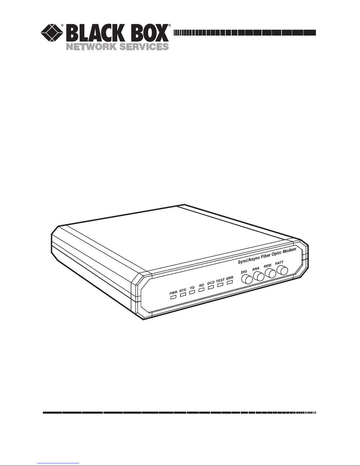
Sync/Async Fiber Optic Modem
Page 2

1
FCC INFORMATION
FEDERAL COMMUNICATIONS COMMISSION
AND
INDUSTRY CANADA
RADIO FREQUENCY INTERFERENCE STATEMENTS
This equipment generates, uses, and can radiate radio frequency energy and if not
installed and used properly, that is, in strict accordance with the manufacturer’s
instructions, may cause interference to radio communication. It has been tested
and found to comply with the limits for a Class A computing device in accordance
with the specifications in Subpart J of Part 15 of FCC rules, which are designed to
provide reasonable protection against such interference when the equipment is
operated in a commercial environment. Operation of this equipment in a
residential area is likely to cause interference, in which case the user at his own
expense will be required to take whatever measures may be necessary to correct the
interference.
Changes or modifications not expressly approved by the party responsible for
compliance could void the user’s authority to operate the equipment.
This digital apparatus does not exceed the Class A limits for radio noise emission from digital
apparatus set out in the Radio Interference Regulation of Industry Canada.
Le présent appareil numérique n’émet pas de bruits radioélectriques dépassant les limites
applicables aux appareils numériques de la classe A prescrites dans le Règlement sur le
brouillage radioélectrique publié par Industrie Canada.
Page 3

2
SYNC/ASYNC FIBER OPTIC MODEM
FCC REQUIREMENTS FOR
TELEPHONE-LINE EQUIPMENT
1. The Federal Communications Commission (FCC) has established rules which
permit this device to be directly connected to the telephone network with
standardized jacks. This equipment should not be used on party lines or coin
lines.
2. If this device is malfunctioning, it may also be causing harm to the telephone
network; this device should be disconnected until the source of the problem
can be determined and until the repair has been made. If this is not done, the
telephone company may temporarily disconnect service.
3. If you have problems with your telephone equipment after installing this
device, disconnect this device from the line to see if it is causing the problem
If it is, contact your supplier or an authorized agent.
4. The telephone company may make changes in its technical operations and
procedures. If any such changes affect the compatibility or use of this device,
the telephone company is required to give adequate notice of the changes.
5. If the telephone company requests information on what equipment is
connected to their lines, inform them of:
a. The telephone number that this unit is connected to.
b. The ringer equivalence number.
c. The USOC jack required: RJ-11C.
d. The FCC registration number.
Items (b) and (d) can be found on the unit’s FCC label. The ringer
equivalence number (REN) is used to determine how many devices can be
connected to your telephone line. In most areas, the sum of the RENs of all
devices on any one line should not exceed five (5). If too many devices are
attached, they may not ring properly.
6. In the event of an equipment malfunction, all repairs should be performed by
your supplier or an authorized agent. It is the responsibility of users requiring
service to report the need for service to the supplier or to an authorized
agent.
Page 4

3
DOC STATEMENT
CERTIFICATION NOTICE FOR
EQUIPMENT USED IN CANADA
The Canadian Department of Communications label identifies certified
equipment. This certification means that the equipment meets certain
telecommunications-network protective, operation, and safety requirements. The
Department does not guarantee the equipment will operate to the user’s
satisfaction.
Before installing this equipment, users should ensure that it is permissible to be
connected to the facilities of the local telecommunications company. The
equipment must also be installed using an acceptable method of connection. In
some cases, the company’s inside wiring associated with a single-line individual
service may be extended by means of a certified connector assembly (extension
cord). The customer should be aware that compliance with the above conditions
may not prevent degradation of service in some situations.
Repairs to certified equipment should be made by an authorized Canadian
maintenance facility—in this case, your supplier. Any repairs or alterations made
by the user to this equipment, or equipment malfunctions, may give the
telecommunications company cause to request the user to disconnect the
equipment.
Users should ensure for their own protection that the electrical ground
connections of the power utility, telephone lines, and internal metallic water pipe
system, if present, are connected together. This precaution may be particularly
important in rural areas.
CONFORMANCE
EN 55022 (1994): Limits and methods of measurement of radio disturbance
characteristics of information technology equipment.
EN 50082-1 (1992): Electromagnetic compatibility—Generic immunity standards
for residential, commercial, and light industry.
Safety: EN 60950 (1992/93): Safety of information technology equipment,
including electrical business equipment.
Page 5

4
SYNC/ASYNC FIBER OPTIC MODEM
TELECOMMUNICATION SAFETY
The safety status of each of the ports on the Sync/Async Fiber Optic Modem is
declared according to EN 41003 and is detailed in the table below:
Safety Status Ports
SELV* RS-530
*SELV=Safety Extra-Low Voltage
LASER WARNINGS
This product may be equipped with a laser diode. The laser warning symbol will be
attached near the optical transmitter. Please observe the following precautions:
• Do not attempt to adjust the laser drive current.
• Do not use broken or unterminated fiber optic cables/connectors or stare at
the laser beam.
• The use of optical equipment with this product will increase eye hazard.
• Use of controls, adjustments, or performing procedures other than those
specified herein, may result in hazardous radiation exposure.
Page 6

5
NOM STATEMENT
NORMAS OFICIALES MEXICANAS (NOM)
ELECTRICAL SAFETY STATEMENT
INSTRUCCIONES DE SEGURIDAD
1. Todas las instrucciones de seguridad y operación deberán ser leídas antes de
que el aparato eléctrico sea operado.
2. Las instrucciones de seguridad y operación deberán ser guardadas para
referencia futura.
3. Todas las advertencias en el aparato eléctrico y en sus instrucciones de
operación deben ser respetadas.
4. Todas las instrucciones de operación y uso deben ser seguidas.
5. El aparato eléctrico no deberá ser usado cerca del agua—por ejemplo, cerca
de la tina de baño, lavabo, sótano mojado o cerca de una alberca, etc..
6. El aparato eléctrico debe ser usado únicamente con carritos o pedestales que
sean recomendados por el fabricante.
7. El aparato eléctrico debe ser montado a la pared o al techo sólo como sea
recomendado por el fabricante.
8. Servicio—El usuario no debe intentar dar servicio al equipo eléctrico más allá
a lo descrito en las instrucciones de operación. Todo otro servicio deberá ser
referido a personal de servicio calificado.
9. El aparato eléctrico debe ser situado de tal manera que su posición no
interfiera su uso. La colocación del aparato eléctrico sobre una cama, sofá,
alfombra o superficie similar puede bloquea la ventilación, no se debe colocar
en libreros o gabinetes que impidan el flujo de aire por los orificios de
ventilación.
10. El equipo eléctrico deber ser situado fuera del alcance de fuentes de calor
como radiadores, registros de calor, estufas u otros aparatos (incluyendo
amplificadores) que producen calor.
11. El aparato eléctrico deberá ser connectado a una fuente de poder sólo del
tipo descrito en el instructivo de operación, o como se indique en el aparato.
Page 7

6
SYNC/ASYNC FIBER OPTIC MODEM
12. Precaución debe ser tomada de tal manera que la tierra fisica y la polarización
del equipo no sea eliminada.
13. Los cables de la fuente de poder deben ser guiados de tal manera que no
sean pisados ni pellizcados por objetos colocados sobre o contra ellos,
poniendo particular atención a los contactos y receptáculos donde salen del
aparato.
14. El equipo eléctrico debe ser limpiado únicamente de acuerdo a las
recomendaciones del fabricante.
15. En caso de existir, una antena externa deberá ser localizada lejos de las lineas
de energia.
16. El cable de corriente deberá ser desconectado del cuando el equipo no sea
usado por un largo periodo de tiempo.
17. Cuidado debe ser tomado de tal manera que objectos liquidos no sean
derramados sobre la cubierta u orificios de ventilación.
18. Servicio por personal calificado deberá ser provisto cuando:
A: El cable de poder o el contacto ha sido dañado; u
B: Objectos han caído o líquido ha sido derramado dentro del aparato; o
C: El aparato ha sido expuesto a la lluvia; o
D: El aparato parece no operar normalmente o muestra un cambio en su
desempeño; o
E: El aparato ha sido tirado o su cubierta ha sido dañada.
Page 8

7
TRADEMARKS
TRADEMARKS USED IN THIS MANUAL
AS/400®is a registered trademark of International Business Machines
Corporation.
ST
®
is a registered trademark of American Telephone and Telegraph Company.
Any other trademarks mentioned in this manual are acknowledged to be the
property of the trademark owners.
Page 9

8
SYNC/ASYNC FIBER OPTIC MODEM
Contents
Quick Start Guide. . . . . . . . . . . . . . . . . . . . . . . . . . . . . . . . . . . . . . . . . . 10
1. Specifications . . . . . . . . . . . . . . . . . . . . . . . . . . . . . . . . . . . . . . . . . . . 12
2. Introduction . . . . . . . . . . . . . . . . . . . . . . . . . . . . . . . . . . . . . . . . . . . . 14
2.1 Overview . . . . . . . . . . . . . . . . . . . . . . . . . . . . . . . . . . . . . . . . . . . . 14
2.1.1 General . . . . . . . . . . . . . . . . . . . . . . . . . . . . . . . . . . . . . . . . . 14
2.1.2 Applications . . . . . . . . . . . . . . . . . . . . . . . . . . . . . . . . . . . . . 14
2.1.3 Versions. . . . . . . . . . . . . . . . . . . . . . . . . . . . . . . . . . . . . . . . . 15
2.1.4 Features. . . . . . . . . . . . . . . . . . . . . . . . . . . . . . . . . . . . . . . . . 15
2.2 Physical Description . . . . . . . . . . . . . . . . . . . . . . . . . . . . . . . . . . . 16
2.2.1 Front Panel . . . . . . . . . . . . . . . . . . . . . . . . . . . . . . . . . . . . . . 16
2.2.2 Rear Panel. . . . . . . . . . . . . . . . . . . . . . . . . . . . . . . . . . . . . . . 16
2.3 Functional Description. . . . . . . . . . . . . . . . . . . . . . . . . . . . . . . . . 16
2.3.1 General . . . . . . . . . . . . . . . . . . . . . . . . . . . . . . . . . . . . . . . . . 16
2.3.2 Interface . . . . . . . . . . . . . . . . . . . . . . . . . . . . . . . . . . . . . . . . 17
2.3.3 Timing. . . . . . . . . . . . . . . . . . . . . . . . . . . . . . . . . . . . . . . . . . 17
2.3.4 Async-to-Sync Converter . . . . . . . . . . . . . . . . . . . . . . . . . . . 17
2.3.5 Diagnostics . . . . . . . . . . . . . . . . . . . . . . . . . . . . . . . . . . . . . . 17
3. Installation and Setup . . . . . . . . . . . . . . . . . . . . . . . . . . . . . . . . . . . . 19
3.1 Introduction . . . . . . . . . . . . . . . . . . . . . . . . . . . . . . . . . . . . . . . . . 19
3.2 Site Requirements and Prerequisites . . . . . . . . . . . . . . . . . . . . . 19
3.2.1 Power. . . . . . . . . . . . . . . . . . . . . . . . . . . . . . . . . . . . . . . . . . . 19
3.2.2 Ambient Requirements . . . . . . . . . . . . . . . . . . . . . . . . . . . . 19
3.3 What the Package Includes . . . . . . . . . . . . . . . . . . . . . . . . . . . . . 20
3.4 What You Need to Supply . . . . . . . . . . . . . . . . . . . . . . . . . . . . . . 20
3.5 Jumper and Switch Settings . . . . . . . . . . . . . . . . . . . . . . . . . . . . . 20
3.5.1 Strap Selection . . . . . . . . . . . . . . . . . . . . . . . . . . . . . . . . . . . 20
3.5.2 Connecting the Interfaces. . . . . . . . . . . . . . . . . . . . . . . . . . 25
3.5.3 Connecting the Power . . . . . . . . . . . . . . . . . . . . . . . . . . . . . 27
4. Operation . . . . . . . . . . . . . . . . . . . . . . . . . . . . . . . . . . . . . . . . . . . . . . 28
4.1 General . . . . . . . . . . . . . . . . . . . . . . . . . . . . . . . . . . . . . . . . . . . . . 28
4.2 Front-Panel Controls and Indicators. . . . . . . . . . . . . . . . . . . . . . 28
4.3 Initial Operation and Basic Checks. . . . . . . . . . . . . . . . . . . . . . . 30
4.3.1 Power-On Procedure . . . . . . . . . . . . . . . . . . . . . . . . . . . . . . 30
4.3.2 Running Self-Test. . . . . . . . . . . . . . . . . . . . . . . . . . . . . . . . . 31
4.4 Operating Instructions . . . . . . . . . . . . . . . . . . . . . . . . . . . . . . . . . 31
4.4.1 Changing Field Strapping . . . . . . . . . . . . . . . . . . . . . . . . . . 31
4.4.2 Running Diagnostic Loops . . . . . . . . . . . . . . . . . . . . . . . . . 32
Page 10

9
CONTENTS
4.4.3 Power-Off Procedure . . . . . . . . . . . . . . . . . . . . . . . . . . . . . . 32
5. Troubleshooting and Diagnostics . . . . . . . . . . . . . . . . . . . . . . . . . . . 33
5.1 General . . . . . . . . . . . . . . . . . . . . . . . . . . . . . . . . . . . . . . . . . . . . . 33
5.2 Loopback Tests . . . . . . . . . . . . . . . . . . . . . . . . . . . . . . . . . . . . . . . 34
5.2.1 Local Test—Local Analog Loopback (LLB)
Standard V.54 . . . . . . . . . . . . . . . . . . . . . . . . . . . . . . . . . . . . 34
5.2.2 Remote Digital Loopback (RLB) Standard V.54. . . . . . . . 35
5.2.3 Local Digital Loopback (DIG) Non-Standard . . . . . . . . . . 36
5.3 Internal BERT Circuit Test . . . . . . . . . . . . . . . . . . . . . . . . . . . . . 37
5.3.1 Modem Self-Test . . . . . . . . . . . . . . . . . . . . . . . . . . . . . . . . . 37
5.3.2 Two-BERT Test. . . . . . . . . . . . . . . . . . . . . . . . . . . . . . . . . . . 38
5.4 (Local) Analog Loopback Test . . . . . . . . . . . . . . . . . . . . . . . . . . 39
5.5 Communication Link Test . . . . . . . . . . . . . . . . . . . . . . . . . . . . . . 41
5.5.1 Remote Digital Loopback . . . . . . . . . . . . . . . . . . . . . . . . . . 41
5.5.2 Local Digital Loopback . . . . . . . . . . . . . . . . . . . . . . . . . . . . 41
Appendix A: DTE Interface Signal Assignments. . . . . . . . . . . . . . . . . 42
Appendix B: Connecting RS-530 to RS-422 . . . . . . . . . . . . . . . . . . . . . 45
Page 11

10
SYNC/ASYNC FIBER OPTIC MODEM
Quick Start Guide
Only an experienced technician should install the Sync/Async Fiber Optic
Modem. If you are familiar with fiberoptic modems, use this Quick Start Guide to
prepare the Modem for operation. If you are not familiar with fiberoptic modems,
please read the entire manual.
Starting up
S
ETTING THEJUMPERS/SWITCHES
Confirm that the following switches and jumpers, mounted on the board, are set
correctly for the chosen operating mode.
WARNING
Make sure that the power cord is disconnected before removing the
unit’s cover.
• Jumper J3: Set the XMT CLOCK mode: INT, EXT, RCV, ASY. Default is INT.
• Selector switch SW3: Set the BAUD RATE: 19.2, 28.8, 32, 38.4, 48, 56, 57.6, 64,
72, 96, 112, 115.2, 128, 144, 192, 256 kbps. Default is 64 kbps.
• Jumper J6: Set SW EN to ON or OFF. Default is ON.
I
NTERFACE ANDCONNECTIONS
• Connect the Data Terminal Equipment to the appropriate DTE connector on
the rear panel of the Fiber Optic Modem.
• Connect the fiber optic cables to the respective Rx-Tx and Tx-Rx connectors
on the rear panel of the Fiber Optic Modem.
C
ONNECTINGPOWERCORD
Fiber Optic Modem, AC Version:
• Power is supplied to the Fiber Optic Modem by a 5-foot (1.5-m) long power
cable, terminated by an appropriate wall plug (see Figure 3-2). Connect the
power cable to the AC input jack on the rear panel of the modem.
Page 12

11
QUICK START GUIDE
C
ONNECTING TOPOWERSOURCE
Connect the Fiber Optic Modem to an AC power source (AC power mains outlet)
or DC source (Ringer). The PWR LED lights to indicate that the Fiber Optic
Modem is on.
V
ERIFYING
P
ERFORMANCE
When data is being transferred, observe that the following front-panel LEDs light
or blink:
• PWR Lights
• RTS Blinks or Not lit
• TD Blinks or Not lit
• RD Lights
• DCD Lights
• TEST Not lit
• ERR Not lit
Testing Performance
V
ERIFYINGMODEMOPERATION
After powering up the modem, if the modem does not operate properly, see
Chapter 4 for more information on Fiber Optic Modem initial functional tests.
Page 13

12
SYNC/ASYNC FIBER OPTIC MODEM
1. Specifications
Electrical Interface
Transmission Rates—Asynchronous: 19.2, 28.8, 38.4, 57.6, and 115.2 kbps;
Synchronous: 19.2, 32, 48, 56, 64, 72, 96, 112, 128, 144, 192, and 256 kbps
Connectors—RS530 via DB25 female
Optical Interface
Operating Wavelength—850 nm for multimode fiber; 1300 nm for single-mode
fiber
Transmission Line—Dual fiber optic cable
Budget (Maximum)—- -18 dBm for 850 nm, 62.5/125 fiber; -18 dBm for
1300 nm; 9/125, 62.5/125 (LED) fiber
Receiver Sensitivity— -48 dBm for 850 nm (LED); -50 dBm for 1300 and
1550 nm (laser diode)
Dynamic Range—36 dB
NOTE
The ranges specified above were calculated according to the following
typical attenuation rates (with a 3-dBm margin):
3.5 dB/km for 850 multimode
0.4 dB/km for 1300 nm single mode
Connectors—ST
®
Transmitter—LED
Maximum Range—850 nm (multimode) up to 7 km; 1300 nm (single mode)
up to 70 km
Diagnostics
Digital Loopback—Local, activated by front-panel switch (DIG); Remote,
activated by front-panel switch (REM) or by the DTE interface signals (RS-530)
Analog Loopback—Local, activated by front-panel switch (ANA) or by DTE
interface signal
Page 14

13
CHAPTER 1: Specifications
Test Pattern—Activated by front-panel switch (PATT)
Timing Elements
Receive Clock—Derived from the Receive signal
Transmit Clock—Derived from three alternative sources: 1. Internal oscillator
(INT), 2. External from the DTE (EXT), 3. Received from receive signal
looped back as transmit clock (RCV)
Indicators
LEDs—Transmit Data (TD), Receive Data (RD), Request to Send (RTS), Data
Carrier Detect (DCD), Test Error (ERR), Power (PWR), Loopback mode or
BER (TEST)
Environment
Temperature—32 to 122°F (0 to 50°C)
Humidity—Up to 90%, noncondensing
Power Supply
Voltage—110, 115, or 230 VAC (±10%)
AC Frequency—47 to 63 Hz
Power—5 VA
Physical
Size—1.7"H x 9.6"W x 7.6"D (4.3 x 24.4 x 19.3 cm)
Weight—3.1 lb. (1.4 kg)
Page 15

14
SYNC/ASYNC FIBER OPTIC MODEM
2. Introduction
2.1 Overview
2.1.1 G
ENERAL
The Sync/Async Fiber Optic Modem provides a secure, long-range data link
between computers, routers, multiplexors, and other data communication (DTE)
devices at output power ranges from 12 to 18 dB.
The Modem operates in either half- or full-duplex mode over sixteen selectable
synchronous/asynchronous data rates ranging from 19.2 kbps to 256 kbps,
enabling transmission up to 43.5 miles (70 km).
The Modem uses an infrared light-emitting diode to convert electrical signals
into optical signals. The optical signal is converted back into an electrical signal in
compliance with the appropriate interface on the receive end.
Transmit clock timing is provided either internally, derived externally from the
DTE, or recovered from the receive signal.
The Fiber Optic Modem features V.54 diagnostic capabilities for performing
local analog and local and remote digital loopbacks.
2.1.2 A
PPLICATIONS
You can use the Fiber Optic Modem in a point-to-point application (see Figure
2-1): Two Fiber Optic Modems are connected by a single-mode fiber (up to
43.5 miles [70 km]). Each unit is connected to a workstation or an AS/400
®
system.
Figure 2-1. Point-to-Point Application.
Fiber Optic
Modem
Fiber Optic
Modem
Page 16

15
CHAPTER 2: Introduction
2.1.3 V
ERSIONS
Four standalone versions of the Fiber Optic Modem are available.
• Sync/Async Fiber Optic Modem, ST connectors, 1300-nm single-mode fiber,
RS-530, 115-VAC power supply (part number ME555A).
• Sync/Async Fiber Optic Modem, ST connectors, 1300-nm single-mode fiber,
RS-530, 230-VAC power supply (part number ME555AE).
• Sync/Async Fiber Optic Modem, ST connectors, 850-nm multimode fiber,
RS-530, 115-VAC power supply (part number ME556A).
• Sync/Async Fiber Optic Modem, ST connectors, 850-nm multimode fiber,
RS-530, 230-VAC power supply (part number ME556AE).
The standalone unit is supplied in a compact case that can be mounted on a
desktop or shelf, or in a 19" rack.
The Fiber Optic Modem comes with a Light Emitting Diode (LED) light source.
2.1.4 F
EATURES
• Fiber Optics: Fiber optic technology permits high immunity against electrical
interference such as electromagnetic interference (EMI), radio-frequency
interference (RFI), spikes, and differential ground loops. It also provides
protection from sparking and lightning and gives you a secure link in
hazardous or hostile environments. It protects point-to-point data links at
ranges longer than a conventional copper wire modem over noisy
environments. It also provides high data security, minimizing the risk of
eavesdropping.
• Interface: The Fiber Optic Modem has an RS-530 interface.
• Timing: The Fiber Optic Modem receives clock timing from three variable
sources: Internal, External, or Receive clock. The Modem uses a phase locked
loop (PLL) circuit to recover jitter-free data and clock sync from the optical
signal.
• Test and Diagnostic Capabilities: The Fiber Optic Modem features V.54
diagnostic capabilities for performing local analog and local and remote
digital loopbacks.
Page 17

16
SYNC/ASYNC FIBER OPTIC MODEM
2.2 Physical Description
The Fiber Optic Modem is a compact unit, intended for installation on desktops or
shelves. The unit height is 1.7 inches (4.3 cm).
Figure 2-2. Fiber Optic Modem.
2.2.1 F
RONTPANEL
All controls (pushbutton switches) and LED indicators are located on the front
panel. These indicators and controls are described in greater detail in Chapter 4.
2.2.2 R
EARPANEL
You can access all input/output connectors and power connections from the Fiber
Optic Modem’s rear panel. The AC power connector has an integrated fuse
holder. The correct rating of the replaceable fuse is printed on the rear panel of
the Modem. The Fiber Optic Modem’s rear panel is described in greater detail in
Chapter 3.
2.3 Functional Description
2.3.1 G
ENERAL
This section describes the functional circuitry of the Fiber Optic Modem. The
Fiber Optic Modem uses an infrared light-emitting diode to convert electrical
signals into optical signals. The optical signal is converted back into an electrical
signal in compliance with the appropriate interface on the receive end.
Page 18

17
CHAPTER 2: Introduction
2.3.2 I
NTERFACE
The Fiber Optic Modem has an RS-530 interface.
2.3.3 T
IMING
The modulation timing circuit supplies the transmit clock timing signal to the
encoder. Three clock sources are available:
• Internal Clock (INT)—from the modem’s internal crystal oscillator.
• External Clock (EXT)—from the DTE.
• Receive Loopback Clock (RCV)—recovered from the receive signal, looped
back as a transmit clock.
The Fiber Optic Modem uses a phase locked loop (PLL) circuit to recover jitter-
free data and clock sync from the optical signal.
2.3.4 A
SYNC-TO-SYNCCONVERTER
The Fiber Optic Modem has an internal Async-to-Sync converter. Asynchronous
transmission is handled by the internal conversion of the data signal from
asynchronous to synchronous (in compliance with ITU V.22 bis). For this standard,
the modem compensates for any frequency deviation between the modem and the
DTE by adjusting the length of the stop bit of the async character.
The operation mode of the Async-to-Sync converter is chosen by setting the
proper character length and frequency deviation (via the DIP-switch bank).
2.3.5 D
IAGNOSTICS
Built-in diagnostics (complying with the V.54 standard) enable digital loopback,
remote loopback, and local analog loopback. You can activate diagnostics either
from the front-panel pushbuttons or via the DTE interface. The pushbuttons and
the DTE interface are enabled (or disabled) by the SW EN, REM, and ANA straps
on the printed board.
Test Pattern Generator and Receiver
The pattern generator/receiver provides for the testing of the local modem and
the communication link. When the PATT button on the front panel is pressed, the
pattern generator circuit sends out a standard 511-bit pseudo-random pattern. If
any errors are encountered, the ERR LED lights up.
Page 19

18
SYNC/ASYNC FIBER OPTIC MODEM
Tests can be carried out from the remote Fiber Optic Modem by pressing the
PATT pushbutton on the remote unit or by connecting a Bit Error Rate Tester,
which uses the standard 511-bit pattern.
Figure 2-3. Block Diagram.
Page 20

19
CHAPTER 3: Installation and Setup
3. Installation and Setup
3.1 Introduction
This chapter provides mechanical and electrical installation procedures for the
Fiber Optic Modem. It is a fully assembled standalone unit.
If you encounter a problem, refer to Chapter 5 for Test and Diagnostics
instructions.
WARNING
Make sure the AC power cord is disconnected before removing the
unit’s cover.
HIGH VOLTAGE - Any adjustment, maintenance, and repair of the
opened instrument under voltage should be thoroughly avoided and
should be carried out only by an experienced technician who is aware of
the hazard involved. Capacitors inside the instrument may remain
charged even after the instrument has been disconnected from its
power supply.
3.2 Site Requirements and Prerequisites
3.2.1 P
OWER
Install the Fiber Optic Modems within 5 ft. (1.5 m) of an easily accessible,
grounded AC outlet capable of furnishing the required supply voltage of the unit
(100, 115, 230 VAC).
To prevent a fire hazard, the (negative) supply line must contain a suitable fuse
or a circuit breaker.
• Allow at least 36 in. (91.4 cm) of frontal clearance for operating and
maintenance accessibility.
• Allow at least 4 in. (10.2 cm) clearance at the rear of the unit for signal lines
and interface cables.
3.2.2 A
MBIENTREQUIREMENTS
The ambient operating temperature of the Fiber Optic Modem is 32 to 122°F (0 to
50°C) at a relative humidity of up to 90%, non-condensing.
Page 21

20
SYNC/ASYNC FIBER OPTIC MODEM
3.3 What the Package Includes
• Fiber Optic Modem (protected by adequate cushioning)
• AC power cord
• This users’ manual
If anything is missing or damaged, contact Black Box at 724-746-5500.
3.4 What You Need to Supply
To operate the Fiber Optic Modem on a desktop or shelf, no additional equipment
is required.
3.5 Jumper and Switch Settings
3.5.1 S
TRAPSELECTION
Before installing the Fiber Optic Modem, set the jumpers/switches according to
the intended configuration. The jumper/switch locations are shown on the board
layout diagram (see Figure 3-1 and Table 3-1).
WARNING
Only authorized and qualified service personnel should access the
inside of the equipment.
To avoid accidental electric shock, always disconnect the interface
cables and the power cord before removing the unit from its casing.
Line voltages are present inside the Fiber Optic Modem when it is
connected to power and/or to the lines. Moreover, under external fault
conditions dangerous voltages may appear on the lines connected to
the unit.
Avoid any adjustment, maintenance, and repair of the opened
instrument under voltage as much as possible and, when inevitable,
only a skilled technician who is aware of the hazard involved should
open the unit. Capacitors inside the instrument may remain charged
even after the instrument has been disconnected from its power supply
source.
Page 22

21
CHAPTER 3: Installation and Setup
To open the Fiber Optic Modem’s case:
1. Disconnect the power cord from the mains outlet.
2. Release the two rear-panel screws and use them as levers to slide out the
printed circuit board interior.
To set switches and jumpers:
1. Identify the switches according to the configuration diagram (Figure 3-1).
2. Set the switches for the desired operation (see Table 3-1).
3. Replace the Fiber Optic Modem PCB interior.
Page 23

22
SYNC/ASYNC FIBER OPTIC MODEM
Table 3-1. Fiber Optic Modem Strap Selection
Strap Identity Function Possible Settings Factory Setting
J1 Enables or disables EN EN
V54 DIS DIG.LOOP from DIS
remote pattern.
J2 Selects the transmit ON ON
CARRIER carrier mode. When CNTRL
“ON,” transmit carrier
is constantly “ON.”
When “CNTRL,” transmit
carrier is “ON” only
when RTS is high.
J3 Selects the transmit EXT
XMT CLK timing signal from either: INT INT
internal clock, external RCV
clock, or receive clock.* ASY
J4 Selects the delay time 0
RTS-CTS (in ms) between RTS 9 9 ms
DLY (ms) and CTS. 70
J6 Enables activation of ON ON
SW EN PATT, REM, ANA, DIG OFF
pushbuttons on the
front panel.
J7 Enables RLB test from EN
RLB DTE the DTE interface pins. DIS DIS
J8 Enables LLB test from EN
ALB DTE the DTE interface pins. DIS DIS
* When two Fiber Optic Modems are used, one modem should be configured as
RCV clock and the other as INT or EXT clock.
Page 24

23
CHAPTER 3: Installation and Setup
Table 3-1 (continued). Fiber Optic Modem Strap Selection
Strap Identity Function Possible Settings Factory Setting
J14 In CON position, signal CON CON
CHASS ground is connected to DIS
(Chassis chassis ground. In DIS
Ground) position, the signal
ground is isolated from
the chassis ground.
SW3 Selects the data rate. 19.2, 28.8, 32, 64
BAUD RATE 38.4, 48, 56, 57.6,
(kbps) 64, 72, 96, 112,
115.2, 128, 144,
192, 256
NOTE
In Asynchronous Operation (refer to Table 3-2 for async characters
length settings):
SW2 Selects the character. 8 bit 10 bit 10 bit
LN0, LN1 9 bit 11 bit
SW2 Selects the frequency 12 12
STOP BIT deviation setting. 25
Page 25

24
SYNC/ASYNC FIBER OPTIC MODEM
Figure 3-1. Fiber Optic Modem Configuration Diagram.
Page 26

25
CHAPTER 3: Installation and Setup
Table 3-2. Async Character Length Setting
Start Bit Data Bits Parity Stop Bit No. of Bits
1 5 NONE 2 8
1 6 NONE 1, 1.5, 2 8
9
1 6 ODD, 1, 1.5, 2 9
EVEN 10
1 7 NONE 1, 1.5, 2 9
10
1 7 ODD, 1, 1.5, 2 10
EVEN 11
1 8 NONE 1, 1.5, 2 10
11
1 8 ODD, EVEN 1, 1.5, 2 11
To return the Fiber Optic Modem to its case:
• Slide the PCB interior back into the case.
• Screw in the two rear-panel screws to affix the printed circuit board in the case.
3.5.2 C
ONNECTING THEINTERFACES
The rear panel of the Fiber Optic Modem contains an AC input power connector,
a DTE interface connector, and TX and RX fiber optic connectors.
Page 27

26
SYNC/ASYNC FIBER OPTIC MODEM
Connecting the Fiber Optic Cables
Two fiber optic ST connectors are located on the rear panel and marked TX and
RX.
1. Remove the protective caps from the connectors and store them in a safe
place for later use.
2. Connect the transmit fiber to the connector marked TX and the receive fiber
to the connector marked RX.
3. At the remote unit, connect the transmit fiber to RX and the receive fiber to
TX.
Connecting the DTE
NOTE
We recommend using a shielded twisted-pair cable between the Fiber
Optic Modem and the DTE (mainly for higher frequencies). The line
receivers in the Fiber Optic Modem are 100-ohm terminated.
• Press the end of the connector into the DTE interface connection on the Fiber
Optic Modem.
For more information on the RS-530 DTE interface, see Appendices A and B.
If problems arise when connecting to the DTE interface, first check that the
DTE interface is properly terminated.
Page 28

27
CHAPTER 3: Installation and Setup
3.5.3 C
ONNECTING THEPOWER
WARNING
The Fiber Optic Modem has no power switch. Operation starts when you
apply power to the rear panel POWER connector. First, connect the plug
of the power cord to the Fiber Optic Modem POWER connector and then
to the mains power source (outlet).
Grounding
Before switching on the Fiber Optic Modem, connect its protective earth
terminals to the protective conductor of the (mains) power cord. Insert
the mains plug only into a socket outlet with a protective earth contact.
Only use an extension cord (power cord) with a protective conductor
(grounding).
Replace fuses only with fuses of the same current and voltage rating as
indicated on the Modem. Do not short-circuit fuse holders. Whenever it
is likely that the protection offered by fuses has been impaired, make
the Modem inoperative and secure it against any unintended operation.
For your protection, the Fiber Optic Modem must always be grounded.
Interrupting the protective (grounding) conductor (inside or outside the
Modem) or disconnecting the protective earth terminal can make the
modem dangerous. Intentionally interrupting the Modem is prohibited.
AC Power Connection
Supply AC power to the Fiber Optic Modem through the 5-ft. (1.5-m) standard
power cable (included) terminated by a standard 3-prong plug (see Figure 3-2).
Connect the power cable to the connector on the Fiber Optic Modem’s rear
panel and then to the mains outlet. The unit will power on automatically when
you connect the cable to the mains.
Page 29

28
SYNC/ASYNC FIBER OPTIC MODEM
4. Operation
4.1 General
This chapter describes the Fiber Optic Modem’s controls and indicators and their
functions, explains the operating procedures, and supplies instructions for making
changes in field strapping. Complete and check all of the installation procedures
given in Chapter 3 before attempting to operate the Fiber Optic Modem.
4.2 Front-Panel Controls and Indicators
All pushbutton switches and LED indicators are located on the Fiber Optic
Modem’s front panel, as shown in Figure 4-1. Their functions are described in
Table 4-1. The numbers under the heading “Item No.” in Table 4-1 correspond to
the identification numbers shown in Figure 4-1.
Figure 4-1. The Modem’s Front Panel.
Page 30

29
CHAPTER 4: Operation
Table 4-1. Fiber Optic Modem’s Front-Panel Controls and Indicators
Item No. Name Type Function
1 PWR Green LED On when the Power is on.
2 RTS Yellow LED On when the terminal activates
Request to Send.
NOTE: The CARRIER jumper should be set to
ON; if set to CNTRL, the RTS signal
should be high.
3 TD Yellow LED On when steady SPACE is being
transmitted. Flickers when data is
being transmitted.
4 RD Yellow LED On when steady SPACE is being
received. Flickers when data is being
received.
5 DCD Yellow LED On when a valid receive signal is
present.
6 TEST Red LED On when the Fiber Optic Modem is in a
loopback mode or when the PATT
switch is pressed.
7 ERR Red LED On when the alarm buffer is not empty.
Flickers whenever an error is detected
in BER tests.
8 DIG Pushbutton The DIG (Digital) loopback switch
causes the local Fiber Optic Modem to
loop the received data back to its
transmitter (see Figure 5-3).
Page 31

30
SYNC/ASYNC FIBER OPTIC MODEM
Table 4-1 (continued). Fiber Optic Modem’s Front-Panel Controls and
Indicators
Item No. Name Type Function
9 ANA Pushbutton The ANA (Analog) loopback (V.54
Loop 3) switch causes the local FOM-
20 to loop its transmitter output back to
its receiver (see Figure 5-1). This
loopback may also be activated from
the DTE when the LLB strap is set to
EN.
10 REM Pushbutton The REM (Remote) digital loopback
(V.54 Loop 2) switch causes the
remote Fiber Optic Modem to loop
received data and clock signal back to
its transmitter (see Figure 5-2). This
loopback may also be activated from
the DTE when the RLB strap is set to
EN.
11 PATT Pushbutton The PATT (Pattern) switch causes the
Fiber Optic Modem to send and
receive a 511 test pattern. If errors are
encountered, the ERR LED lights up or
blinks.
4.3 Initial Operation and Basic Checks
4.3.1 P
OWER
-ONP
ROCEDURE
The Fiber Optic Modem turns on as soon as you connect power. The POWER
indicator lights up and remains lit as long as the Fiber Optic Modem receives
power.
NOTE
Check first that none of the front-panel pushbuttons are pressed (down).
Page 32

31
CHAPTER 4: Operation
4.3.2 R
UNNINGSELF-TEST
Verify that Fiber Optic Modem is functioning properly by running the following
tests.
1. Press the ANA switch on the front panel to the On position (down).
2. Press the PATT pushbutton. Check that the:
• DCD lamp lights up,
• TEST lamp lights up,
• RD lamp turns off, and
• ERR lamp turns off.
3. If the test executes correctly, restore all the pushbuttons to their previous
settings. If the test does not execute properly, refer to Chapter 5.
Running BER Test
To check the link between the two DTEs:
• Press the PATT pushbutton on the Fiber Optic Modem’s front panel.
If any errors are encountered, the SQ LED will dim continuously (for
continuous errors) or blink (for intermittent errors). Refer to Chapter 5 for more
help.
4.4 Operating Instructions
The Fiber Optic Modem operates unattended after installation. For more
information, see Chapter 3.
Operator intervention is required when either:
• The Fiber Optic Modem must be adapted for a new operating mode.
• Diagnostic loops are required.
4.4.1 C
HANGINGFIELDSTRAPPING
If you need to reconfigure the Fiber Optic Modem for a different mode of
operation, follow the procedures described in Chapter 3, for changing
jumper/switch settings.
Page 33

32
SYNC/ASYNC FIBER OPTIC MODEM
4.4.2 R
UNNINGDIAGNOSTICLOOPS
Refer to Chapter 5 for more information on running diagnostic loops.
4.4.3 P
OWER
-O
FFPROCEDURE
To power down the Fiber Optic Modem, remove the AC power cord from the AC
mains supply.
Page 34

33
CHAPTER 5: Troubleshooting and Diagnostics
5. Troubleshooting and Diagnostics
This chapter contains:
• A description of the ITU V.54 diagnostic capabilities for performing local
analog loopbacks and local and remote digital loopbacks.
• A description of the internal BERT circuitry and tests used to verify normal
system operation.
• Procedures for performing analog loopback diagnostic tests using the built-in
BER tester (with pattern generator).
• Procedures for checking the quality of the communication link between Fiber
Optic Modems.
5.1 General
T
EST
-P
ATTERNGENERATOR ANDRECEIVER
The pattern generator/receiver provides for the testing of the local modem and
the communication link. When you press the PATT button on the front panel, the
pattern-generator circuit sends out a standard 511-bit pseudo-random pattern. If it
encounters any errors, the ERR LED lights.
You can run the test in local analog loopback, in remote digital loopback, or in
normal point-to-point operation opposite a remote Fiber Optic Modem (by
pressing the PATT pushbutton on the remote unit or by connecting a Bit Error
Rate Tester, which uses the standard 511-bit pattern).
The Fiber Optic Modem supports several types of tests for evaluating the
operation of the data equipment, Fiber Optic Modem, and its line circuits.
• Loopbacks: test the communication between the data equipment and the
internal circuitry of both local and remote modems.
• BERT circuit: consists of a pattern generator and a pattern tester, and works in
conjunction with the V.54 diagnostic loops and the remote BERT to verify
normal system operation and identify faulty equipment in the event of system
failure.
• Analog Loopback: checks the performance of the local modem, the local data
terminal equipment, and the cables between them.
Page 35

34
SYNC/ASYNC FIBER OPTIC MODEM
• Communication Link: determines the performance of both the local and
remote Fiber Optic Modems and of the link between them.
Tests are activated by pushbuttons and monitored via LED indicators on the
front panel of Fiber Optic Modem. For a description of the Fiber Optic Modem’s
controls and indicators and their functions, see Chapter 4.
5.2 Loopback Tests
Loopback tests are best performed in the order presented in this section.
NOTE
Before running the loopback tests:
• Verify that the DTE is operating properly and can be used for the test.
Do not run any tests using faulty equipment.
• Make sure that all units are powered ON and are configured correctly.
5.2.1 L
OCALTEST—LOCALANALOGLOOPBACK
(LLB) S
TANDARD
V.54
The Local Analog Loopback (LLB) test checks the performance of the local Fiber
Optic Modem, the local DTE, and the connections between them. The LLB test
runs separately at the local and at the remote site (see Figure 5-1).
1. Press the ANA pushbutton on the front panel to activate the LLB loopback.
2. When LLB loopback is initiated, the TEST LED lights to indicate that the
Fiber Optic Modem’s digital interface is now operationally connected to the
adjacent DTE via most of the modem circuits. You can also activate this test
via the appropriate pin on the digital interface.
Page 36

35
CHAPTER 5: Troubleshooting and Diagnostics
Figure 5-1. Local Fiber Optic Modem in Analog Loopback (LLB).
If the test detects a fault, repeat the LLB test using external BERT equipment. If
the BERT test indicates an error-free data stream, but the test using DTE indicates
a fault, verify that the cable between the DTE and the Fiber Optic Modem is not
faulty or improperly connected. If the problem persists, follow the DTE
manufacturer’s test procedures to isolate the fault.
To identify a problem in the communication line, perform the LLB loopback at
the remote end of the line. If both LLB tests are error-free, the fault is in the
communication link or in the line interfaces.
After completing the test or correcting the fault, return the ANA pushbutton to
the OFF (up) position.
5.2.2 R
EMOTEDIGITALLOOPBACK
(RLB) S
TANDARD
V.54
The Remote Digital Loopback (RLB) test determines the performance of the local
and the remote Fiber Optic Modems as well as their interconnecting lines. The
Remote Digital Loopback sets a loop at the remote Fiber Optic Modem from the
terminal coupled to the local unit (see Figure 5-2).
Fiber Optic
Modem
Page 37

36
SYNC/ASYNC FIBER OPTIC MODEM
Figure 5-2. Fiber Optic Modem in Remote Digital Loopback (RLB).
Press the REM pushbutton on the front panel to activate the RLB loopback.
This test causes the TEST LED to light on the front panel of both local and remote
modems. You can also activate this test via the appropriate pin on the digital
interface.
If the RLB test indicates a fault, but the LLB test (see Section 5.2.1) was
successful in both local and remote modems, then the line or line circuits on one
side of the line are not functioning properly.
5.2.3 L
OCALDIGITALLOOPBACK
(DIG) NON-S
TANDARD
This test loops the received data back to the remote Fiber Optic Modem, as shown
in Figure 5-3. The operator at the remote end uses this test to determine the
performance of the local and remote Fiber Optic Modems and the communication
link.
NOTE
Confirm first that the timing (clock) strap is set to RCV.
Press the DIG pushbutton on the front panel to start the test.
The Local Digital Loopback test is equivalent to activating the remote loopback
from a remote Fiber Optic Modem.
Local Fiber
Optic Modem
Remote Fiber
Optic Modem
Page 38

37
CHAPTER 5: Troubleshooting and Diagnostics
Figure 5-3. Activating RLB at the Remote Modem (Local Fiber Optic
Modem in a Digital Loopback).
5.3 Internal BERT Circuit Test
The Fiber Optic Modem has a built-in BERT circuit, consisting of a pattern
generator and a pattern tester. This circuit works in conjunction with the V.54
diagnostic loops and the remote BERT to verify normal system operation and
identify faulty equipment if the system fails.
The pattern transmitted is a proprietary, random pattern.
The pattern transmitted by the BERT can be received by another Fiber Optic
Modem (a two-BERT test) or looped back to the BERT for comparison (modem
self-test).
When used opposite another Fiber Optic Modem, the complete link can be
tested either with the PATT pushbutton pressed, or with an external BERT
transmitting the same 511-bit pattern (per V.52).
5.3.1 M
ODEMSELF-TEST
This test verifies that the modem is operating correctly (see Figure 5-4).
To perform the test, proceed as follows:
1. Press the ANA pushbutton on the front panel. The TEST and DCD LEDs will
light up.
Local Fiber
Optic Modem
Remote Fiber
Optic Modem
DIG
Pressed
Page 39

38
SYNC/ASYNC FIBER OPTIC MODEM
NOTE
If the DCD LED does not light up, verify that the CARRIER jumper is set
to ON, or that the RTS signal is High.
2. Press the PATT pushbutton. Verify that:
• DCD TEST and RTS LEDs light up.
• RD LED is Off.
• ERR LED is Off.
If errors are encountered (the ERR LED lights for continuous errors or blinks
for intermittent errors), the Fiber Optic Modem is faulty and should be replaced.
If the test executes correctly, restore all pushbuttons and jumpers to their normal
position.
Figure 5-4. Fiber Optic Modem Self-Test.
5.3.2 TWO-BERT T
EST
The Two-BERT test (see Figure 5-5) checks the link between the two DTEs.
To perform the test, proceed as follows:
Press the PATT pushbutton on the front panel. If errors are encountered, the
ERR LED will go Off for continuous errors or blink for intermittent errors.
Fiber Optic
Modem
PATT
Pressed
ANA
Pressed
Page 40

39
CHAPTER 5: Troubleshooting and Diagnostics
Figure 5-5. Fiber Optic Modem BER System Test (Two-BERT Test).
5.4 (Local) Analog Loopback Test
This test checks the performance of the local modem, the local data terminal
equipment, and the cables between them. It runs separately at the local and
remote sites.
1. Press the ANA pushbutton on the front panel. (This test can also be activated
via the pin on the DTE interface.) The TEST LED should light. The Fiber
Optic Modem transmit output is now connected to its own receiver.
2. Verify that the data terminal equipment is operating properly and can be
used for the test. If it is faulty, call a technician to replace the unit.
3. Execute the test using one of the following methods:
• Use the DTE and check the echoed data stream.
• Use an external Bit Error Rate Tester (BERT) unit.
• Use the internal BERT. Press the PATT pushbutton on the front panel;
the TEST and RTS LEDs light constantly while the ERR LED lights briefly
to indicate that the lamp is functioning. If a bit error is encountered, the
LED blinks or remains lit.
4. Perform Step 3 at both ends.
Fiber Optic
Modem
Fiber Optic
Modem
PATT Pressed
(Disconnects
External DTE)
PATT Pressed
(Disconnects
External DTE)
Page 41

40
SYNC/ASYNC FIBER OPTIC MODEM
If BERT test equipment shows no fault, but the data terminal is faulty, follow the
manufacturer’s test procedures for the data terminal. Check the cable connecting
the DTE to the Fiber Optic Modem.
5. After completing the test (or when the fault has been corrected), reset the
ANA pushbutton to the OFF position (Up). Then perform the
Communication Link Tests (see Section 5.5).
L
OOPBACK
F
UNCTION
The Local Loopback command is activated by the DTE interface or by the
pushbutton on the front panel.
The Fiber Optic Modem sends “MARK” level or “OFF” state to the Transmit
LED when the command “LLB” is activated, but the signal is directed only to the
Receive input (see Figure 5-6). This is an internal test only, with no external
transmission. At the far end, the remote Fiber Optic Modem functions as if it is in
“Loss-of-Signal State,” which is DCD “OFF” and RX data “OFF” or “MARK.”
Figure 5-6. Local Analog Loopback.
Remote Fiber
Optic Modem
ANA
Pressed
Page 42

41
CHAPTER 5: Troubleshooting and Diagnostics
5.5 Communication Link Test
5.5.1 R
EMOTEDIGITAL
L
OOPBACK
The remote digital loopback test determines the performance of both the local
and remote Fiber Optic Modem, and the quality of the link between the local and
remote units.
1. Press the REM pushbutton on the front panel to provide a loopback at the
remote Fiber Optic Modem (see Figure 5-2). (This test can also be activated
via the pin on the DTE interface.) The TEST LED lights at both the local and
remote units.
2. Perform the BERT test as explained in Section 5.3.
3. If Step 2 indicates a fault, and if the modem test described in Section 5.4 was
successful for both the local and remote modems, the line circuits are not
operating properly.
5.5.2 L
OCALDIGITALLOOPBACK
The test loops the received data back to the remote Fiber Optic Modem. (This test
is equivalent to activating remote loopback from the remote Fiber Optic Modem,
as shown in Figure 5-7). The operator at the remote end can determine the
performance of the local and remote Fiber Optic Modems and of the links
between them.
To activate this test, press the DIG pushbutton on the front panel.
Figure 5-7. Local Fiber Optic Modem in Digital Loopback.
Remote Fiber
Optic Modem
Local Fiber
Optic Modem
REM
Pressed
DIG
Pressed
Page 43

42
SYNC/ASYNC FIBER OPTIC MODEM
Appendix A. DTE Interface Signal
Assignments
Table A-1. Interface Signal List (Female Connectors),
Pins, and Standard Signal Names
Signal Function RS-530 DB25 Description
Pin Circuit
Protective Ground 1 Chassis ground. May be isolated from
Signal Ground (refer to Table 3-1).
Signal Ground 7 AB Common signal and DC power supply
ground.
Transmitted Data 2 BA(A) Serial digital data from DTE. The data
transitions must occur on the rising
edge of the transmit clock in sync
applications.
Received Data 3 BB(A) Serial digital data at the output of the
modem receiver. The data transitions
occur on the rising edge of the transmit
clock in sync applications.
Request to Send 4 CA(A) A positive level to the Fiber Optic
Modem when data transmission is
desired.
Clear to Send 5 CB(A) A positive level from the Fiber Optic
13 CB(B) Modem with delay, after receipt of
Request to Send, and when Fiber Optic
Modem is ready to transmit.
Page 44

43
APPENDIX A: DTE Interface Signal Assignments
Table A-1 (continued). Interface Signal List (Female Connectors),
Pins, and Standard Signal Names
Signal Function RS-530 DB25 Description
Pin Circuit
Data Set Ready 6 CC(A) A positive level from the Fiber Optic
22 CC(B) Modem when the power is on, and the
Fiber Optic Modem is:
not in a DIGITAL LOOP mode;
has not received a REMOTE
LOOPBACK signal from the remote
unit.
Data Terminal 20 CD(A)
Ready 23 CD(B)
Carrier Detect 8 CF(A) A positive level from the Fiber Optic
10 CF(B) Modem, except when a loss of the
received signal is detected or when
Data Set Ready is negative.
External Transmit 24 DA(A) A serial data rate clock input from the
Clock 11 DA(B) data source. Positive clock transitions
must correspond to data transitions.
Transmit Clock 15 DB(A) A transmit data rate clock for use by an
12 DB(B) external data source. Positive clock
transitions correspond to data
transitions.
Receive Clock 17 DD(A) A receive data rate clock output for use
9 DD(B) by an external data sync. Positive clock
transitions correspond to data
transitions.
Page 45

44
SYNC/ASYNC FIBER OPTIC MODEM
Table A-1 (continued). Interface Signal List (Female Connectors),
Pins, and Standard Signal Names
Signal Function RS-530 DB25 Description
Pin Circuit
Local Analog Loop 18 LL A control signal, which when on,
instructs the Fiber Optic Modem to
send a Local Analog Loopback (V.54
Loop 3).
Remote Digital 21 RL A control signal which, when on,
Loop instructs the Fiber Optic Modem to
send a remote Loopback command
(V.54 Loop 2) to the remote Fiber Optic
Modem.
Test Indicator 25 TM A control signal output from the Fiber
Optic Modem; positive during any test
mode.
Page 46

45
APPENDIX B: Connecting RS-530 to RS-422
Appendix B. Connecting RS-530 to
RS-422
Table B-1. Interface List for Connecting FOM-20 (RS-530) to V.36 DTE
(RS-422)
Signal Function RS-449 (RS-422/423) EIA 530
37-Pin DB25 Female Standalone and Frame
Pin Circuit Pin Circuit
Protective Ground 1 Shield 1
Signal Ground 19,37, 7 AB
20
Transmitted Data 22 SD(B) 2 BA(A)
4 SD(A) 14 BA(B)
Received Data 6 RD(A) 3 BB(A)
24 RD(B) 16 BB(B)
Request to Send 7 RS(A) 4 CA(A)
25 RS(B) 19 CA(B)
Clear to Send 9 CS(A) 5 CB(A)
27 CS(B) 13 CB(B)
Data Set Ready 11 DM(A) 6 CC(A)
29 DM(B) 22 CC(B)
Data Terminal 12 TR(A) 20 CD(A)
Ready 30 TR(B) 23 CD(B)
Carrier Detect 13 RR(A) 8 CF(A)
31 RR(B) 10 CF(B)
Page 47

46
SYNC/ASYNC FIBER OPTIC MODEM
Table B-1 (continued). Interface List for Connecting FOM-20 (RS-530) to
V.36 DTE (RS-422)
Signal Function RS-449 (RS-422/423) EIA 530
37-Pin DB25 Female Standalone and Frame
Pin Circuit Pin Circuit
External Transmit 17 TT(A) 24 DA(A)
Clock 35 TT(B) 11 DA(B)
Transmit Clock 5 ST(A) 15 DB(A)
23 ST(B) 12 DB(B)
Receive Clock 26 RT(B) 17 DD(A)
8 RT(A) 9 DD(B)
Local Analog 10 LL 18 LL
Loopback
Remote Loopback 14 RL 21 RL
Test Indicator 18 TM 25 TM
Page 48

1000 Park Drive • Lawrence, PA 15055-1018 • 724-746-5500 • Fax 724-746-0746
© Copyright 2000. Black Box Corporation. All rights reserved.
 Loading...