

Page 1
CUSTOMER
SUPPORT
INFORMATION
Order toll-free in the U.S.: Call 877-877-BBOX (outside U.S. call 724-746-5500)
FREE technical support 24 hours a day, 7 days a week: Call 724-746-5500 or fax 724-746-0746
Mailing address: Black Box Corporation, 1000 Park Drive, Lawrence, PA 15055-1018
Web site: www.blackbox.com • E-mail: info@blackbox.com
MARCH 1997
ME447A
ME447AE
ME447C-232
ME447C-35
MED447C-530
LDM-144LR
LDM-144LR Card
LDM-144LR
PATT
REM
ANA
DIG
PWR
RTS
TD
RD
DCD
TEST
ERR
Page 2

1
LDM-144LR
FEDERAL COMMUNICATIONS COMMISSION
AND
INDUSTRY CANADA
RADIO FREQUENCY INTERFERENCE STATEMENTS
This equipment generates, uses, and can radiate radio-frequency energy, and if not
installed and used properly, that is, in strict accordance with the manufacturer’s
instructions, may cause interference to radio communication. It has been tested
and found to comply with the limits for a Class A computing device in accordance
with the specifications in Subpart B of Part 15 of FCC rules, which are designed to
provide reasonable protection against such interference when the equipment is
operated in a commercial environment. Operation of this equipment in a
residential area is likely to cause interference, in which case the user at his own
expense will be required to take whatever measures may be necessary to correct
the interference.
Changes or modifications not expressly approved by the party responsible
for compliance could void the user’s authority to operate the equipment.
This digital apparatus does not exceed the Class A limits for radio noise emission from
digital apparatus set out in the Radio Interference Regulation of Industry Canada.
Le présent appareil numérique n’émet pas de bruits radioélectriques dépassant les limites
applicables aux appareils numériques de la classe A prescrites dans le Règlement sur le
brouillage radioélectrique publié par Industrie Canada.
Page 3

2
LDM-144LR
NORMAS OFICIALES MEXICANAS (NOM)
ELECTRICAL SAFETY STATEMENT
INSTRUCCIONES DE SEGURIDAD
1. Todas las instrucciones de seguridad y operación deberán ser leídas antes de
que el aparato eléctrico sea operado.
2. Las instrucciones de seguridad y operación deberán ser guardadas para
referencia futura.
3. Todas las advertencias en el aparato eléctrico y en sus instrucciones de
operación deben ser respetadas.
4. Todas las instrucciones de operación y uso deben ser seguidas.
5. El aparato eléctrico no deberá ser usado cerca del agua—por ejemplo, cerca
de la tina de baño, lavabo, sótano mojado o cerca de una alberca, etc..
6. El aparato eléctrico debe ser usado únicamente con carritos o pedestales que
sean recomendados por el fabricante.
7. El aparato eléctrico debe ser montado a la pared o al techo sólo como sea
recomendado por el fabricante.
8. Servicio—El usuario no debe intentar dar servicio al equipo eléctrico más allá
a lo descrito en las instrucciones de operación. Todo otro servicio deberá ser
referido a personal de servicio calificado.
9. El aparato eléctrico debe ser situado de tal manera que su posición no
interfiera su uso. La colocación del aparato eléctrico sobre una cama, sofá,
alfombra o superficie similar puede bloquea la ventilación, no se debe colocar
en libreros o gabinetes que impidan el flujo de aire por los orificios de
ventilación.
10. El equipo eléctrico deber ser situado fuera del alcance de fuentes de calor
como radiadores, registros de calor, estufas u otros aparatos (incluyendo
amplificadores) que producen calor.
11. El aparato eléctrico deberá ser connectado a una fuente de poder sólo del
tipo descrito en el instructivo de operación, o como se indique en el aparato.
Page 4

3
LDM-144LR
12. Precaución debe ser tomada de tal manera que la tierra fisica y la polarización
del equipo no sea eliminada.
13. Los cables de la fuente de poder deben ser guiados de tal manera que no
sean pisados ni pellizcados por objetos colocados sobre o contra ellos,
poniendo particular atención a los contactos y receptáculos donde salen del
aparato.
14. El equipo eléctrico debe ser limpiado únicamente de acuerdo a las
recomendaciones del fabricante.
15. En caso de existir, una antena externa deberá ser localizada lejos de las lineas
de energia.
16. El cable de corriente deberá ser desconectado del cuando el equipo no sea
usado por un largo periodo de tiempo.
17. Cuidado debe ser tomado de tal manera que objectos liquidos no sean
derramados sobre la cubierta u orificios de ventilación.
18. Servicio por personal calificado deberá ser provisto cuando:
A: El cable de poder o el contacto ha sido dañado; u
B: Objectos han caído o líquido ha sido derramado dentro del aparato; o
C: El aparato ha sido expuesto a la lluvia; o
D: El aparato parece no operar normalmente o muestra un cambio en su
desempeño; o
E: El aparato ha sido tirado o su cubierta ha sido dañada.
Page 5

4
LDM-144LR
TRADEMARKS USED IN THIS MANUAL
Any trademarks mentioned in this manual are acknowledged to be the property of the
trademark owners.
Page 6

5
LDM-144LR
Contents
Chapter Page
1. Specifications . . . . . . . . . . . . . . . . . . . . . . . . . . . . . . . . . . . . . . . . . . . . . . . . 7
1.1 Transmission Line. . . . . . . . . . . . . . . . . . . . . . . . . . . . . . . . . . . . . . . . 7
1.2 Digital Interface. . . . . . . . . . . . . . . . . . . . . . . . . . . . . . . . . . . . . . . . . . 7
1.3 Diagnostics (V.54 Standard Compliant) . . . . . . . . . . . . . . . . . . . . . . 7
1.4 Timing Elements . . . . . . . . . . . . . . . . . . . . . . . . . . . . . . . . . . . . . . . . . 8
1.5 Indicators . . . . . . . . . . . . . . . . . . . . . . . . . . . . . . . . . . . . . . . . . . . . . . . 8
1.6 Physical. . . . . . . . . . . . . . . . . . . . . . . . . . . . . . . . . . . . . . . . . . . . . . . . . 9
1.7 Electrical . . . . . . . . . . . . . . . . . . . . . . . . . . . . . . . . . . . . . . . . . . . . . . . 9
1.8 Protection . . . . . . . . . . . . . . . . . . . . . . . . . . . . . . . . . . . . . . . . . . . . . . 9
1.9 Environment . . . . . . . . . . . . . . . . . . . . . . . . . . . . . . . . . . . . . . . . . . . . 9
2. Introduction . . . . . . . . . . . . . . . . . . . . . . . . . . . . . . . . . . . . . . . . . . . . . . . . . 10
2.1 General. . . . . . . . . . . . . . . . . . . . . . . . . . . . . . . . . . . . . . . . . . . . . . . . . 10
2.2 Physical Description . . . . . . . . . . . . . . . . . . . . . . . . . . . . . . . . . . . . . . 11
2.3 Functional Description . . . . . . . . . . . . . . . . . . . . . . . . . . . . . . . . . . . . 11
2.3.1 Encoder Modulator . . . . . . . . . . . . . . . . . . . . . . . . . . . . . . . . . 12
2.3.2 Modulation Timing. . . . . . . . . . . . . . . . . . . . . . . . . . . . . . . . . . 12
2.3.3 Selectable Level Transmit Amplifier . . . . . . . . . . . . . . . . . . . . 13
2.3.4 V.54 Diagnostics . . . . . . . . . . . . . . . . . . . . . . . . . . . . . . . . . . . . 13
2.3.5 Test Pattern Generator and Receiver . . . . . . . . . . . . . . . . . . . 13
2.3.6 Selectable Carrier Detect Sensitivity . . . . . . . . . . . . . . . . . . . . 13
2.4 Applications . . . . . . . . . . . . . . . . . . . . . . . . . . . . . . . . . . . . . . . . . . . . . 14
3. Standalone Installation . . . . . . . . . . . . . . . . . . . . . . . . . . . . . . . . . . . . . . . . 16
3.1 General. . . . . . . . . . . . . . . . . . . . . . . . . . . . . . . . . . . . . . . . . . . . . . . . . 16
3.2 Site Preparation. . . . . . . . . . . . . . . . . . . . . . . . . . . . . . . . . . . . . . . . . . 16
3.3 Mechanical Assembly . . . . . . . . . . . . . . . . . . . . . . . . . . . . . . . . . . . . . 16
3.4 Electrical Installation . . . . . . . . . . . . . . . . . . . . . . . . . . . . . . . . . . . . . 16
3.4.1 Power Connection . . . . . . . . . . . . . . . . . . . . . . . . . . . . . . . . . . 16
3.4.2 Rear Panel Connectors. . . . . . . . . . . . . . . . . . . . . . . . . . . . . . . 17
3.4.3 DTE Interface Side . . . . . . . . . . . . . . . . . . . . . . . . . . . . . . . . . . 18
3.4.4 Strap Selection . . . . . . . . . . . . . . . . . . . . . . . . . . . . . . . . . . . . . 19
3.4.5 Installation of Internal Jumpers and Switches . . . . . . . . . . . . 19
3.4.6 Line Side . . . . . . . . . . . . . . . . . . . . . . . . . . . . . . . . . . . . . . . . . . 23
Page 7

6
LDM-144LR
Contents (continued)
Chapter Page
4. Standalone Operation . . . . . . . . . . . . . . . . . . . . . . . . . . . . . . . . . . . . . . . . . 25
4.1 General. . . . . . . . . . . . . . . . . . . . . . . . . . . . . . . . . . . . . . . . . . . . . . . . . 25
4.2 Controls and Indicators . . . . . . . . . . . . . . . . . . . . . . . . . . . . . . . . . . . 25
4.3 Operating Procedure . . . . . . . . . . . . . . . . . . . . . . . . . . . . . . . . . . . . . 25
4.3.1 Powering On . . . . . . . . . . . . . . . . . . . . . . . . . . . . . . . . . . . . . . . 25
4.3.2 Self Test . . . . . . . . . . . . . . . . . . . . . . . . . . . . . . . . . . . . . . . . . . . 29
4.3.3 Operation . . . . . . . . . . . . . . . . . . . . . . . . . . . . . . . . . . . . . . . . . 29
4.3.4 Turning Off Power . . . . . . . . . . . . . . . . . . . . . . . . . . . . . . . . . . 29
4.4 Field Settings of Jumpers and Switches . . . . . . . . . . . . . . . . . . . . . . . 29
5. Tests and Diagnostics. . . . . . . . . . . . . . . . . . . . . . . . . . . . . . . . . . . . . . . . . . 30
5.1 General. . . . . . . . . . . . . . . . . . . . . . . . . . . . . . . . . . . . . . . . . . . . . . . . . 30
5.2 V.54 Loop Tests . . . . . . . . . . . . . . . . . . . . . . . . . . . . . . . . . . . . . . . . . . 30
5.2.1 Local Test—Local Analog Loopback (ANA) . . . . . . . . . . . . . 30
5.2.2 Remote Digital Loopback (REM) . . . . . . . . . . . . . . . . . . . . . . 32
5.2.3 Local Digital Loopback (DIG) . . . . . . . . . . . . . . . . . . . . . . . . . 33
6. Card Cage Version . . . . . . . . . . . . . . . . . . . . . . . . . . . . . . . . . . . . . . . . . . . . 34
6.1 RM110A Description. . . . . . . . . . . . . . . . . . . . . . . . . . . . . . . . . . . . . . 34
6.2 LDM-144LR Card Version . . . . . . . . . . . . . . . . . . . . . . . . . . . . . . . . . 35
6.3 Power Supply . . . . . . . . . . . . . . . . . . . . . . . . . . . . . . . . . . . . . . . . . . . . 35
6.3.1 AC Supply (110 or 230 VAC) . . . . . . . . . . . . . . . . . . . . . . . . . . 35
6.3.2 DC Supply (-48 VDC) . . . . . . . . . . . . . . . . . . . . . . . . . . . . . . . . 35
6.3.3 Power Supply with Redundancy. . . . . . . . . . . . . . . . . . . . . . . . 35
6.4 Installation . . . . . . . . . . . . . . . . . . . . . . . . . . . . . . . . . . . . . . . . . . . . . . 36
6.4.1 Electrical Installation . . . . . . . . . . . . . . . . . . . . . . . . . . . . . . . . 36
6.4.2 Mechanical Installation . . . . . . . . . . . . . . . . . . . . . . . . . . . . . . 36
6.5 Operation. . . . . . . . . . . . . . . . . . . . . . . . . . . . . . . . . . . . . . . . . . . . . . . 37
Appendix A: IR-G.703 Co-Directional 64-kbps Interface . . . . . . . . . . . . . . . 38
Appendix B: RS-422 Interfacing Pinout . . . . . . . . . . . . . . . . . . . . . . . . . . . . . 42
Appendix C: Unit Case Assembly . . . . . . . . . . . . . . . . . . . . . . . . . . . . . . . . . . 44
Page 8

7
LDM-144LR
1. Specifications
1.1 Transmission Line
Line Type—Unloaded twisted pair 19 to 26 gauge; DC continuity is not
required
Range—Refer to Table 1-1
Level—0 dBm or -6 dBm (jumper-selectable)
Transmit Impedance—LOW or HIGH (jumper-selectable)
Receive Impedance—150 Ω or HIGH (jumper-selectable)
Return Loss—Greater than 15 dB
Carrier—RTS controlled (CNTRL) or permanently ON; in the X.21 mode,
the carrier is controlled by CONT signal (pins 3 and 10)
Modulation—Partial Response, Class IV (PR4)
1.2 Digital Interface
Type—When ordering, three options are available:
1. V.24/RS-232 via a DB25 female connector (ME447C-232)
2. V.35 via a 34-pin female connector (ME447AE-35, ME447C-35)
3. RS-530 via a DB25 female connector (ME447C-530)
The interfaces are modular and field-interchangeable.
Baud Rates—Selectable to 48, 56, 64, 72, 96, 112, 128, and 144 kbps;
48-128 kbps for V.24
RTS/CTS Delay—Jumper selectable: 8 or 70 ms
1.3 Diagnostics (V.54 Standard Compliant)
Digital Loopback—Local (DIG): activated by front-panel pushbutton,
Remote (REM): activated by front-panel pushbutton, or by control
signal from the digital interface.
Page 9

8
LDM-144LR
Analog Loopback—Local (ANA): activated by front-panel pushbutton or
by control signal from the digital interface
Pattern—Test pattern (PATT): activated by a manual switch. The received
pattern is compared to the transmitted pattern; if unequal, ERR LED
flashes.
NOTE
The X.21 and G.703 interfaces do not support the activation of Digital and
Analog loopbacks via the interface connector.
1.4 Timing Elements
Receive Clock—Derived from the Receive signal
Transmit Clock—Derived from one of three alternative sources:
1. External oscillator
2. External from the DTE
3. Loop clock derived from the receive signal
NOTE
When the X.21 interface is set to EXT CLK, the modem receives clocking
signals from the digital side using unassigned pins of the X.21 interface.
1.5 Indicators
TD (yellow)—Transmit Data
RD (yellow)—Receive Data
RTS (yellow)—Request to Send
DCD (yellow)—Data Carrier Detect
TEST (red)—Test
PWR (green)—Power
ERR (yellow)—Error
Page 10

9
LDM-144LR
1.6 Physical
Size—ME447AE: 1.75"H x 8.6"W x 10.6"D (4.4 x 21.5 x 26.5 cm);
ME447C: 0.9"H x 6.2"W x 9"D (2.5 x 15.7 x 23 cm)
Weight—ME447AE: 2.6 lb. (1.2 kg); ME447C: 10 oz. (0.36 kg)
1.7 Electrical
Power Supply—100 VAC, 115 VAC, or 230 VAC (±10%, 47 to 63 Hz,
5 watts), -48 VDC (±10%)
1.8 Protection
AC/DC overvoltage protection circuits are connected in-line,
preceding the transformer, to the transmit and receive lines.
1.9 Environment
Temperature—32 to 122°F (0 to 50°C)
Humidity—Up to 90%, non-condensing
Page 11

10
LDM-144LR
2. Introduction
2.1 General
The LDM-144LR is a short-range modem for synchronous transmission, full
or half duplex, over unconditioned lines. The LDM-144LR has a range of up
to 26.5 km (16.5 miles) and operates at selectable data rates from 48 kbps to
144 kbps.
The modem uses a unique modulation technique named Partial Response,
Class IV (PR4) in order to:
• Provide background noise immunity
• Eliminate normal line distortion
• Enable efficient transmission and reception of serial data over a twisted
pair cable
• Provide extended range
The LDM-144LR is coupled to the line through isolation transformers,
which in conjunction with protective circuitry, safeguard against AC or DC
overvoltages. The protective circuitry enables operation even when DC is
connected to the line.
The LDM-144LR transmit timing is internally provided, or externally
derived either from the data terminal or from the receive signal. The receive
timing is always regenerated from the receive signal.
The LDM-144LR features V.54 diagnostic capabilities for performing local
analog loopbacks and local and remote digital loopbacks. In the digital
loopback mode, the operator at either end of the line may test both modems
and the line. The loopback is controlled either by the front-panel
pushbuttons or through the DTE interface. Three DTE digital interface
options are available:
• RS-232/V.24 (up to 128 kbps)
• V.35
• RS-530
Page 12

11
LDM-144LR
An RS-422/V.36 terminal can be connected through the RS-530 interface
using an adaptive cable, as detailed in Appendix B.
The LDM-144LR incorporates a built-in Bit Error Rate Tester (BERT). The
internal BERT enables complete testing of both modems and the line without
external test equipment. A CCITT/V.52, 511-bit pseudo-random test pattern
is generated through a front-panel switch for testing end-to-end connectivity.
When a bit error is encountered, the ERR indicator flashes.
2.2 Physical Description
The LDM-144LR is available as a standalone unit (LDM-144LR), or as a rackmounted unit (LDM-144LR Card) within a 19" rack. A 19" rack can carry up
to 14 cards and provides DB25 connectivity to digital interfaces. Optional
V.35 and X.21 interface adapters are available.
2.3 Functional Description
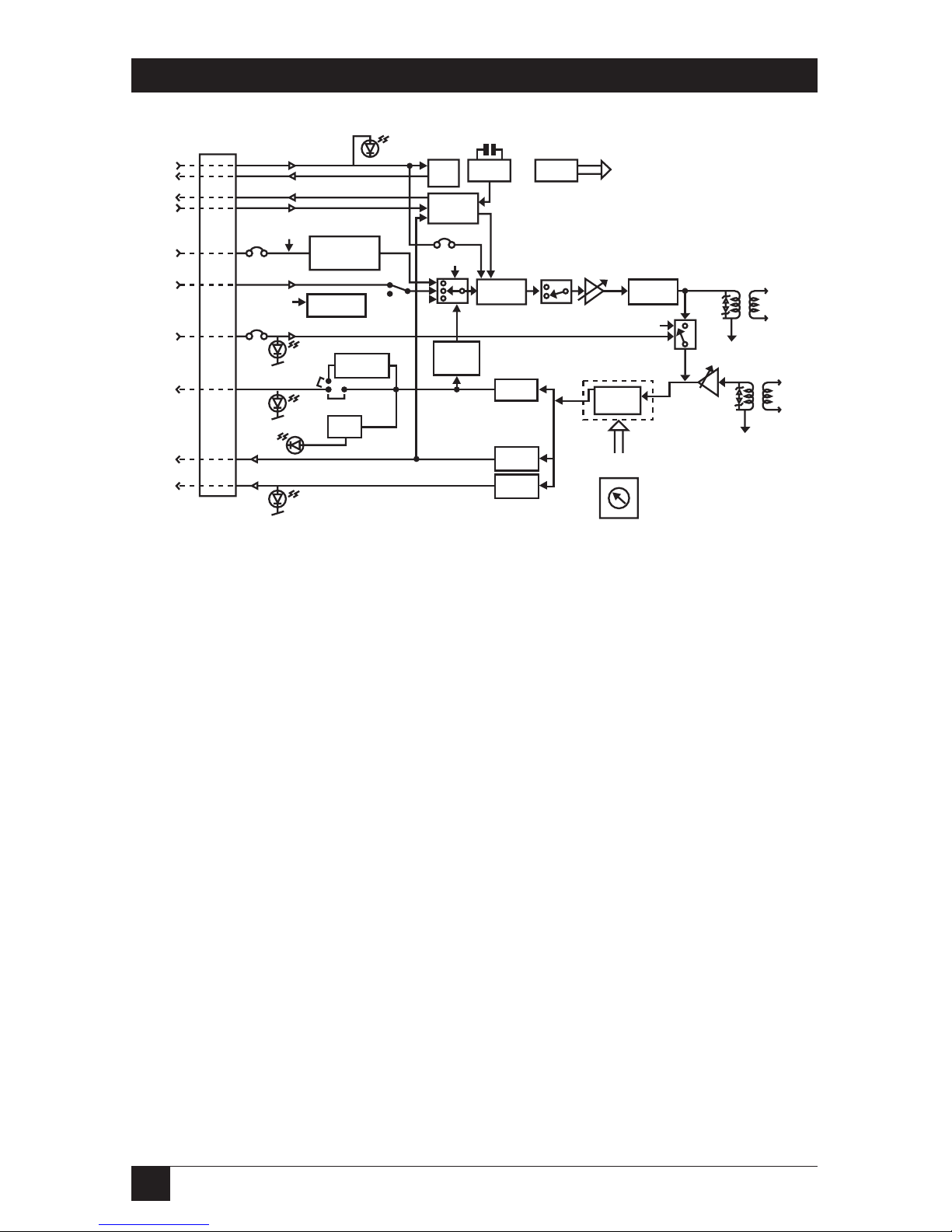
This section contains the functional descriptions of the LDM-144LR circuit
blocks, primarily those circuits that are required to set the correct
configuration of the modem. For the block diagram, see Figure 2-1.
Page 13
12
LDM-144LR
Figure 2-1. LDM-144LR Block Diagram.
2.3.1 E
NCODER
M
ODULATOR
The Encoder Modulator receives data from the DTE and modulates it by
means of the partial-response modulation technique. The Encoder
Modulator can operate in one of the following modes:
• 4-wire full-duplex
• 4-wire half-duplex
2.3.2 M
ODULATION
T
IMING
This circuit supplies the transmit clock to the Encoder Modulator. Three
clock sources are available:
• The modem’s internal crystal oscillator, INT
• The DTE clock, EXT
• The receive signal recovered clock, RCV
Setting the transmit clock jumper (J1) determines the timing mode of the
LDM-144LR.
CTS
Delay
OSC
Power
Supply
Modulation
Timing
REM
COMMAND
GENERATOR
RTS
BERT
ERROR
Encoder
Modulation
REM
COMMAND
GENERATOR
V.5 4
Diagnostics
PATT
REM
RTS
CTS
TXC
EXT
CLK
TXD
REM
ANA
RXD
TXD
TXD
CNT/ON
DIG
Encoder
Modulation
Transmit
Filter
Selectable Level
Transmit Filter
Loopback
Timing
RLB
Command
Decoder
Decoder
Timing
Recovery
Carrier
Detect
DATA
RATE
Automatic
Equalizer
ANA
TX
TX
Selectable Level
Receiv Amplifier
DIG
LPBK
5
6
7
3
2
1
4
0
Page 14

13
LDM-144LR
2.3.3 S
ELECTABLE
L
EVELTRANSMITAMPLIFIER
Two options are available for the transmit signal level: 0 and -6 dBm. The
transmit signal level is controlled by the XMT LEVEL jumper (J11). Receive
signal gain is controlled by the RCV LVL jumper (J9) and has two selectable
options: 0 and -6 dBm.
2.3.4 V.54 D
IAGNOSTICS
V.54 loops are activated either by the manual front panel push-buttons or
through the DTE interface. The push-button controlled loopbacks can be
enabled or disabled by the SWITCH jumper (J2), while the DTE controlled
remote and analog loopbacks are enabled and disabled by the RLB (J6) and
the ALB (J5) jumpers respectively. When the LDM-144LR is used as a tail-end
to a digital network, the V.54 DLY jumper (J7) in the modem closest to the
network is set to ON to prevent other equipment from receiving the V.54 data
sequence and inducing it into the loop.
2.3.5 T
EST
P
ATTERNGENERATOR ANDRECEIVER
The Test Pattern Generator enables easy and quick testing of the local
modem and the communication link. When the PATT pushbutton on the
front panel is activated, the circuit sends a standard 511-bit pseudo-random
pattern and checks its response. If errors are detected, the ERR indicator
remains ON or blinks.
The test can be carried out in local analog loopback, in remote digital
loopback, or in normal point-to-point operation opposite a remote LDM144LR. For the latest test to take place, press the PATT pushbutton on the
remote unit or connect a Bit Error Rate Tester BERT, which generates and
receives a standard pseudo-random 511-bit pattern.
2.3.6 S
ELECTABLECARRIERDETECTSENSITIVITY
Carrier Detect Sensitivity is controlled by the CD SENS jumper (J4). Setting
J4 to LOW will activate DCD over short ranges. Setting J4 to HIGH will
activate DCD up to the ranges in Table 2-1.
Page 15

14
LDM-144LR
Table 2-1. Typical Range.
Data Rate 19AWG (0.9 mm) 22 AWG (0.6 mm) 24 AWG (0.5 mm) 26 AWG (0.4 mm)
(kbps) km miles km miles km miles km miles
48 26.4 16.5 16 10 11 6.8 8 5
56 25.2 15.7 15.2 9.5 10.5 6.5 7.5 4.5
64 24 15 14.5 9 10 6.2 7.3 4.7
72 21.6 14.6 13 8.1 9 7 7 4.6
96 20.4 14.2 12.3 7.7 8.5 5.3 6.8 4.5
112 19.2 12 11.5 7.2 8 4.9 5.7 3.4
128 18 11.2 10.8 6.8 7.5 4.7 5 3.3
144 16.8 10.5 10.1 6.4 7 4.3 4.8 3.2
2.4 Applications
Figures 2-2 and 2-3 illustrate the LDM-144LR in a variety of configurations,
each suitable for a particular application.
Page 16

15
LDM-144LR
Figure 2-2. Point-to-Point Configuration.
Figure 2-3. X.21 Digital Network Tail-end.
ASM-24
RCV CLK
V.54 DLY - Off
EXT CLK
V.54 DLY - On
EXT CLK
V.54 DLY - On
RCV CLK
V.54 DLY - Off
ASM-24 ASM-24
ASM-24
X.21
Digital
Service
Network
ASM-24 ASM-24
4-wire
Up to 26.4 km
48-144 kbps
LDM-144LR LDM-144LR
Page 17

16
LDM-144LR
3. Standalone Installation
3.1 General
The standalone version can be either set on a flat surface or mounted in a
rack. The height of the unit is 1U (1.75"H), the width of the unit is slightly
less than half the available mounting width. A rack adapter kit is available for
installing either a single unit or two units side by side in the 19" rack. This
chapter provides the information required to install the standalone LDM144LR unit. To install the rack-mounted unit (ME447C), see Chapter 3.
After the installation has been completed, refer to Chapter 4 for operating
information and system checkout to assume normal operation.
3.2 Site Preparation
The LDM-144LR is installed within 5 ft. (1.5 m) of a grounded AC outlet
and must be situated within 50 ft. (15 m) of the associated data terminal
(for the V.35 model, the unit should be even closer to the terminal).
Allow at least 36 in. (90 cm) of frontal clearance for accessibility during
operations and maintenance. Ensure at least 4 in. (10 cm) clearance at
the rear of the unit for signal lines and interface cables.
3.3 Mechanical Assembly
The LDM-144LR standalone version is designed to be placed on a table top
or bench, and is delivered in a completely assembled format. No provision
is made for bolting the LDM-144LR to the table top.
3.4 Electrical Installation
3.4.1 P
OWERCONNECTION
AC power is supplied to the LDM-144LR through a standard 3-prong plug
with integral fuse holder (see Figure 3-1).
The rated fuse for the unit is 250/.0.125A slow-blow for 230 volts live
voltage, or 250/0.250 A slow-blow for 115 volts live voltage.
DC power is supplied to the LDM-144LR via a 3-pin male connector.
A male to female adapter is supplied with the product (see Figure 3-2).
Page 18

17
LDM-144LR
WARNING
GROUNDING: This unit should always be grounded through the
protective earth lead of the power cable.
When connecting AC power to this unit, the mains plug should only be
inserted in a socket outlet provided with a protective earth contact. The
protective action must not be negated by use of an extension cord
(power cable) without a protective conductor (grounding). Interrupting
the protective (grounding) conductor (inside or outside the unit), or
disconnecting the protective earth terminal can make this unit
dangerous.
The line fuse is located in an integral-type fuse holder located on the rear
panel (as shown in Figure 3-1). Make sure that only fuses of the required
rating, as marked on the rear panel, are used for replacement. Do not
use repaired fuses or short-circuit the fuse holder. Always disconnect
the mains cable before removing or replacing the fuse.
Whenever it is likely that fuse protection has been damaged, make the
unit inoperative and secure it against unintended operation.
3.4.2 R
EARPANELCONNECTORS
The rear panel connectors located on the LDM-144LR are shown in Figure
3-1. The connectors comprise the DTE interface connector and the line
connector. The DTE interface is a field-changeable module and has a
true-type connector. The line connector is a terminal block.
Page 19

18
LDM-144LR
Figure 3-1. LDM-144LR Rear Panel Connectors.
3.4.3 DTE I
NTERFACESIDE
The DTE side provides interfaces for input/output data, clock, and control
signals between the LDM-144LR and the DTE.
NOTE
Detailed information on the DTE Interface Signal Assignments is given in
Appendix B.
V.24/RS-232
The V.24/RS-232 interface connector, D-type has a standard 25-pin, pinout
configuration.
V.35 Interface
The V.35 interface connector has a standard 34-pin pinout configuration.
DTE
-230V / 0.1A T 250V
100-115
V
A
C
-0.2A
T 250
XMTXMT RCV GND
Line Fuse
Page 20

19
LDM-144LR
RS-530/RS-449
The RS-530/RS-449 D-type connector has a standard 25-pin pinout. For a
description of the cabling connection between the RS-530 interface and the
RS-449/RS-442 (V.36) 37-pin, D-type connector (see Appendix C). The cable
is provided with the product.
3.4.4 S
TRAP
S
ELECTION
Although most of the modem configuration can be monitored and changed
via the front panel, there are straps that have to be set before you use the
modem. When the electrical installation has been completed and checked,
determine the required configuration of the LDM-144LR and position the
straps accordingly. The PCB strap locations of Figure 3-5 correspond to the
numbers listed under “PCB Name” in Table 3-1.
WARNING
Disconnect the AC power cord before removing the unit’s cover.
Installation, operation, and maintenance should be performed by an
experienced technician.
3.4.5 I
NSTALLATION OFINTERNALJUMPERS ANDSWITCHES
Before electrical installation, the LDM-144LR’s internal jumpers and switches
should be set according to the application. To access the internal jumpers
and switches:
1. Disconnect the AC power cord.
2. Lay the unit upside-down on a soft surface. (At the ends of both the left
and right sides, the plastic locking clips can be seen.)
3. With the tip of a flat screwdriver (or similar object), depress the plastic
housing-locking clips in turn, while gently prying the two halves apart.
4. Now separate the halves completely, taking care not to lose the two black
plastic side-strips.
Page 21

20
LDM-144LR
Figure 3-2. LDM-144LR Switch and Jumper Settings.
ON
CNTRL
BAUD RATE
(kbps)
XMT CLK
RCV
INT
EXT
CARR
LOW
HIGH
CD SENS
A
L
B
EN
DIS
R
L
B
J1
J4
SW1
J2
J3
J5
J6
0
dBm
-6
XMT IMPXMT LEVEL
HIGH
LOW
J12
J11
J13
CHASS
DIS
CON
RTS-CTS DLY
70 MS
8 MS
J8
V54 DLY
DTE COMM.
ON
OFF
J7
ON
OFF
SW. ENABLE
0
dBm
-6
RCV IMP
RCV LVL
150
HIGH
J9 J10
Page 22

21
LDM-144LR
Table 3-1. LDM-144LR Switch and Jumper Settings.
PCB Function Details Option Factory
Name Setting
J1 XMT CLK Selects the transmit timing RCV
signal from either internal INT INT
clock, external clock, or
receive clock.
J2 SW, ENABLE When set to ON, enables SWITCH: ON ON
activation of Diagnostics SWITCH: OFF
through the front-panel
pushbuttons.
J3 CARR When set to ON, the transmit CARR: ON ON
carrier is permanently CARR: CNTRL
activated.
J4 CD SENS Controls Carrier detect CD SENS: LOW
sensitivity level. LOW: for CD SENS: HIGH HIGH
short ranges. HIGH: for
ranges up to the product
limitation.
J5 [DTE COMM.] When set to ENabled, the ALB: EN EN
ALB Analog Loopback signal ALB: DIS
from the DTE is enabled.
J6 [DTE COMM.] When set to ENabled, the RLB: EN EN
RLB Remote Loopback signal RLB: DIS
from the DTE is enabled.
Page 23

22
LDM-144LR
Table 3-1. LDM-144LR Switch and Jumper Settings (continued).
PCB Function Details Option Factory
Name Setting
J7 V54 DLY When set to ON, the V.54 V54 DLY: ON ON
is activated to prevent V54 DLY: OFF
multiple loopback to tail-end
circuits.
J8 RTS-CTS Selects the delay between DLY: 70 ms
DLY RTS and CTS. DLY: 8 ms 8 ms
J9 RCV LVL Selects receive level into the RCV LVL: 0 dBm 0 dBm
modem. 0 dBm for ranges RCV LVL: -6 dBm
up to the product limitation.
-6 dBm for short ranges.
J10 RCV IMP Selects the receive-line RCV IMP: 150Ω 150Ω
impedance. RCV IMP: HIGH
J11 XMT LEVEL Selects the transmit output XMT LEVEL:
level to the line. 0 dBm for 0 dBm 0 dBm
ranges up to the product XMT LEVEL:
limitation. -6 dBm for -6 dBm
short ranges.
J12 XMT IMP Selects the transmit line XMT IMP: HIGH
LOW: Up to 150 Ω XMT IMP: LOW LOW
HIGH: Higher than 150 Ω
J13 CHASS When set to CONnect, the CHAS GND: DIS
the Signal Ground is CHAS GND: CON CON
connected to the Chassis
Ground.
Page 24

23
LDM-144LR
Table 3-1. LDM-144LR Switch and Jumper Settings (continued).
PCB Function Details Option Factory
Name Setting
SW1 BAUD RATE Selects the data rate in kbps 0-144 kbps
(kbps) 1-128 kbps
2-112 kbps
3-96 kbps
4-72 kbps
5-64 kbps 64 kbps
6-56 kbps
7-48 kbps
NOTE
We recommend configuring the Transmit Timing (XMT CLK) of one unit
to the receive clock (RCV), and the other unit to either internal (INT) or
external (EXT) clock.
3.4.6 L
INESIDE
The terminal block provides four connecting points to the transmit and
receive twisted-pair lines, and a fifth for ground connection. The transmit
and receive pairs are polarity-insensitive.
The transmit pair is connected to the terminals marked XMT (data output
of the modem), and the receive pair is connected to the terminals marked
RCV (data input to the modem).
Page 25

24
LDM-144LR
Figure 3-3. Wire Insertion Details.
XMT RCV GND
Wire Insertion Details
1) Insert screwdriver into square hole.
2) Raise inserted screwdriver,
putting pressure on the
ramp within the square hole.
The wire clamp within the
round hole will open.
3) Insert the stripped end of the wire
and remove the screwdriver.
Page 26

25
LDM-144LR
4. Standalone Operation
4.1 General
This chapter provides the necessary information to operate the LDM-144LR
unit. For information specific to the rack-mounted unit, see Chapter 6.
4.4 Controls and Indicators
All control (pushbutton) switches and indicators (LEDs) are located on the
front panel, as shown in Figure 4-1. The control and indicator functions are
described in Table 4-2.
4.3 Operating Procedure
NOTE
When the unit power is turned on, operating personnel are exposed to
voltages below 30 volts on the card or any accessible area of the modem
except the mains power socket.
4.3.1 P
OWERINGON
To apply AC power:
1. Connect the AC power cable to the LDM-144LR mains socket and to an
approved AC source. Check that the green PWR indicator is turned on.
2. If the local and remote LDM-144LR units are operational and passing
data, check that the following indication states exist:
Page 27

26
LDM-144LR
Table 4-1. Indication States.
Indicator State
PWR On
RTS On or Flashing
TD Flashing or Off
RD Flashing or Off
DCD On or Flashing
TEST Off
ERR Off
3. If the above indications are not obtained as a result of the initial
powering up, verify that the three test pushbuttons, DIG, ANA and REM,
are not depressed.
Page 28

27
LDM-144LR
Table 4-2. Controls and Indicators.
Designation Control/Indicator Function
PWR Indicator, green When turned on, indicates that the unit is
powered.
RTS Indicator, yellow When turned on, indicates that an active
RTS signal is issued by the DTE.
TD Indicator, yellow When turned on, indicates that a steady
“space” signal is being transmitted. When
data is transmitted, the indicator flickers.
RD Indicator, yellow When turned on, indicates that a steady
“space” is being received. When data is
received, the indicator flickers.
DCD Indicator, yellow When turned on, indicates a valid receive
signal according to the detected carrier.
TEST Indicator, red When turned on, indicates that the
LDM-144LR is set to one of the three
loopback modes or that the internal BER
test is activated.
ERR Indicator, yellow The ERR LED is active only when the
internal BER tester is activated. If errors
are detected in the test pattern, the ERR
indicator blinks or remains in the on state.
Page 29

28
LDM-144LR
Table 4-2. Controls and Indicators (continued).
DIG Control When depressed, loops the local
LDM-144LR receiver output back to its
transmitter, as shown in Figure 5-3.
The looped data is synchronized to the
transmit clock.
The DSR signal is set to the low state.
ANA Control When depressed, loops the local
LDM-144LR transmitter output back to
its receiver, as shown in Figure 5-1 (Analog
Loopback per V.54, loop 3) This loopback
may also be activated from the DTE when
“DTE Command ALB” jumper is set to EN.
REM Control When depressed, loops the remote
LDM-144LR receiver output back to its
transmitter, as shown in Figure 5-2 (Remote
Digital Loopback per V.54, loop 2). The
looped data is synchronized to the transmit
clock. This loopback may also be activated
from the DTE when “DTE Command RLB”
jumper is set to RLB EN.
PATT Control When depressed, the LDM-144LR transmits
and receives a 511-bit test pattern. If errors
are detected in the received pattern, the
ERR indicator is turned on or blinks. The
Receive Data and CTS signals are set to
the low state.
Page 30

29
LDM-144LR
4.3.2 S
ELF
T
EST
In order to verify that the LDM-144LR is operating correctly, perform the
internal BERT and analog loopback tests detailed in Section 5-2 and Section
5-3 respectively.
4.3.3 O
PERATION
With the exception of occasional monitoring of indicators, the LDM-144LR
is operated unattended.
4.3.4 T
URNINGOFFPOWER
To turn off the AC power, simply remove the AC power cable from the
AC source.
4.4 Field Settings of Jumpers and Switches
WARNING
Disconnect the AC power cord before removing the unit’s cover.
Installation, operation and maintenance of the unit should be performed
by an experienced technician.
Before re-configuring the LDM-144LR to a different operation mode, set
the board switches and jumpers to the corresponding states. Resetting of
switches and jumpers according to Table 3-1 should be performed by an
experienced technician.
Figure 4-1. Front Panel.
PWR RTS TD RD DCD TEST ERR
DIG ANA REM PATT
LDM-144LR
Page 31

30
LDM-144LR
5. Tests and Diagnostics
5.1 General
This chapter contains procedures for performing system diagnostics and faultisolation for both the LDM-144LR and LDM-144LR Card units.
• The LDM-144LR features CCITT V.54 diagnostic capabilities for
performing local analog loopback and local and remote digital loopbacks.
• The loopbacks can be activated by either the front-panel push buttons or
by control signal from the digital interface.
• The LDM-144LR has a built in BER tester and pattern generator which
can be activated via the front panel switches.
5.2 V.54 Loop Tests
The LDM-144LR supports three types of loopbacks for checking the
communication between the attached equipment and the local modem, and
the communication between the modems. Use the test procedures provided
in this chapter to verify normal system operation and to isolate faulty
equipment in the event of failure.
NOTE
Before testing the operation of the data-system equipment and its line
circuits, make sure that all units are turned on and configured correctly.
Loop tests are best performed in the order presented here.
5.2.1 L
OCALTEST
—L
OCALANALOGLOOPBACK
(ANA)
The local Analog loopback (ANA) test checks the performance of the local
LDM-144LR modem, the local data terminal and the connections between
them as shown in Figure 5-1. It is performed separately at the local and the
remote site.
1. Activate the ANA loopback (see Table 4.1 for activation instructions).
The TEST indicator should light. The LDM-144LR digital interface is
now connected to its own DTE data output via most of the modem
circuits. (This test can also be activated via the appropriate pin on the
digital interface.)
Page 32

31
LDM-144LR
NOTE
Activation of ANA loopback via the appropriate pin on the digital
interface is not available when using X.21 interface.
2. Verify that the data terminal equipment is operating properly and can be
used for a test. Do not perform tests with faulty equipment. Before
performing a test, either have the equipment repaired or replace it with a
functioning unit.
3. Execute the test with one of the methods described below:
• Using the DTE and checking the echoed data stream.
• Using an external Bit Error Rate Tester (BERT) unit.
4. Perform Step 3 above at both ends. If the BERT test indicates correct
operation, but the data terminal indicates a fault, follow the
manufacturer’s test procedures for the data terminal and verify the cable
connection between the terminal and the LDM-144LR. After completion
of the test (or when the fault has been corrected), de-activate the ANA
loopback test.
Figure 5-1. Local LDM-144LR in Analog Loopback.
DATA
TERMINAL
DATA
ANA pressed
DATA
XMTR
LINE
RCVR
CLK
CLK
Z
0
Z
I
Page 33

32
LDM-144LR
5.2.2 R
EMOTE
D
IGITALLOOPBACK
(REM)
The Remote digital loopback (REM) test determines the performance of both
the local and the remote LDM-144LR units, as well as their connecting lines.
The Remote Digital Loopback test consists of providing a loopback at the
remote modem, as shown in Figure 5-2.
1. Activate the REM loopback (see Table 4-1 for activation instructions) to
provide a loopback at the remote LDM-144LR. The TEST indicator
should light at both the local and remote unit. (This test can also be
activated via the appropriate pin on the digital interface.)
2. Perform the BERT test as explained in Section 5.2.1, steps 3 and 4.
3. If step 2 indicates a fault, while the local analog loopback test described
in Section 5.2.1 was successful for both the local and remote modems,
then the line or the line circuits of the local or the remote unit are not
functioning properly. To verify that the LDM-144LR is operating
correctly, follow the instructions below:
• Press the ANA (Analog Loopback) pushbutton on the front panel and
check that both the TEST and DCD indicators are turned on.
• If the DCD indicator is not turned on, check that the Carrier jumper J3
(CARR), is set to ON or that the RTS signal is high.
• Press the PATT pushbutton and check the following indications:
- If the ERR indicator remains turned on or blinks, then the LDM-144LR is
faulty; replace it.
- If the indications are as specified in step 3 above, restore the push-buttons
to the operation mode.
Page 34

33
LDM-144LR
Figure 5-2. LDM-144LR in Remote Digital Loopback.
5.2.3 L
OCALDIGITALLOOPBACK
(DIG)
The Local digital loopback (DIG) consists of looping the received data back
to the remote LDM-144LR, as shown in Figure 5-3. Using this test, the
operator at the remote end can determine the performance of the local and
remote LDM-144LR units, and the communication lines interconnecting
them.
Figure 5-3. Local LDM-144LR in Digital Loopback.
RCVR
XMTR
LOCAL
DATA
TERMINAL
RCVR
XMTR
REMOTE ASM-24LOCAL ASM-24
REMOTE
DATA
TERMINAL
DATA
DIG pressed
CLK
CLK
DATA
DATA
REM pressed
CLK
CLK
DATA
RCVR
XMTR
LOCAL
DATA
TERMINAL
RCVR
XMTR
REMOTE ASM-24LOCAL ASM-24
REMOTE
DATA
TERMINAL
LOCAL LDM-144LR
REMOTE LDM-144LR
LOCAL LDM-144LR
REMOTE LDM-144LR
Page 35

34
LDM-144LR
6. Card Version
6.1 RM110A Description
The RM110A consists of one or two power supplies and up to 14 plug-in
cards. The card types can be LDM-144LR or other modem cards, (any mix
of up to 14 plug-in cards). The rear panel consists of a snap connector and a
DB25 D-type connector. The snap connector provides for connecting the
transmit and receive lines. The transmit pair is connected to the terminals
marked XMT, the receive pair is connected to the terminals marked RCV,
and an optional ground connection is the fifth screw.
The interface connector is a 25-pin female connector, which provides all
interface signals for the digital interfaces. Two optional interface
attachments, the CIA/V.35 and CIA/X.21 are available, providing two V.35
34-pin connectors or two X.21 15-pin connectors respectively (see Figure
6-3).
Figure 6-1. Front Panel of the Card Version.
PWR
RTS
TD
RD
DCD
SG
DIG
ANA
REM
PATT
LDM-144LR
Page 36

35
LDM-144LR
6.2 LDM-144LR Card Version
The LDM-144LR Card is a card version of the LDM-144LR medium-range
modem. The card indicator LEDs and test push-buttons of each LDM-144LR
Card are conveniently located on the front panel, shown in Figure 6-1,
enabling indicator LEDs to be clearly visible. See Chapter 3 for card jumper
setting and Chapter 4 for card operation information.
6.3 Power Supply
6.3.1 AC S
UPPLY
(110 OR230 VAC)
The power supply accepts 110 or 230 volts AC, ±10%, 47 to 63 Hz, and
consists of a power switcher, AC plug, operating switch and indicator LEDs.
The indicator LEDs show activity when the AC power supply is connected to
the mains plug, and the switch is on. Each LDM-144LR Card has two fuses
which protect the entire system against power failure in the event of a short
circuit in one of the cards.
6.3.2 DC S
UPPLY
(-48 VDC)
The power supply accepts 36–72 volts DC and consists of a DC/DC converter
module that provide the power required for the cards. This power supply
supports a full card cage with any combination of cards.
6.3.3 P
OWERSUPPLY WITHREDUNDANCY
This special ordering option power supply is equipped with two separate
power supplies, operating together and sharing the load of the whole card
cage. If either one of the power supplies fails, the other will continue to
supply power for a full card cage. The redundant power supply can be AC or
DC and can operate with AC or DC main power supply. LED indicators shows
activity of each power supply. The LED should light when mains power is
provided.
Page 37

36
LDM-144LR
Figure 6-2. RM110A Card Cage.
NOTE
It is possible to combine AC and DC power supplies in the same cage.
6.4 Installation
6.4.1 E
LECTRICAL
I
NSTALLATION
Follow the jumper set-up procedures in Section 3.4.5. The rear panel is
shown in Figure 6-3.
6.4.2 M
ECHANICAL
I
NSTALLATION
After installing the RM110A in the 19" rack, the LDM-144LR cards should be
inserted into it. Once the cards have been inserted, the nut on the top and
bottom of each card should be tightened to ensure that it is fully inserted into
the edge connector, inside the rack.
ON
ON
Dual,
Redundant,
Hot-
Swappable
Power Supply
Page 38

37
LDM-144LR
6.5 Operation
The power supply is controlled from the power module on the left-hand side
of the rear panel of the RM110A (see Figure 6-3).
Figure 6-3. RM110A Rear Panel.
M14
M1
M2
M3
M4
M5
M6
M7
M8
M9
M10
M11
M13
M12
GND
RCV
XMT
Page 39

38
LDM-144LR
Appendix A: IR-G.703 Co-Directional
64-kbps Interface
IR-G.703 Co-Directional Interface
The IR-G.703 is an interface module for modems, converting G.703 codirectional signals to TTL levels. The converted data is sent over the modem
link using the modem’s modulation technique and is converted back at the
other end into G.703 64-kbps co-directional signals, or any other possible
digital interface signals.
The module is available in two versions: for stand-alone modems and for
rack modems. The stand-alone version fits into a stand-alone modem, and is
available with two types of physical connections: terminal block or RJ-45. The
rack version mounts on the rack-version modem card, and uses the modem’s
edge connector for communication. The edge connector is wired on the
motherboard of the card cage to a DB25 connector on the back panel.
Figure A-1 illustrates the pinout of the different connectors.
NOTE
Rcv, in Figure A-1 refers to the input signals to the IR module, XMT refers
to the output signals from the module.
The approximate range between the IR G.703 module and the attached
G.703 equipment is up to 500 meters over 24 AWG cable (depending on
cable quality used).
The G.703 interface module has two operation modes, TX-FIFO and RXFIFO, which are strap-selectable on the board (see Figure A-1).
Page 40

39
LDM-144LR
Figure A-1. IR G.703 Connector Options.
The G.703 interface module has two operation modes, TX-FIFO
and RX-FIFO, which are strap-selectable on the board (see Figure A-2).
Figure A-2. Strap-Selectable Operation Modes.
TX FIFO
RX FIFO
Terminal Block
or RJ-45 in the
Stand-alone version
RCV (3,6)
(4,5)
XMT
18
(9,11) RCV
(2,16) XMT
(7) GND
DTE
-230V / 0.1A T 250V
100-115 VAC
-0.2A T 250
Line Fuse
RCV GNDXMTXMTGND RCV
Terminal Block (Standalone)
RJ-45
(Standalone)
DB25
(Rack Version)
Page 41

40
LDM-144LR
M
ODE
A: TX-FIFO
This mode is used in tail-end applications of G.703 co-directional networks.
In this application, system timing is provided by the G.703 network. The IRG.703 module has an internal buffer to compensate for the phase delay
introduced to the system by the line delay occurring between the two
modems. The buffer is a 2-bit FIFO buffer and is connected as shown in
Figure A-3.
Figure A-3. TX-FIFO Block Diagram.
Timing Source
TX Data
TX
TX
RX
RX
RX Data
G.703
Co-directional
64 kbps network
Buffer
EXT Clock Mode RCV Clock Mode
Clock In
Clock
Out
Modem A Modem B
Clock
Recovery
Data
Clock
Recovery
IR-G.703 Module
Clock
Recovery
Page 42

41
LDM-144LR
M
ODE
B: RX-FIFO
This mode is used in applications where the G.703 co-directional 64-kbps side
recovers the clock from the modem link. This mode is used mainly when the
attached equipment has a G.703 co-directional interface, but no ability to
produce clock. The module has a 2-bit FIFO buffer for compensating for the
phase delay introduced by the G.703 device. Figure A-4 illustrates the buffer
connection and the required application set-up. Other clock modes are
available in addition to the one shown in Figure A-4. The only restriction
is that the clock source must be MODEM B, or the clock should be recovered
by MODEM B from the DTE side.
Figure A-4. RX-FIFO Block Diagram.
TX
RX
RX Data
TX Data
TX
RX
INT or EXT
Clock Mode
EXT or INT
Clock Mode
(Dependent on the
attached network)
Modem A
Equipment
with G.703
interface
LINK
side
G.703
side
DTE
side
RCV Clock Mode
Modem B
Clock In
Clock
Out
IR-G.703 Module
Data
Clock
Recovery
Buffer
Clock
Recovery
Page 43

42
LDM-144LR
Appendix B: RS-422 Interfacing Pinout
Table B-1. LDM-144LR EIA 530 Pinout Connection (Digital Interface
to DTE RS-422 [V.36] DTE Interface).
Function DTE RS-422/423 (RS-499) LDM-144LR
37 Pin Connector SD DB25 Female Connector
Pin Circuit Pin Circuit
Protective Ground 1 Shield 1
Signal Ground 19, 37, 20 7 AB
Transmitted Data 4 SD (A) 2 BA (A)
22 SD (B) 14 BA (B)
Received Data 6 RD (A) 3 BB (A)
24 RD (B) 16 BB (B)
Request to Send 7 RS (A) 4 CA (A)
25 RS (B) 19 CA (B)
Clear to Send 9 CS (A) 5 CB (A)
27 CS (B) 13 CB (B)
Data Set Ready 11 DM (A) 6 CC (A)
29 DM (B) 22 CC (B)
Data Terminal Ready 12 TR (A) 20 CD (A)
30 TR (B) 23 CD (B)
Carrier Detect 13 RR (A) 8 CF (A)
31 RR (B) 10 CF (B)
Page 44

43
LDM-144LR
Table B-1. LDM-144LR EIA 530 Pinout Connection (continued).
Function DTE RS-422/423 (RS-499) LDM-144LR
37 Pin Connector SD DB25 Female Connector
Pin Circuit Pin Circuit
External Transmit 17 TT (A) 24 DA (A)
Clock 35 TT (B) 11 DA (B)
Transmit Clock 5 ST (A) 15 DB (A)
23 ST (B) 12 DB (B)
Receive Clock 8 RT (A) 17 DD (A)
26 RT (B) 9 DD (B)
Local Analog Loopback 10 LL 18 LL
Remote Loopback 14 RL 21 RL
Test Indicator 18 TM 25 TM
Page 45

44
LDM-144LR
Appendix C: Unit Case Assembly
Installation of the Unit Case into a 19" Rack
G
ENERAL
The height of the unit is 1U (1.75"); the width of the unit is slightly less than
half the available mounting width. Rack adapter kits, RM516-RM523, are
available for installing either a single unit or two units side by side in the 19"
rack.
NOTE
Disconnect AC power before opening the unit. Installation, operation
and maintenance of this unit should only be performed by an
experienced technician.
I
NSTALLATION OF A
S
INGLEUNIT
Rack-adapter components for installing a single unit include one short
bracket and one long bracket. Each bracket is fastened to the side walls of
the unit by two screws, which are inserted into the two front holes on the side
wall. (The unit is supplied with nuts already in place on the inner side wall.)
Note that the short bracket fastens to the left side of the unit, and the long
bracket to the right side of the unit (see Figure D-1).
Once the brackets are fastened to the side walls, the unit is ready for
installation in the 19" rack. Place the unit in the rack and fasten the brackets
to the side rails of the rack by means of the two screws situated on each side
(not included in the kit).
Page 46

45
LDM-144LR
Figure D-1. Installation of a Single Unit.
I
NSTALLATION OFTWOUNITS
Rack-adapter components for installing two units include two long side rails
(one for each unit), which slide one into the other, fastening the two units
together; and two short side brackets, which hold the two units in the 19"
rack (see Figure D-2).
Figure D-2. Installation of Two Units, Part 1.
Page 47

46
LDM-144LR
Two-unit installation instructions
1. Fasten one long side rail to each unit (one to the right side of one unit,
the other to the left side of the other unit) using the four screws and
flatwashers supplied. The side rails must be attached in opposing fashion,
the narrow flange of the first rail opposite the wide flange of the second
rail.
2. Attach one short bracket opposite the side rail on each unit using the
four screws supplied.
3. Slide the side rail of one unit into the side rail of the other unit, fastening
the two units together (see Figure D-3).
4. Secure the supplied plastic caps to the ends of the rails, to prevent the
units moving and to protect the rail ends.
5. Place the assembled units in the rack and fasten the brackets to the side
rails of the rack, by means of the four screws situated on each side (not
included in the kit).
Figure D-3. Installation of Two Units, Part 2.
Page 48

1000 Park Drive • Lawrence, PA 15055-1018 • 724-746-5500 • Fax 724-746-0746
© Copyright 1997. Black Box Corporation. All rights reserved.
 Loading...