

Page 1
CUSTOMER
SUPPORT
INFORMATION
Order toll-free in the U.S. 24 hours, 7 A.M. Monday to midnight Friday: 877-877-BBOX
FREE technical support, 24 hours a day, 7 days a week: Call 724-746-5500 or fax 724-746-0746
Mail order: Black Box Corporation, 1000 Park Drive, Lawrence, PA 15055-1018
Web site: www.blackbox.com • E-mail: info@blackbox.com
MARCH 1998
ME375A-R2
ME375AE-R2
ME376A-R2
ME376AE-R2
Async/Sync 2-Wire Short Haul Modem
ASYNC/SYNC 2-WIRE SHORT HAUL MODEM
DIG
ANA
PWR
RTS
TD
RD
DCD
LOS
ERR
TEST
REM
PATT
RESET
Page 2

3
FCC/IC RFI STATEMENTS, SAFETY WARNING
FEDERAL COMMUNICATIONS COMMISSION
AND
CANADIAN DEPARTMENT OF COMMUNICATIONS
RADIO FREQUENCY INTERFERENCE STATEMENTS
This equipment generates, uses, and can radiate radio frequency energy and if not
installed and used properly, that is, in strict accordance with the manufacturer’s
instructions, may cause interference to radio communication. It has been tested
and found to comply with the limits for a Class A computing device in accordance
with the specifications in Subpart J of Part 15 of FCC rules, which are designed to
provide reasonable protection against such interference when the equipment is
operated in a commercial environment. Operation of this equipment in a
residential area is likely to cause interference, in which case the user at his own
expense will be required to take whatever measures may be necessary to correct the
interference.
Changes or modifications not expressly approved by the party responsible for
compliance could void the user’s authority to operate the equipment.
This digital apparatus does not exceed the Class A limits for radio noise emission from digital
apparatus set out in the Radio Interference Regulation of the Canadian Department of
Communications.
Le présent appareil numérique n’émet pas de bruits radioélectriques dépassant les limites
applicables aux appareils numériques de classe A prescrites dans le Règlement sur le brouillage
radioélectrique publié par le ministère des Communications du Canada.
SAFETY WARNING
Always observe standard safety precautions during installation, operation, and
maintenance of this product. If you attempt to remove the power-supply fuse, be
sure to disconect the power cord from the power source first, in order to avoid the
possibility of electric shock.
Page 3

4
ASYNC/SYNC 2-WIRE SHORT-HAUL MODEMS
NORMAS OFICIALES MEXICANAS (NOM)
ELECTRICAL SAFETY STATEMENT
INSTRUCCIONES DE SEGURIDAD
1. Todas las instrucciones de seguridad y operación deberán ser leídas antes de
que el aparato eléctrico sea operado.
2. Las instrucciones de seguridad y operación deberán ser guardadas para
referencia futura.
3. Todas las advertencias en el aparato eléctrico y en sus instrucciones de
operación deben ser respetadas.
4. Todas las instrucciones de operación y uso deben ser seguidas.
5. El aparato eléctrico no deberá ser usado cerca del agua—por ejemplo, cerca
de la tina de baño, lavabo, sótano mojado o cerca de una alberca, etc..
6. El aparato eléctrico debe ser usado únicamente con carritos o pedestales que
sean recomendados por el fabricante.
7. El parato eléctrico debe ser montado a la pared o al techo sólo como sea
recomendado por el fabricante.
8. Servicio—El usuario no debe intentar dar servicio al equipo eléctrico más allá
a lo descrito en las instrucciones de operación. Todo otro servicio deberá ser
referido a personal de servicio calificado.
9. El aparato eléctrico debe ser situado de tal manera que su posición no
interfiera su uso. La colocación del aparato eléctrico sobre una cama, sofá,
alfombra o superficie similar puede bloquea la ventilación, no se debe colocar
en libreros o gabinetes que impidan el flujo de aire por los orificios de
ventilación.
Page 4

5
NOM STATEMENT
10. El equipo eléctrico deber ser situado fuera del alcance de fuentes de calor
como radiadores, registros de calor, estufas u otros aparatos (incluyendo
amplificadores) que producen calor.
11. El aparato eléctrico deberá ser connectado a una fuente de poder sólo del
tipo descrito en el instructivo de operación, o como se indique en el aparato.
12. Precaución debe ser tomada de tal manera que la tierra fisica y la polarización
del equipo no sea eliminada.
13. Los cables de la fuente de poder deben ser guiados de tal manera que no
sean pisados ni pellizcados por objetos colocados sobre o contra ellos,
poniendo particular atención a los contactos y receptáculos donde salen del
aparato.
14. El equipo eléctrico debe ser limpiado únicamente de acuerdo a las
recomendaciones del fabricante.
15. En caso de existir, una antena externa deberá ser localizada lejos de las lineas
de energia.
16. El cable de corriente deberá ser desconectado del cuando el equipo no sea
usado por un largo periodo de tiempo.
17. Cuidado debe ser tomado de tal manera que objectos liquidos no sean
derramados sobre la cubierta u orificios de ventilación.
18. Servicio por personal calificado deberá ser provisto cuando:
A: El cable de poder o el contacto ha sido dañado; u
B: Objectos han caído o líquido ha sido derramado dentro del aparato; o
C: El aparato ha sido expuesto a la lluvia; o
D: El aparato parece no operar normalmente o muestra un cambio en su
desempeño; o
E: El aparato ha sido tirado o su cubierta ha sido dañada.
Page 5

6
ASYNC/SYNC 2-WIRE SHORT-HAUL MODEMS
Contents
Chapter Page
1. Specifications ............................................................................................. 7
2. Introduction ............................................................................................. 10
3. Installation ................................................................................................ 11
3.1 Placement .......................................................................................... 11
3.2 Setting the Internal Controls ........................................................... 11
3.3 Connecting the Data Cables ............................................................. 16
3.4 Connecting to AC Power .................................................................. 17
4. Operation ................................................................................................. 19
4.1 The Front-Panel Controls and Indicators ....................................... 19
4.2 Power-Up, Normal Operation, and Power-Down ........................... 22
4.3 Reconfiguration ................................................................................ 23
5. Troubleshooting ...................................................................................... 24
5.1 Diagnostic Testing ............................................................................ 24
5.2 Calling Black Box .............................................................................. 28
5.3 Shipping and Packaging ................................................................... 28
Appendix: Pinouts .......................................................................................... 29
Legal Information ........................................................................................... 33
Page 6

7
CHAPTER 1: Specifications
1. Specifications
Compliance — FCC Part 15 Subpart J Class A, DOC Class/MDC classe A
Standard — T1: ANSI T1.601.1988
Interfaces — ME375 models: 2-wire telco, EIA RS-232;
ME376 models: 2-wire telco, ITU-TSS (CCITT) V.35
Protocols — DTE side: Synchronous or asynchronous;
Line side: 2B1Q encoding
Clock Source — Internal, external (from DTE), or received (from other
unit), user-selectable
Data Format — 7 or 8 data bits; 1 or 2 stop bits; even, odd, or no parity
(user-selectable)
Operation — Line side: Full duplex with echo cancellation
Data Rate — 128, 115.2, 64, 57.6, 48, 38.4, 19.2, 9.6, 4.8, 2.4, 1.2, and
0.6 Kbps
Transmission
Level — Up to 14 dBm
Maximum
Distance — DTE side:
ME375 models: 50 ft. (15.2 m);
ME376 models: 25 ft. (7.6 m);
Line side: 3.4 mi. (5.5 km) over 26-AWG wire,
independent of data rate
Page 7

8
ASYNC/SYNC 2-WIRE SHORT-HAUL MODEMS
User Controls — (5) Front-mounted:
(4) Pushbuttons: DIG (local digital loopback), ANA
(local analog loopback), REM (remote digital
loopback), and PATT (test pattern);
(1) Recessed RESET switch;
(6) Internal:
(1) 7-position DIP switch for protocol, data format,
and signaling options;
(1) Rotary switch for data rate;
(4) Jumpers for clock source, loopback testing, and
ground connection
Diagnostics — V.54-compliant loopback tests:
Local analog loopback (switch- or signal-triggerable);
Local digital loopback (switch-triggerable);
Remote digital loopback (switch- or signal-triggerable)
Indicators — (8) Front-mounted LEDs: PWR (power), RTS, TD, RD,
DCD, LOS (loss of signal), ERR (error), and TEST
Connectors — ME375 models: (1) RJ-45 female, (1) 3-clip terminal
block, and (1) DB25 female;
ME376 models: (1) RJ-45 female, (1) 3-clip terminal
block, and (1) 34-pin M-block female
Leads/Signals
Supported — See the Appendix
Power — From internal power supply through included or
alternate 5-ft. (1.5-m) power cord:
ME375A-R2, ME376A-R2:
Input: 103.5 to 131.5 VAC, 47 to 63 Hz;
ME375AE-R2, ME376AE-R2:
Input: 207 to 253 VAC, 47 to 63 Hz;
Consumption: 5 VA
Page 8

9
CHAPTER 1: Specifications
Fuse — ME375A-R2, ME376A-R2: 0.1-A slow-blow;
ME375AE-R2, ME376AE-R2: 0.2-A slow-blow
Other Power
Protection — AC/DC overvoltage-protection circuits connected
through transformers to transmit and receive leads on
the line side, plus special gas diodes
MTBF — 75,500 hours
Maximum
Altitude — 8000 ft. (2438.4 m)
Temperature
Tolerance — 32 to 122˚ F (0 to 50˚ C)
Humidity
Tolerance — Up to 90% noncondensing
Enclosure — High-impact plastic
Size — 1.8"H x 7.6"W x 9.6"D (4.6 x 19.3 x 24.3 cm), but the
unit’s pushbuttons protrude up to 0.1" (25 mm) from
the front panel and the connectors protrude up to 0.8"
(1.9 cm) from the rear panel
Weight — Net: 3.1 lb. (1.4 kg);
Shipping: 6 lb. (2.7 kg)
Page 9

10
ASYNC/SYNC 2-WIRE SHORT-HAUL MODEMS
2. Introduction
The Async/Sync 2-Wire Short Haul Modem (A/S2W SHM) operates synchronously
or asynchronously at high speeds (600 bps to 128 Kbps) and in full duplex over
one pair of dedicated telephone lines. It has a range of 3.4 miles (5.5 km) over
26-AWG wire.
The A/S2W SHM operates in full duplex over 2 wires by using the adaptive
“echo-canceling” technique. Because it also uses 2B1Q line coding, it can achieve
the range mentioned above no matter what the data rate is.
The A/S2W SHM incorporates interface circuits for the terminal/computer, an
adaptive echo-canceler, an automatic adaptive equalizer, a modulator, and a
demodulator. It is coupled to the telephone line through an isolation transformer,
which protects against AC or DC overvoltages. The protection circuitry would
enable the unit to operate even if DC were accidentally connected to the line.
The A/S2W SHM has diagnostic capabilities: It can perform local analog
loopback and local and remote digital loopback. The operator at either end of the
line may test both modems and the line in the remote digital loopback mode.
Loopback can be controlled with either the unit’s front-panel pushbuttons or
signals passed through the DTE (PC, data-terminal) interface.
Page 10

11
CHAPTER 3: Installation
3. Installation
This chapter tells you how to configure and install the Async/Sync 2-Wire Short
Haul Modem. After you finish doing this, refer to Chapter 4 for operating
information.
3.1 Placement
The Async/Sync 2-Wire Short Haul Modem is designed to be placed on a tabletop,
shelf, or bench, and is delivered completely assembled. (No provisions are made
for bolting the A/S2W SHM to any surface.)
The A/S2W SHM should be installed within 1.5 m (5 ft) of a grounded AC
outlet and must be situated within 25 ft. (7.6 m—ME376 models) or 50 ft. (15 m—
ME375 models) of the associated data terminal.
Allow at least 36" (90 cm) of clearance in front of the unit so you can access it
during operation and maintenance. Make sure that there is at least 4" (10 cm) of
clearance behind the unit for signal lines and interface cables.
3.2 Setting the Internal Controls
Before you install any cabling and definitely before you plug in the unit, you
should set the Async/Sync 2-Wire Short Haul Modem’s internal controls to suit
your application. (If you don’t feel comfortable about doing this yourself, get an
experienced technician to do it or to help you.) To access the internal controls,
first make sure the A/S2W SHM is disconnected from AC power, then unscrew the
two screws on the unit’s rear panel and slide the bottom half of the unit out from
beneath its cover.
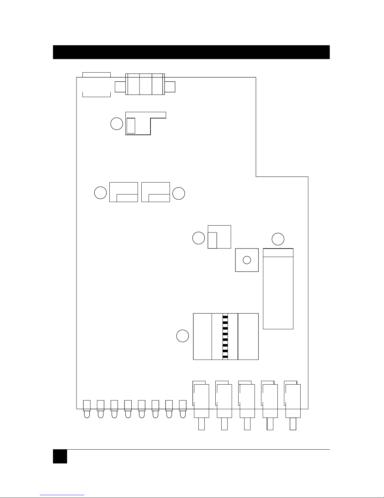
Refer to Figure 3-1 on the next page and Table 3-1 on the succeeding pages for
the locations of the controls and their possible settings respectively.
Page 11
12
ASYNC/SYNC 2-WIRE SHORT-HAUL MODEMS
DSR
DCD
1STB
EVEN
P.EN
8BIT
ASY
DTR
CNT
2STB
ODD
DIS
7BIT
SYNC
9MS
CLOCK
LBT
INT
EXT
SW
7
0 0.6K
1 1.2K
2 2.4K
3 4.8K
4 9.6K
5 19.2K
6 38.4K
7 48K
8 56K
9 64K
A 128K
POS BAUD
D
IS
EN
R
LB
DIS
EN
LLB
CHASS-GND
CON
DIS
1
2
3
4
5
6
ON
Figure 3-1. The A/S2W SHM’s internal controls and indicators.
Page 12

13
CHAPTER 3: Installation
Table 3-1. Possible Settings of Internal Controls
Callout Description Position/Label Possible FactoryNo. in Settings Default
Fig. 3-1 Setting
1 DIP Switch Position 1 Async or sync Sync
ON = ASYNC operation
OFF = SYNC
Position 2 8 or 7 data bits 8 bits
ON = 8BIT
OFF = 7BIT
Position 3 Parity enabled Disabled
ON = PRTY or disabled
OFF = DIS
Position 4 Even or odd Even
ON = EVEN parity
OFF = ODD
Position 5 1 or 2 stop bits 1 bit
ON = 1STB
OFF = 2STB
Position 6* DCD independent DCD ind.
ON = DCD or controlled by
OFF = CNT RTS
Position 7† DSR always ON or DSR ON
ON = DSR follows DTR
OFF = DTR
*If DIP Switch Position 6 is set to:
• DCD: The DCD signal is ON as long as the local unit is in proper
synchronization with the remote unit. The DCD signal is OFF when
digital loopback is active or when there is no synchronization (for
example, while the unit is receiving the remote loopback command).
• CNT: The local unit’s DCD signal follows the remote unit’s RTS signal.
†If DIP Switch Position 7 is set to:
• DSR: The DSR signal is ON as long as the local unit is receiving AC
power; it does not indicate the existence of a communication channel
or the status of the remote site.
• DTR: The local unit’s DSR signal follows the remote unit’s DTR signal.
Page 13

14
ASYNC/SYNC 2-WIRE SHORT-HAUL MODEMS
Table 3-1. Possible Settings of Internal Controls (cont’d.)
Callout Description Position/Label Possible FactoryNo. in Settings Default
Fig. 3-1 Setting
2 Data-Rate Position 0 0.6K 0.6 Kbps
Dial* Position 1 1.2K 1.2 Kbps
Position 2 2.4K 2.4 Kbps
Position 3 4.8K 4.8 Kbps
Position 4 9.6K 9.6 Kbps
Position 5 19.2K 19.2 Kbps
Position 6 38.4K 38.4 Kbps
Position 7 48K 48 Kbps
(Position 8 56K)† (56 Kbps)
Position 9 64K 64 Kbps
64 Kbps (P9)
Position A 128K 128Kbps
(Position B 144K)† (144 Kbps)
Position C 57.6K** 57.6 Kbps
Position C 115.2K** 115.2 Kbps
*Setting this dial has no effect or purpose if the unit is set to use the
external clock.
†These data-rate settings are not supported by the standard A/S2W SHM.
If you need to transfer data at one of these speeds, call Black Box
Technical Support for a special quote on a unit that will.
**These settings (popular speeds for direct computer-to-computer
communication) do not work properly unless the A/S2W SHM
communicates with the DTE asynchronously (DIP Switch Position 1 set to
ON).
Page 14

15
CHAPTER 3: Installation
Table 3-1. Possible Settings of Internal Controls (cont’d.)
Callout Description Function/Label Possible FactoryNo. in Settings Default
Fig. 3-1 Setting
3 Clock-Source For master units, select INT INT
(CLOCK) either internal timing (INT) EXT
Jumper or external timing (EXT). LBT
For slave units, always select
loopback (received) timing
(LBT).
4 Local Enable/disable control of DIS DIS
Loopback local analog loopback EN
(LLB) testing with signals from
Jumper* the DTE
5 Remote Enable/disable control of DIS DIS
Loopback remote digital loopback EN
(RLB) testing with signals from
Jumper* the DTE
6 Chassis- Tie Signal Ground to Chassis CON CON
Ground (Protective, Frame) Ground DIS
(CHASS_ or isolate the two grounds
GND) from each other
Jumper
*Only connect the RLB and LLB jumpers (that is, set them to EN [enabled])
if you want to be able to turn local analog or remote digital loopbacks on
and off from the DTE using the proper RS-232 or V.35 signals. The settings
of these jumpers have no effect on the ANA and REM pushbutton switches
on the unit’s front panel; you will be able to control loopback testing with
those buttons whether these jumpers are connected or not. (There is no
way to control local digital loopback through the local DTE interface; you
must use the DIG button to do that.)
Page 15

16
ASYNC/SYNC 2-WIRE SHORT-HAUL MODEMS
3.3 Connecting the Data Cables
To connect your data cables to the Async/Sync 2-Wire Short Haul Modem, take
these steps, referring to Figure 3-2 below:
1. Connect the twisted-pair transmission line to the two clips marked LINE (or
Pins 4 and 5 of the RJ-45 connector) and (optionally) the cable shield to the
clip marked GND (or Pin 2 of the RJ-45 connector). If you are using the
connecting the line to the clips, refer to Wire-Insertion Details on the next
page. We highly recommend that for your transmission line you use twistedpair cable capable of supporting high data rates, especially Category 3 or
better, in order to prevent crosstalk. Our product code for a type of cable that
fits the bill, bulk unterminated Category 5 UTP, is EYN717A (specify the
length you want).
2. Run the DTE-side cable from the DTE to the A/S2W SHM. If your A/S2W
SHM is an ME375 model, this cable should be straight-through-pinned and 50
or fewer feet (15.2 or fewer meters) long; it should also have a DB25 female
connector on the DTE end and a DB25 male connector on the A/S2W SHM
end. (Our product code for this type of cable is ECM25C; specify the length
you want and “male-female” genders).
If your A/S2W SHM is an ME376 model, this cable should be straightthrough-pinned and 25 or fewer feet (7.6 or fewer meters) long; it should also
have a 34-pin M-block male connector on the A/S2W SHM end. (Our
product code for this type of cable is EYN450; specify the length and genders
you want.)
Fig. 3-2. The A/S2W SHM’s rear panel.
DTE
LINE
GND
24 5
100-115 VAC/
0.2A T 250
230V/ O.1A T 250V
Page 16

17
CHAPTER 3: Installation
3.4 Connecting to AC Power
AC power is supplied to the A/S2W SHM through an included or alternate 1.5-m
(5 ft) cord terminated with a grounded plug. Make sure that, before you plug the
cord into the unit and an outlet, that proper grounding rules are observed:
• If you are using an alternate cord, it must have a ground wire that runs from
the unit’s ground (earth) terminal (the topmost of the three prongs on the
unit’s IEC 320 male power inlet) to the ground terminal on the outlet.
• Do not use an extension cord with the unit unless it also has a ground wire
that runs between ground terminals at either end.
Once you are sure of proper grounding, run the power cord from the A/S2W
SHM’s IEC320 male power inlet to a working outlet. As soon as the cord is plugged
in at both ends, the unit will begin operating, because it has no power switch. (To
turn the unit on and off, you must plug it in and unplug it.) The PWR LED should
light; see Section 4.2.
Wire Insertion Details
1) Insert screwdriver into square hole.
2) Raise inserted screwdriver,
putting pressure on the
ramp within the square hole.
The wire clamp within the
round hole will open.
3) Insert the stripped end of the wire
and remove the screwdriver.
LINE
GND
24 5
Page 17

18
ASYNC/SYNC 2-WIRE SHORT-HAUL MODEMS
While the A/S2W SHM is ON, operating personnel are not exposed to more
than 30 volts on any card or on any accessible area of the DC power supply.
Nevertheless, never open the unit or try to maintain or reconfigure it while it is
plugged in.
The AC cord is fused at the rear panel of the unit. If this fuse blows, make sure
you replace it only with a fuse rated for the required current and of the specified
type (0.2-A slow-blow for ME375A-R2 and ME376A-R2, 0.1-A slow-blow for
ME375AE-R2 and ME376AE-R2). An extra fuse should have been included with
the unit. Until you replace a blown, damaged, or missing fuse, unplug the unit and
make sure that no one attempts to use it. Avoid using repaired fuses, and never
“get by” without the fuse by short-circuiting the fuse holders!
Page 18

19
CHAPTER 4: Operation
4. Operation
This chapter lists the Async/Sync 2-Wire Short Haul Modem’s external controls
and indicators, describes their functions, and describes operating procedures.
Complete and confirm the installation procedures described in Chapter 3 before
you attempt to operate the A/S2W SHM. If you have difficulty, refer to Chapter 5.
4.1 The Front-Panel Controls and Indicators
FIgure 4-1 below shows the front panel of the Async/Sync 2-Wire Short Haul
Modem, including all of the controls and LED indicators mounted on it. These
controls and indicators are described in Tables 4-1 and 4-2 on the next two pages.
Fig. 4-1. The A/S2W SHM’s front panel.
Page 19

20
ASYNC/SYNC 2-WIRE SHORT-HAUL MODEMS
Table 4-1. Front-Panel Controls and Their Functions
Control Function
DIG Press this Local Digital Loopback button to cause the local A/S2W
SHM to loop received data and clock signals from the line back
out of its own transmitter. This is equivalent to activating remote
digital loopback (see below) on the remote unit. Press this button
again to terminate local digital loopback.
ANA* Press this Local Analog Loopback button to cause the local
A/S2W SHM to loop its transmitter output back into its own
receiver. Press this button again to terminate local analog
loopback. While the A/S2W SHM’s LLB jumper is set to EN
(enabled—see the third part of Table 3-1 on page 15), you can
also control this type of loopback by raising and lowering the LL
signal from the DTE on the appropriate pin for your interface.
REM* Press this Remote Digital Loopback button to cause the remote
A/S2W SHM to loop received data and clock signals back out of
its own transmitter. (Data Set Ready goes low when this
happens.) Press this button again to terminate remote digital
loopback. While the A/S2W SHM’s RLB jumper is set to EN
(enabled—see the third part of Table 3-1 on page 15), you can
also control this type of loopback by raising and lowering the RL
signal from the DTE on the appropriate pin for your interface.
PATT Press this Pattern button to cause the local A/S2W SHM to send
the remote unit a continuous Bit Error Rate test pattern. Press this
button again to stop sending the test pattern.
RESET Carefully press a long thin object such as a tack or the end of a
paper clip into this recessed switch to reset the A/S2W SHM. Do
this to clear abnormal conditions (the indication of an error
condition, for example) instead of unplugging the unit and plugging
it back in.
*The ANA and REM buttons are not affected by the settings of the RLB and
LLB jumpers (see the third part of Table 3-1 on page 15). Even if those
jumpers are set to DIS (disabled), you can still control loopback testing with
these buttons.
Page 20

21
CHAPTER 4: Operation
Table 4-2. Front-Panel Indicators and Their Functions
Indicator ITU-TSS Function
(CCITT)
Circuit
PWR Green LED is steadily lit while power is present.
RTS 105 Yellow LED is steadily lit while the Request to Send
(RTS) signal from the DTE is high.
TD 103 Yellow LED is steadily lit while the local A/S2W
SHM transmits steady SPACE. It flickers while the
local unit transmits data.
RD 104 Yellow LED is steadily lit while the local A/S2W
SHM receives steady SPACE. It flickers while the
local unit receives data.
DCD 109 Yellow LED is steadily lit while:
a) The local and remote A/S2W SHMs are in sync,
and the local unit’s DCD switch is set to “DCD”;
b) The local and remote A/S2W SHMs are in sync,
the local unit’s DCD switch is set to “CNT”, and the
remote unit has RTS high.
LOS Red LED is steadily lit when synchronization
between the local and remote A/S2W SHMs is lost.
ERR Red LED is steadily lit when the local A/S2W SHM’s
PATT button is in the ON position (depressed) and
the unit detects an error in the BERT pattern.
TEST Yellow LED is steadily lit while the local A/S2W
SHM’s internal BERT is active (the PATT button is
depressed) or the unit is in any of the three
loopback modes.
Page 21

22
ASYNC/SYNC 2-WIRE SHORT-HAUL MODEMS
4.2 Power-Up, Normal Operation, and Power-Down
Making sure that you follow the guidelines in Section 3.4, power up the
Async/Sync 2-Wire Short Haul Modem by plugging its AC power cord to an
working AC outlet. (The unit has no power switch. To power it down, unplug it.)
The PWR LED should light, indicating that the unit is on.
If the local and remote A/S2W SHM units are both operating and transmitting
data, the units’ front-panel indicators should look like this:
PWR Steadily lit
TD Steadily lit or flickering depending on the data being transmitted.
RD Steadily lit or flickering depending on the data being received.
RTS Steadily lit or dark depending on the status of the RTS signal from the
local DTE.
DCD If the local unit’s DCD jumper is set to DCD, steadily lit; if the local unit’s
DCD jumper is set to CNT, steadily lit or dark depending on the status
of the RTS signal from the remote unit.
LOS Flashing until the units synchronize with each other, then dark.
ERR Flashing until the units synchronize with each other, then dark.
TEST Flashing until the units synchronize with each other, then dark.
If the LEDs don’t look like this, make sure that:
• One A/S2W SHM’s CLOCK jumper is set to internal (INT) or external (EXT)
clock, and the other unit’s CLOCK jumper is set to loopback (LBT) clock.
• Both units’ four front-panel pushbuttons are in the OFF position (not
depressed).
Once a A/S2W SHM begins operating normally, it will continue to do so
indefinitely without needing to be attended, except when occasional monitoring of
LED indicators is required. If you have difficulty, perform the diagnostic tests
described in Section 5.1. If you still can’t solve the problem, call Black Box as
described in Section 5.2.
Page 22

23
CHAPTER 4: Operation
4.3 Reconfiguration
If it becomes necessary to reconfigure your A/S2W SHMs for a different type of
operation, you will have to reposition the units’ internal controls. (If you don’t feel
comfortable about doing this yourself, get an experienced technician to do it or to
help you.) Take these steps:
1. Unplug the local unit and temporarily detach the data cables from it.
3. Open the unit’s cover.
4. Referring to Figure 3-1 on page 12 and Table 3-1 on pages 13 through 15, set
the unit’s internal controls to suit the new application.
5. Close the cover.
6. Perform Steps 1 through 5 at the remote site.
7. Reattach the data cables to both units and plug both units back in.
The A/S2W SHMs should begin operating with their new parameters. If there are
problems, make sure that both units are set correctly. If they are, perform the
diagnostic tests described in Section 5.1. If you still can’t solve the problem, call
Black Box as described in Section 5.2.
Page 23

24
ASYNC/SYNC 2-WIRE SHORT-HAUL MODEMS
5. Troubleshooting
5.1 Diagnostic Testing
If you have problems with data communication on your Async/Sync 2-Wire Short
Haul Modem system, or if you just want to verify proper system operation, the
A/S2W SHM has diagnostic capabilities that can help you. You can use the A/S2W
SHM’s front-panel pushbuttons to control different kinds of tests with which you
can quickly check the A/S2W SHM, the attached cables (including the
transmission line), and the local DTE. By performing these tests, you can quickly
find out which components of your A/S2W SHM system are operating properly
and which aren’t.
Before you begin testing, make sure that both of the A/S2W SHMs and both
DTEs are powered up and configured normally. When you have verified this,
perform the tests described in Sections 5.1.1, 5.1.2, and 5.1.3, in that order.
5.1.1 L
OCALANALOGLOOPBACK
Use this test to check the performance of the local modem, the local DTE, and the
cables between them. Perform this test separately at both the local and remote sites
(refer to Figure 5-1 on the next page). Take these steps:
1. Push the local A/S2W SHM’s ANA (Local Analog Loopback) button or (if the
unit’s LLB jumper is set to EN) raise the LL signal from the DTE to the unit.
The unit should light its TEST LED as it internally connects its transmitter
output to its own receiver circuits.
2. Verify that the DTE is operating properly and can be used for a test. If the
DTE is malfunctioning, replace it or have it repaired.
3. Observe what happens to test data that you send and get back: Set the DTE to
half duplex and get an “echo” through the system and/or use special Bit
Error Rate Test (BERT) equipment.
Page 24

25
CHAPTER 5: Troubleshooting
Fig. 5-1. Local analog loopback.
4. If you use a BERT unit and it indicates an error, make sure the cables
connecting it to the A/S2W SHM are securely connected. If they are, try
swapping in known-good cables. If the error goes away, the problem was
probably in the old cables. Otherwise, the A/S2W SHM is probably faulty; call
Black Box for technical support.
If you use a BERT unit and it indicates all clear, but you get errors when
you perform the DTE test, the DTE is probably the source of the problem.
Make sure that it is physically intact and that it is configured correctly. Refer
to your DTE’s manual if necessary, and if you can’t solve the problem, call
your DTE’s supplier.
If you don’t have a BERT unit, and the DTE test indicates an error, make
sure the cables connecting the DTE to the A/S2W SHM are securely
connected. If they are, try swapping in known-good cables. If the error goes
away, the problem was probably in the old cables. Otherwise, the DTE is
probably the source of the problem. Make sure that it is physically intact and
that it is configured correctly. Refer to your DTE’s manual if necessary, and if
you can’t solve the problem, call your DTE’s supplier.
5. After completing the test (or when the fault has been corrected), return the
ANA button to the OFF position by pushing it again or, if you’re controlling
the test electronically, lower the LL signal from the DTE to the unit.
6. Repeat Steps 1 through 5 at the remote site.
Proceed with the Remote Digital Loopback test.
DATA
TERMINAL
CLK
DATA
DATA
CLK
XMTR
RCVR
LINE
Page 25

26
ASYNC/SYNC 2-WIRE SHORT-HAUL MODEMS
5.1.2 R
EMOTEDIGITALLOOPBACK
Use this test to determine how the line-side circuits of the local and remote A/S2W
SHMs and the 2-wire line between them are performing:
1. Push the local unit’s REM (Remote Digital Loopback) pushbutton or (if the
unit’s RLB jumper is set to EN) raise the RL signal from the DTE to the unit.
The TEST LED should light on both units as the local unit sends a remoteloopback command to the remote unit and the remote unit internally
connects its receiver input to its transmitter output (see Figure 5-2 below).
2. Perform a DTE test and/or BERT as described in Step 3 of the Local Analog
Loopback procedure. You can also press the local unit’s PATT button to have
it send a test pattern through the loop. (Press the PATT button again to stop
the test pattern.)
3. If Step 2 indicates a fault, but Local Analog Loopback testing was successful
for both A/S2W SHMs, either the line connection between the units is faulty,
or the 2-wire line circuits inside one or both of the units are not operating
properly. If possible, try a different line. If this is impossible, or if the problem
does not go away when you use a different line, call Black Box for technical
support.
4. After completing the test (or when the fault has been corrected), return the
REM button to the OFF position by pushing it again or, if you’re controlling
the test electronically, lower the RL signal from the DTE to the unit.
Proceed with the Local Digital Loopback test.
Fig. 5-2. Remote digital loopback.
LOCAL
DATA
TERMINAL
REMOTE
DATA
TERMINAL
RLB active
DATA
CLK
XMTR
XMTR
RCVR
RCVR
CLK
DATA
Page 26

27
CHAPTER 5: Troubleshooting
5.1.3 L
OCALDIGITALLOOPBACK
This test is essentially the same as the Remote Digital Loopback test, but
performed “in reverse,” so to speak. It allows you to make doubly sure of the line
and the A/S2W SHMs’ line-side circuitry by setting up a loop in the opposite
direction. Take these steps:
1. Push the local unit’s DIG (Local Digital Loopback) pushbutton. (There is no
way to initiate this test electronically.) The TEST LED should light on both
units as the local unit sends a local-loopback notification to the remote unit
and then internally connects its receiver input to its transmitter output (see
Figure 5-3 below).
2. The operator at the remote site can test the units and the lines and take
remedial action as described in Steps 2 and 3 of the Remote Digital Loopback
procedure.
3. When the operator at the remote site notifies you that he or she has finished,
return the DIG button to the OFF position by pushing it again.
If you have been unable to solve the problem, call Black Box for technical support
as described in the next section.
Fig. 5-3. Local digital loopback.
REMOTE
DATA
TERMINAL
LOCAL
DATA
TERMINAL
DIG active
DATA
CLK
XMTR
XMTR
RCVR
RCVR
CLK
DATA
Page 27

28
ASYNC/SYNC 2-WIRE SHORT-HAUL MODEMS
5.2 Calling Black Box
If you determine that your Async/Sync 2-Wire Short Haul Modem is
malfunctioning, do not attempt to alter or repair it. It contains no user-serviceable
parts. Contact Black Box Technical Support at 724-746-5500; the problem might be
solvable over the phone.
Before you do, make a record of the history of the problem. We will be able to
provide more efficient and accurate assistance if you have a complete description,
including:
• The nature and duration of the problem.
• When the problem occurs.
• The components involved in the problem.
• Any particular application that, when used, appears to create the problem or
make it worse.
• The results of any testing you’ve already done.
5.3 Shipping and Packaging
If you need to transport or ship your Async/Sync 2-Wire Short Haul Modem:
• Package it carefully. We recommend that you use the original container.
• Before you ship a unit for repair or return, contact Black Box to get a Return
Materials Authorization (RMA) number, and make sure you include
everything you received with the unit when you ship it.
Page 28

ITU-TSS EIA Signal Name/ ITU-TSS Signal Name/ Description
(CCITT) RS-232 Abbreviation for V.35 Abbreviation for
V.24 Pin EIA RS-232 Pin(s) ITU-TSS V.35
Circuit (ME375) (ME375) (ME376) (ME376)
101 1 Protective Ground A Frame Ground (FGND) Chassis ground. May be
(PGND) connected to or isolated
from Signal Ground by
setting the GROUND
jumper.
102 7 Signal Ground (SGND) B Signal Ground (SGND) Signal ground. May be
connected to or isolated
from Protective/Frame
Ground by setting the
GROUND jumper.
103 2 Transmit Data (TD) P Send Data A (SD A) Serial digital data received
S Send Data B (SD B) from the DTE. In
synchronous applications,
the data transitions must
occur on the rising edge of
the transmit clock.
104 3 Receive Data (RD) R Receive Data A (RD A) Serial digital data sent to
T Receive Data B (RD B) the DTE. In synchronous
applications, the data
transitions occur on the
rising edge of the clock.
105 4 Request to Send (RTS) C Request to Send (RTS) The DTE raises this signal
to the A/S2W SHM when it
wants to transmit data.
106 5 Clear to Send (CTS) D Clear to Send (CTS) The A/S2W SHM raises
this signal to the DTE
when it is ready to receive.
29
APPENDIX: Pinouts
Appendix: Pinouts
The table below and on the following pages describes the leads and signals
supported by the two models of the Async/Sync 2-Wire Short Haul Modem.
Page 29

30
ASYNC/SYNC 2-WIRE SHORT-HAUL MODEMS
ITU-TSS EIA Signal Name/ ITU-TSS Signal Name/ Description
(CCITT) RS-232 Abbreviation for V.35 Abbreviation for
V.24 Pin EIA RS-232 Pin(s) ITU-TSS V.35
Circuit (ME375) (ME375) (ME376) (ME376)
107 6 Data Set Ready (DSR) E Data Set Ready (DSR) If DIP Switch Position 7 is
set to DSR, the A/S2W
SHM holds this signal high
unless it is in digital
loopback or receives a
remote-loopback signal
from the remote unit.
If DIP Switch Position 7
is set to DTR, the A/S2W
SHM lets this signal follow
(reflect) the remote unit’s
DTR.
108.2 20 Data Terminal Ready H Data Terminal Ready The DTE raises this signal
(DTR) (DTR) when it is ready to transmit
or receive. If the remote
unit’s DIP Switch Position
7 is set to DTR, the remote
unit’s DSR will follow
(reflect) this signal.
109 8 Received Line Signal F Received Line Signal More commonly known as
Detector (RLSD) Detector (RLSD) Data Carrier Detect (DCD).
The A/S2W SHM holds
this signal high unless
RTS goes low or carrier is
lost.
113 24 Transmitter Signal U Serial Clock Transmit More commonly known as
Element Timing [DTE] Exetrnal A (SCTE A) External Clock (EXC). The
(TSETT) W Serial Clock Transmit DTE sends this data-rate
External B (SCTE B) clock signal to the A/S2W
SHM, which in turn passes
it to the remote unit. The
A/S2W SHM derives its
sync clock from this signal
only if its CLOCK jumper is
set to EXT. Positive clock
transitions correspond to
positive data transitions.
Page 30

31
APPENDIX: Pinouts
ITU-TSS EIA Signal Name/ ITU-TSS Signal Name/ Description
(CCITT) RS-232 Abbreviation for V.35 Abbreviation for
V.24 Pin EIA RS-232 Pin(s) ITU-TSS V.35
Circuit (ME375) (ME375) (ME376) (ME376)
114 15 Transmitter Signal Y Serial Clock Transmit A More commonly known as
Element Timing [DCE] (SCT A) Transmit Clock (TXC). The
(TSETC) AA Serial Clock Transmit B A/S2W SHM sends this
(SCT B) data-rate clock signal to
the DTE and the remote
unit. The A/S2W SHM
derives its sync clock from
this signal only if its
CLOCK jumper is set to
INT. Positive clock
transitions correspond to
positive data transitions.
115 17 Receiver Signal V Serial Clock Receive A More commonly known as
Element Timing [DCE] (SCR A) Receive Clock (RXC). The
(RSETC) X Serial Clock Receive B remote A/S2W SHM sends
(SCR B) this data-rate clock signal
to the lccal unit, which in
turn passes it to the DTE.
The A/S2W SHM derives
its sync clock from this
signal only if its CLOCK
jumper is set to LBT.
Positive clock transitions
correspond to positive
data transitions.
140 21 Remote Loopback (RL) HH Remote Loopback (RL) The DTE raises this signal
to the A/S2W SHM to
cause it to begin and
maintain remote digital
loopback (V.54 Loop 2).
The A/S2W SHM ignores
this signal unless its RLB
jumper is set to EN.
141 18 Local Loopback (LL) JJ Local Loopback (LL) The DTE raises this signal
to the A/S2W SHM to
cause it to begin and
maintain local analog
loopback (V.54 Loop 3).
The A/S2W SHM ignores
this signal unless its LLB
jumper is set to EN.
Page 31

32
ASYNC/SYNC 2-WIRE SHORT-HAUL MODEMS
ITU-TSS EIA Signal Name/ ITU-TSS Signal Name/ Description
(CCITT) RS-232 Abbreviation for V.35 Abbreviation for
V.24 Pin EIA RS-232 Pin(s) ITU-TSS V.35
Circuit (ME375) (ME375) (ME376) (ME376)
142 25 Test Mode (TM) KK Test Mode (TM) The A/S2W SHM raises
this signal during any test
and any time its internal
BERT is activated (the
PATT button is
depressed).
Page 32

33
LEGAL INFORMATION
DISCLAIMERS
No representation for fitness of this product for any purpose other than those
specifically mentioned in this manual is made either by the manufacturer or its
agents.
The manufacturer shall not be liable for any direct, indirect, special, incidental,
or consequential damages, whether based on contract, tort, or any legal theory.
RESERVED RIGHTS
This document contains materials protected by copyright, including information
belonging to the manufacturer. All rights are reserved. No part of this manual may
be reproduced or transmitted in any form, by any means or for any purpose,
without express written consent.
The manufacturer and its agents reserve the right to revise this publication or
make changes without obligation to notify any person of such revisions or changes.
Page 33

NOTES
Page 34

1000 Park Drive • Lawrence, PA 15055-1018 • 724-746-5500 • Fax 724-746-0746
©Copyright 1998. Black Box Corporation. All rights reserved.
 Loading...