

Black Box ME260A, ME262C, ME268C, ME263C, ME265C Owner's Manual
...
CUSTOMER
SUPPORT
INFORMATION
Order toll-free in the U.S. 24 hours, 7 A.M. Monday to midnight Friday: 877-877-BBOX
FREE technical support, 24 hours a day, 7 days a week: Call 724-746-5500 or fax 724-746-0746
Mail order: Black Box Corporation, 1000 Park Drive, Lawrence, PA 15055-1018
Web site: www.blackbox.com • E-mail: info@blackbox.com
AUGUST 2000
ME260A ME265C
ME260AE ME266C
ME261C ME267C
ME262C ME268C
ME263C
Modular Modem Eliminator
T
D
-1
P
W
R
R
D
-1
T
D
-2
R
D
-2
IN
T
.
C
O
N
V
.
E
L
A
S
T
IC
B
U
F
F
E
R
M
O
D
E
M
E
L
IM
IN
.
M
O
D
E
RATE
A
0 - 2.048 M
1 - 1.544 M
2 - 1.024 M
3 - 768 K
4 - 512 K
5 - 384 K
6 - 256 K
7 - 128 K
8 - 48 K
9 - 56 K
A - 64 K
B - 112 K

1
FCC AND IC STATEMENTS
FEDERAL COMMUNICATIONS COMMISSION
AND
INDUSTRY CANADA
RADIO FREQUENCY INTERFERENCE STATEMENTS
This equipment generates, uses, and can radiate radio frequency energy and if not
installed and used properly, that is, in strict accordance with the manufacturer’s
instructions, may cause interference to radio communication. It has been tested
and found to comply with the limits for a Class A computing device in accordance
with the specifications in Subpart J of Part 15 of FCC rules, which are designed
to provide reasonable protection against such interference when the equipment
is operated in a commercial environment. Operation of this equipment in a
residential area is likely to cause interference, in which case the user at his own
expense will be required to take whatever measures may be necessary to correct
the interference.
Changes or modifications not expressly approved by the party responsible
for compliance could void the user’s authority to operate the equipment.
This digital apparatus does not exceed the Class A limits for radio noise emission from
digital apparatus set out in the Radio Interference Regulation of Industry Canada.
Le présent appareil numérique n’émet pas de bruits radioélectriques dépassant les limites
applicables aux appareils numériques de la classe A prescrites dans le Règlement sur le
brouillage radioélectrique publié par Industrie Canada.

2
MODULAR MODEM ELIMINATOR
NORMAS OFICIALES MEXICANAS (NOM)
ELECTRICAL SAFETY STATEMENT
INSTRUCCIONES DE SEGURIDAD
1. Todas las instrucciones de seguridad y operación deberán ser leídas antes
de que el aparato eléctrico sea operado.
2. Las instrucciones de seguridad y operación deberán ser guardadas para
referencia futura.
3. Todas las advertencias en el aparato eléctrico y en sus instrucciones de
operación deben ser respetadas.
4. Todas las instrucciones de operación y uso deben ser seguidas.
5. El aparato eléctrico no deberá ser usado cerca del agua—por ejemplo,
cerca de la tina de baño, lavabo, sótano mojado o cerca de una alberca, etc.
6. El aparato eléctrico debe ser usado únicamente con carritos o pedestales que
sean recomendados por el fabricante.
7. El aparato eléctrico debe ser montado a la pared o al techo sólo como sea
recomendado por el fabricante.
8. Servicio—El usuario no debe intentar dar servicio al equipo eléctrico más allá
a lo descrito en las instrucciones de operación. Todo otro servicio deberá ser
referido a personal de servicio calificado.
9. El aparato eléctrico debe ser situado de tal manera que su posición no
interfiera su uso. La colocación del aparato eléctrico sobre una cama, sofá,
alfombra o superficie similar puede bloquea la ventilación, no se debe colocar
en libreros o gabinetes que impidan el flujo de aire por los orificios de
ventilación.
10. El equipo eléctrico deber ser situado fuera del alcance de fuentes de calor
como radiadores, registros de calor, estufas u otros aparatos (incluyendo
amplificadores) que producen calor.
11. El aparato eléctrico deberá ser connectado a una fuente de poder sólo del
tipo descrito en el instructivo de operación, o como se indique en el aparato.

3
NOM STATEMENT
12. Precaución debe ser tomada de tal manera que la tierra fisica y la polarización
del equipo no sea eliminada.
13. Los cables de la fuente de poder deben ser guiados de tal manera que no
sean pisados ni pellizcados por objetos colocados sobre o contra ellos,
poniendo particular atención a los contactos y receptáculos donde salen
del aparato.
14. El equipo eléctrico debe ser limpiado únicamente de acuerdo a las
recomendaciones del fabricante.
15. En caso de existir, una antena externa deberá ser localizada lejos
de las lineas de energia.
16. El cable de corriente deberá ser desconectado del cuando el equipo
no sea usado por un largo periodo de tiempo.
17. Cuidado debe ser tomado de tal manera que objectos liquidos no sean
derramados sobre la cubierta u orificios de ventilación.
18. Servicio por personal calificado deberá ser provisto cuando:
A: El cable de poder o el contacto ha sido dañado; u
B: Objectos han caído o líquido ha sido derramado dentro del aparato; o
C: El aparato ha sido expuesto a la lluvia; o
D: El aparato parece no operar normalmente o muestra un cambio
en su desempeño; o
E: El aparato ha sido tirado o su cubierta ha sido dañada.

4
MODULAR MODEM ELIMINATOR
TRADEMARKS
The trademarks mentioned in this manual are the sole property of their owners.

5
TABLE OF CONTENTS
CONTENTS
Chapter Page
1. Specifications.............................................................................................................7
1.1 Interface-Converter Mode .................................................................................7
1.2 Modem-Eliminator Mode ..................................................................................7
1.3 Elastic-Buffer Mode ............................................................................................7
1.4 Connectors..........................................................................................................7
1.5 Power ..................................................................................................................7
1.6 Physical Data .......................................................................................................8
1.7 Environment .......................................................................................................8
2. Introduction ..............................................................................................................9
2.1 Functional Description.......................................................................................9
2.2 Equipment Versions ...........................................................................................9
2.2.1 Main Unit ..................................................................................................9
2.2.2 Plug-in Interface Modules ........................................................................9
2.2.3 Operating Modes ....................................................................................11
2.2.4 Timing Options for the Interface Modules ..........................................12
2.2.5 ITU G.703 64-kbps Codirectional Interface Module ...........................14
2.2.6 ITU G.703 1.544-Mbps and 2.048-Mbps Interface Modules................16
2.2.7 General Characteristics ..........................................................................17
2.3 Applications ......................................................................................................18
2.3.1 Interface-Converter Applications ..........................................................18
2.3.2 Interfacing by General-Purpose Modules .............................................20
2.3.3 Interfacing with 64-kbps Codirectional Interface Module ..................21
2.3.4 Interfacing with T1 or E1 Interface Module.........................................22
2.3.5 Modem-Eliminator Applications ...........................................................23
2.4 Elastic Buffer Applications...............................................................................26
3. Installation ...............................................................................................................28
3.1 General..............................................................................................................28
3.1.1 What’s Included in the Package ............................................................28
3.1.2 Site Requirements...................................................................................28
3.2 Configuration Information ..............................................................................29
3.2.1 General ....................................................................................................29
3.2.2 Data Rate .................................................................................................29
3.2.3 Jumper Locations and Functions ..........................................................30
3.2.4 Setting the Jumpers ................................................................................32
3.3 Configuring Interface Modules.......................................................................34
3.3.1 General-Purpose Interface Modules .....................................................34
3.3.2 ITU G.703 Interface Modules ................................................................34

6
MODULAR MODEM ELIMINATOR
CONTENTS (continued)
Chapter Page
3. Installation (continued)
3.4 Installing of Interface Modules .......................................................................35
3.5 Connecting the Cables.....................................................................................36
3.5.1 Connector Locations ..............................................................................36
3.5.2 Data Connections ...................................................................................36
3.5.3 Power Connection ..................................................................................36
3.5.4 Grounding...............................................................................................37
4. Operation.................................................................................................................38
4.1 Front-Panel Controls and Indicators...............................................................38
4.2 Operating Instructions.....................................................................................39
4.2.1 Power-On Procedure ..............................................................................39
4.2.2 Operating Instructions ...........................................................................39
4.2.3 Normal Indications.................................................................................39
4.2.4 Power-Off Procedure ..............................................................................39
5. Troubleshooting......................................................................................................40
5.1 Things To Try ...................................................................................................40
5.2 Calling Black Box .............................................................................................40
5.3 Shipping and Packaging ..................................................................................41
Appendix A: Interface Data ........................................................................................42
A.1 General-Purpose Modules................................................................................42
A.2 ITU G.703 Balanced Interface Modules .........................................................44
Appendix B: Calculation of Elastic Buffer Over/Underflow Rate...........................45
B.1 General ..............................................................................................................45
B.2 Slippage Rate without Buffers .........................................................................45
B.3 Slippage Rate with Buffers ...............................................................................45

7
CHAPTER 1: Specifications
1. Specifications
1.1 Interface Converter Mode
Internal Data Rates—Up to 2048 kbps
Transmission Format—Synchronous
Transmission Mode—Full- or half-duplex
1.2 Modem Eliminator Mode
Transmission Format—Synchronous
Transmission Mode—Full- or half-duplex
Timing—Internal Clock (selection by front-panel switch): 48, 56, 64, 112, 128, 256,
384, 512, 768, 1024, 1544, and 2048 kbps; External Clock: Up to 2048 kbps,
RTS/CTS Delay: 0, 6, or 51 msec, separately selected by jumpers for each
interface, DCD: Continuously ON or controlled by the RTS signal, separately
selected by jumpers for each interface
1.3 Elastic Buffer Mode
Transmission Format—Synchronous
Transmission Mode—Full- or half-duplex
Buffer Size—2 buffers, 256 bits each
1.4 Connectors
Modular Modem Eliminator Connectors—
Interface Module Connectors—ME261C: (1) DB25 female;
ME262C: (1) 34-pin female; ME263C, ME267C, ME268C: (1) DB15 female;
ME265C: (1) DB37 female; ME266C: (2) BNC (unbalanced interface)
1.5 Power
Power—ME260A: 115 VAC, 60 Hz, 5 watts; ME260AE: 230 VAC, 50 Hz, 5 watts

8
MODULAR MODEM ELIMINATOR
1.6 Physical Data
Size—ME260A, ME260AE: 1.7"H x 10.5"W x 9.6"D (4.4 x 2.7 x 2.4 cm);
Interface Modules: 2.7"H x 0.06"W x 3.9"D (7.0 x 0.1 x 9.9 cm)
Weight—ME260A, ME260AE: 4.1 lb. (1.9 kg); ME261C, ME263C: 2.4 oz. (70 g);
ME262C: 4.0 oz. (115 g); ME265C: 2.6 oz. (75 g); ME266C: 3.2 oz. (90 g);
ME267C, ME268C: 2.8 oz. (80 g)
1.7 Environment
Temperature—32 to 122°F (0 to 50°C)
Humidity—Up to 95%, non-condensing

9
CHAPTER 2: Introduction
2. Introduction
2.1 Functional Description
The Modular Modem Eliminator is a universal interface converter that can be
used to interface between two synchronous data communication equipment units
that have incompatible interfacing characteristics. For this purpose, the Modular
Modem Eliminator can perform the function of an Interface Converter, Modem
Eliminator, or Elastic Buffer. You select the required function, and you can easily
change the function whenever system requirements change.
2.2 Equipment Versions
For maximum flexibility and versatility, equipment construction is modular, and
consists of one main unit and two plug-in interface modules. The plug-in modules
can be easily changed in the field, whenever the interface on either side must be
changed.
2.2.1 M
AINUNIT
The main unit includes the internal power supply and the central control circuits.
The main unit is available in two models:
• Modular Modem Eliminator, 115 VAC (part number ME260A)—this model
can operate at data rates up to 2048 kbps. For applications that require the use
of the Modular Modem Eliminator internal clock source, the available data
rates are 48, 56, 64, 112, 128, 256, 384, 512, 768, 1024, 1544, and 2048 kbps.
For applications that do not require the use of the internal clock (interface
conversion, for example), the Modular Modem Eliminator can operate at any
rate up to 2.048 Mbps.
• Modular Modem Eliminator, 230-VAC (part number ME260AE)
—this model
is identical to the ME260A, except that it operates at 230-VAC.
2.2.2 P
LUG-ININTERFACEMODULES
The interface modules perform the interface conversion and, where applicable,
(for ITU G.703 modules) the extraction of the clock signal. There are two groups
of interface modules: general-purpose interface modules and G.703 interface
modules.

10
MODULAR MODEM ELIMINATOR
General-Purpose Interface Modules
The general-purpose interface modules are:
• RS-232 Module (part number ME261C), EIA RS-232 (ITU V.24)
• V.35 Module (part number ME262C), ITU V.35
• X.21 Module (part number ME263C), ITU X.21/V.11
• V.36 Module (part number ME265C), EIA RS-449/RS-422 (ITU V.36/V.11)
These modules provide the corresponding electrical and physical interface. The
timing (clock) signals are transparently handled (via level converters, as for the
other interface signals). To enhance Module universality and allow operation
in various applications without requiring a cross cable, each of these interface
modules has a switch that selects between DTE and DCE operation. Note that
this switch also affects the flow of timing signals.
ITU G.703 Interface Modules
These interface modules provide ITU G.703 interfaces:
• G.703 (2 BNC) (part number ME266C), 64-kbps co-directional interface
• G.703 (DB15) (part number ME267C), 2.048-Mbps interface
• G.703 (DB15) (part number ME268C), 1.544-Mbps interface
Each G.703 interface module includes the corresponding line driver and line
receiver, clock-recovery functions, and a jitter attenuator. The G.703 1.544-Mbps
interface module uses B8ZS line coding, and the G.703 2.048-Mbps interface module
uses HDB3 coding.
The timing of the receive path is always derived from the recovered line signal,
whereas the timing of the transmit path can be selected via user jumpers in
accordance with system clock distribution requirements: locked to the recovered
receive clock (“loopback” timing), locked to the external clock, or an internal
oscillator.
You can choose any pair of interface modules, which means you can use any
combination of interfaces, as long as the technical limitations of the interfaces
(as specified in the applicable standards) are observed.
NOTE
The EIA RS-232 (ITU V.24) interface cannot be used at rates higher than
64 kbps. Therefore, ITU G.703 T1 (ME268C) and E1 (ME267C) interface
modules can only be used with the ITU V.35 (ME262C), EIA RS-449/
RS-422 [ITU V.36/V.11] (ME265C), and ITU X.21/V.11 (ME263C) interface
modules.

11
CHAPTER 2: Introduction
2.2.3 O
PERATING
M
ODES
The Modular Modem Eliminator has three operating modes, which are described
below.
Interface-Converter Mode
The interface-converter mode lets you connect a Data Terminal Equipment (DTE)
device to a Data Communications Equipment (DCE) device that has a different
interface. A physical and electrical conversion between the DTE and DCE interfaces is performed. The data rate is determined by the equipment connected to
the Modular Modem Eliminator.
Modem-Eliminator Mode
In the modem-eliminator mode, the Modular Modem Eliminator is used to
connect two DTEs, thereby replacing two synchronous modems. The interfaceconversion function of the Modular Modem Eliminator allows connecting even
DTEs with different interfaces, in addition to the modem-eliminator function.
In this mode, the Modular Modem Eliminator fully emulates the operation of
two modems connected in a link (one for each DTE). This includes supplying
clock signals and handshaking control signals. The data rate is derived from an
internal oscillator, and is selected by means of a front-panel switch. Any standard
rate in the range of 48 kbps to 2048 kbps can be selected.
Both modules can also use external timing: With external timing, the Modular
Modem Eliminator accepts an external clock in the range of 1.2 to 2048 kbps. This
permits the transfer of system timing from one side to the other (clock locking).
The maximum range that can be achieved depends on the interface type, cable
type, and data rate, and can be up to 330 feet (100 m).
Elastic Buffer Mode
The elastic buffer mode is used to connect two independently clocked
plesiosynchronous DCEs via FIFO buffers. By providing bi-directional buffering of
data, the Modular Modem Eliminator reduces loss of data that would otherwise
occur because of the difference in clock rates. The two DCEs can have
similar or different interfaces, and the data rate can be up to 2048 kbps.
12
MODULAR MODEM ELIMINATOR
2.2.4 T
IMING
O
PTIONS FOR THEINTERFACEMODULES
The timing options offered by the Modular Modem Eliminator depend
on two factors:
• Types of interface modules installed in the Modular Modem Eliminator
(general purpose, or ITU G.703), and the settings on these modules.
• Modular Modem Eliminator operating mode.
This section covers the timing options offered by the various interface modules.
For information on the timing options available in each operating mode,
refer to Sections 2.2.5 and 2.2.6.
General-Purpose Interface Modules
The timing mode of a general-purpose interface module is selected via the
DCE/DTE switch of the module:
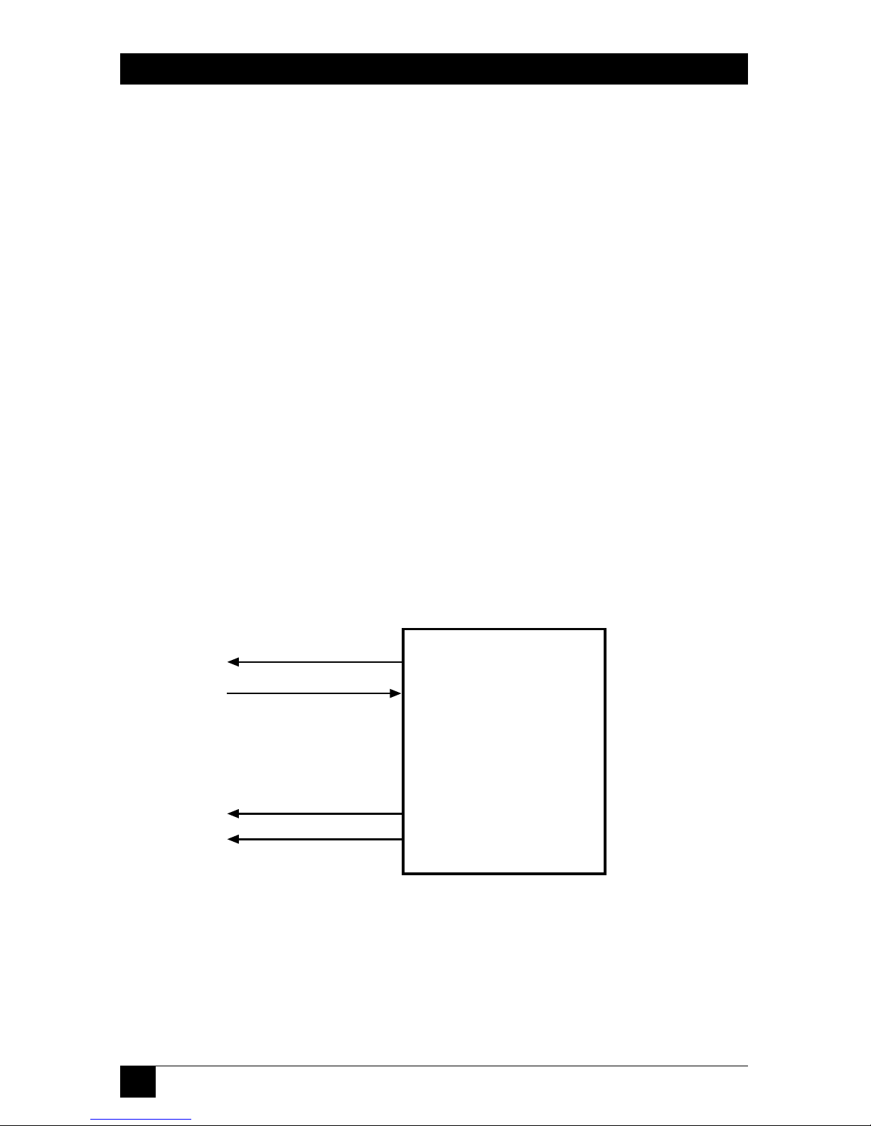
• DCE—the interface module supplies clock signals for the receive and transmit
paths. For the X.21 interface, the module provides only a transmit clock signal,
and expects to receive data from the DTE at the same rate. Figure 2-1 shows
the flow of timing signals for the DCE mode.
Figure 2-1. Flow of timing signals for DCE mode.
Interface Module
(DCE Mode)
Transmit Clock
Transmit Data
Receive Data
Receive Clock
RD
RC
TD
TC
13
CHAPTER 2: Introduction
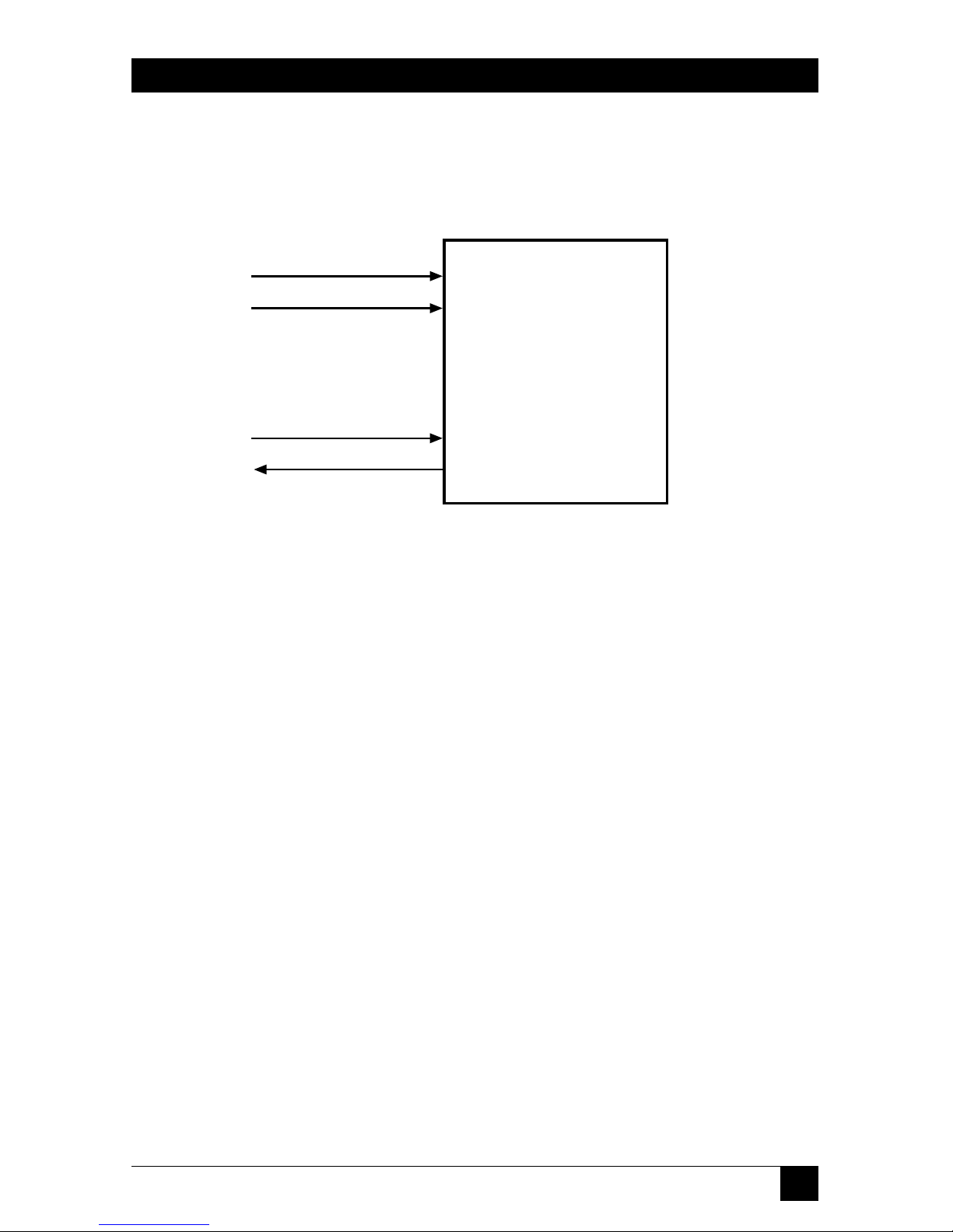
• DTE—the interface module accepts clock signals for the receive and transmit
paths. Note that for the X.21 interface, the module has only a receive clock
input. Figure 2-2 shows the flow of timing signals for the DTE mode.
Figure 2-2. Flow of timing signals for DTE mode.
Interface Module
(DTE Mode)
Transmit Clock
Transmit Data
Receive Data
Receive Clock
RD
RC
TD
TC
14
MODULAR MODEM ELIMINATOR
2.2.5 ITU G.703 64-
KBPS
CO-
DIRECTIONALINTERFACEMODULE
(ME266C)
The 64-kbps co-directional interface specified by ITU G.703 includes only one
transmit pair and one receive pair. To avoid the need for additional pairs, the line
signal waveform specified by G.703 for the 64-kbps co-directional interface includes
timing and framing information.
By using appropriate signal-processing circuits, it is possible to recover
the original data and clock signals from the received signal.
Thus, the receive path of the G.703 64-kbps co-directional internal module
always operates on the clock signal recovered from the received line signal. The
clock signal used by the module transmit path can be selected by means of a
jumper.
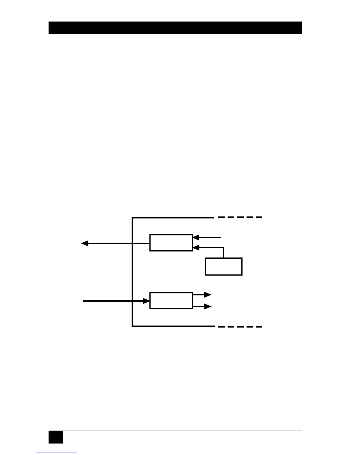
The jumper has two positions:
• INT—the transmit clock is derived from an internal oscillator.
Figure 2-3 shows the flow of timing signals with internal timing.
Figure 2-3. Flow of timing signals for INT mode.
Transmit
Circuits
Transmit
Line Signal
Receive
Line Signal
Receive
Circuits
Internal
Source
Interface
Module
(Int Mode)
Data
Data
Clock
Recovered Clock
 Loading...