

Page 1
MARCH 1998
ME001A
ME001A-E
RS-232 Line Booster
CUSTOMER SUPPORT INFORMATION
Order toll-free in the U.S. 24 hours, 7 A.M. Monday to midnight Friday: 877-877-BBOX
FREE technical support, 24 hours a day, 7 days a week: Call 724-746-5500 or fax 724-746-0746
Mail order: Black Box Corporation, 1000 Park Drive, Lawrence, PA 15055-1018
Web site: www.blackbox.com • E-mail: info@blackbox.com
SERIAL CABLE BOOSTER
1
9
10
15
17
20
21
22
24
EXTERNAL POWER
2
3
4
5
6
7
8
TX CLK (DCE)
SQ
RI
TX CLK (DTE)
-V (9-15VDC)
RX CLK
DTR
CHASSIS GROUND
TX DATA
RX DATA
RTS
CTS
DSR
SIGNAL GROUND
CD
+V (9-15VDC)
24
22
21
20
17
15
10
1
2
3
4
5
6
7
8
9
Page 2

2
RS-232 LINE BOOSTER
FEDERAL COMMUNICATIONS COMMISSION
RADIO FREQUENCY INTERFERENCE STATEMENT
This equipment generates, uses, and can radiate radio frequency
energy and if not installed an used properly, that is, in strict
accordance with the manufacturer's instructions, may cause
interference to radio communication. It has been tested and
found to comply with the limits for a Class A computing device
in accordance with the specifications in Subpart J of Part 15 of
FCC Rules, which are designed to provide reasonable protection
against such interference when the equipment is operated in a
commercial environment. Operation of this equipment in a
residential area is likely to cause interference, in which case
the user at his own expense will be required to take whatever
measures may be required to correct the interference.
Changes or modifications not expressly approved by the party
responsible for compliance could void the user's authority to
operate the equipment.
This digital apparatus does not exceed the Class A limits for Radio
noise emission from digital apparatus set out in the Radio Interference
Regulation of Industry Canada.
Le présent appareil numérique n'émet pas de bruits radioélectriques
dépassant les limites applicables aux appareils numériques de la classe A
prescrites dans le Règlement sur le brouillage radioélectrique édicté par
Industrie Canada.
Page 3

3
RS-232 LINE BOOSTER
Contents
1. Specifications .................................................4
2. Introduction...................................................5
3. Installation......................................................8
Page 4

4
RS-232 LINE BOOSTER
1. Specifications
Protocol — Asynchronous/synchronous
Speed — Transparent
Operation — Transparent
Interface — RS-232/CCITT V.24
Connectors — (1) male DB25P connects to DCE;
(1) female DB25S connects to DTE
Power — ME001A: 120 VAC ± 10%, 60 Hz,
18 watts;
ME001A-E: 100–240 VAC,
50–60 Hz, 0.2A
Size — 1.1"H x 3.5"W x 4.5"D
(2.8 x 8.9 x 11.4 cm)
Weight — 0.4 lb. (0.2 kg)
Page 5

5
RS-232 LINE BOOSTER
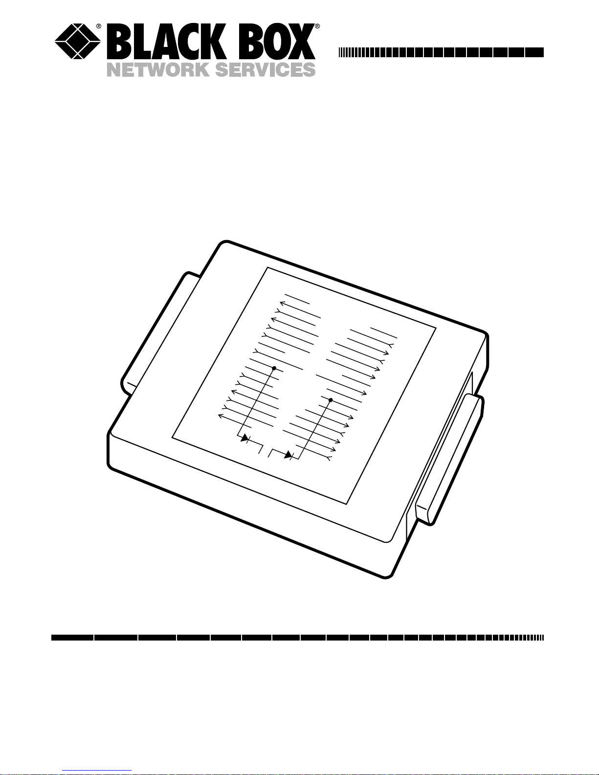
2. Introduction
The RS-232 Line Booster doubles the length of an
RS-232 cable by actively receiving and re-transmitting
twelve of the most common signal lines of the RS232-C
interface. The RS232-C specifications state that the
maximum cable length is limited to 50 feet. In actual
operation (depending on environmental conditions),
you may be able to operate with as much as 100-150
feet of cable. The Line Booster doubles the maximum
cable length if the environmental conditions are
similar over the entire cable and the Booster is in
the center of the cable length.
Under these same conditions, the signal to noise
ratio is halved when using the Line Booster. The
unit is data and data format transparent. It can be
powered from the interface (Pins 9 and 10) or from
its detachable power supply. The lines supported and
the direction of the signal flow are summarized in
Figure 2-1.
Page 6

6
RS-232 LINE BOOSTER
The Line Booster has one DIP switch. At this time,
the DIP switch has no function—it is for future
enhancements.
1 Chassis Gnd. 1
2 TX Data 2
3 RX Data 3
4 RTS 4
5 CTS 5
6 DSR 6
7 Sig. Gnd 7
8CD 8
9 +V (9-15 VDC) 9
10 -V (9-15 VDC) 10
15 TX Clk (DCE) 15
17 RX Clk 17
20 DTR 20
21 SQ 21
22 RI 22
24 TX Clk (DTE) 24
DB25P DB25S
Male Female
External Power
Page 7

7
RS-232 LINE BOOSTER
The Line booster has a male (to DCE) and female
(from DTE) connector with bulkhead (female
screwlock) hardware. If either of the devices being
interconnected has 100 mA of test power on Pins 9
and 10, the unit can be powered from the interface.
If not, a detachable wallmount power supply is
provided and the installation must provide for AC
power to the power supply. The female connector
must be connected to the cable attached to the
equipment sending data to the DCE on Pin 2.
Page 8

8
RS-232 LINE BOOSTER
3. Installation
Connect the cable from your modem (or other DCE
device) to the DCE side of the Line Booster. Connect
the cable from your computer, terminal or printer
(or other DTE device) to the DTE side of the Line
Booster.
Page 9

1000 Park Drive • Lawrence, PA 15055-1018 • 724-746-5500 • Fax 724-746-0746
©Copyright 1998. Black Box Corporation. All rights reserved.
 Loading...