

Black Box ME0008A-ME1, ME0008A-ME1-48, ME0008A-MT1-48, ME0008A-MT1, ME0008A-MCAMP User Manual
...Page 1
CUSTOMER
SUPPORT
INFORMATION
Order toll-free in the U.S.: Call 877-877-BBOX (outside U.S. call 724-746-5500)
FREE technical support 24 hours a day, 7 days a week: Call 724-746-5500 or fax 724-746-0746
Mailing address: Black Box Corporation, 1000 Park Drive, Lawrence, PA 15055-1018
Web site: www.blackbox.com • E-mail: info@blackbox.com
NOVEMBER 2001
ME0008A-ME1
ME0008A-ME1-48
ME0008A-MT1
ME0008A-MT1-48
ME0008A-MCAMP
ME0008A-MCAMP-48
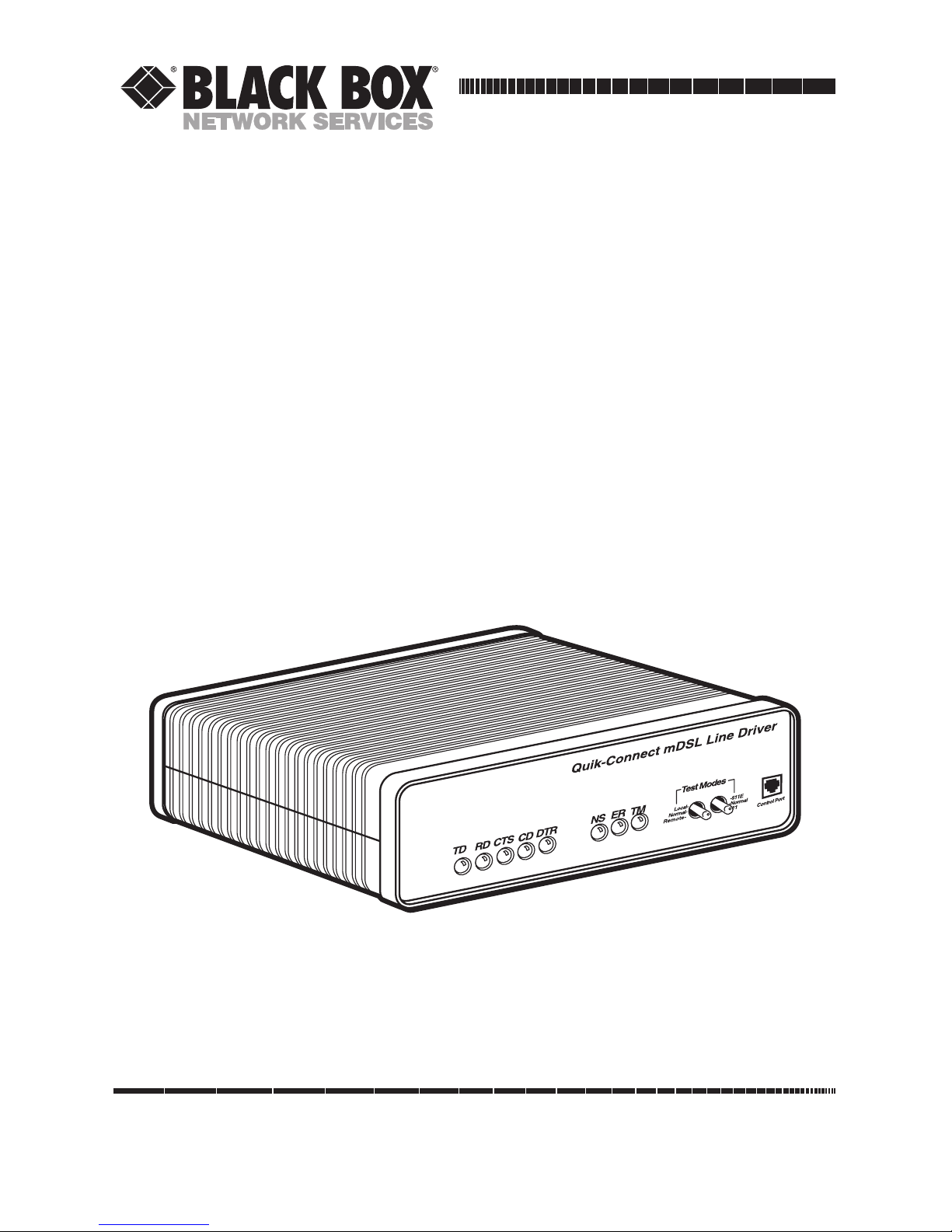
QuikConnect mDSL Line Driver
Page 2

1
FCC AND IC RFI STATEMENTS/CE NOTICE
FEDERAL COMMUNICATIONS COMMISSION
AND
INDUSTRY CANADA
RADIO FREQUENCY INTERFERENCE STATEMENTS
This equipment generates, uses, and can radiate radio frequency energy and if not
installed and used properly, that is, in strict accordance with the manufacturer’s
instructions, may cause interference to radio communication. It has been tested
and found to comply with the limits for a Class A computing device in accordance
with the specifications in Subpart B of Part 15 of FCC rules, which are designed to
provide reasonable protection against such interference when the equipment is
operated in a commercial environment. Operation of this equipment in a
residential area is likely to cause interference, in which case the user at his own
expense will be required to take whatever measures may be necessary to correct
the interference.
Changes or modifications not expressly approved by the party responsible
for compliance could void the user’s authority to operate the equipment.
This digital apparatus does not exceed the Class A limits for radio noise emission from
digital apparatus set out in the Radio Interference Regulation of Industry Canada.
Le présent appareil numérique n’émet pas de bruits radioélectriques dépassant les limites
applicables aux appareils numériques de la classe A prescrites dans le Règlement sur le
brouillage radioélectrique publié par Industrie Canada.
EUROPEAN UNION DECLARATION OF CONFORMITY
This equipment complies with the requirements of the European EMC Directive
89/336/EEC.
Page 3

2
QUIKCONNECT MDSL LINE DRIVER
NORMAS OFICIALES MEXICANAS (NOM)
ELECTRICAL SAFETY STATEMENT
INSTRUCCIONES DE SEGURIDAD
1. Todas las instrucciones de seguridad y operación deberán ser leídas antes de
que el aparato eléctrico sea operado.
2. Las instrucciones de seguridad y operación deberán ser guardadas para
referencia futura.
3. Todas las advertencias en el aparato eléctrico y en sus instrucciones de
operación deben ser respetadas.
4. Todas las instrucciones de operación y uso deben ser seguidas.
5. El aparato eléctrico no deberá ser usado cerca del agua—por ejemplo, cerca
de la tina de baño, lavabo, sótano mojado o cerca de una alberca, etc..
6. El aparato eléctrico debe ser usado únicamente con carritos o pedestales que
sean recomendados por el fabricante.
7. El aparato eléctrico debe ser montado a la pared o al techo sólo como sea
recomendado por el fabricante.
8. Servicio—El usuario no debe intentar dar servicio al equipo eléctrico más allá
a lo descrito en las instrucciones de operación. Todo otro servicio deberá ser
referido a personal de servicio calificado.
9. El aparato eléctrico debe ser situado de tal manera que su posición no
interfiera su uso. La colocación del aparato eléctrico sobre una cama, sofá,
alfombra o superficie similar puede bloquea la ventilación, no se debe colocar
en libreros o gabinetes que impidan el flujo de aire por los orificios de
ventilación.
10. El equipo eléctrico deber ser situado fuera del alcance de fuentes de calor
como radiadores, registros de calor, estufas u otros aparatos (incluyendo
amplificadores) que producen calor.
Page 4

3
NOM STATEMENT
11. El aparato eléctrico deberá ser connectado a una fuente de poder sólo del
tipo descrito en el instructivo de operación, o como se indique en el aparato.
12. Precaución debe ser tomada de tal manera que la tierra fisica y la polarización
del equipo no sea eliminada.
13. Los cables de la fuente de poder deben ser guiados de tal manera que no
sean pisados ni pellizcados por objetos colocados sobre o contra ellos,
poniendo particular atención a los contactos y receptáculos donde salen del
aparato.
14. El equipo eléctrico debe ser limpiado únicamente de acuerdo a las
recomendaciones del fabricante.
15. En caso de existir, una antena externa deberá ser localizada lejos de las lineas
de energia.
16. El cable de corriente deberá ser desconectado del cuando el equipo no sea
usado por un largo periodo de tiempo.
17. Cuidado debe ser tomado de tal manera que objectos liquidos no sean
derramados sobre la cubierta u orificios de ventilación.
18. Servicio por personal calificado deberá ser provisto cuando:
A: El cable de poder o el contacto ha sido dañado; u
B: Objectos han caído o líquido ha sido derramado dentro del aparato; o
C: El aparato ha sido expuesto a la lluvia; o
D: El aparato parece no operar normalmente o muestra un cambio en su
desempeño; o
E: El aparato ha sido tirado o su cubierta ha sido dañada.
Page 5

4
QUIKCONNECT MDSL LINE DRIVER
TRADEMARKS USED IN THIS MANUAL
Any trademarks mentioned in this manual are acknowledged to be the property of the
trademark owners.
Page 6

5
Contents
Chapter Page
1. Specifications . . . . . . . . . . . . . . . . . . . . . . . . . . . . . . . . . . . . . . . . . . . . . . . . . . . . 7
2. Introduction. . . . . . . . . . . . . . . . . . . . . . . . . . . . . . . . . . . . . . . . . . . . . . . . . . . . . 9
2.1 Description. . . . . . . . . . . . . . . . . . . . . . . . . . . . . . . . . . . . . . . . . . . . . . . . . . . 9
2.2 Features . . . . . . . . . . . . . . . . . . . . . . . . . . . . . . . . . . . . . . . . . . . . . . . . . . . . . 9
3. Configuration. . . . . . . . . . . . . . . . . . . . . . . . . . . . . . . . . . . . . . . . . . . . . . . . . . . 11
3.1 Configuring the Hardware DIP Switches. . . . . . . . . . . . . . . . . . . . . . . . . . 11
3.1.1 DIP-Switch S1 . . . . . . . . . . . . . . . . . . . . . . . . . . . . . . . . . . . . . . . . . . 12
3.1.2 DIP-Switch S2 . . . . . . . . . . . . . . . . . . . . . . . . . . . . . . . . . . . . . . . . . . 12
3.1.3 DIP-Switch S3 . . . . . . . . . . . . . . . . . . . . . . . . . . . . . . . . . . . . . . . . . . 14
3.2 Configuring the Software Switches. . . . . . . . . . . . . . . . . . . . . . . . . . . . . . . 17
3.2.1 Monitor . . . . . . . . . . . . . . . . . . . . . . . . . . . . . . . . . . . . . . . . . . . . . . . 17
3.2.2 Configuration . . . . . . . . . . . . . . . . . . . . . . . . . . . . . . . . . . . . . . . . . . 17
3.2.3 VT100 Terminal Setup . . . . . . . . . . . . . . . . . . . . . . . . . . . . . . . . . . . 17
3.3 VT100 Terminal Configuration . . . . . . . . . . . . . . . . . . . . . . . . . . . . . . . . . 18
3.3.1 Main Menu Screen . . . . . . . . . . . . . . . . . . . . . . . . . . . . . . . . . . . . . . 18
3.3.2 Software Configuration Menu . . . . . . . . . . . . . . . . . . . . . . . . . . . . . 19
3.3.3 Option #1: DTE Rate . . . . . . . . . . . . . . . . . . . . . . . . . . . . . . . . . . . . 20
3.3.4 Option #2: Clock Mode Selection Menu . . . . . . . . . . . . . . . . . . . . 21
3.3.5 Option #3: DTE Interface Type. . . . . . . . . . . . . . . . . . . . . . . . . . . . 21
3.3.6 Option #4: DTE Loopback Requests. . . . . . . . . . . . . . . . . . . . . . . . 22
3.3.7 Option #5: Transmit Data Sampling Point . . . . . . . . . . . . . . . . . . . 22
3.3.8 Option #6: CO/CP Mode. . . . . . . . . . . . . . . . . . . . . . . . . . . . . . . . . 23
3.3.9 Option #7: Change Password. . . . . . . . . . . . . . . . . . . . . . . . . . . . . . 23
3.3.10 Exiting the Configuration Mode . . . . . . . . . . . . . . . . . . . . . . . . . . . 23
3.4 Plug-and-Play . . . . . . . . . . . . . . . . . . . . . . . . . . . . . . . . . . . . . . . . . . . . . . . . 24
4. Installation . . . . . . . . . . . . . . . . . . . . . . . . . . . . . . . . . . . . . . . . . . . . . . . . . . . . . 26
4.1 Connecting the Twisted-Pair Interface . . . . . . . . . . . . . . . . . . . . . . . . . . . 26
4.2 Connecting the Serial Port . . . . . . . . . . . . . . . . . . . . . . . . . . . . . . . . . . . . . 27
4.2.1 Changing QuikConnect Modules . . . . . . . . . . . . . . . . . . . . . . . . . . 27
4.2.2 Connecting to a DTE Device . . . . . . . . . . . . . . . . . . . . . . . . . . . . . . 28
4.2.3 Connecting to a DCE Device . . . . . . . . . . . . . . . . . . . . . . . . . . . . . . 28
4.2.4 Configuring the X.21 QuikConnect Module . . . . . . . . . . . . . . . . . 29
4.3 Connecting Power . . . . . . . . . . . . . . . . . . . . . . . . . . . . . . . . . . . . . . . . . . . . 29
4.3.1 Connecting to an AC Power Source . . . . . . . . . . . . . . . . . . . . . . . . 29
4.3.2 Connecting to a DC Power Source . . . . . . . . . . . . . . . . . . . . . . . . . . 30
CONTENTS
Page 7

6
QUIKCONNECT MDSL LINE DRIVER
Chapter Page
5. Operation. . . . . . . . . . . . . . . . . . . . . . . . . . . . . . . . . . . . . . . . . . . . . . . . . . . . . . 31
5.1 Power-Up . . . . . . . . . . . . . . . . . . . . . . . . . . . . . . . . . . . . . . . . . . . . . . . . . . . 31
5.2 LED Status Indicators . . . . . . . . . . . . . . . . . . . . . . . . . . . . . . . . . . . . . . . . . 31
5.3 Test Modes . . . . . . . . . . . . . . . . . . . . . . . . . . . . . . . . . . . . . . . . . . . . . . . . . . 32
5.3.1 Overview . . . . . . . . . . . . . . . . . . . . . . . . . . . . . . . . . . . . . . . . . . . . . . 32
5.3.2 Restart Procedure and Timeouts. . . . . . . . . . . . . . . . . . . . . . . . . . . 33
5.3.3 Loops and Patterns . . . . . . . . . . . . . . . . . . . . . . . . . . . . . . . . . . . . . . 34
5.3.4 Using the V.52 (BER) Test-Pattern Generator. . . . . . . . . . . . . . . . 39
Appendix A. Interface Pin Assignments . . . . . . . . . . . . . . . . . . . . . . . . . . . . . . . 40
Appendix B. Distance Tables . . . . . . . . . . . . . . . . . . . . . . . . . . . . . . . . . . . . . . . . 45
Appendix C. Control Port Pinout . . . . . . . . . . . . . . . . . . . . . . . . . . . . . . . . . . . . 46
Page 8

7
CHAPTER 1: Specifications
1. Specifications
Transmission Format: Synchronous
Transmission Line: Two-wire unconditioned twisted pair
Clocking: Internal, external, or receive recovered
Interface Modules: EIA RS-232/ITU/T V.24, RS-232/530, ITU V.35, ITU/T X.21,
10BASE-T Ethernet, G.703/G.704
Line Rates:
ME0008A-MT1 and ME0008A-MT1-48: 144, 272, 400, 528, 784, 1040, and 1552
kbps;
ME0008A-ME1 and ME0008A-ME1-48: 144, 272, 400, 528, 784, 1040, 1552, and
2064 kbps;
ME0008A-MCAMP and ME0008A-MCAMP-48: 144, 272, 400, 528, 784, 1040, 1552,
2064, and 2320 kbps
DTE Rates:
ME0008A-MT1 and ME0008A-MT1-48: 64, 128, 192, 256, 320, 384, 448, 512, 576,
640, 704, 768, 832, 896, 960, 1024, 1088, 1152, 1216, 1280, 1344, 1408, 1472 and
1536 kbps;
ME0008A-ME1 and ME0008A-ME1-48: 64, 128, 192, 256, 320, 384, 448, 512, 576,
640, 704, 768, 832, 896, 960, 1024, 1088, 1152, 1216, 1280, 1344, 1408, 1472, 1536,
1600, 1664, 1728, 1792, 1856, 1920, 1984, and 2048 kbps;
ME0008A-MCAMP and ME0008A-MCAMP-48: 64, 128, 192, 256, 320, 384, 448, 512,
576, 640, 704, 768, 832, 896, 960, 1024, 1088, 1152, 1216, 1280, 1344, 1408, 1472,
1536, 1600, 1664, 1728, 1792, 1856, 1920, 1984, 2048, 2112, 2176, 2240, and 2304
kbps
Diagnostics: V.52-compliant bit error rate pattern (511/511E pattern) generator
and detector with error injection mode; Local Line Loopback and Remote Digital
Loopback, activated by front-panel switch or via serial interface
Indicators: LEDs: TD, RD, CTS, CD, DTR, NS (no signal), ER (error), and TM
(test mode)
Page 9

8
QUIKCONNECT MDSL LINE DRIVER
Connectors: All units: RJ-45 on line side; RJ-45 on front of unit (control port);
DB25 female, M/34 female, DB15 female, RJ-45 female, or dual BNC on serial
interface side, depending upon which interface module is installed
Temperature Tolerance: 32 to 122°F (0 to 50°C)
Humidity: 5 to 95% noncondensing
Power: ME0008A-ME1, ME0008A-MT1, ME0008A-MCAMP: 100 to 240 VAC, 50 to
60 Hz (universal input), 10 watts; ME0008A-ME1-48, ME0008A-MT1-48,
ME0008A-MCAMP-48: -40 to -60 VDC
Size: 1.6"H x 7.3"W x 6.6"D (4.1 x 18.5 x 16.8 cm)
Weight: 2 lb. (1 kg)
Page 10

9
CHAPTER 2: Introduction
2. Introduction
2.1 Description
The QuikConnect mDSL Line Driver provides high-speed 2-wire connectivity to
ISPs, PTTs, and corporations using mDSL (Multi-rate Digital Subscriber Line)
technology. Multi-rate DSL has the ability to deliver the maximum bit rate that a
twisted-pair line can accommodate. Supporting multiple line rates from 144 kbps
to 2.320 Mbps, the QuikConnect provides “megabyte” speeds to leased-line, LANto-LAN interconnection, and WAN access networks over 3.6 miles/5.8 km
(1.054 Mbps on 24-AWG/0.5-mm wire).
The QuikConnect mDSL Line Driver standalone allows DTE speeds from 64 kbps
to 2.3 Mbps in 64-kbps increments. Features include loopback diagnostics, inband
SNMP/HTTP remote management capabilities, and externally accessible
configuration switches.
As a symmetric DSL NTU, the QuikConnect offers the same data rates in both
directions over a single pair of regular telephone lines using Carrierless Amplitude
and Phase (CAP) modulation. Featuring replaceable DCE-DTE interface modules,
the QuikConnect can be configured for a huge range of V.24/RS-232, V.35,
RS-422/530, G.703, and X.21 applications. Line connection is made by an RJ-45
jack. The standard QuikConnect mDSL Line Driver is powered by a 100- to 240VAC universal power supply. The DC power supply option supports any DC input
between -40 and -60 VDC.
The plug-and-play feature allows you to configure the DTE rate for the link from
the mDSL Rack Card (ME0003C) at the central office. The standalone unit
(ME0008A) at the customer premise site will automatically configure itself to the
DTE rate of the rack card. Other configuration parameters fall to the default state.
This lets you handle configuration changes from a single end of the link.
2.2 Features
• DSL distances on just two wires using mDSL technology.
• DTE speeds n x 64 to 1.152 Mbps.
• 2-wire operation.
• Plug-and-play master or slave.
Page 11

10
QUIKCONNECT MDSL LINE DRIVER
• SNMP network management with in-band management of remote units plus
advanced diagnostics and statistics using an Managed Micro Rack
SNMP/HTTP Card (part number RM261C-SNMP).
• Internal, external, or receive recovered clocking options.
• LED indicators for TD, RD, CTS, CD, DTR, TM, ER, and NS.
Page 12

11
CHAPTER 3: Configuration
3. Configuration
The QuikConnect mDSL Line Driver is equipped with three sets of eight DIP
switches. This chapter describes switch locations and explains all possible
configurations.
3.1 Configuring the Hardware DIP Switches
The 24 external switches are grouped into three eight-switch sets, and are
externally accessible from the underside of the QuikConnect (see Figure 3-1).
Figure 3-1. Underside of the QuikConnect,
showing the location of the DIP switches.
The three sets of DIP switches on the underside of the QuikConnect will be
referred to as S1, S2, and S3. As Figure 3-2 shows, the orientation of all DIP
switches is the same with respect to ON and OFF positions.
Figure 3-2. Close-up of configuration switches
(all sets are identical in appearance).
Back
Front
Page 13
12
QUIKCONNECT MDSL LINE DRIVER
3.1.1 DIP-S
WITCH
S1
All switches in Switch S1 are reserved for future use. These switches should remain
in the ON position.
3.1.2 DIP-S
WITCH
S2
The configuration switches on S2 allow you to specify the clocking mode and
response to DTE loop enable. Default settings of S2 are shown in Table 3-1.
Table 3-1. S2 summary.
Position Function Factory Default
S2-1 Reserved Off
S2-2 Reserved Off
S2-3 Reserved Off
S2-4 Reserved Off
S2-5 Reserved Off
S2-6 Clock Mode On
S2-7 Clock Mode Off
S2-8 Enable Loop from DTE Off Disable
Switches S2-1, S2-2, S2-3, S2-4, and S-5
These switches are reserved for future use and should remain in the OFF position.
}
Receive
Recovered Clock
Page 14

13
CHAPTER 3: Configuration
Switches S2-6 and S2-7: Clock Mode
Use Switches S2-6 and S2-7 to configure the QuikConnect for internal, external, or
receive recover clock mode.
Table 3-2. Clock mode.
CO/CP S2-6 S2-7 Clock Mode Description
Unit
CO On On Internal Transmit clock
generated internally
CO Off On External (DTE) Transmit clock
derived from terminal
interface
CP On Off Receive Transmit clock
Recover derived from the
received line
Off Off Reserved
Switch S2-8: Enable/Disable Loop Tests from DTE
Use Switch S2-8 to allow the QuikConnect to enter loopback tests when the DTE
raises the appropriate loop request pin.
Table 3-3. Enable/disable loop tests.
S2-8 Setting
On Response to DTE loopback request enabled
Off Response to DTE loopback request disabled
Page 15

14
QUIKCONNECT MDSL LINE DRIVER
3.1.3 DIP-S
WITCH
S3
Use the eight DIP switches in Switch S3 to enable the DTE connection rate. Table
3-4 summarizes default positions of DIP-switch S3. Detailed descriptions of each
switch follow the table.
Table 3-4. S3 summary.
Position Function Factory Default
S3-1 DTE Rate On
S3-2 DTE Rate Off
S3-3 DTE Rate Off
S3-4 DTE Rate Off
S3-5 DTE Rate On
S3-6 DTE Rate On
S3-7 Reset Software Defaults On Normal Operation
S3-8 Transmit Data Sample Point On Normal Operation
Switches S3-1 through S3-6: DTE Rate
Table 3-5. DTE bit rate.
S3-1 S3-2 S3-3 S3-4 S3-5 S3-6 DTE Rate (kbps)
Off Off On On On On 64
On On Off On On On 128
Off On Off On On On 192
On Off Off On On On 256
Off Off Off On On On 320
On On On Off On On 384
Off On On Off On On 448
On Off On Off On On 512
Off Off On Off On On 576
On On Off Off On On 640
Off On Off Off On On 704
On Off Off Off On On 768
Off Off Off Off On On 832
}
768 kbps
Page 16

15
CHAPTER 3: Configuration
Table 3-5 (continued). DTE bit rate.
S3-1 S3-2 S3-3 S3-4 S3-5 S3-6 DTE Rate (kbps)
On On On On Off On 896
OffOnOnOnOffOn 960
On Off On On Off On 1024
Off Off On On Off On 1088
On On Off On Off On 1216
On Off Off On Off On 1280
Off Off Off On Off On 1344
On On On Off Off On 1408
Off On On Off Off On 1472
On Off On Off Off On 1536
On On Off Off Off On 1600
Off On Off Off Off On 1664
On Off Off Off Off On 1728
Off Off Off Off Off On 1792
On On On On On Off 1856
Off On On On On Off 1920
On Off On On On Off 1984
Off Off On On On Off 2048
On On Off On On Off 2112
Off On Off On On Off 2176
On Off Off On On Off 2240
Off Off Off On On Off 2304
NOTE
The actual line rate of the QuikConnect is determined by the selection of
the DTE rate. To see the line rate associated with various DTE rates,
refer to the distance chart in Appendix B.
Page 17

16
QUIKCONNECT MDSL LINE DRIVER
Switch S3-7: Reset Software Defaults
Switch S3-7 allows you to reset the software-configured factory defaults. This will
only be needed when using the Managed Micro Rack SNMP/HTTP Card (part
number RM261C-SNMP) to SNMP manage your units. For more information,
please refer to the Managed Micro Rack SNMP/HTTP Card Users’ Manual.
Table 3-6. Reset software defaults.
S3-7 Setting
On Normal Operation
Off Reset
Switch S3-8: Transmit Data (TD) Sampling Point
Table 3-7. Transmit data sampling point.
S3-8 Setting Description
On Normal TD sampled on the falling edge of the
QuikConnect Transmit Clock (TC)
Off Invert TD sampled on the rising edge of the
QuikConnect Transmit Clock
Page 18

17
CHAPTER 3: Configuration
3.2 Configuring the Software Switches
The QuikConnect mDSL Line Driver features a menu-driven command system that
allows you to monitor and configure your mDSL Line Driver. There are two modes
of operation for the Line Driver’s control port: Monitor and Configuration. These
are described in more detail in the sections that follow. After the setup instructions
for the mDSL Line Driver (Sections 3.2.1 and 3.2.2) is a description of how to
setup your VT100 (or equivalent) control port for use with the mDSL Line Driver.
3.2.1 M
ONITOR
If you are configuring your mDSL Line Driver through the DIP switches and you
want to check your configuration or view the status of the Line Driver, you can do
so by accessing the control port. In this setup, you are not able to make
configuration changes to the Line Driver because the hardware DIP-switch settings
are controlling the configuration of the Line Driver. If you would like to use the
control port to configure your Line Driver, see Section 3.2.2.
3.2.2 C
ONFIGURATION
If you would like to use the Line Driver’s control port to configure your unit, you
must set all of the DIP switches to the ON position. This will force the Line Driver
into the plug-and-play mode. (This configuration is also required if you intend to
have the Line Driver work in a plug-and-play environment or use the Managed
Micro Rack SNMP/HTTP Card [part number RM261C-SNMP] to configure the
unit.)
3.2.3 VT100 T
ERMINALSETUP
1. Connect the serial RS-232 port of a VT100™ or similar DTE with terminal
emulation to the control port of the Line Driver. To construct an RS-232 to
EIA-561 patch cable, refer to the control port pinout diagram in Appendix C.
2. Power up the terminal and set the RS-232 port as follows:
9600 baud
8 data bits, 1 stop bit, no parity
Local echo
CR-CR/LF on inbound data
ANSI, VT100 emulation
3. Power up the Line Driver.
4. After the Line Driver is powered on, the control port will display the Main
menu screen. If the Main menu isn’t shown, please review your VT100 setup
as described above.
Page 19

18
QUIKCONNECT MDSL LINE DRIVER
3.3 VT100 Terminal Configuration
You can configure the Line Driver using a VT100 compatible terminal (or
program). With the VT100 interface, you can perform all functions available via
the DIP switches. The VT100 operation is available from the Main menu page.
3.3.1 M
AINMENUSCREEN
The Main menu screen for the Line Driver is displayed in Figure 3-3. You can press
Esc to refresh this screen at any time. If you are running in the Monitor mode, the
Line Driver will not require a password. If you want to run in the Configuration
mode, you will be required to enter a password to access to configuration menus.
The default password shipped with the Line Driver is “blackbox” (all lower case).
The Line Driver is case-sensitive and will not work if the correct password is not
installed. If an incorrect password is entered, you will receive an error message and
be prompted for the password again. We suggest that you change your password
after setting up your Line Driver to ensure security for your network.
Figure 3-3. Main menu.
VT100 Software Configuration
Black Box Corporation Copyright (c) 2001
Software version x.xx.xx
Active Configuration: Plug-and-play mode
DTE Rate: 2304 kbps
Clock Mode: Receive Recover Clock
DTE Interface Type: Normal Mode
DTE Loopback: Disable
Transmit Data Sampling Point: Normal
Connection Status: Data Mode
CD (Carrier Detect): Active
CTS (Clear to Send): Active
DSR (Data Set Ready): Active
RTS (Request to Send): Inactive
DTR (Data Terminal Ready): Inactive
Press Esc to Refresh screen
Please Enter Password:
Page 20

19
CHAPTER 3: Configuration
3.3.2 S
OFTWARECONFIGURATIONMENU
When the correct password is entered, the Software Configuration menu will
appear. Select the option that you would like to change.
NOTE
After making any configuration changes, you are required to select the
“Exit and Save Changes” if you would like the changes to be
implemented into the Line Driver.
The Software Configuration menu is shown in Figure 3-4.
Figure 3-4. Software Configuration menu.
Local Software Configuration Menu
1) DTE Rate
2) Clock Mode
3) DTE Interface Type
4) DTE Loopback
5) Transmit Data Sampling Point
6) CO/CP Mode
7) Change Password
8) Exit Without Saving Changes
9) Exit and Save Changes
Please Enter Your Selection (1–9)
Page 21

20
QUIKCONNECT MDSL LINE DRIVER
3.3.3 O
PTION
#1: DTE R
ATE
If option 1 is selected in the Software Configuration menu, a DTE rate sub-menu
will be displayed to select the DTE rate of the Line Driver. After selecting the
required DTE rate, the Software Configuration menu will appear.
NOTE
The Line Driver is currently set for Plug-and-Play, with all DIP switches
in the ON position. If you are connecting your QuikConnect mDSL Line
Driver to a Managed Micro Rack SNMP/HTTP Card (RM261C-SNMP), the
standalone Line Driver will automatically configure itself for the DTE
rate selected on the mDSL Line Driver Rack Card (ME0003C).
Figure 3-5. DTE Rate Selection menu.
DTE Rate Selection Menu
A) 2304 kbps S) 1152 kbps
B) 2240 kbps T) 1088 kbps
C) 2176 kbps U) 1024 kbps
D) 2112 kbps V) 960 kbps
E) 2048 kbps W) 896 kbps
F) 1984 kbps X) 832 kbps
G) 1920 kbps Y) 768 kbps
H) 1856 kbps Z) 704 kbps
I) 1792 kbps a) 640 kbps
J) 1728 kbps b) 576 kbps
K) 1664 kbps c) 512 kbps
L) 1600 kbps d) 448 kbps
M) 1536 kbps e) 384 kbps
N) 1472 kbps f) 320 kbps
O) 1408 kbps g) 256 kbps
P) 1344 kbps h) 192 kbps
Q) 1280 kbps i) 128 kbps
R) 1216 kbps j) 64 kbps
Please Enter Your Selection (A–j)
Page 22

21
3.3.4 O
PTION
#2: C
LOCKMODE
If option 2 is selected in the Software Configuration menu, the Line Driver will
display the Clock Mode menu. This menu will allow you to set the clock mode for
the mDSL Line Driver standalone unit (ME0007A-mDSL). After making your
selection, the Line Driver will display the Software Configuration menu.
Figure 3-6. Clock Mode selection menu.
3.3.5 O
PTION
#3: DTE I
NTERFACETYPE
If option 3 is selected in the Software Configuration menu, the Line Driver will
display the DTE Interface Type menu. This menu allows you to select the type of
QuikConnect module that is installed in the Line Driver. By default, the Line
Driver is set for serial/Ethernet interface. This selection will cover almost all of the
Black Box QuikConnect modules except the G.703/G.704 QuikConnect module.
If you are using this interface and it supports n x 64 kbps G.704 network extension,
then you should set the interface type for 2) G.703/G.704 interface.
Figure 3-7. DTE Interface Type menu.
DTE Interface Type Selection Menu
1) Serial/Ethernet Interface
2) G.703/G.704 Interface
Please Enter Your Selection: (1–2)
Clock Mode Selection Menu
1) Internal Clock
2) External Clock
3) Receive Recover Clock
Please Enter Your Selection: (1–3)
CHAPTER 3: Configuration
Page 23

22
QUIKCONNECT MDSL LINE DRIVER
3.3.6 O
PTION
#4: DTE L
OOPBACK
If option 4 is selected, the Line Driver will display the DTE Loopback menu. This
menu will allow you to enable or disable loopbacks from the DTE interface. The
DTE Loopback menu is shown in Figure 3-8.
Figure 3-8. DTE Loopback menu.
3.3.7 O
PTION
5: T
RANSMITDATASAMPLINGPOINT
If option 5 is selected, the Line Driver will display the Transmit Data Sampling
Point menu. This menu allows you to set the sampling point for the transmit data
entering the Line Driver from the DTE interface. Under normal conditions, this
variable should be set to normal. The Transmit Data Sampling Point menu is
shown in Figure 3-9.
Figure 3-9. Transmit Data Sampling Point menu.
Transmit Data Sampling Point Selection menu
1) Normal (TD sampled on the falling edge of TC)
2) Invert (TD sampled on the rising edge of TC)
Please Enter Your Selection: (1–2)
DTE Loopback Selection Menu
1) ENABLE Response to DTE Loopback Request
2) DISABLE Response to DTE Loopback Request
Please Enter Your Selection: (1–2)
Page 24

23
CHAPTER 3: Configuration
3.3.8 O
PTION
#6: CO/CP M
ODE
If option 6 is selected, the Line Driver will display the CO/CP Mode menu. This
option is only needed when the Line Driver is using the G.703/G.704 module and
is connected to another DSL line driver using the G.703/G.704 interface module
(ME0005A-G703, ME0004C-G703, etc.). In that particular application, both the
Line Drivers should be set for the external clock mode, and one unit will need to
be forced into the CP mode for the DSL line to function properly.
Figure 3-10. CO/CP Mode menu.
3.3.9 O
PTION
#7: C
HANGEPASSWORD
If option 7 is selected, the Line Driver will request a new password from you. After
you enter the password, the Line Driver will request that you confirm the changes.
Figure 3-11. Change Password screen.
3.3.10 E
XITING THECONFIGURATIONMODE
After making configuration changes, select option 9 (Exit and Save Changes) to
implement the configuration changes. If you do not want the configuration
changes to be implemented, select option 8 (Exit Without Saving Changes).
Please Enter New Password: ********
Confirm Changes (Y/N):
CO/CP Selection Menu
1) Normal
2) Force unit to CP mode
Please Enter Your Selection: (1–2)
Page 25

24
QUIKCONNECT MDSL LINE DRIVER
3.4 Plug-and-Play
The Plug-and-Play application allows ISPs and PTTs to quickly upgrade the link
speed for a customer without re-configuring the customer premise (CP) Line
Driver. It will also allow ISPs and PTTs to set up all of the configurations at the
central office (on the rack cards) before installing the standalone units, saving time
spent configuring and re-configuring DIP-switch settings.
The Plug-and-Play feature allows you to configure the DTE rate for the link from
the rack card at the central office (CO). The standalone unit at the customer
premise (CP) site will automatically configure itself to the DTE rate of the rack
card. Other configuration parameters fall to the default state. This allows changes
in the configuration to be handled from a single end of the link.
When installing a CO/CP style application, the local end of the link is composed of
a CO unit (ME0004C) set to either internal or external clocking mode and a CP
unit (ME0008A) set as a Plug-and-Play CP. The Plug-and-Play standalone will have
all of its DIP switches set to the ON position.
Figure 3-12. Typical Plug-and-Play application.
When the Line Drivers are connected, the CP will come up with a pre-defined
default configuration (receive recovered clocking). During the handshaking
process between the Line Drivers, the CO unit will set the DTE rate/line rate of
the CP unit to match its DIP-switch configuration settings. If the DTE rate for the
link requires a change, the change is needed only at the CO side of the link.
mDSL Rack Card
(ME0004C)
DIP switches configured
according to specific
application requirements.
DIP switches all in
ON position.
QuikConnect
Line Driver
(ME0008A)
Page 26

25
The Plug-and-Play application will also work in the managed system using the
Managed Micro Rack SNMP/HTTP Card (RM261C-SNMP) and mDSL Line Driver
Rack Cards (ME0004C) installed in the Managed Micro Rack (RM260). In this
application, the system administrator can configure the entire rack through the
Network Management Station (NMS) before the standalone (CP) units are
installed. For more information on the SNMP management of your rack, please
refer to the Managed Micro Rack SNMP/HTTP Users’ Manual.
CHAPTER 3: Configuration
Page 27

26
QUIKCONNECT MDSL LINE DRIVER
4. Installation
Once the QuikConnect mDSL Line Driver is properly configured, it is ready to
connect to the twisted-pair interface, to the serial port, and to the power source.
This chapter tells you how to make these connections.
4.1 Connecting the Twisted-Pair Interface
The QuikConnect mDSL Line Driver supports communication between two DTE
devices at distances to 5 miles (8 km) over 24-AWG (0.5-mm) twisted-pair wire.
Two things are essential:
1. These units work in pairs. Both units at the end of the twisted pair must have
the same 2-wire connection and DTE rate.
2. To function properly, the QuikConnect mDSL Line Driver needs one twisted
pair of metallic wire. This twisted pair must be unconditioned, dry, metallic
wire, between 19 (0.9 mm) and 26 AWG (0.4 mm); the higher-number gauges
will limit distance. Standard dial-up telephone circuits, or leased circuits that
run through signal equalization equipment, or standard, flat modular
telephone type cable, are not acceptable.
IMPORTANT!
The QuikConnect mDSL Line Driver has been optimized for performance
at high bit rates (DTE rates greater than 512 kbps). To ensure accurate
performance at these rates, please use twisted-pair line interface cable
that is at least 330 ft. (100 m) long.
The RJ-45 connector on the QuikConnect’s twisted-pair interface is polarity
insensitive and is wired for a two-wire interface. The signal/pin relationships are
shown in Figure 4-1.
Figure 4-1. RJ-45 twisted-pair line interface.
- - - - - - - - - - - - - - - - - - - - - - - - 1 (N/C)
- - - - - - - - - - - - - - - - - - - - - - - - 2 (N/C)
- - - - - - - - - - - - - - - - - - - - - - - - 3 (N/C)
- - - - - - - - - - - - - - - - - - - - - - - - 4 (Tip)
- - - - - - - - - - - - - - - - - - - - - - - - 5 (Ring)
- - - - - - - - - - - - - - - - - - - - - - - - 6 (N/C)
- - - - - - - - - - - - - - - - - - - - - - - - 7 (N/C)
- - - - - - - - - - - - - - - - - - - - - - - - 8 (N/C)
Page 28

27
CHAPTER 4: Installation
4.2 Connecting the Serial Port
The serial port interface on the QuikConnect mDSL Line Driver uses
interchangeable QuikConnect modules. Each QuikConnect module has a 50-pin
card-edge connector on one side and a serial port interface on the other. Figure 33 shows how a QuikConnect module plugs into the back of the QuikConnect
mDSL Line Driver.
Figure 4-2. Installing the plug-in serial interface module.
4.2.1 C
HANGINGQUIKCONNECTMODULES
Your QuikConnect mDSL Line Driver has the appropriate QuikConnect module
already installed. If you need to install a different QuikConnect module, follow
these steps:
Removing the Existing QuikConnect Module
1. Turn the power switch off. Leave the power cord plugged into a grounded
outlet to keep the unit grounded.
2. Loosen the two thumbscrews on the module by turning them counterclockwise.
3. Grasp the two thumbscrews and gently pull the module from the unit. Apply
equal force to the thumbscrews to keep the module straight during the
removal process.
Page 29

28
QUIKCONNECT MDSL LINE DRIVER
Installing the New QuikConnect Module
1. Make sure the power switch is off. Leave the power cord plugged into a
grounded outlet to keep the unit grounded.
2. Hold the module with the faceplate toward you and align the module with
the guide slots in the rear panel of the QuikConnect mDSL Line Driver.
3. While keeping the module’s faceplate parallel with the Line Driver’s rear
panel, slide the module straight in so that the card-edge contacts line up with
the socket inside the chassis.
NOTE
The card-edge connector should meet the socket when it is almost all
the way into the chassis. If you encounter a lot of resistance, remove the
module and repeat steps 2 and 3.
4. With the card-edge contacts aligned with the socket, firmly seat the module by
using your thumbs to apply pressure directly to the right and left edges of the
module faceplate. Applying moderate and even pressure should be sufficient
to seat the module. You should hear it “click” into place.
5. To secure the module in place, push the thumbscrews into the chassis and
turn the screws clockwise to tighten.
4.2.2 C
ONNECTING TO A
DTE D
EVICE
The serial port on most QuikConnect interface modules (all except the X.21
module) is hard-wired as a DCE. Therefore these modules “want” to plug into a
DTE such as a terminal, PC, or host. When making the connection to your DTE
device, use a straight-through cable of the shortest possible length—we
recommend 6 feet (1.8 m) or less. When purchasing or constructing an interface
cable, please refer to the pin diagrams in Appendix A as a guide.
4.2.3 C
ONNECTING TO A
DCE D
EVICE
If the Line Driver’s QuikConnect interface module is hard-wired as a DCE (all
except the X.21 module), you must use a null-modem cable when connecting to a
modem, multiplexor, or other DCE device. This cable should be of the shortest
possible length—we recommend 6 feet (1.8 m) or less. When purchasing or
constructing a null-modem interface cable, use the pin diagrams in Appendix A as
a guide.
Page 30

29
NOTE
Pinout requirements for null-modem applications vary widely between
manufacturers. If you have any questions about a specific application,
call Black Box Technical Support at 724-746-5500.
4.2.4 C
ONFIGURING THE
X.21 Q
UIKCONNECTMODULE
The serial port on the X.21 QuikConnect module is default wired as a DCE, but
may be switched to a DTE. This is done by reversing the orientation of the
DCE/DTE strap, as described below.
To reverse DCE/DTE orientation, remove the module according to the
instructions in Section 4.2.1. The DCE/DTE strap is located on the bottom side of
the module’s PC board. The arrows on the top of the strap indicate the
configuration of the X.21 port (for example, if the DCE arrows are pointing
toward the DB15 connector, the X.21 port is wired as a DCE). Reverse the
DCE/DTE orientation by pulling the strap out of its socket, rotating it 180º, then
plugging the strap back into the socket. You will see that the DCE/DTE arrows now
point in the opposite directions, showing the new configuration of the X.21 port.
Reinstall the module according to the instructions in Section 4.2.1.
4.3 Connecting Power
The QuikConnect mDSL Line Driver comes with a 100- to 240-VAC universal
power supply (part numbers ME0008A-ME1, ME0008A-MT1, and ME0008AMCAMP) or -40- to -60-VDC power supply (part numbers ME0008A-ME1-48,
ME0008A-MT1-48, and ME0008A-MCAMP-48). No re-configuration is required.
The universal interface AC supply is equipped with a male IEC 320 power
connection.
The DC power supply is equipped with a 3-pin “terminal strip” style connector.
4.3.1 C
ONNECTING TO AN
AC P
OWERSOURCE
To connect the standard or universal power supply, follow these steps:
1. Attach the power cord (supplied) to the shrouded male IEC 320 connector
on the rear of the QuikConnect mDSL Line Driver.
2. Plug the power cord into a nearby AC power outlet.
3. Turn the rear power switch ON.
CHAPTER 4: Installation
Page 31

30
QUIKCONNECT MDSL LINE DRIVER
4.3.2 C
ONNECTING TO A
DC P
OWERSOURCE
The -48-VDC power supply option uses a 3-pin terminal block with spring-type
connectors.
WARNING
There are no user-serviceable parts in the power supply section of the
Line Driver. Only qualified service personnel should replace the fuse.
Contact Black Box Technical Support at 724-746-5500 for more
information.
Page 32

31
CHAPTER 5: Operation
5. Operation
Once the QuikConnect mDSL Line Driver is properly configured and installed, it
should operate transparently. This chapter describes power-up, reading the LED
status indicators, and using the built-in loopback test modes.
5.1 Power-Up
To apply power to the QuikConnect, first be sure that you have read Section 4.3.
Then power-up the unit via the rear-panel power switch.
5.2 LED Status Indicators
The QuikConnect mDSL Line Driver features eight front-panel LEDs that monitor
power, the DTE signals, network connection, and test modes. Figure 5-1 shows the
location of each LED. Following Figure 5-1 is a description of each LED’s function.
Figure 5-1. Front panel.
• TD and RD: Glows yellow to indicate an idle condition of Binary “1” data on
the respective terminal interface signals. Green indicates Binary “0” data.
• CTS: Glows green to indicate that the Clear to Send signal from the line driver
is active.
• CD: Glows yellow if no carrier signal is being received from the remote line
driver. Green indicates that the remote line driver’s carrier is being received.
• DTR: Glows green to indicate that the Data Terminal Ready signal from the
terminal is active.
Page 33

32
QUIKCONNECT MDSL LINE DRIVER
• ER: blinks ON/OFF after a 511/511E test has timed out. See Section 5.3.3 for
more information.
ER flashes once to indicate that a CRC error has occurred (during normal
operation) or bit errors have occurred (during 511/511E tests).
Only at power up, ER blinks once every 200 ms if the DTE rate is set to an
unsupported settings.
• TM: glows yellow to indicate that the QuikConnect Line Driver has been
placed in test mode. The unit can be placed in test mode by the local user or
by the remote user.
• NS: (No Signal) glows red to indicate that the local QuikConnect Line Driver
is not connected with the remote QuikConnect Line Driver.
5.3 Test Modes
The QuikConnect mDSL Line Driver offers two proprietary loopback test modes,
plus a built-in V.52 BER test-pattern generator to evaluate the condition of the
modems and the communication link. These tests can be activated physically from
the front panel or via the DTE interface.
5.3.1 O
VERVIEW
Figure 5-2 shows the major elements used in the loopback and pattern tests
available in the Line Driver. Each block has several functions. Following Figure 5-2
are descriptions that show how the elements are used during test modes.
Figure 5-2. The major elements used in the loopback and pattern tests.
Page 34

33
CHAPTER 5: Operation
Framer
The framer is used to determine the status of the line. In normal operation, the
framer transmits and expects to receive framed packets from the far end. If the
framer receives framed packets from the far end, CTS and CD will be active. If
framed packets are not received, CTS and CD will be inactive. The restart
procedure uses this information to determine if a valid connection is made (cable
disconnect, poor cable quality, etc). In normal data mode, if the Line Driver
receives four seconds of unframed packets it will restart and begin trying to reestablish a connection with the far end. The distinction between framed packets
and unframed packets becomes important when we discuss the pattern generator.
Pattern Gen./Det.
This part of the processor generates and detects the 511/511E patterns. When
transmitting 511 patterns, the information is unframed (because it originates after
the framer) and is intended to be evaluated only by another processor. If the units
are in data mode and the pattern generator is enabled on one end of the link, the
far end will begin receiving unframed packets and assume that the line has gone
down. During test modes, we force the pattern generator to time out before it can
cause the link to be killed.
Loop Control
This part of the processor is used to control loopbacks. In a local loop, the data is
looped back towards the local DTE. In a remote loop, the data is looped back to
the line, but it is also allowed to pass through to the framer and to the remote
DTE.
5.3.2 R
ESTARTPROCEDURE ANDTIMEOUTS
The restart procedure is in place to allow the units to re-establish a connection
after the framer begins seeing unframed packets. Table 5-1 shows the amount of
time the framer must see consecutive unframed packets before the unit will restart
and try to establish a new line connection. The reason that there are different
restart times will become apparent after reading the rest of the document. The
511/511E timeout shown refers to the amount of time the 511/511E pattern will
be valid. At the end of this time, the pattern will automatically turn itself off and
the normal data path will be re-established. The ER LED will flash, indicating to
the user that the test has timed out. The ER LED will stop flashing once the
511/511E switch is placed into the normal position.
Page 35

34
QUIKCONNECT MDSL LINE DRIVER
Table 5-1. Test mode timing.
Item Elapsed Time (seconds)
Startup 50
Data Mode 4
511/511E Generator Enabled 60 (The generator will stop after 45
seconds.)
Remote End of an RDL 60
511/511E Timeout 45 (The pattern generator will automatically
turn off after 45 seconds. The ER LED will
flash until you turn off the 511/511E switch.)
Symbol Indicators
This symbol designates the origination or the termination of a data path. The
direction of the arrow connected distinguishes the two data paths.
This symbol designates an invalid data path. If there is data present, it should
be ignored.
5.3.3 L
OOPS ANDPATTERNS
The following section describes the test modes used in the QuikConnect mDSL
Line Driver. At the bottom of each test mode, a figure is included to show the data
path.
Local Loop
There are two different modes of operation for a local loop depending on the
status of the units at the time that the local loop is initiated. If the units are not
linked (NS LED on) and the local loop is initiated, either by the front-panel switch
or the DTE interface, the unit will enter mode 1. If the units are linked, NS LED
off, then the unit will enter a mode 2 local loop.
A mode 1 local loop is shown in Figure 5-3. When the local loop is initiated, either
by the front-panel switch or the DTE interface, the loop will be activated within the
local processor. The data present at the local DTE interface will be looped back to
X
Page 36

35
CHAPTER 5: Operation
the local DTE by the loop control block within the processor. Any data present on
the line or at the far-end DTE interface is invalid. The remote unit will remain in
the startup mode, NS LED on, CTS LED yellow, and CD LED yellow, until the local
unit is taken out of the local loop mode. After the local loop is deselected, the
units will both be in startup mode and the link will be established.
Figure 5-3. Local loop mode 1.
A mode 2 local loop is shown in Figure 5-4. When the local loop is initiated, either
by the front-panel switch or the DTE interface, two separate loop paths will be
started. In the first path, data presented to the local DTE interface will be looped
back to the local DTE within the framer. In the second path, data presented at the
far-end DTE will be transmitted to the local DTE and then looped back within the
local DTE loop control block with the processor. After the local loop is deselected,
the units will be placed back into data mode and the normal data paths will be reestablished.
Figure 5-4. Local loop mode 2.
Page 37

36
QUIKCONNECT MDSL LINE DRIVER
Local Loop with 511/511E
When the unit is placed into a mode 1 local loop and the 511/511E pattern
generator is activated, the local pattern generator begins sending out a 511/511E
pattern to the loop control block. The loop control block will loop this data back
to the 511/511E pattern detector block, which will evaluate the data for errors.
Because the 511/511E pattern generator is contained within the processor, the
data is unframed so the framer will begin seeing unframed packets. The framer
receives this unframed data and cannot distinguish this information from a line
disconnection (this would cause the unit’s restart procedure to start). What we
have done to allow this mode to work is to add timeouts for the pattern generators.
When the 511/511E is initiated, the line-restart procedure is changed to one
minute. The 511/511E pattern will timeout after 45 seconds. So if the 511/511E is
turned on during a local loop, the restart procedure is set to one minute, but the
511/511E pattern will time out after 45 seconds, allowing the framer to begin
seeing framed packets (and not restart the box).
After the 511/511E pattern times out, the ER LED will begin flashing. It will
remain this way until the pattern-generator switch is turned off. Note that the data
at the local DTE and the remote DTE are not valid. Because the data is unframed,
there is no way for the framer to send this data out to the DTE. This is an
important distinction because other units will send out the 511 pattern.
Figure 5-5. Local loop mode 1 with 511/511E.
When the unit is placed into a mode 2 local loop, the 511/511E pattern generator
on the local unit is unavailable for transmission. As can be seen from Figure 5-6,
the 511/511E pattern generator has no data path connections available. The
511/511E pattern generator is still available on the remote unit. For more
information on the proper operation of this pattern generator, please refer to the
Remote Digital Loop with 511/511E section.
Page 38

37
Figure 5-6. Local loop mode 2 with 511/511E.
Remote Digital Loop
The Remote Loop uses the EOC channel (an out-of-band signaling channel) to
establish the remote link. Upon the RDL switch being thrown or DTE initiation, a
RDL_ON Request signal is sent to the remote unit. The remote unit then responds
with an RDL Acknowledge command and the link is established. Data originates at
the local DTE and is looped at the remote processor back to the local DTE. Note
that the data is also passed through to the remote DTE and is not squelched. When
a remote unit enters RDL, it changes its restart timeout to one minute (the reason
will be explained in the RDL with 511/511E section). If the line is disconnected, the
local unit will restart (NS LED activated) after 4–6 seconds, but the remote unit will
wait for one minute before it restarts. Note that the transmit data at the remote
DTE is ignored. When the switch is thrown or the DTE removes the RDL request,
the local unit will transmit an RDL_OFF request to the remote unit. The local unit
will keep its TM LED active until this request has been completely sent out. If the
switch is thrown again before the completion of the termination phase, the switch
will be ignored until it is placed back into the normal position.
Figure 5-7. Remote loop.
CHAPTER 5: Operation
Page 39

38
QUIKCONNECT MDSL LINE DRIVER
Remote Digital Loop with 511/511E
The Remote Digital Loop with 511/511E is shown in Figure 5-8. After RDL is
established, the remote unit’s restart timer is set to one minute. This is done
because when the 511/511E generator is started on the local unit, the remote
framer begins seeing unframed packets. The remote unit cannot distinguish the
511/511E pattern from the line being disconnected, so the restart timer has been
lengthened to allow the pattern generator to function. Once the 511/511E test is
started, the local unit changes its restart timer to one minute. The pattern
originates within the processor and is sent to the remote unit. It is then looped
back to the local unit where it is evaluated for errors. After 45 seconds, the pattern
generator will timeout and stops sending the pattern. The ER LED will begin
blinking until the user turns off the 511/511E switch.
Figure 5-8. Remote loop with 511/511E.
Data Mode with 511/511E Pattern Generators
When the units enter data mode, you can turn on the pattern generators on both
ends of the link. Once a 511/511E pattern is selected on one end of the link, the
pattern generator will begin transmitting unframed 511/511E through the line to
the remote end. A possible problem with this test can occur due to the restart
procedure. Once the local 511/511E is turned on, the remote unit begins
receiving an unframed 511 pattern. If the remote unit does not turn on the
511/511E pattern generator within four seconds, the remote unit will restart and
enter the startup mode. Note that once the 511/511E pattern generator is started,
the restart timer is changed to one minute (only on the unit which has the pattern
enabled). If both units enable the 511/511E pattern within four seconds of each
other, both units will be transmitting and receiving the 511/511E pattern. Both
framers are now receiving unframed data and will restart after one minute. The
511/511E pattern generators will timeout after 45 seconds, re-enabling the normal
data path. The ER LED will begin flashing until the user terminates the test.
Page 40

39
Figure 5-9. Data mode with 511/511E.
5.3.4 U
SING THE
V.52 (BER) T
EST-PATTERNGENERATOR
To use the V.52 BER tests in conjunction with the remote digital loopback tests (or
with local line loopback tests), follow these instructions:
1. Locate the 511/511E toggle switch on the Line Driver’s front panel and move
it UP. This activates the V.52 BER test mode and transmits a 511 test pattern
into the loop. If any errors are present, the local modem’s red ER LED will
blink sporadically.
2. If the above test indicates no errors are present, move the V.52 toggle switch
DOWN, activating the 511E test with errors present. If the test is working
properly, the local modem’s red ER LED will glow. A successful 511E test will
confirm that the link is in place, and that the Line Driver’s built-in 511
generator and detector are working properly.
NOTE
The above V.52 BER tests can be used independently of the remote
digital loopback tests. This requires two operators: (one) to initiate and
monitor the tests at the local Line Driver, and (one) to do the same at the
remote Line Driver. In this case, the test pattern sent by each Line Driver
will not be looped back, but will be transmitted down the line to the
other Line Driver. While one operator tests, the other monitors for
errors.
CHAPTER 5: Operation
Page 41

40
QUIKCONNECT MDSL LINE DRIVER
Appendix A. Interface Pin
Assignments
Table A-1. RS-232, RS-530 interface pin description,
DB25 female connector (DCE configuration).
Pin # Signal
1 --------------------------------FG (Frame Ground)
1 --------------------------------FG (Frame Ground)
2 --------------------------------TD (Transmit Data)
3 --------------------------------RD (Receive Data)
4 --------------------------------RTS (Request to Send)
5 --------------------------------CTS (Clear to Send)
6 --------------------------------DSR (Data Set Ready)
7 --------------------------------SGND (Signal Ground)
8 --------------------------------CD (Carrier Detect)
9 --------------------------------RC/ (Receive Timing-B)
10 --------------------------------CD/ (Carrier Detect-B)
11 --------------------------------XTC/ (External Transmit Clock)
12 --------------------------------TC/ (Transmit Clock-B)
13 --------------------------------CTS/ (Clear to Send)
14 --------------------------------TD/ (Transmit Data-B)
15 --------------------------------TC (Transmit Clock-A)
16 --------------------------------RD (Receive Data)
17 --------------------------------RC (Receive Timing)
18 --------------------------------LLB (Local Line Loop)
19 --------------------------------RTS/ (Request to Send)
20 --------------------------------DTR (Data Terminal Ready)
21 --------------------------------RDL (Remote Digital Loop)
22 --------------------------------DSR/ (Data Set Ready)
23 --------------------------------DTR/ (Data Terminal Ready)
24 --------------------------------XTC (External Transmit Clock)
25 --------------------------------TM (Test Mode)
Page 42

41
APPENDIX A: Interface Pin Assignments
Table A-2. V.35 interface, M/34 female connector
(DCE configuration).
Pin # Signal
B - - - - - - - - - - - - - - - - - - SGND (Signal Ground)
C - - - - - - - - - - - - - - - - - - RTS (Request to Send)
D - - - - - - - - - - - - - - - - - - CTS (Clear to Send)
E - - - - - - - - - - - - - - - - - - DSR (Data Set Ready)
F - - - - - - - - - - - - - - - - - - CD (Carrier Detect)
H - - - - - - - - - - - - - - - - - - DTR (Data Terminal Ready)
L - - - - - - - - - - - - - - - - - - LLB (Local Line Loop)
N - - - - - - - - - - - - - - - - - - RDL (Remote Digital Loop)
P - - - - - - - - - - - - - - - - - - TD (Transmit Data)
R - - - - - - - - - - - - - - - - - - RD (Receive Data)
S - - - - - - - - - - - - - - - - - - TD/ (Transmit Data-B)
T - - - - - - - - - - - - - - - - - - RD/ (Receive Data-B)
U - - - - - - - - - - - - - - - - - - XTC (External Transmit Clock)
V - - - - - - - - - - - - - - - - - - RC (Receive Timing)
W- - - - - - - - - - - - - - - - - - XTC/ (External Transmit Clock)
X - - - - - - - - - - - - - - - - - - RC/ (Receive Timing)
Y - - - - - - - - - - - - - - - - - - TC (Transmit Timing-A)
AA - - - - - - - - - - - - - - - - - TC/ (Transmit Timing-B)
Page 43

42
QUIKCONNECT MDSL LINE DRIVER
Table A-3. X.21 interface, DB15 female connector
(DTE/DCE configuration).
Pin # Signal
1 . . . . . . . . . . . . . . . . . . . Frame Ground
2 . . . . . . . . . . . . . . . . . . . T (Transmit Data-A) (DTE Source)
3 . . . . . . . . . . . . . . . . . . . C (Control-A) (DTE Source)
4 . . . . . . . . . . . . . . . . . . . R (Receive Data-A) (DCE Source)
5 . . . . . . . . . . . . . . . . . . . I (Indication-A) (DCE Source)
6 . . . . . . . . . . . . . . . . . . . S (Signal Element Timing-A) (DCE Source)
7 . . . . . . . . . . . . . . . . . . . BT (Byte Timing-A) (DCE Source)
8 . . . . . . . . . . . . . . . . . . . SGND (Signal Ground)
9 . . . . . . . . . . . . . . . . . . . T/ (Transmit Data-B) (DTE Source)
10 . . . . . . . . . . . . . . . . . . . C/ (Control-B) (DTE Source)
11 . . . . . . . . . . . . . . . . . . . R/ (Receive Data-B) (DCE Source)
12 . . . . . . . . . . . . . . . . . . . I/ (Indication-B) (DCE Source)
13 . . . . . . . . . . . . . . . . . . . S/ (Signal Element Timing-B) (DCE Source)
14 . . . . . . . . . . . . . . . . . . . BT/ (Byte Timing-B) (DCE Source)
Page 44

43
APPENDIX A: Interface Pin Assignments
Table A-4. G.703/G.704, RJ-48C cable (8-wire).
Module G.703/G.704
Signal Network Signal
RX+ 1. . . . . . . . . . . . . . . . . . . . . . . . TX+
RX- 2. . . . . . . . . . . . . . . . . . . . . . . . TX-
TX+ 5. . . . . . . . . . . . . . . . . . . . . . . . RX+
TX- 4. . . . . . . . . . . . . . . . . . . . . . . . RX-
Shield 3. . . . . . . . . . . . . . . . . . . . . . . . Shield
Shield 6. . . . . . . . . . . . . . . . . . . . . . . . Shield
Page 45

44
QUIKCONNECT MDSL LINE DRIVER
Table A-5. 10BASE-T Ethernet interface, RJ-45 female connector.
Pin Signal
1 . . . . . . . . . . . . . . . . . . . . . . . . . . . . . . . 1 (RX+)
2 . . . . . . . . . . . . . . . . . . . . . . . . . . . . . . . 2 (RX-)
3 . . . . . . . . . . . . . . . . . . . . . . . . . . . . . . . 3 (Not connected)
4 . . . . . . . . . . . . . . . . . . . . . . . . . . . . . . . 4 (TX-)
5 . . . . . . . . . . . . . . . . . . . . . . . . . . . . . . . 5 (TX+)
6 . . . . . . . . . . . . . . . . . . . . . . . . . . . . . . . 6 (Not connected)
7 . . . . . . . . . . . . . . . . . . . . . . . . . . . . . . . 7 (Not connected)
8 . . . . . . . . . . . . . . . . . . . . . . . . . . . . . . . 8 (Not connected)
Page 46

45
Appendix B. Distance Tables
Table B-1. No crosstalk.
Line DTE 26 AWG 24 AWG
Rate Rates (0.4 mm) (0.5 mm)
(kbps) (kbps) feet miles km feet miles km
144 64, 128 21,400 4 6.5 30,700 5.8 9.4
272 192, 256 20,300 3.8 6.2 30,600 5.8 9.4
400 320, 384 18,600 3.5 5.7 29,100 5.5 8.9
528 448, 512 17,400 3.3 5.3 26,100 4.9 8
784 576, 640, 15,800 3 4.8 22,600 4.3 6.9
704, 768
1040 832, 896, 15,500 2.9 4.7 22,100 4.2 6.7
960, 1024
1552 1088–1536 13,600 2.6 4.2 19,200 3.6 5.9
2064 1600–2048 12,200 2.3 3.7 17,200 3.3 5.2
2320 2112–2304 11,500 2.2 3.5 15,800 3 4.8
Table B-2. Crosstalk (49 adjacent CAP pairs).
Line DTE 26 AWG 24 AWG
Rate Rates (0.4 mm) (0.5 mm)
(kbps) (kbps) feet miles km feet miles km
144 64, 128 16,992 3.2 5.2 25,000 4.7 7.6
272 192, 256 15,088 2.9 4.6 22,000 4.2 6.7
400 320, 384 13,264 2.5 4 20,000 3.8 6.1
528 448, 512 12,300 2.3 3.8 18,000 3.4 5.5
784 576, 640, 10,216 1.9 3.1 14,000 2.6 4.3
704, 768
1040 832, 896, 8417 1.6 2.6 12,000 2.3 3.7
960, 1024
1552 1088-1536 7107 1.3 2.2 10,000 1.9 3.1
2064 1600-2048 5920 1.1 1.8 8000 1.5 2.4
2320 2112-2304 5416 1 1.7 7300 1.4 2.2
APPENDIX B: Distance Tables
Page 47

46
QUIKCONNECT MDSL LINE DRIVER
Appendix C. Control Port Pinout
The QuikConnect mDSL Line Driver’s control port is an 8-position connector that
complies with EIA/TIA-561.
Pin Function RJ-45 Pin No.
Ground 4
Receive data (to DTE) 5
Transmit data (from DTE) 6
Page 48

1000 Park Drive • Lawrence, PA 15055-1018 • 724-746-5500 • Fax 724-746-0746
© Copyright 2001. Black Box Corporation. All rights reserved.
 Loading...