

Page 1
CUSTOMER
SUPPORT
INFORMATION
Order toll-free in the U.S.: Call 877-877-BBOX (outside U.S. call 724-746-5500)
FREE technical support 24 hours a day, 7 days a week: Call 724-746-5500 or fax 724-746-0746
Mailing address: Black Box Corporation, 1000 Park Drive, Lawrence, PA 15055-1018
Web site: www.blackbox.com • E-mail: info@blackbox.com
NOVEMBER 2001
ME0005A-10BT
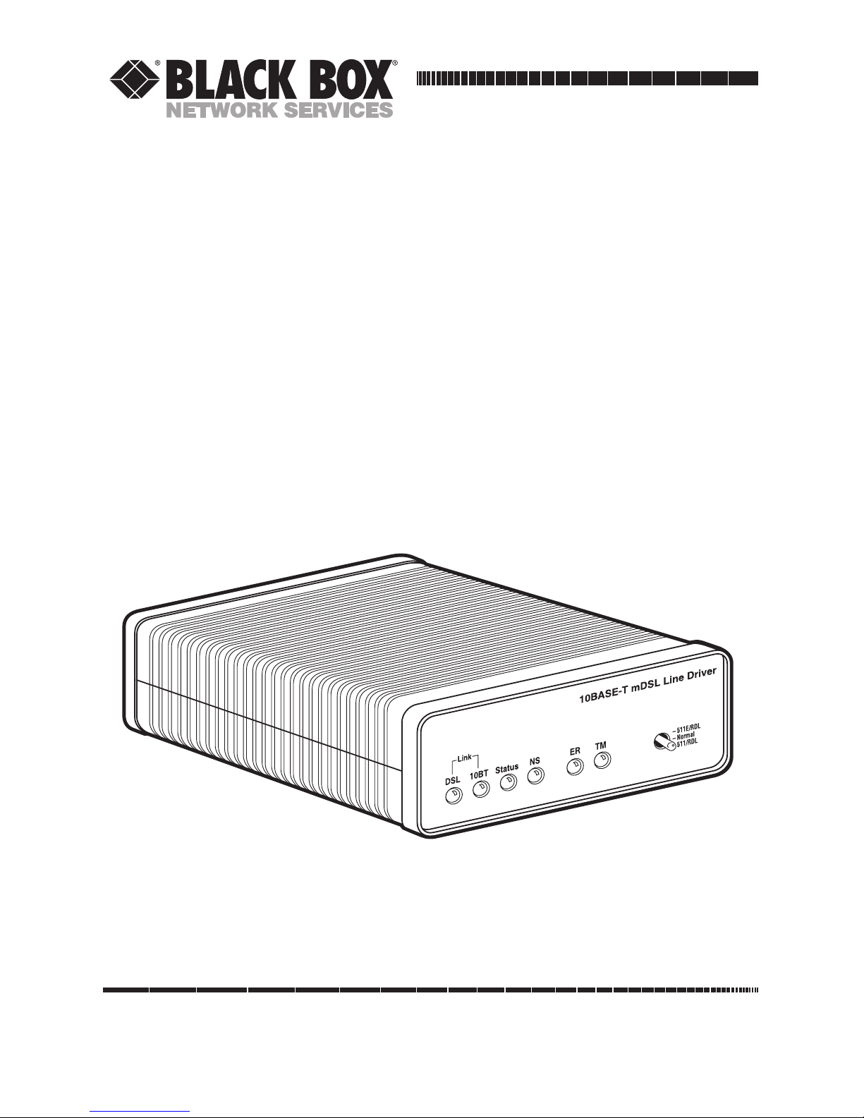
2-Wire Short-Range DSL Line Driver
(mDSL)
Page 2

1
FCC AND IC RFI STATEMENTS/CE NOTICE
FEDERAL COMMUNICATIONS COMMISSION
AND
INDUSTRY CANADA
RADIO FREQUENCY INTERFERENCE STATEMENTS
This equipment generates, uses, and can radiate radio frequency energy and if not
installed and used properly, that is, in strict accordance with the manufacturer’s
instructions, may cause interference to radio communication. It has been tested
and found to comply with the limits for a Class A computing device in accordance
with the specifications in Subpart B of Part 15 of FCC rules, which are designed to
provide reasonable protection against such interference when the equipment is
operated in a commercial environment. Operation of this equipment in a
residential area is likely to cause interference, in which case the user at his own
expense will be required to take whatever measures may be necessary to correct
the interference.
Changes or modifications not expressly approved by the party responsible
for compliance could void the user’s authority to operate the equipment.
This digital apparatus does not exceed the Class A limits for radio noise emission from
digital apparatus set out in the Radio Interference Regulation of Industry Canada.
Le présent appareil numérique n’émet pas de bruits radioélectriques dépassant les limites
applicables aux appareils numériques de la classe A prescrites dans le Règlement sur le
brouillage radioélectrique publié par Industrie Canada.
EUROPEAN UNION DECLARATION OF CONFORMITY
This equipment complies with the requirements of the European EMC Directive
89/336/EEC.
Page 3

2
2-WIRE SHORT-RANGE DSL LINE DRIVER (MDSL)
NORMAS OFICIALES MEXICANAS (NOM)
ELECTRICAL SAFETY STATEMENT
INSTRUCCIONES DE SEGURIDAD
1. Todas las instrucciones de seguridad y operación deberán ser leídas antes de
que el aparato eléctrico sea operado.
2. Las instrucciones de seguridad y operación deberán ser guardadas para
referencia futura.
3. Todas las advertencias en el aparato eléctrico y en sus instrucciones de
operación deben ser respetadas.
4. Todas las instrucciones de operación y uso deben ser seguidas.
5. El aparato eléctrico no deberá ser usado cerca del agua—por ejemplo, cerca
de la tina de baño, lavabo, sótano mojado o cerca de una alberca, etc..
6. El aparato eléctrico debe ser usado únicamente con carritos o pedestales que
sean recomendados por el fabricante.
7. El aparato eléctrico debe ser montado a la pared o al techo sólo como sea
recomendado por el fabricante.
8. Servicio—El usuario no debe intentar dar servicio al equipo eléctrico más allá
a lo descrito en las instrucciones de operación. Todo otro servicio deberá ser
referido a personal de servicio calificado.
9. El aparato eléctrico debe ser situado de tal manera que su posición no
interfiera su uso. La colocación del aparato eléctrico sobre una cama, sofá,
alfombra o superficie similar puede bloquea la ventilación, no se debe colocar
en libreros o gabinetes que impidan el flujo de aire por los orificios de
ventilación.
10. El equipo eléctrico deber ser situado fuera del alcance de fuentes de calor
como radiadores, registros de calor, estufas u otros aparatos (incluyendo
amplificadores) que producen calor.
11. El aparato eléctrico deberá ser connectado a una fuente de poder sólo del
tipo descrito en el instructivo de operación, o como se indique en el aparato.
Page 4

3
NOM STATEMENT
12. Precaución debe ser tomada de tal manera que la tierra fisica y la polarización
del equipo no sea eliminada.
13. Los cables de la fuente de poder deben ser guiados de tal manera que no
sean pisados ni pellizcados por objetos colocados sobre o contra ellos,
poniendo particular atención a los contactos y receptáculos donde salen del
aparato.
14. El equipo eléctrico debe ser limpiado únicamente de acuerdo a las
recomendaciones del fabricante.
15. En caso de existir, una antena externa deberá ser localizada lejos de las lineas
de energia.
16. El cable de corriente deberá ser desconectado del cuando el equipo no sea
usado por un largo periodo de tiempo.
17. Cuidado debe ser tomado de tal manera que objectos liquidos no sean
derramados sobre la cubierta u orificios de ventilación.
18. Servicio por personal calificado deberá ser provisto cuando:
A: El cable de poder o el contacto ha sido dañado; u
B: Objectos han caído o líquido ha sido derramado dentro del aparato; o
C: El aparato ha sido expuesto a la lluvia; o
D: El aparato parece no operar normalmente o muestra un cambio en su
desempeño; o
E: El aparato ha sido tirado o su cubierta ha sido dañada.
Page 5

4
2-WIRE SHORT-RANGE DSL LINE DRIVER (MDSL)
TRADEMARKS USED IN THIS MANUAL
Cisco®is a registered trademark of Cisco Systems.
DECnet™ is a trademark of Digital Equipment Corporation.
Novell
®
is a registered trademark, and IPX™ is a trademark, of Novell
Incorporated.
Any other trademarks mentioned in this manual are acknowledged to be the property of the
trademark owners.
Page 6

5
CONTENTS
Contents
Chapter Page
1. Specifications . . . . . . . . . . . . . . . . . . . . . . . . . . . . . . . . . . . . . . . . . . . . . . . . . . . . 6
1.1 General . . . . . . . . . . . . . . . . . . . . . . . . . . . . . . . . . . . . . . . . . . . . . . . . . . . . . . 6
1.2 Ethernet Specifications . . . . . . . . . . . . . . . . . . . . . . . . . . . . . . . . . . . . . . . . . 7
2. Introduction. . . . . . . . . . . . . . . . . . . . . . . . . . . . . . . . . . . . . . . . . . . . . . . . . . . . . 8
2.1 Description. . . . . . . . . . . . . . . . . . . . . . . . . . . . . . . . . . . . . . . . . . . . . . . . . . . 8
2.2 Features . . . . . . . . . . . . . . . . . . . . . . . . . . . . . . . . . . . . . . . . . . . . . . . . . . . . . 8
3. PPP Operational Background . . . . . . . . . . . . . . . . . . . . . . . . . . . . . . . . . . . . . . 9
4. Configuration . . . . . . . . . . . . . . . . . . . . . . . . . . . . . . . . . . . . . . . . . . . . . . . . . . 12
4.1 Plug-and-Play . . . . . . . . . . . . . . . . . . . . . . . . . . . . . . . . . . . . . . . . . . . . . . . . 12
4.2 Configuring the Hardware DIP Switches. . . . . . . . . . . . . . . . . . . . . . . . . . 13
4.2.1 Configuration DIP-Switch S2 . . . . . . . . . . . . . . . . . . . . . . . . . . . . . . 14
4.2.2 Configuration DIP-Switch S3 . . . . . . . . . . . . . . . . . . . . . . . . . . . . . . 15
5. Installation . . . . . . . . . . . . . . . . . . . . . . . . . . . . . . . . . . . . . . . . . . . . . . . . . . . . . 19
5.1 Connecting the DSL Interface . . . . . . . . . . . . . . . . . . . . . . . . . . . . . . . . . . 19
5.2 Connecting the 10BASE-T Ethernet Port to a PC (DTE) . . . . . . . . . . . . 20
5.3 Connecting the 10BASE-T Ethernet Port to a Hub (DCE) . . . . . . . . . . . 21
5.4 Power Connection . . . . . . . . . . . . . . . . . . . . . . . . . . . . . . . . . . . . . . . . . . . . 21
6. Operation. . . . . . . . . . . . . . . . . . . . . . . . . . . . . . . . . . . . . . . . . . . . . . . . . . . . . . 22
6.1 Power-Up . . . . . . . . . . . . . . . . . . . . . . . . . . . . . . . . . . . . . . . . . . . . . . . . . . . 22
6.2 LED Status Indicators . . . . . . . . . . . . . . . . . . . . . . . . . . . . . . . . . . . . . . . . . 22
6.3 Test Modes . . . . . . . . . . . . . . . . . . . . . . . . . . . . . . . . . . . . . . . . . . . . . . . . . . 25
6.3.1 Overview . . . . . . . . . . . . . . . . . . . . . . . . . . . . . . . . . . . . . . . . . . . . . . . 25
6.3.2 Restart Procedures and Timeouts . . . . . . . . . . . . . . . . . . . . . . . . . . 26
6.3.3 Loops and Patterns . . . . . . . . . . . . . . . . . . . . . . . . . . . . . . . . . . . . . . 27
6.3.4 Using the V.52 (BER) Test-Pattern Generator . . . . . . . . . . . . . . . . 28
Appendix: Transmission Distance Charts . . . . . . . . . . . . . . . . . . . . . . . . . . . . . . 29
Page 7

6
2-WIRE SHORT-RANGE DSL LINE DRIVER (MDSL)
1. Specifications
1.1. General
Clocking Modes: Internal or Receive Recovered
DTE Rate: All 64-kbps increments from 64 to 2304 kbps
Diagnostics: V.52-compliant (511/511E) pattern generator and detector with error
injection mode and Remote Loopback control by a single front-panel switch
Configuration: Externally accessible DIP switches or SNMP/HTTP managed
through the Managed Micro Rack SNMP/HTPP Card (part number
RM261C-SNMP)
Transmission Line: Single twisted-pair (2 wires)
Line Coding: CAP (Carrierless Amplitude and Phase Modulation)
Line Rates (DSL Line): 144, 272, 400, 528, 784, 1040, 1552, 2064, 2320 kbps
Line Interface: Transformer coupled, 1500-VAC isolation
Indicators: The following LEDs are displayed on the front panel:
DSL Link (Green Active): DSL Link active;
10BT Link (Green Active): Valid Ethernet connection;
Status (Flashing Yellow): Status indication from the Ethernet port;
NS (Red Active): No signal on DSP Link;
ER (Flashing Red): CRC error during normal operation, bit error during
pattern-generation test;
TM (Active Yellow): Test Mode Enabled
Connectors: (2) RJ-45
Power: +5V external desktop power supply, 100 to 240 VAC, 50-60 Hz (universal
input), 10W
Size: 1.6"H x 4.7"W x 5"D (4.1 x 11.9 x 12.7 cm)
Weight: 0.58 lb. (0.26 kg)
Page 8

7
CHAPTER 1: Specifications
1.2 Ethernet Specifications
Connector: RJ-45, 10BASE-T 802.3 Ethernet
Protocol: PPP (RFC 1661) with Bridging Control (RFC 1638)
Address Aging: Entries are deleted after 8 minutes of inactivity
Frame Latency: 1 frame
Frame Buffer: 512 frames
Ethernet Physical Connection: Pin 1 TD Data +, Pin 2 TD Data -, Pin 3 RD Data +,
Pin 6 RD Data +, Pins 4, 5, 7, 8 no connection
Page 9

8
2-WIRE SHORT-RANGE DSL LINE DRIVER (MDSL)
2. Introduction
2.1 Description
The 2-Wire Short-Range Line Driver (mDSL) is a multi-rate DSL modem that
provides seamless MAC Layer connectivity between two peered 10BASE-T LANs.
Enterprise users no longer need to hassle with a bridge and a CSU/DSU or
recurring leased-line costs. The mDSL Line Driver allows you to add additional
nodes to a LAN that has reached its maximum distance limits or separate hightraffic areas of a LAN. The Line Driver connects peered LANs and automatically
forwards and receives LAN broadcasts, multicasts, and frames across a 2-wire DSL
span. The Line Driver supports PPP (RFC 1661) and BCP (RFC 1638).
The Line Driver features include loopback diagnostics, inband SNMP/HTTP
remote management capabilities using plug-and-play, and externally accessible
configuration switches. As a symmetric DSL modem, the Line Driver offers the
same data rates in both directions over a single pair of regular telephone lines
using Carrierless Amplitude and Phase (CAP) modulation. The Line Driver
connects to the DSL line via an RJ-45 jack. The Line Driver is powered by a
universal (100 to 240-VAC) power supply.
2.2 Features
• Provides MAC Level Data Link (Layer 2) connection between two peered
10BASE-T Ethernet LANs.
• Operates transparently to higher level protocols such as TCP/IP, DECnet™,
NetBIOS, and IPX™.
• PPP (Point-to-Point Protocol, RFC 1661) with Bridge Control Protocol
(RFC 1638).
• Automatically learns, loads, and removes MAC addresses.
• Point-to-point connectivity over 2-wire mDSL up to 10 km.
• Plug-and-play slave.
• HTTP/SNMP manageable as CP (Customer Premises) unit with ME0004C
rack card as the central office unit.
• Internal or receive recovered clocking between units.
• LED indicators for 10BASE-T Link, DSL Link, Status, No Signal, Error, and
Test Mode.
Page 10

9
3. PPP Operational Background
PPP is a protocol used for multiplexed transport over a point-to-point link. PPP
operates on all full-duplex media. It’s a symmetric peer-to-peer protocol, which can
be broken into three main components:
1. A standard method to encapsulate datagrams over serial links.
2. A Link Control Protocol (LCP) to establish, configure, and test the data-link
connection.
3. A family of Network Control Protocols (NCPs) to establish and configure
different network layer protocols.
In order to establish communications over a point-to-point link, each end of the
PPP link must first announce its capabilities and agree on the parameters of the
link’s operation. This exchange is facilitated through LCP Configure-Request
packets.
Once the link has been established and optional facilities have been negotiated,
PPP will attempt to establish a network protocol. PPP will use Network Control
Protocol (NCP) to choose and configure one or more network layer protocols.
Once each network layer protocol has been configured, datagrams from the
established network layer protocol can be sent over the link. The link will remain
configured for these communications until explicit LCP or NCP packets close the
link down, or until some external event occurs.
The PPP Bridging Control Protocol (BCP), defined in RFC 1638, configures and
enables/disables the bridge protocol on both ends of the point-to-point link. BCP
uses the same packet exchange mechanism as the Link Control Protocol (LCP).
BCP is a Network Control Protocol of PPP, and bridge packets may not be
exchanged until PPP has reached the network layer protocol phase.
Applications
In situations where a routed network requires connectivity to a remote Ethernet
network, the interface on a router can be configured as a PPP IP half-bridge. The
serial line to the remote bridge functions as a Virtual Ethernet interface, effectively
extending the router’s serial-port connection to the remote network. The bridge
device sends bridge packets (BPDUs) to the router’s serial interface. The router
will receive the Layer 3 address information and will forward these packets based
on its IP address.
CHAPTER 3: PPP Operational Background
Page 11

10
2-WIRE SHORT-RANGE DSL LINE DRIVER (MDSL)
Figure 3-1 shows a typical Cisco®router with a serial interface configured as a PPP
half-bridge. The router serial interface uses a remote device that supports PPP
bridging to function as a node on the remote Ethernet network. The serial
interface on the Cisco router will have an IP address on the same Ethernet subnet
as the bridge.
Figure 3-1. Cisco router with serial interface,
configured as a PPP half-bridge.
Customer site
Service provider’s network
Ethernet LAN
Internet
Router
Bridge
Page 12

11
For example, the customer site is assigned the addresses 192.168.1.0/24 through
192.168.1.1/24. The address 192.168.1.1/24 is also the default gateway for the
remote network. The above settings remove any routing/forwarding intelligence
from the CPE. The associated Cisco configuration will set serial interface (s0) to
accommodate half-bridging for the example in Figure 3-1.
CHAPTER 3: PPP Operational Background
Page 13

12
2-WIRE SHORT-RANGE DSL LINE DRIVER (MDSL)
4. Configuration
There are two modes of operation for the Line Driver: Plug-and-Play and selfconfiguration. Both are described in this chapter.
4.1 Plug-and-Play
The Plug-and-Play feature allows ISPs, carriers, and PTTs to quickly upgrade the
link speed to configure the Customer Premise (CP) Line Driver. This feature also
allows service providers to set up all of the configurations at the Central Office (on
the rack cards) before installing the standalone units, saving time spent
configuring or re-configuring DIP switches.
The Plug-and-Play feature allows you to configure the DTE rate (bandwidth
allocation, see Switches S3-1 through S3-6) of the CP unit from the rack card at the
Central Office (CO). The standalone unit at the Customer Premise (CP) site will
automatically configure itself to the DTE rate (bandwidth allocation) of the rack
card. Other configuration parameters remain in the default setting.
Follow the instructions below to activate Plug-and-Play between CO (mDSL Rack
Card, ME0004C) and CP (mDSL Line Driver, ME0005A-10BT) units:
1. Set the mDSL Rack Card (CO) to either Internal or External clocking mode
as defined by the application.
2. Set the mDSL Line Driver (CP) to “Plug-and-Play CP” by setting all S2 and S3
DIP switches in the OFF position as described in Figure 4-1.
Figure 4-1. Typical plug-and-play application.
mDSL Rack Card,
ME0004C
(CO)
DSL span
mDSL Line
Driver,
ME0005A-10BT
(CP)
DIP switches or NMS configured
according to specific application
requirements.
DIP switches all in
OFF position.
Page 14

13
CHAPTER 4: Configuration
When the CO and CP units connect over DSL, the CP will enter a predefined
default configuration (Receive Recovered Clocking). During the negotiation
process between the units, the CO unit will configure the DTE rate/line rate on
the CP unit as defined by the settings of the CO unit. When additional bandwidth
is required, only the configuration of the CO unit should be changed. This feature
gives ISPs, LECs, and PTTs the ability to provision bandwidth on an as-needed basis
to customers.
The Plug-and-Play application will also work in an HTTP/SNMP managed system
using the Managed Micro Rack SNMP/HTTP Card (part number RM261C-SNMP)
with mDSL Rack Cards installed in a Managed Micro Rack (part number RM260).
In this application, the system administrator can configure the entire rack through
the Network Management Station (NMS) before the standalone (CP) units are
installed. For more information on the HTTP/SNMP management, please refer to
the Managed Micro Rack SNMP/HTTP Card Users’ Manual.
4.2 Configuring the Hardware DIP Switches
The mDSL Line Driver has two sets of eight DIP switches. This section describes
switch locations and explains all settings.
The 16 external switches are grouped into two eight-switch sets, and they’re
externally accessible from the underside of the Line Driver, as shown in Figure 4-2.
Figure 4-2. Underside of the mDSL Line Driver,
showing the location of the DIP switches.
1
2
3
4
56
78
1
2
3
4
56
78
ON
OFF
S2
S3
Rear
Front
Page 15

14
2-WIRE SHORT-RANGE DSL LINE DRIVER (MDSL)
The two sets of DIP switches on the underside of the mDSL Line Driver are called
S2 and S3. As Figure 4-3 shows, the orientation of all DIP switches is the same with
respect to ON and OFF positions.
Figure 4-3. Close-up of configuration switches
(all sets are identical in appearance).
4.2.1 C
ONFIGURATION
DIP-S
WITCH
S2
The only setting for S2 is for clocking mode between the mDSL Line Drivers. All
other switches are reserved for factory use and must remain in the default
configuration. Default settings are shown in Table 4-1.
Table 4-1. S2 summary.
Position Function Factory Default
S2-1 Reserved Off
S2-2 Reserved Off
S2-3 Reserved Off
S2-4 Reserved Off
S2-5 Reserved Off
S2-6 Clock Mode On
S2-7 Clock Mode Off
S2-8 Reserved Off
Switch S2-1, S2-2, S2-3, S2-4, S2-5, and S2-8
These switches are reserved for factory use and must remain in the factory-default
settings as shown in Table 4-1.
1
2
3
4
56
78
}
Receive Recover
ON
OFF
Page 16

15
Switches S2-6 and S2-7: Clock Mode
Use Switches S2-6 and S2-7 to configure internal or receive recover (clocking
derived from the remote mDSL Line Driver across the DSL span) settings. One
Line Driver (typically the CO, or “Central Office” unit) will be set for internal
clock. The remote Line Driver (typically the CP, or Customer Premises unit) will
be set for receive recover clocking. See Table 4-2.
Table 4-2. Clock mode.
CO/CP S2-6 S2-7 Clock Mode Description
Unit
CO On On Internal Line Driver generates internal,
crystal-controlled timing.
CP On Off Receive Recover Line Driver receives its timing
from the CO unit over the DSL
span.
4.2.2 C
ONFIGURATION
DIP-S
WITCH
S3
Use the DIP switches in Switch S3 to set the DTE Rate (for LAN bandwidth
allocation), the transmit data sampling point, and to reset the unit to its software
default settings. Table 4-3 summarizes default positions of DIP-switch S3. Detailed
descriptions of each switch follow the table.
Table 4-3. S3 summary.
Position Function Factory Default
S3-1 DTE Rate On
S3-2 DTE Rate Off
S3-3 DTE Rate Off
S3-4 DTE Rate Off
S3-5 DTE Rate On
S3-6 DTE Rate On
S3-7 Reset Software Defaults On Normal Operation
S3-8 Reserved On
CHAPTER 4: Configuration
}
768 kbps
Page 17

16
2-WIRE SHORT-RANGE DSL LINE DRIVER (MDSL)
Switch S3-1 through S3-6: DTE Rate
Use Switch S3-1 through S3-6 to provision bandwidth to the LAN in 64-kbps
increments up to 2.304 Mbps. Peak bandwidth utilization on the local domain on
an Ethernet LAN runs typically between 15% to 20% (1.5 Mbps to 2 Mbps) of the
maximum bit rate of 10 Mbps. Traffic between LANs typically runs even lower —
between 2% to 7% (200 kbps to 700 kbps) of the maximum bit rate depending
upon application and environmental conditions. This is the amount of traffic that
will run across the DSL span.
Set Switches 3-1 through S3-6 to allocate bandwidth based upon expected LAN-toLAN traffic rates. As an example, set applications with low LAN-to-LAN bandwidth
content between 64 kbps and 576 kbps. Applications with high-bandwidth LAN-toLAN content should be set between 576 kbps and 2.304 Mbps as required.
Table 4-4. Bandwidth settings.
S3-1 S3-2 S3-3 S3-4 S3-5 S3-6 DTE Rate (kbps)
Off Off On On On On 64
On On Off On On On 128
Off On Off On On On 192
On Off Off On On On 256
Off Off Off On On On 320
On On On Off On On 384
Off On On Off On On 448
On Off On Off On On 512
Off Off On Off On On 576
On On Off Off On On 640
Off On Off Off On On 704
On Off Off Off On On 768
Off Off Off Off On On 832
On On On On Off On 896
OffOnOnOnOffOn 960
On Off On On Off On 1024
Off Off On On Off On 1088
On On Off On Off On 1152
Off On Off On Off On 1216
On Off Off On Off On 1280
Off Off Off On Off On 1344
Page 18

17
Table 4-4 (continued). Bandwidth settings.
S3-1 S3-2 S3-3 S3-4 S3-5 S3-6 DTE Rate (kbps)
On On On Off Off On 1408
Off On On Off Off On 1472
On Off On Off Off On 1536
On On Off Off Off On 1600
Off On Off Off Off On 1664
On Off Off Off Off On 1728
Off Off Off Off Off On 1792
On On On On On Off 1856
Off On On On On Off 1920
On Off On On On Off 1984
Off Off On On On Off 2048
On On Off On On Off 2112
Off On Off On On Off 2176
On Off Off On On Off 2240
Off Off Off On On Off 2304
NOTE
The actual line rate of the Line Driver is determined by the selection of
the DTE rate. To see the line rate associated with various DTE rates,
refer to the distance charts in the Appendix.
Switch S3-7: Reset Software Defaults
Use Switch S3-7 to reset the software-configured factory defaults. This feature is
applicable only using the Managed Micro Rack SNMP/HTTP Card (part number
RM261C-SNMP) to SNMP through the mDSL Line Driver central office to manage
your units. For more information, please refer to the Managed Micro Rack
SNMP/HTTP Card Users’ Manual.
Table 4-5. Reset software defaults.
S3-7 Setting
On Normal Operation
Off Reset
CHAPTER 4: Configuration
Page 19

18
2-WIRE SHORT-RANGE DSL LINE DRIVER (MDSL)
Switch S3-8: Reserved
Switch S3-8 is reserved for factory use and must remain in the On position.
Page 20

19
5. Installation
When the mDSL Line Driver has been properly configured, it may be connected to
the DSL twisted-pair interface, the 10BASE-T Ethernet Interface, and the power
source. This section describes these connections.
Figure 5-1. Connectors on the mDSL Line Driver.
5.1 Connecting the DSL Interface
The mDSL Line Driver supports communication between 10BASE-T hubs or
workstations at distances to 5 miles (8 km) over 24 AWG (0.5 mm) twisted-pair
wire. There are two requirements for installing the mDSL Line Driver:
1. These units operate as a pair. Both units at the end of the twisted-pair DSL
span must be set for the same DTE rate.
2. To function properly, the mDSL Line Driver needs one twisted pair of
metallic wire. This twisted pair must be unconditioned, dry, metallic wire,
between 19 (0.9 mm) and 26 AWG (0.4 mm); the higher number gauges will
limit distance. Standard dial-up telephone circuits, leased circuits that run
through signal equalization equipment, or standard, flat modular telephone
type cable are not acceptable.
The RJ-45 connector on the mDSL Line Driver’s twisted-pair interface is polarity
insensitive and is wired for a two-wire interface. The signal/pin relationships are
shown in Figure 5-2.
CHAPTER 5: Installation
Power
DSL
Interface
DSL
interface
10BASE-T
interface
Page 21

20
2-WIRE SHORT-RANGE DSL LINE DRIVER (MDSL)
Figure 5-2. Twisted-pair line interface.
5.2 Connecting the 10BASE-T Ethernet Port to a PC (DTE)
The 10BASE-T interface is configured as DTE (Data Terminal Equipment). If the
mDSL Line Driver is to connect to another DTE device such as a 10BASE-T
network interface card, construct a 10BASE-T crossover cable and connect the
wires as shown in Figure 5-3.
10BASE-T Port 10BASE-T DTE
RJ-45 Pin No. RJ-45 Pin No.
1 (TD+) 1 (TD+)
2 (TD-) 2 (TD-)
3 (RD+) 3 (RD+)
6 (RD-) 6 (RD-)
Figure 5-3. Ethernet port to PC connections.
1 - - - - - - - - - - - - - - - - 1 Not connected
2 - - - - - - - - - - - - - - - - 2 Not connected
3 - - - - - - - - - - - - - - - - 3 Not connected
4 - - - - - - - - - - - - - - - - 4 (2-wire Tip)
5 - - - - - - - - - - - - - - - - 5 (2-wire Ring)
6 - - - - - - - - - - - - - - - - 6 Not connected
7 - - - - - - - - - - - - - - - - 7 Not connected
8 - - - - - - - - - - - - - - - - 8 Not connected
Page 22

21
5.3 Connecting the 10BASE-T Ethernet Port to a Hub (DCE)
The 10BASE-T interface is configured as DTE (Data Terminal Equipment), just
like a 10BASE-T network interface card in a PC. Therefore, it “expects” to connect
to a 10BASE-T hub using a straight-through RJ-45 cable. Use Figure 5-4 to
construct a cable to connect the 10BASE-T interface to a 10BASE-T hub.
10BASE-T Port 10BASE-T Hub
RJ-45 Pin No. RJ-45 Pin No.
1 (TD+) 1 (RD+)
2 (TD-) 2 (RD-)
3 (RD+) 3 (TD+)
6 (RD-) 6 (TD-)
Figure 5-4. Port-to-hub connections.
Figure 5-5. Ethernet RJ-45 connector pinout.
5.4 Power Connection
The mDSL Line Driver uses a 5-VDC, 2-A, 100- to 240-VAC universal input power
supply (center pin is +5V). The power supply has a male IEC-320 power entry
connector. This power supply connects to the Line Driver via a barrel jack on the
rear panel.
WARNING
There are no user-serviceable parts in the Line Driver’s power supply.
Contact Black Box Technical Support at 724-746-5500 for details.
CHAPTER 5: Installation
1 - - - - - - - - - - - - - - - - 1 TD+ (data output from ME0005A-10BT)
2 - - - - - - - - - - - - - - - - 2 TD- (data output from ME0005A-10BT)
3 - - - - - - - - - - - - - - - - 3 RD+ (data input to ME0005A-10BT)
4 - - - - - - - - - - - - - - - - 4 Not connected
5 - - - - - - - - - - - - - - - - 5 Not connected
6 - - - - - - - - - - - - - - - - 6 RD - (data input to ME0005A-10BT)
7 - - - - - - - - - - - - - - - - 7 Not connected
8 - - - - - - - - - - - - - - - - 8 Not connected
Page 23

22
2-WIRE SHORT-RANGE DSL LINE DRIVER (MDSL)
6. Operation
When the mDSL Line Driver has been properly configured and installed, it should
operate transparently. This section describes power-up, LED status monitors, and
the built-in loopback test modes.
6.1 Power-Up
Before applying power to the Line Driver, please read Section 5.4 and make sure
that the unit is connected to the appropriate power source.
6.2 LED Status Indicators
The mDSL Line Driver features six front-panel LEDs that monitor connections on
the DSL and 10BASE-T links, signaling, error, and test modes. Figure 6-1 shows the
location of each LED. Descriptions of each LED follow Figure 6-1.
Figure 6-1. Front panel of the Line Driver.
• DSL Link: (Active Green) Solid green (On) indicates that the end-to-end DSL
Framer Link is up, signifying that the link across the DSL span is active. The
DSL Link LED is Off when the link is down.
• Status: Blinks yellow from one to eleven times to indicate system status. Each
pulse pattern is separated by a 2-second “off” period. Greater pulse patterns
have higher priority (buffer saturation has greater priority than an empty MAC
table). Valid system statuses are:
1 pulse = system status is okay
2 pulses = no MAC entries in the MAC Address Table
3 pulses = Clear to Send (CTS) or Carrier Detect (DCD) from base
unit are not asserted
DSL 10BT Status NS ER TM
Page 24

23
CHAPTER 6: Operation
4 pulses = Line Driver’s buffer is saturated
5 pulses = WAN receive frame(s) too large
6 pulses = WAN receive frame(s) not octet aligned
7 pulses = WAN receive frame(s) aborted
8 pulses = Detected WAN receive frame(s) with CRC
9 pulses = Detected LAN receive frame(s) too large
10 pulses = Detected LAN receive frame(s) not octet aligned
11 pulses = Detected LAN receive frame(s) with bad CRC
• 10BT Link: (Active Green) Solid green indicates that the 10BASE-T Ethernet
interface has detected a valid SQE heartbeat, signifying a valid 10BASE-T
connection.
• NS: (Active Red) Solid red indicates that the Digital Signal Processors (DSPs)
are not linked.
• ER: (Active Red) Flashing red indicates CRC Errors on DSL (Framer) side if
DSL Link is active or if bit errors are received during loop/BER test. ER flashes
once to indicate a CRC error (during normal operation) or bit errors (during
Remote Loopback 511/511E tests).
• TM: (Active Yellow) Solid Yellow indicates an Active Test Mode. The unit may
be placed in test mode by the local user or by the remote user.
Page 25

24
2-WIRE SHORT-RANGE DSL LINE DRIVER (MDSL)
Table 6-1. LED status, local Line Driver.
Local
10BASE-T DSL Status NS ER TM
Power On Green* Off Flashing On Off Off
DSL Link Green* Green Flashing Off Off Off
Link Brk Green* Off Flashing Off Off Off
Brk +10s Green* Off Flashing On Off Off
RDL Green* Green Flashing Off Off On
RDL +511 Green* Off Flashing Off Off On
Table 6-2. LED status, remote Line Driver.
Remote
10BASE-T DSL Status NS ER TM
Power On Green* Off Flashing On Off Off
DSL Link Green* Off Flashing Off Off Off
Link Brk Green* Off Flashing Off Off Off
Brk +10s Green* Off Flashing On Off Off
RDL Green* Off Flashing Off Off On
RDL +511 Green* Off Flashing Off Off On
Link Brk = DSL link broken
Brk +10s = 10 seconds following link break
Green* = Green if a valid 10BASE-T connection is detected
Page 26

25
6.3 Test Modes
The mDSL Line Driver offers a proprietary Remote Loopback test mode. It also
has a built-in V.52 BER test-pattern generator to evaluate the communication status
between units. Activate this test mode by toggling the Test Mode switch on the
unit’s front panel.
6.3.1 O
VERVIEW
Figure 6-2 shows the major elements used in the loopback and 511 pattern tests
available in the mDSL Line Driver. Each block has several functions. Following
Figure 6-2 are descriptions of the elements during Test Modes.
Figure 6-2. Block diagram: two mDSL Line Drivers
communicating over the DSL span.
• Framer: The framer determines the status of the line. In normal operation,
the framer transmits and expects to receive framed packets from the far end. If
the framer receives framed packets from the far end, the DSL Link LED will
turn on. If framed packets are not received, the DSL Link LED will turn off.
The restart procedure uses this information to determine if a valid connection
is made (cable disconnect, poor cable quality, etc). In normal Data Mode, if
the box receives four seconds of unframed packets it will restart the box and
begin trying to re-establish a connection with the the remote mDSL Line
Driver. The distinction between framed packets and unframed packets
becomes important when we discuss the pattern generator.
• Pattern Gen./Det.: This part of the processor generates and detects the
511/511E patterns. When transmitting 511 patterns, the information is
unframed (because it originates after the framer) and is intended to be
evaluated only by another processor. If the units are transmitting data and the
pattern generator is enabled on one end of the link, the far end will begin
CHAPTER 6: Operation
Framer
Processor
Processor
Framer
Pattern
Gen./Det.
Pattern
Gen./Det.
Loop
Control
Loop
Control
DSL
Span
Page 27

26
2-WIRE SHORT-RANGE DSL LINE DRIVER (MDSL)
receiving unframed packets and assume that the line has gone down. During
test modes, the pattern generator is forced to time out before it can cause the
DSL link to go down.
• Loop Control: This part of the processor is used to control Remote Loopback
test mode. In a remote loop, the 511/511/E data is looped back to the line
and to the remote unit over the DSL span.
6.3.2 R
ESTART
P
ROCEDURE ANDTIMEOUTS
The restart procedure is in place to allow the Line Drivers to re-establish a
connection after the framer begins seeing unframed packets. Table 6-3 shows the
amount of time the framer must see consecutive unframed packets before the Line
Driver will restart and try to establish a new line connection. The reason that there
are different restart times will become apparent after reading the rest of the
document. The 511/511E timeout shown refers to the amount of time the
511/511E pattern will be valid. At the end of this time the pattern will
automatically turn itself off and the normal data path will be re-established. The
ER LED will flash, indicating to the user that the test has timed out. The ER LED
will stop flashing once the 511/511E switch is placed into the normal position.
Table 6-3. Test mode timing.
Item Elapsed Time (seconds)
Startup 50
Data Mode 4
511/511E Generator Enabled 60 (The generator will stop after
45 seconds.)
Remote End of an RDL 60
511/511E Timeout 45 (The pattern generator will
automatically turn off after 45 seconds.
The ER LED will flash until you turn off
the 511/511E switch.)
Page 28

27
CHAPTER 6: Operation
6.3.3 L
OOPS AND
P
ATTERNS
The following section describes the Remote Loopback/BER test modes.
Remote Digital
When Remote Loop/511 or Remote Loop/511/E is enabled via the front-panel
switch, the remote unit’s restart timer is set to one minute. This is because when
the 511/511E generator is initiated on the local unit, the remote framer begins
seeing unframed packets. The remote Line Driver cannot distinguish the
511/511E pattern from the line being disconnected, so the restart timer has been
lengthened to allow the pattern generator to function. Once the 511/511E test is
started, the local Line Driver changes its restart timer to one minute. The pattern
originates within the processor and is sent to the remote Line Driver. It is then
looped back to the local Line Driver where it is evaluated for errors. After 45
seconds, the pattern generator will timeout and stops sending the pattern. The ER
LED will begin blinking until you turn off the 511/511E switch.
Figure 6-3. Remote Digital loop.
Symbol Indicators
This symbol designates the origination or the termination of a data path. The
direction of the arrow connected distinguishes the two data paths.
This symbol designates an invalid data path. If there is data present, it should
be ignored.
X
X
X
X
X
Framer
Processor
Processor
Framer
Pattern
Gen./Det.
Pattern
Gen./Det.
Loop
Control
Loop
Control
Line
Page 29

28
2-WIRE SHORT-RANGE DSL LINE DRIVER (MDSL)
6.3.4 U
SING THE
V.52 (BER) T
EST-PATTERNGENERATOR
To use the V.52 BER tests in conjunction with the Remote Digital Loopback tests,
follow these instructions:
1. Locate the Remote Loop/511 and Remote Loop/511E toggle switch on the
Line Driver’s front panel and move it DOWN. This activates the Remote Loop
with V.52 BER and transmits a “511” test pattern into the loop. If any errors
are present, the local Line Driver’s red “ER” LED will blink sporadically.
2. If the above test indicates no errors are present, move the test switch V.52
toggle switch UP, activating the 511/E test with intentional errors present. If
the test is working properly, the local Line Driver’s red ER LED will blink. A
successful 511/E test will confirm that the link is in place, and that the Line
Driver’s built-in 511 generator and detector are working properly.
Page 30

29
APPENDIX: Transmission Distance Charts
Appendix. Transmission Distance
Charts
Table A-1. Transmission distance, 26 to 20 AWG.
Line DTE 26 AWG (0.4 mm) 24 AWG (0.5 mm) 22 AWG (0.6 mm) 20 AWG (0.8 mm)
Rate Rates ft. mi. km ft. mi. km ft. mi. km ft. mi. km
(kbps) (kbps)
144 64, 128 21,400 4 6.5 30,700 5.8 9.4 42,980 8.1 13.1 55,260 10.5 16.8
272 192, 256 20,300 3.8 6.2 30,600 5.8 9.4 42,840 8.1 13.1 55,080 10.4 16.8
400 320, 384 18,600 3.5 5.7 29,100 5.5 8.9 40,740 7.7 12.4 52,380 9.9 16
528 448, 512 17,400 3.3 5.3 26,100 4.9 8 36,540 6.9 11.1 46,980 8.9 14.3
784 576–768 15,800 3 4.8 22,600 4.3 6.9 29,380 5.6 9 38,420 7.3 11.7
1040 832–1024 15,500 2.9 4.7 22,100 4.2 6.7 28,730 5.4 8.8 37,570 7.1 11.5
1552 1088–1536 13,600 2.6 4.2 19,200 3.6 5.9 24,960 4.7 7.6 32,640 6.2 10
2064 1600–2048 12,200 2.3 3.7 17,200 3.3 5.2 22,360 4.2 6.8 29,240 5.5 8.9
2320 2112–2304 11,500 2.2 3.5 15,800 3 4.8 20,540 3.9 6.3 26,860 5.1 8.2
Table A-2. Transmission distance, 19 to 16 AWG.
Line Rate DTE Rates 19 AWG (0.9 mm) 18 AWG (1 mm) 16 AWG (1.2 mm)
(kbps) (kbps) ft. mi. km ft. mi. km ft. mi. km
144 64, 128 64,470 12.2 19.7 70,610 13.4 21.5 90,784 17.2 27.7
272 192, 256 61,200 11.6 18.7 70,380 13.3 21.5 90,488 17.1 27.6
400 320, 384 52,900 10 16 66,930 12.7 20.4 86,053 16.3 26.2
528 448, 512 49,590 9.4 15.1 60,030 11.3 18.3 77,181 14.6 23.5
784 576–768 42,940 8.1 13.1 51,980 9.8 15.8 67,974 12.9 20.7
1040 832–1024 41,990 7.9 12.8 50,830 9.6 15.5 66,470 12.6 20.3
1552 1088–1536 34,580 6.5 10.5 44,160 8.4 13.5 57,748 10.9 17.6
2064 1600–2048 30,960 5.9 9.4 39,560 7.5 12.1 51,732 9.8 15.8
2320 2112–2304 28,440 5.4 8.7 36,340 6.9 11.1 47,522 9 14.5
Page 31

1000 Park Drive • Lawrence, PA 15055-1018 • 724-746-5500 • Fax 724-746-0746
© Copyright 2002. Black Box Corporation. All rights reserved.
 Loading...