

Black Box ME0004C-G703, ME0004C-10BT, ME0004C-RS530, ME0004C-V35, ME0004C-V24 User Manual
...Page 1
CUSTOMER
SUPPORT
INFORMATION
Order toll-free in the U.S.: Call 877-877-BBOX (outside U.S. call 724-746-5500)
FREE technical support 24 hours a day, 7 days a week: Call 724-746-5500 or fax 724-746-0746
Mailing address: Black Box Corporation, 1000 Park Drive, Lawrence, PA 15055-1018
Web site: www.blackbox.com • E-mail: info@blackbox.com
NOVEMBER 2001
ME0004C-10BT
ME0004C-G703
ME0004C-RS530
ME0004C-V24
ME0004C-V35
ME0004C-X21
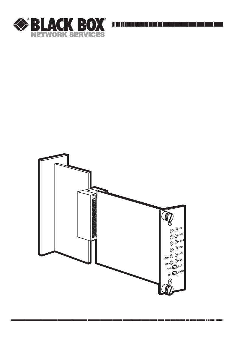
High-Speed 2-Wire Short-Range DSL
Line Driver
(mDSL Rack Card)
Page 2

1
FCC AND IC RFI STATEMENTS
FEDERAL COMMUNICATIONS COMMISSION
AND
INDUSTRY CANADA
RADIO FREQUENCY INTERFERENCE STATEMENTS
This equipment generates, uses, and can radiate radio frequency energy and if not
installed and used properly, that is, in strict accordance with the manufacturer’s
instructions, may cause interference to radio communication. It has been tested
and found to comply with the limits for a Class A computing device in accordance
with the specifications in Subpart B of Part 15 of FCC rules, which are designed to
provide reasonable protection against such interference when the equipment is
operated in a commercial environment. Operation of this equipment in a
residential area is likely to cause interference, in which case the user at his own
expense will be required to take whatever measures may be necessary to correct
the interference.
Changes or modifications not expressly approved by the party responsible
for compliance could void the user’s authority to operate the equipment.
This digital apparatus does not exceed the Class A limits for radio noise emission from
digital apparatus set out in the Radio Interference Regulation of Industry Canada.
Le présent appareil numérique n’émet pas de bruits radioélectriques dépassant les limites
applicables aux appareils numériques de la classe A prescrites dans le Règlement sur le
brouillage radioélectrique publié par Industrie Canada.
EUROPEAN UNION DECLARATION OF CONFORMITY
This equipment complies with the requirements of the European EMC Directive
89/336/EEC.
Page 3

2
HIGH-SPEED 2-WIRE SHORT-RANGE DSL LINE DRIVER RACK CARD
NORMAS OFICIALES MEXICANAS (NOM)
ELECTRICAL SAFETY STATEMENT
INSTRUCCIONES DE SEGURIDAD
1. Todas las instrucciones de seguridad y operación deberán ser leídas antes de
que el aparato eléctrico sea operado.
2. Las instrucciones de seguridad y operación deberán ser guardadas para
referencia futura.
3. Todas las advertencias en el aparato eléctrico y en sus instrucciones de
operación deben ser respetadas.
4. Todas las instrucciones de operación y uso deben ser seguidas.
5. El aparato eléctrico no deberá ser usado cerca del agua—por ejemplo, cerca
de la tina de baño, lavabo, sótano mojado o cerca de una alberca, etc..
6. El aparato eléctrico debe ser usado únicamente con carritos o pedestales que
sean recomendados por el fabricante.
7. El aparato eléctrico debe ser montado a la pared o al techo sólo como sea
recomendado por el fabricante.
8. Servicio—El usuario no debe intentar dar servicio al equipo eléctrico más allá
a lo descrito en las instrucciones de operación. Todo otro servicio deberá ser
referido a personal de servicio calificado.
9. El aparato eléctrico debe ser situado de tal manera que su posición no
interfiera su uso. La colocación del aparato eléctrico sobre una cama, sofá,
alfombra o superficie similar puede bloquea la ventilación, no se debe colocar
en libreros o gabinetes que impidan el flujo de aire por los orificios de
ventilación.
10. El equipo eléctrico deber ser situado fuera del alcance de fuentes de calor
como radiadores, registros de calor, estufas u otros aparatos (incluyendo
amplificadores) que producen calor.
11. El aparato eléctrico deberá ser connectado a una fuente de poder sólo del
tipo descrito en el instructivo de operación, o como se indique en el aparato.
Page 4

3
NOM STATEMENT
12. Precaución debe ser tomada de tal manera que la tierra fisica y la polarización
del equipo no sea eliminada.
13. Los cables de la fuente de poder deben ser guiados de tal manera que no
sean pisados ni pellizcados por objetos colocados sobre o contra ellos,
poniendo particular atención a los contactos y receptáculos donde salen del
aparato.
14. El equipo eléctrico debe ser limpiado únicamente de acuerdo a las
recomendaciones del fabricante.
15. En caso de existir, una antena externa deberá ser localizada lejos de las lineas
de energia.
16. El cable de corriente deberá ser desconectado del cuando el equipo no sea
usado por un largo periodo de tiempo.
17. Cuidado debe ser tomado de tal manera que objectos liquidos no sean
derramados sobre la cubierta u orificios de ventilación.
18. Servicio por personal calificado deberá ser provisto cuando:
A: El cable de poder o el contacto ha sido dañado; u
B: Objectos han caído o líquido ha sido derramado dentro del aparato; o
C: El aparato ha sido expuesto a la lluvia; o
D: El aparato parece no operar normalmente o muestra un cambio en su
desempeño; o
E: El aparato ha sido tirado o su cubierta ha sido dañada.
Page 5

4
HIGH-SPEED 2-WIRE SHORT-RANGE DSL LINE DRIVER RACK CARD
TRADEMARKS USED IN THIS MANUAL
DECnet™ is a trademark of Digital Equipment Corporation.
Internet Explorer
®
is a registered trademark of Microsoft Corporation.
IPX™ is a trademark of Novell Incorporated.
NetBIOS
®
is a registered trademark of International Business Machines
Corporation.
Netscape
®
is a registered trademark of Netscape Communications Corporation.
Any other trademarks mentioned in this manual are acknowledged to be the property of the
trademark owners.
Page 6

5
CONTENTS
Contents
Chapter Page
1. Specifications . . . . . . . . . . . . . . . . . . . . . . . . . . . . . . . . . . . . . . . . . . . . . . . . . . . . 7
2. Introduction. . . . . . . . . . . . . . . . . . . . . . . . . . . . . . . . . . . . . . . . . . . . . . . . . . . . . 8
2.1 Description. . . . . . . . . . . . . . . . . . . . . . . . . . . . . . . . . . . . . . . . . . . . . . . . . . . 8
2.2 Features . . . . . . . . . . . . . . . . . . . . . . . . . . . . . . . . . . . . . . . . . . . . . . . . . . . . . 8
3. Configuration . . . . . . . . . . . . . . . . . . . . . . . . . . . . . . . . . . . . . . . . . . . . . . . . . . 10
3.1 Configuring the Hardware Switches . . . . . . . . . . . . . . . . . . . . . . . . . . . . . 10
3.1.1 Reversible Interface Driver Board. . . . . . . . . . . . . . . . . . . . . . . . . . . 11
3.1.2 Connecting to a DTE Device. . . . . . . . . . . . . . . . . . . . . . . . . . . . . . . 12
3.1.3 Connecting to a DCE Device. . . . . . . . . . . . . . . . . . . . . . . . . . . . . . . 12
3.1.4 Configuring the X.21 Interface Module. . . . . . . . . . . . . . . . . . . . . . 12
3.1.5 Configuring DIP-Switch Set S1 . . . . . . . . . . . . . . . . . . . . . . . . . . . . . 12
3.1.6 Configuring DIP-Switch Set S2 . . . . . . . . . . . . . . . . . . . . . . . . . . . . . 13
3.1.7 Configuring DIP-Switch Set S3 . . . . . . . . . . . . . . . . . . . . . . . . . . . . . 15
3.2 mDSL Rack Card Plug-and-Play . . . . . . . . . . . . . . . . . . . . . . . . . . . . . . . . . 17
3.3 Configuring the Rear Interface Card. . . . . . . . . . . . . . . . . . . . . . . . . . . . . 18
3.3.1 DB25 (RS-530 and V.24) Rear Card Strap Settings . . . . . . . . . . . . . 19
3.3.2 M/34 (V.35) Rear Card Strap Settings . . . . . . . . . . . . . . . . . . . . . . . 21
3.3.3 DB15 (X.21) Rear Card Strap Settings . . . . . . . . . . . . . . . . . . . . . . . 22
4. Installation . . . . . . . . . . . . . . . . . . . . . . . . . . . . . . . . . . . . . . . . . . . . . . . . . . . . . 27
4.1 The Rack Chassis . . . . . . . . . . . . . . . . . . . . . . . . . . . . . . . . . . . . . . . . . . . . . 27
4.2 Installing the mDSL Rack Card into the Chassis. . . . . . . . . . . . . . . . . . . . 28
4.3 Wiring the mDSL Rack Card . . . . . . . . . . . . . . . . . . . . . . . . . . . . . . . . . . . 29
4.3.1 Connection to the Twisted-Pair Interface . . . . . . . . . . . . . . . . . . . . 29
4.3.2 Two-Wire Cable Connection via RJ-45 . . . . . . . . . . . . . . . . . . . . . . . 29
5. Operation. . . . . . . . . . . . . . . . . . . . . . . . . . . . . . . . . . . . . . . . . . . . . . . . . . . . . . 30
5.1 LED Status Indicators . . . . . . . . . . . . . . . . . . . . . . . . . . . . . . . . . . . . . . . . . 30
5.2 Test Modes . . . . . . . . . . . . . . . . . . . . . . . . . . . . . . . . . . . . . . . . . . . . . . . . . . 31
5.2.1 Overview . . . . . . . . . . . . . . . . . . . . . . . . . . . . . . . . . . . . . . . . . . . . . . . 31
5.2.2 Restart Procedure and Timeouts . . . . . . . . . . . . . . . . . . . . . . . . . . . 32
5.2.3 Loops and Patterns. . . . . . . . . . . . . . . . . . . . . . . . . . . . . . . . . . . . . . . 33
5.2.4 Using the V.52 (BER) Test-Pattern Generator . . . . . . . . . . . . . . . . 38
Appendix A. Terminal Interface Pin Assignments . . . . . . . . . . . . . . . . . . . . . . . 39
Appendix B. Distance Tables . . . . . . . . . . . . . . . . . . . . . . . . . . . . . . . . . . . . . . . . 42
Appendix C. Line Interface Pin Assignments . . . . . . . . . . . . . . . . . . . . . . . . . . . 43
Page 7

6
HIGH-SPEED 2-WIRE SHORT-RANGE DSL LINE DRIVER RACK CARD
Chapter Page
Appendix D. G.703/G.704 Rear Card Module . . . . . . . . . . . . . . . . . . . . . . . . . . 44
D.1 Description . . . . . . . . . . . . . . . . . . . . . . . . . . . . . . . . . . . . . . . . . . . . . . . . . 44
D.2 Typical Application. . . . . . . . . . . . . . . . . . . . . . . . . . . . . . . . . . . . . . . . . . . 44
D.2.1 Network Termination Application. . . . . . . . . . . . . . . . . . . . . . . . . . 44
D.2.2 Network Extension Application . . . . . . . . . . . . . . . . . . . . . . . . . . . . 45
D.3 Configuration . . . . . . . . . . . . . . . . . . . . . . . . . . . . . . . . . . . . . . . . . . . . . . . 46
D.3.1 DIP-Switch Configuration. . . . . . . . . . . . . . . . . . . . . . . . . . . . . . . . . 46
D.3.2 Jumper Configuration. . . . . . . . . . . . . . . . . . . . . . . . . . . . . . . . . . . . 48
D.4 Installing the Rear Card and Front Function Card . . . . . . . . . . . . . . . . . 48
D.5 Making Interface Connections . . . . . . . . . . . . . . . . . . . . . . . . . . . . . . . . . 49
D.5.1 Connect Twisted Pair (120 ohm) to G.703/G.704 Network . . . . . 49
D.5.2 Connect Dual Coaxial Cable (75 ohm) to G.703/G.704 Network 50
Appendix E. 10BASE-T Ethernet Rear Card Module. . . . . . . . . . . . . . . . . . . . . 52
E.1 Description. . . . . . . . . . . . . . . . . . . . . . . . . . . . . . . . . . . . . . . . . . . . . . . . . . 52
E.2 Configuration . . . . . . . . . . . . . . . . . . . . . . . . . . . . . . . . . . . . . . . . . . . . . . . 53
E.3 Connecting the Interface Driver Board. . . . . . . . . . . . . . . . . . . . . . . . . . . 53
E.4 Installing the Rear Interface Card and the Front Function Card . . . . . . 54
E.5 Connecting to the 10BASE-T Ethernet Port . . . . . . . . . . . . . . . . . . . . . . . 55
E.5.1 Connecting the 10BASE-T Ethernet Port to a Hub . . . . . . . . . . . . 56
E.5.2 Connecting the 10BASE-T Ethernet Port to a PC (DTE). . . . . . . . 56
E.5.3 Connecting the Line Interface . . . . . . . . . . . . . . . . . . . . . . . . . . . . . 57
E.6 Operation. . . . . . . . . . . . . . . . . . . . . . . . . . . . . . . . . . . . . . . . . . . . . . . . . . . 58
E.6.1 Power-Up . . . . . . . . . . . . . . . . . . . . . . . . . . . . . . . . . . . . . . . . . . . . . . 58
E.6.2 LED Status Indicators . . . . . . . . . . . . . . . . . . . . . . . . . . . . . . . . . . . . 58
Page 8

7
CHAPTER 1: Specifications
1. Specifications
Transmission Format: Synchronous
Transmission Line: Two-wire unconditioned twisted pair
Clocking: Internal, external, or receive recovered clock
Interface Modules: 10BASE-T, G.703/G.704, RS-530, V.24, V.35, X.21
Line Rates: 144, 272, 400, 528, 784, 1040, 1552, 2064, and 2320 kbps
DTE Rates: 64, 128, 192, 256, 320, 384, 448, 512, 576, 640, 704, 768, 832, 896, 960,
1024, 1088, 1152, 1216, 1280, 1344, 1408, 1472, 1536, 1600, 1664, 1728, 1792, 1856,
1920, 1984, 2048, 2112, 2176, 2240, and 2304 kbps
Diagnostics: V.52-compliant bit error rate pattern (511/511E pattern) generator
and detector with error injection mode; Local Line Loopback and Remote Digital
Loopback, activated by front-panel switch or via serial interface
LED Status Indicators: TD, RD, CTS, CD, DTR, NS (no signal), ER (error), and
TM (test mode)
Connectors: RJ-45 or terminal block on line side; DB25 female, M/34 female,
DB15 female, or dual BNC on serial interface side, depending upon which
interface module is installed
Temperature Range: 32 to 122°F (0 to 50°C)
Altitude: Up to 15,000 feet (4572 m)
Humidity: 5 to 95% noncondensing
Power: 90 to 264 VAC, 50–60 Hz (universal input), 10 watts
Size: Front Card: 3.1"H x 0.95"W x 4.8"D (7.9 x 2.4 x 12.2 cm); Rear Card: 2.8"H x
0.95"W x 3.3"D (7.1 x 2.4 x 8.4 cm)
Weight: Front Card: 0.22 lb. (0.1 kg); Rear Card (M/34 with V.35 interface):
0.16 lb. (0.07 kg); Rear Card (DB25/RS-232 interface): 0.12 lb. (0.05 kg); Rear
Card (Dual BNC): 0.2 lb. (0.09 kg); Rear Card (DB15): 0.12 lb. (0.05 kg)
Page 9

8
HIGH-SPEED 2-WIRE SHORT-RANGE DSL LINE DRIVER RACK CARD
2. Introduction
2.1 Description
The High-Speed 2-Wire Short-Range DSL Line Driver Rack Card provides highspeed 2-wire connectivity to ISPs, PTTs, and corporations using mDSL (Multi-rate
Digital Subscriber Line) technology. Multi-rate DSL offers the ability to deliver the
maximum bit rate that a twisted-pair line can accommodate. Supporting multiple
line rates from 144 kbps to 2.320 Mbps, the mDSL Rack Card provides “megabit”
speeds to leased-line, LAN-to-LAN interconnection, and WAN access networks over
3.6 miles/5.8 km (1.054 Mbps on 24-AWG/0.5-mm wire).
The mDSL Rack Card allows DTE speeds from 64 kbps to 2.3 Mbps in 64-kbps
increments. Features include loopback diagnostics, out-of-band SNMP/HTTP
remote management capabilities when using the SNMP Management Module
(part number RM261C-SNMP), and externally accessible configuration switches.
As a symmetric DSL NTU, the mDSL Rack Card offers the same data rates in both
directions over a single pair of regular telephone lines using Carrierless Amplitude
and Phase (CAP) modulation. The mDSL Rack Card is designed to fit into Black
Box’s 2U-high rack chassis (part number RM260). This chassis uses a mid-plane
architecture, allowing front cards to be plugged into different rear cards. Please
see the RM260 manual for more information on the power-supply options that are
available.
The mDSL Rack Card Plug-and-Play feature allows you to configure the DTE rate
for the link from the rack card at the central office. The standalone unit at the
customer premise site will automatically configure itself to the DTE rate of the rack
card. Other configuration parameters fall to the default state. This allows changes
in the configuration to be handled from a single end of the link.
2.2 Features
• DSL distances on just two wires using mDSL technology.
• DTE speeds from 64 kbps to 2.3 Mbps.
• 2-wire operation.
• Fits in the 2U Rackmount Chassis (part number RM260).
• Plug-and-Play master capable.
Page 10

9
CHAPTER 2: Introduction
• SNMP network management with in-band management of remote units plus
advanced diagnostics and statistics using the RM261C-SNMP.
• Internal, external, or receive recovered clocking options.
• LED indicators for TD, RD, CTS, CD, DTR, TM, ER, and NS.
Page 11
10
HIGH-SPEED 2-WIRE SHORT-RANGE DSL LINE DRIVER RACK CARD
3. Configuration
3.1 Configuring the Hardware Switches
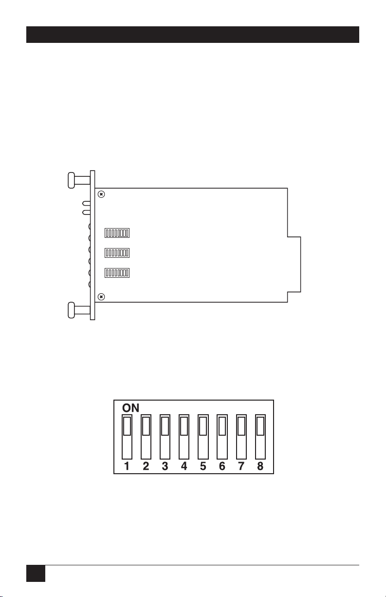
The mDSL Rack Card front card uses hardware switches for configuration. An
interface driver board strap and three eight-position DIP switches are positioned
on the bottom side of the front card (see Figure 3-1).
Figure 3-1. The mDSL Rack Card’s configuration switches.
Figure 3-2 shows the orientation of the DIP switches with respect to the ON and
OFF positions.
Figure 3-2. Close-up of configuration switches
(all switches are identical in appearance).
SW3
SW2
SW1
Page 12
11
CHAPTER 3: Configuration
3.1.1 R
EVERSIBLEINTERFACEDRIVERBOARD
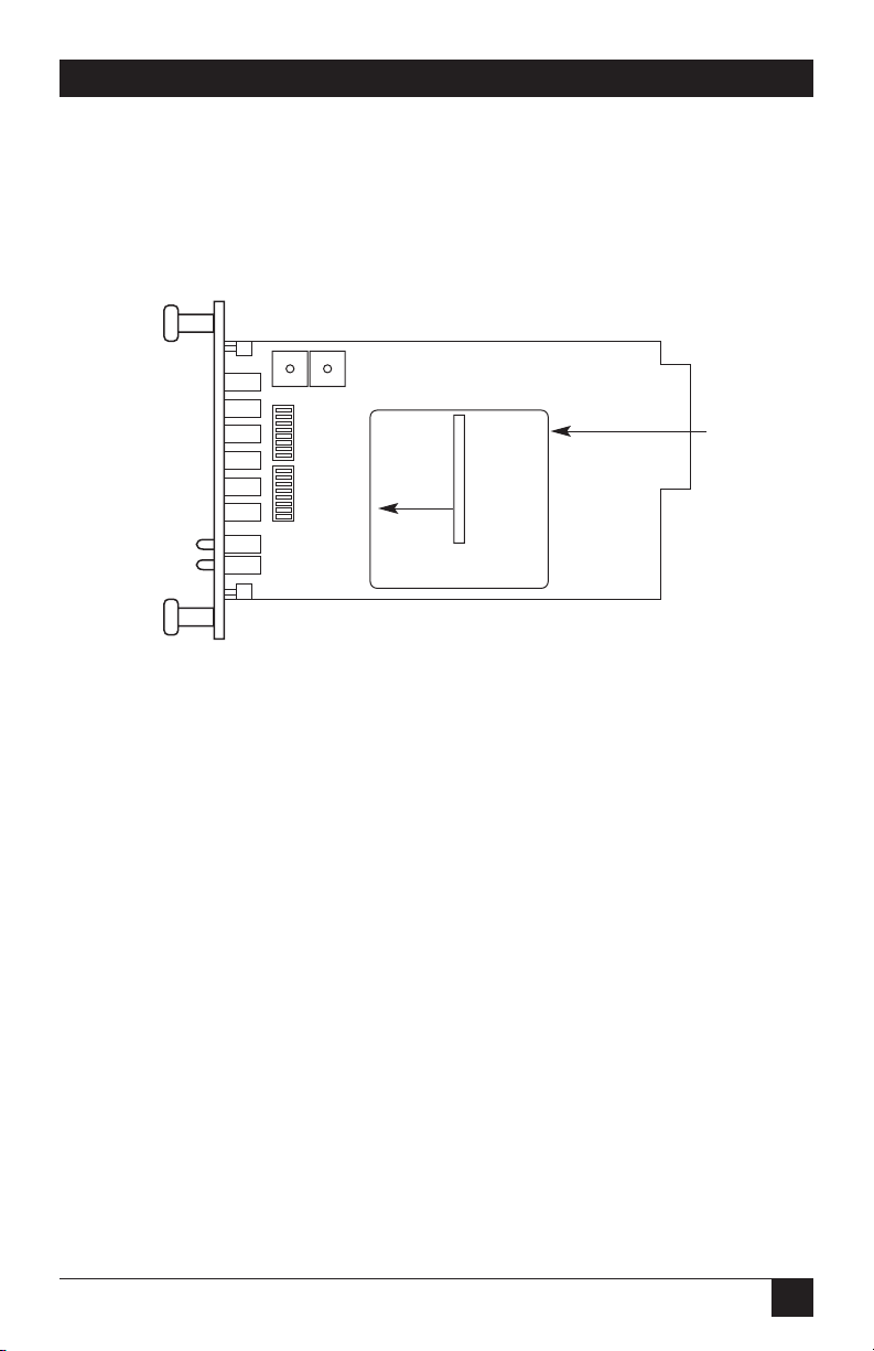
The mDSL Rack Card features switchable interface driver boards that allow a wide
range of DTE interface connections. Figure 3-3 shows the interface driver board on
the top of the mDSL Rack Card PC board.
Figure 3-3. Close-up of the interface driver board.
Follow the instructions below to select the correct interface for your application:
1. With the mDSL front card pulled out of the rack chassis, locate the driver
board on the top of the mDSL front card.
2. Lift the interface board gently off of the PC board.
3. Locate the correct interface on the bottom of the driver board. For example,
the RS-232/V.35 interface board is marked “THIS SIDE UP FOR RS-232” on
one side and “THIS SIDE UP FOR V.35” on the other side. Other “single”
interface boards are marked with “FRONT” on one side of the board.
4. Re-orient the interface board into the socket with the appropriate interface
pointed UP and with the arrow pointing toward the front panel of the mDSL
Rack Card PC board.
5. Push the interface driver board gently onto the socket and re-install into the
rack system.
THIS SIDE UP FOR V.35.
Interface
Driver
Board
FRONT
Page 13

12
HIGH-SPEED 2-WIRE SHORT-RANGE DSL LINE DRIVER RACK CARD
3.1.2 C
ONNECTING TO A
DTE D
EVICE
The serial port on most interface modules (all except the X.21 module) is hardwired as a DCE. Therefore these modules “want” to plug into a DTE such as a
terminal, PC, or host. When making the connection to your DTE device, use a
straight-through cable of the shortest possible length—we recommend 6 feet
(1.8 m) or less. When purchasing or constructing an interface cable, please refer to
the pin diagrams in Appendix A as a guide.
3.1.3 C
ONNECTING TO A
DCE D
EVICE
If the mDSL Rack Card interface module is hard-wired as a DCE (all except the
X.21 module), you must use a null-modem cable when connecting to a modem,
multiplexor, or other DCE device. This cable should be of the shortest possible
length—we recommend 6 feet (1.8 m) or less. When purchasing or constructing a
null-modem interface cable, use the pin diagrams in Appendix A as a guide.
NOTE
Pinout requirements for null-modem applications vary widely between
manufacturers. If you have any questions about a specific application,
call Black Box Technical Support at 724-746-5500.
3.1.4 C
ONFIGURING THE
X.21 I
NTERFACEMODULE
The serial port on the X.21 interface module is default wired as a DCE, but may be
switched to a DTE. This is done by reversing the orientation of the DCE/DTE
strap, as described below:
To reverse DCE/DTE orientation, remove the interface module according to the
instructions in Section 3.1.1. The DCE/DTE strap is located on the top side of the
interface module’s PC board. The arrows on the top of the strap indicate the
configuration of the X.21 port (for example, if the DCE arrows are pointing
toward the rear card connector, the X.21 port is wired as a DCE). Reverse the
DCE/DTE orientation by pulling the strap out of its socket, rotating it 180º, then
plugging the strap back into the socket. You will see that the DCE/DTE arrows now
point in the opposite directions, showing the new configuration of the X.21 port.
Reinstall the module according to the instructions in Section 3.1.1.
3.1.5 C
ONFIGURING
DIP-S
WITCHSET
S1
Switch S1 is used to set the address of the card in the SNMP Management Module.
When the mDSL Rack Card is installed with a SNMP Management Module, the
cards and their remote units can be SNMP managed using a standard Network
Management Station (NMS) or a standard Web browser (Netscape
®
Navigator or
Internet Explorer
®
). For more information about setting the address, refer to the
SNMP Management Module Users’ Manual (part number RM261C-SNMP).
Page 14

13
CHAPTER 3: Configuration
NOTE
If you are not using your mDSL Rack Card in a network-managed
environment, please set all S1 switches to the ON position.
3.1.6 C
ONFIGURING
DIP-S
WITCHSET
S2
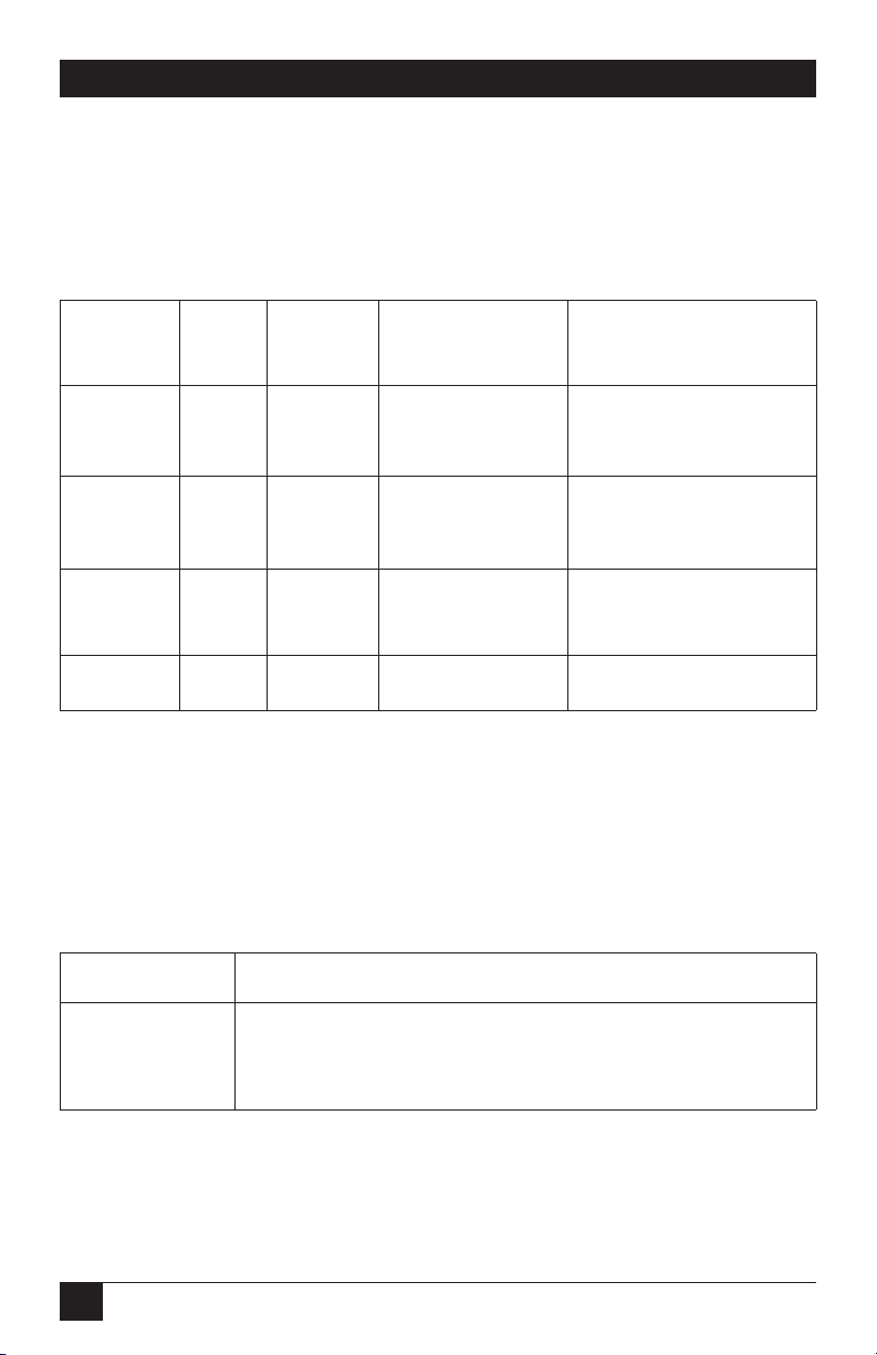
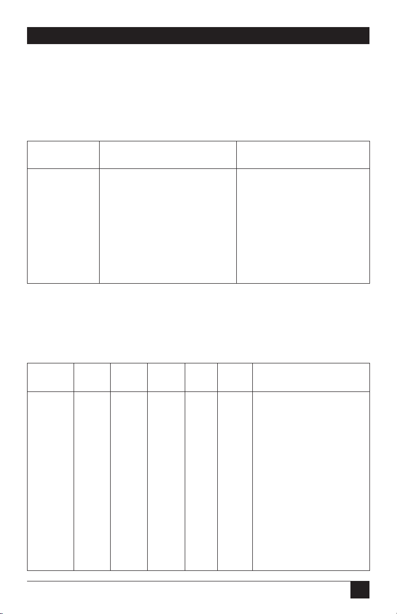
The configuration switches on S2 allow you to specify the clocking mode and
response to DTE loop enable. Default settings of S2 are shown in Table 3-1.
Table 3-1. S2 summary.
Position Function Factory Default
S2-1 Reserved Off
S2-2 Reserved Off
S2-3 Reserved Off
S2-4 Reserved Off
S2-5 Reserved Off
S2-6 Clock Mode On
S2-7 Clock Mode On
S2-8 Enable Loop from DTE Off Disable
Switches S2-1, S2-2, S2-3, S2-4, and S2-5: These switches are reserved for future use
and should remain in the OFF position.
}
Internal
Page 15
14
HIGH-SPEED 2-WIRE SHORT-RANGE DSL LINE DRIVER RACK CARD
Switches S2-6 and S2-7: Clock Mode
Use Switches S2-6 and S2-7 to configure the mDSL Rack Card for internal,
external, or receive recover clock mode.
Table 3-2. Clock mode.
CO/CP S2-6 S2-7 Clock Mode Description
Unit
CO On On Internal Transmit clock generated
internally
CO Off On External (DTE) Transmit clock derived
from the terminal interface
CP On Off Receive Recover Transmit clock derived
from the receive line
Off Off Reserved
Switch S2-8: Enable/Disable Loop Tests from DTE
Use Switch S2-8 to allow the mDSL Rack Card to enter loopback tests when the
DTE raises the appropriate loop request pin.
Table 3-3. Enable/disable loop tests.
S2-8 Setting
On Response to DTE Loopback Request Enabled
Off Response to DTE Loopback Request Disabled
Page 16
15
CHAPTER 3: Configuration
3.1.7 C
ONFIGURING
DIP-S
WITCHSET
S3
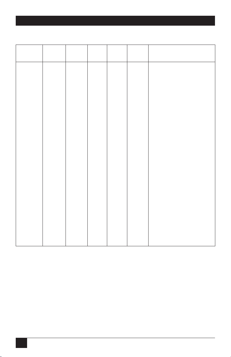
Use the eight DIP switches in Switch S3 to enable the DTE connection rate. The
following table summarizes default positions of DIP-Switch S3. Detailed
descriptions of each switch follow the table.
Table 3-4. S3 summary.
Position Function Factory Default
S3-1 DTE Rate On
S3-2 DTE Rate Off
S3-3 DTE Rate Off
S3-4 DTE Rate Off
S3-5 DTE Rate On
S3-6 DTE Rate On
S3-7 Reset Software Defaults On Normal operation
S3-8 Transmit Data Sample Point On Normal operation
Switch S3-1: DTE Rate
Use Switches S3-1 through S3-6 to set the rate-adaptive DTE bit rate.
Table 3-5. DTE bit rate.
S3-1 S3-2 S3-3 S3-4 S3-5 S3-6 DTE Rate (kbps)
Off Off On On On On 64
On On Off On On On 128
Off On Off On On On 192
On Off Off On On On 256
Off Off Off On On On 320
On On On Off On On 384
Off On On Off On On 448
On Off On Off On On 512
Off Off On Off On On 576
On On Off Off On On 640
Off On Off Off On On 704
On Off Off Off On On 768
Off Off Off Off On On 832
}
768 kbps
Page 17
16
HIGH-SPEED 2-WIRE SHORT-RANGE DSL LINE DRIVER RACK CARD
Table 3-5 (continued). DTE bit rate.
S3-1 S3-2 S3-3 S3-4 S3-5 S3-6 DTE Rate (kbps)
On On On On Off On 896
OffOnOnOnOffOn 960
On Off On On Off On 1024
Off Off On On Off On 1088
On On Off On Off On 1152
Off On Off On Off On 1216
On Off Off On Off On 1280
Off Off Off On Off On 1344
On On On Off Off On 1408
Off On On Off Off On 1472
On Off On Off Off On 1536
On On Off Off Off On 1600
Off On Off Off Off On 1664
On Off Off Off Off On 1728
Off Off Off Off Off On 1792
On On On On On Off 1856
Off On On On On Off 1920
On Off On On On Off 1984
Off Off On On On Off 2048
On On Off On On Off 2112
Off On Off On On Off 2176
On Off Off On On Off 2240
Off Off Off On On Off 2304
NOTE
The actual line rates of the line driver is determined by the selection of
the DTE rate. To see the line rate associated with various DTE rates,
refer to the distance chart in Appendix B.
Switch S3-7: Reset Software Defaults
Switch S3-7 allows the user to reset the software-configured factory defaults. This
will only be needed when using the SNMP Management Module (part number
RM261C-SNMP) to SNMP manage your units. For more information, please refer
to the SNMP Management Module Users’ Manual.
Page 18
17
CHAPTER 3: Configuration
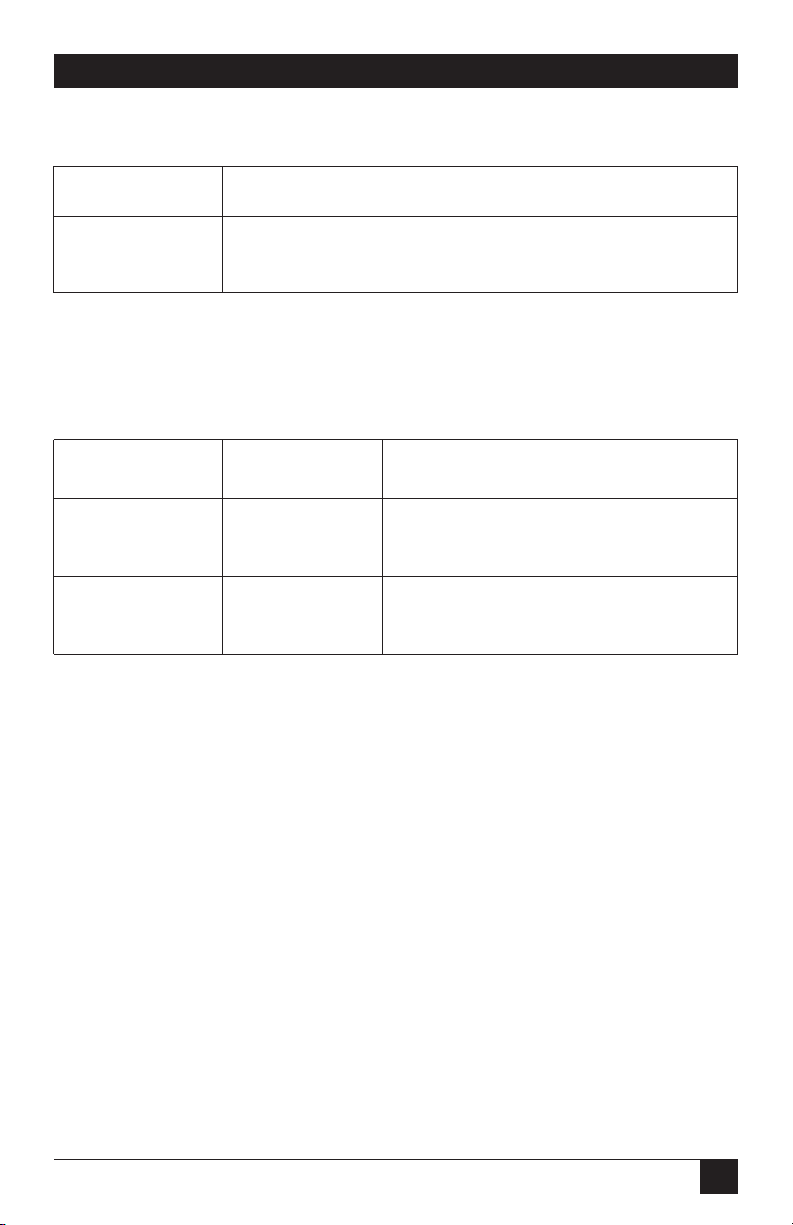
Table 3-6. Reset software defaults.
S3-7 Setting
On Normal Operation
Off Reset
Switch S3-8: Transmit Data (TD) Sampling Point
Table 3-7. Transmit data sampling point.
S3-8 Setting Description
On Normal TD sampled on the falling edge of the
mDSL Rack Card Transmit Clock (TC)
Off Invert TD sampled on the rising edge of the
mDSL Rack Card Transmit Clock
3.2 mDSL Rack Card Plug-and-Play
The mDSL Rack Card Plug-and-Play application allows ISPs and PTTs to quickly
upgrade the link speed for a customer without re-configuring the customer
premise (CP) unit (such as the ME0008A or ME0005A). It will also allow ISPs and
PTTs to set up all of the configurations at the central office (on the rack cards)
before installation of the standalone units, thus saving time spent configuring and
re-configuring DIP-switch settings.
The mDSL Rack Card Plug-and-Play feature allows you to configure the DTE rate
for the link from the rack card at the Central Office (CO). The standalone unit at
the Customer Premise (CP) site will automatically configure itself to the DTE rate
of the rack card. Other configuration parameters fall to the default state. This
allows changes in the configuration to be handled from a single end of the link.
When installing a CO/CP-style application, the local end of the link is comprised
of a CO unit (mDSL Rack Card) set to either internal or external clocking mode
and a CP unit (such as the ME0008A, ME0005A, or another ME0004C) set as a
Plug-and-Play unit. The Plug-and-Play CP standalone will have all of its DIP switches
set to the ON position (as indicated in Figure 3-4).
Page 19
18
HIGH-SPEED 2-WIRE SHORT-RANGE DSL LINE DRIVER RACK CARD
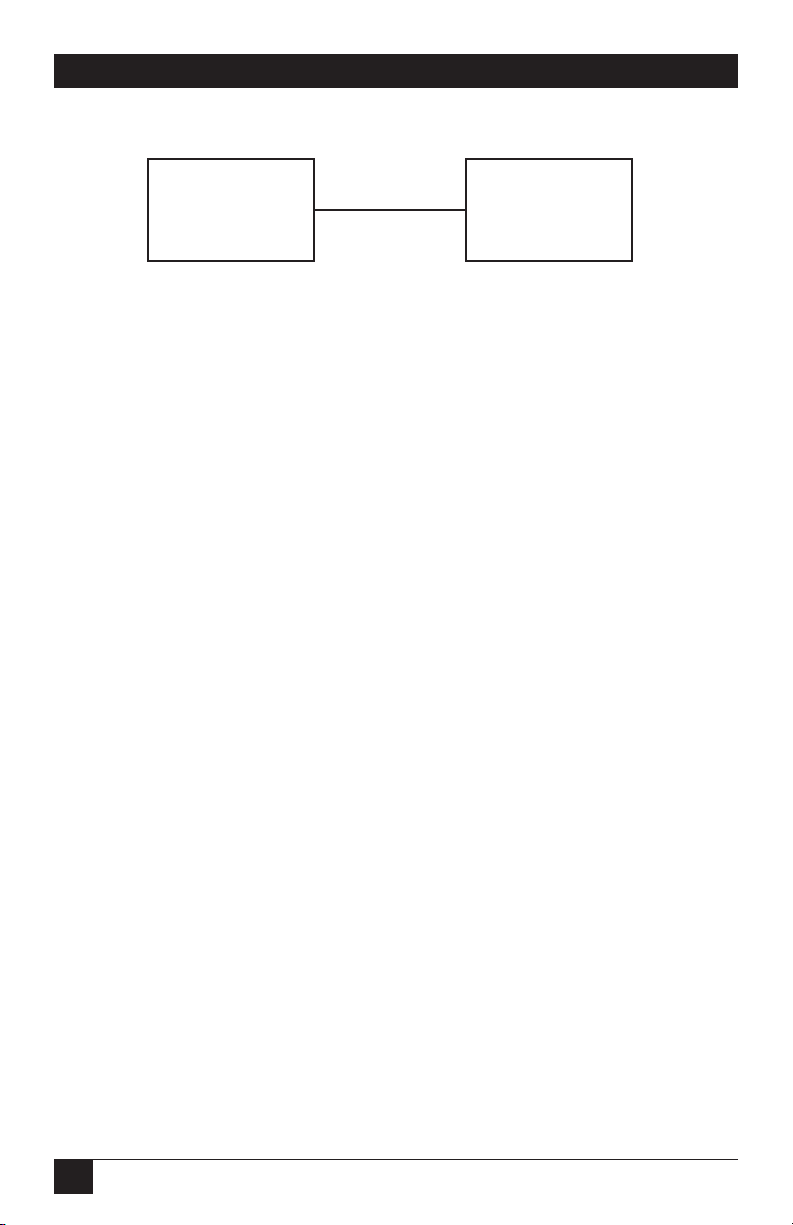
Figure 3-4. Typical Plug-and-Play application.
When the units are connected, the CP will come up with a predefined default
configuration (Receive Recovered clocking). During the handshaking process
between the units, the CO unit will set the DTE rate/line rate of the CP unit to
match its DIP-switch configuration settings. If the DTE rate for the link requires a
change, the change is needed only at the CO side of the link.
The mDSL Rack Card Plug-and-Play application will also work in the managed
system using the SNMP Management Module and mDSL Rack Cards installed in
the 2U rack system. In this application, the system administrator can configure the
entire rack through the Network Management Station (NMS) before the
standalone (CP) units are installed. For more information on the SNMP
management of your rack, please refer to the SNMP Management Module Operations
Manual.
3.3 Configuring the Rear Interface Cards
The mDSL Rack Card has five interface card options: 10BASE-T, G.703, RS-530,
V.35, and X.21. Each of these options supports one DTE interface connection and
one 2-wire line connection.
NOTE
The ME0004C rear cards are specifically designed to operate with the
ME0004C function card and must not be swapped with other function
cards.
Before installation, examine the rear card you have selected to be sure it is
properly configured for your application. Each rear card is configured by setting
straps located on the PC board. To configure the rear cards, set the configuration
straps. Figure 3-5 shows the orientation of these straps. Each strap can either be on
pegs 1 and 2 or on pegs 2 and 3.
mDSL Rack
Card (ME0004C)
(CO)
DIP switches configured
according to specific
application requirements.
DIP switches all in ON position.
mDSL Rack
Card (ME0004C)
(CP)
Page 20

19
CHAPTER 3: Configuration
Figure 3-5. Orientation of interface card straps.
Sections 3.3.1, 3.3.2, and 3.3.3 describe the strap locations and possible settings for
each rear card.
3.3.1 DB25 (RS-530
AND
V.24) R
EARCARDSTRAPSETTINGS
Figure 3-6 shows strap locations for the DB25 rear cards. These straps determine
various grounding characteristics for the terminal interface and twisted-pair lines.
JB3 and JB4 are user-configurable.
Figure 3-6. Strap locations.
JB3
JB4
Page 21

20
HIGH-SPEED 2-WIRE SHORT-RANGE DSL LINE DRIVER RACK CARD
Table 3-8 provides an overview of interface strap functions for the rear interface
cards. Following the table overview are detailed descriptions of each strap’s
function.
Table 3-8. Interface card strap summary.
Strap Function Position 1 and 2 Position 2 and 3
JB3 DTE Shield (Pin 1) and FRGND Connected Open*
JB4 FRGND and SGND Connected Open*
*Default setting
DTE Shield (DB25 Pin 1) and FRGND (JB3)
In the connected position, this strap links DB25 pin 1 and frame ground. In the
open position, pin 1 is disconnected from frame ground.
Table 3-9. DTE shield and FRGND.
JB3
Position 1 & 2 = DTE Shield (Pin 1) and FRGND connected
Position 2 & 3 = DTE Shield (Pin 1) and FRGND not connected
FRGND and SGND (JB4)
In the connected position, this strap links DB25 pin 7 (signal ground) and frame
ground through a 100-ohm resistor. In the open position, pin 7 is connected
directly to frame ground.
Table 3-10. FRGND and SGND.
JB4
Position 1 & 2 = SGND (Pin 7) and FRGND connected through a 100-ohm
resistor
Position 2 & 3 = SGND (Pin 7) and FRGND directly connected
Page 22

21
CHAPTER 3: Configuration
3.3.2 M/34 (V.35) R
EARCARDSTRAPSETTINGS
Figure 3-7 shows the strap location for the M/34 rear card. This strap determines
whether signal ground and frame ground will be connected.
Figure 3-7. Strap locations.
Table 3-11 provides an overview of interface strap functions for the rear interface
cards. Following the table overview are detailed descriptions of each strap’s
function.
Table 3-11. Interface card strap summary.
Strap Function Position 1 and 2 Position 2 and 3
JB3 DTE Shield (Pin A) Connected Open*
and FRGND
JB4 FRGND and Connected Open*
SGND (Pin B)
*Default setting
JB3
JB4
Page 23

22
HIGH-SPEED 2-WIRE SHORT-RANGE DSL LINE DRIVER RACK CARD
DTE Shield (M/34 Pin A) and FRGND (JB3)
In the connected position, this strap links M/34 pin A and frame ground. In the
open position, pin A is disconnected from frame ground.
Table 3-12. DTE shield and FRGND.
JB3
Position 1 & 2 = DTE Shield (Pin A) and FRGND connected
Position 2 & 3 = DTE Shield (Pin A) and FRGND not connected
FRGND and SGND (JB4)
In the connected position, this strap links signal ground and frame ground
through a 100-ohm resistor. In the open position, signal ground is disconnected
from frame ground.
Table 3-13. FRGND and SGND.
JB4
Position 1 & 2 = FRGND and SGND connected
Position 2 & 3 = FRGND and SGND not connected
3.3.3 DB15 (X.21) R
EARCARDSTRAPSETTINGS
Figure 3-8 shows strap locations for the DB15 rear cards. These straps determine
various grounding characteristics for the terminal interface and twisted-pair lines.
JB3 and JB4 are user-configurable.
Page 24

23
CHAPTER 3: Configuration
Figure 3-8. Strap locations.
Table 3-14 provides an overview of interface strap functions for the rear interface
cards. Following the table overview are detailed descriptions of each strap’s
function.
Table 3-14. Interface card strap summary.
Strap Function Position 1 and 2 Position 2 and 3
JB3 DTE Shield (Pin 1) Connected Open
and FRGND
JB4 FRGND and Connected Open*
SGND (Pin 8)
JB3
JB4
Page 25

24
HIGH-SPEED 2-WIRE SHORT-RANGE DSL LINE DRIVER RACK CARD
DTE Shield (DB15 Pin 1) and FRGND (JB3)
In the connected position, this strap links DB15 pin 1 and frame ground. In the
open position, pin 1 is disconnected from frame ground.
Table 3-15. DTE shield and FRGND.
JB3
Position 1 & 2 = DTE Shield (Pin 1) and FRGND connected
Position 2 & 3 = DTE Shield (Pin 1) and FRGND not connected
FRGND and SGND (JB4)
In the connected position, this strap links DB15 pin 8 (signal ground) and frame
ground through a 100-ohm resistor. In the open position, pin 8 is connected
directly to frame ground.
Table 3-16. FRGND and SGND.
JB4
Position 1 & 2 = SGND (Pin 8) and FRGND connected through a 100-ohm
resistor
Position 2 & 3 = SGND (Pin 8) and FRGND directly connected
Page 26

25
CHAPTER 3: Configuration
Installing the X.21 Daughterboard onto the X.21 Line Driver Card
Figure 3-9 shows the X.21 daughterboard, DCE/DTE selector, and jumper (JP1)
location with respect to the rack card. Following Figure 3-9 are guidelines for the
installation of the X.21 daughterboard, setting for DCE/DTE, and a brief
description of Jumper JP1.
Figure 3-9. View of the X.21 daughterboard, DCE/DTE selector, and JP1.
Follow the steps below for proper installation of the X.21 daughterboard.
WARNING
The X.21 daughterboard connector is not keyed and can be installed
incorrectly.
1. On the top side of the X.21 daughterboard, locate the designator shown:
Front X.21
2. Install the X.21 daughterboard onto the front card with the “Front X.21”
arrow pointing to the front panel of the rack card (see Figure 3-9).
Rack Card
DCE/DTE
selector
X.21 Daughterboard
Front panel
Rear
JP1
Page 27

26
HIGH-SPEED 2-WIRE SHORT-RANGE DSL LINE DRIVER RACK CARD
DCE/DTE Selector for the X.21 Daughterboard
The X.21 daughterboard can be set up as a DCE (default) or DTE device. The
DCE/DTE selector must be installed in the X.21 daughterboard for any
configuration. The following information describes the setting for DCE/DTE.
• DCE setting (default): To set a rack card as a DCE device, install the
DCE/DTE selector with the DCE arrows pointing toward the front panel.
• DTE setting: To set a rack card as a DTE device, install the DCE/DTE selector
with the DTE arrows pointing toward the front panel.
Jumper (JP1) Setting
The X.21 daughterboard operates at speeds up to 2.3 Mbps. When using the
daughterboard at data rates of 2 Mbps or higher, clocking issues may introduce bit
errors. Bit errors can also occur when long cables are used to interconnect the
modem to an X.21 terminal device (router, multiplexor, etc.). To solve bit error
problems due to speed and/or long cables, the X.21 daughterboard is equipped
with a jumper selector (JP1) that changes the sampling edge of the transmit clock.
Refer to Figure 3-9 for jumper JP1 location.
The following is a brief description of JP1 setting and function.
• Normal setting: The jumper shorts the two outer pins of JP1. Figure 3-9 shows
the default position. This position is selected when operating at low data rate
(less than 2 Mbps) and using a short X.21 terminal cable.
• Invert setting: The jumper shorts the two inner pins of JP1. This setting is
selected when operating at data rates of 2 Mbps or higher or when using long
X.21 terminal cables.
NOTE
The G.703/G.704 Rear Card module is covered in Appendix D. The
10BASE-T Ethernet Rear Card module is covered in Appendix E.
Page 28

27
CHAPTER 4: Installation
4. Installation
This chapter describes the functions of the rack chassis, explains installation of
front and rear mDSL Rack Cards into the chassis, and explains how to connect to
the twisted-pair interface and the serial interface.
4.1 The Rack Chassis
The rack chassis (Figure 4-1) has fourteen short-range modem card slots, plus its
own power supply. Measuring only 3.5" high, the rack is designed to occupy only
2U in a 19" rack. Sturdy front handles allow the rack chassis to be extracted and
transported conveniently.
Figure 4-1. The rack chassis.
THER
ACKPOWERSUPPLY
The power supply included in the rack uses the same mid-plane architecture as the
modem cards. The front card of the power supply slides in from the front, and the
rear card slides in from the rear. They plug into one another in the middle of the
rack. The front card is then secured by thumbscrews, and the rear card by
conventional metal screws.
WARNING
There are no user-serviceable parts in the power-supply section of the
rack chassis. Voltage-setting changes and fuse replacement should
only be performed by qualified service personnel. Contact Black Box
Technical Support at 724-746-5500 for details.
Page 29

28
HIGH-SPEED 2-WIRE SHORT-RANGE DSL LINE DRIVER RACK CARD
Powering Up Your Rack
The power supplies that come with your rack system are equipped with a powerentry connector on the rear card. The power supplies are hot-swappable, so you
are not required to remove the cards from the rack while applying power to the
system.
The power switch is located on the front panel. When plugged in and switched on,
a red front-panel LED will glow. Since the rack chassis is a “hot-swappable” rack, it
is not necessary for any cards to be installed before switching on the power supply.
The power supply may be switched off at any time without harming the installed
cards.
4.2 Installing the mDSL Rack Card into the Chassis
The mDSL Rack Card is composed of a front card and a rear card. The two cards
meet inside the rack chassis and plug into each other by way of mating 50-pin cardedge connectors. Use the following steps as a guideline for installing each mDSL
Rack Card into the rack chassis:
1. Slide the rear card into the back of the chassis along the metal rails provided.
2. Secure the rear card using the metal screws provided.
3. Slide the front card into the front of the chassis. It should meet the rear card
when it’s almost all the way into the chassis.
4. Push the front card gently into the card-edge receptacle of the rear card. It
should “click” into place.
5. Secure the front card using the thumbscrews.
Page 30
29
CHAPTER 4: Installation
4.3 Wiring the mDSL Rack Card
Each of the rear interface cards compatible with the mDSL Rack Card has one
terminal interface port and one 2-wire (twisted-pair) port. For specific interface
pinouts, refer to the diagrams in Appendix A.
4.3.1 C
ONNECTION TO THETWISTED-PAIRINTERFACE
The mDSL Rack Card supports communication between two DTE devices at
distances to 5 miles (8 km) over 24-AWG (0.5-mm) twisted-pair wire. There are two
essential requirements for installing the mDSL Rack Card:
1. These units work in pairs. Therefore, you must have one mDSL Rack Card (or
a compatible model) at each end of a single twisted-pair interface.
2. To function properly, the mDSL Rack Card needs one twisted pair of metallic
wire. This twisted pair must be unconditioned, dry, metallic wire, between 19
(0.9 mm) and 26 AWG (0.4 mm); the higher-number gauges may limit
distance some what. Standard dial-up telephone circuits, or leased circuits
that run through signal-equalization equipment, or standard, flat modular
telephone-type cable are not acceptable.
4.3.2 TWO-W
IRECABLECONNECTION VIA
RJ-45
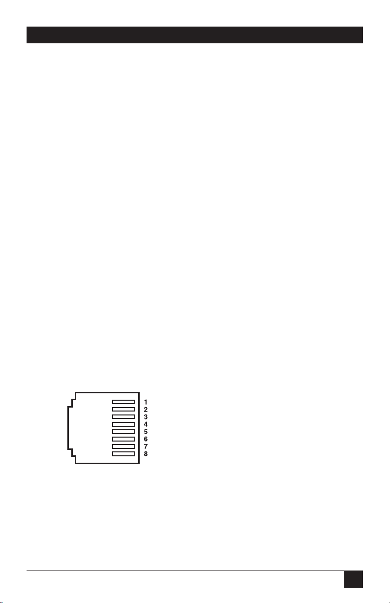
The RJ-45 connector on the mDSL Rack Card’s twisted-pair interface is polarity
insensitive and is wired for a two-wire interface.The signal/pin relationships are
shown in Figure 4-2.
Figure 4-2. Twisted-pair line interface.
- - - - - - - - - - - - - - - - - - - - - - - - 1 (N/C)
- - - - - - - - - - - - - - - - - - - - - - - - 2 (N/C)
- - - - - - - - - - - - - - - - - - - - - - - - 3 (N/C)
- - - - - - - - - - - - - - - - - - - - - - - - 4 (Tip)
- - - - - - - - - - - - - - - - - - - - - - - - 5 (Ring)
- - - - - - - - - - - - - - - - - - - - - - - - 6 (N/C)
- - - - - - - - - - - - - - - - - - - - - - - - 7 (N/C)
- - - - - - - - - - - - - - - - - - - - - - - - 8 (N/C)
Page 31
30
HIGH-SPEED 2-WIRE SHORT-RANGE DSL LINE DRIVER RACK CARD
5. Operation
Once the mDSL Rack Card is properly configured and installed, it should operate
transparently. This chapter describes functions of the LED status indicators and
the use of the built-in loopback test modes.
5.1 LED Status Indicators
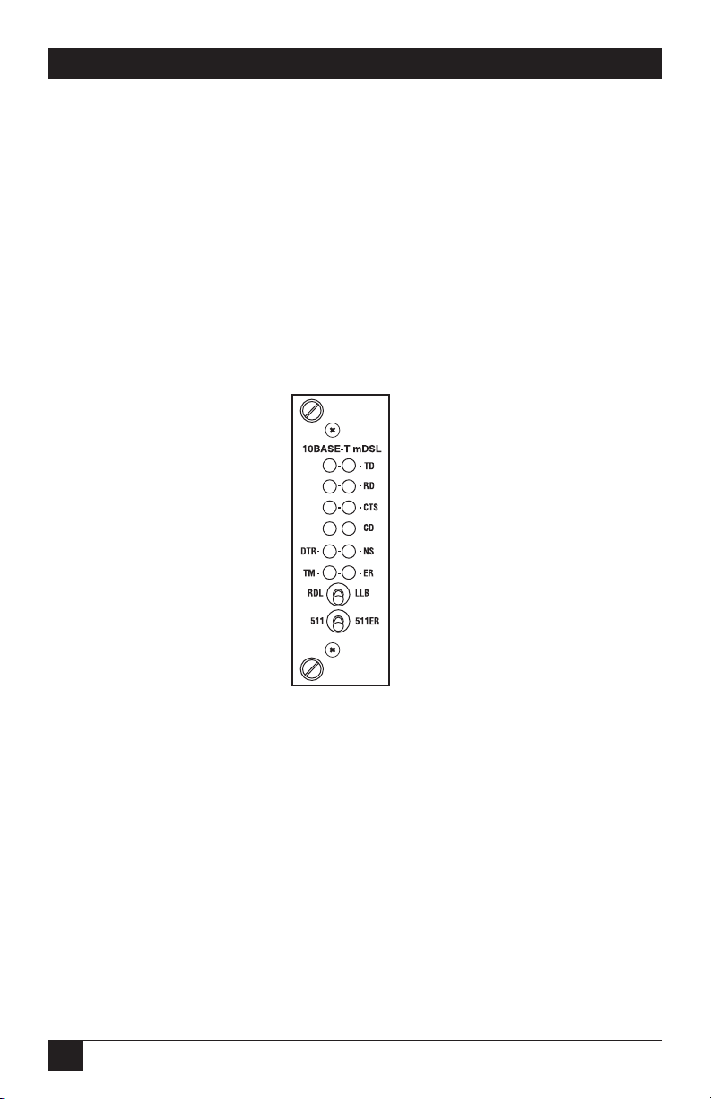
The mDSL Rack Card features twelve front-panel LEDs that monitor power, the
DTE signals, network connection, and test modes. Figure 5-1 shows the location of
each LED. Following Figure 5-1 is a description of each LED’s function.
Figure 5-1. Front-panel LEDs.
• TD and RD: Glows yellow to indicate an idle condition of Binary “1” data on
the respective terminal interface signals. Green indicates Binary “0” data.
• CTS: Consists of two LEDs (one yellow, one green). CTS glows green to
indicate that the Clear to Send signal from the modem is active. Yellow
indicates inactive CTS.
• CD: Consists of two LEDs (one yellow, one green). CD glows yellow if no
carrier signal is being received from the remote modem. Green indicates that
the remote modem’s carrier is being received.
• DTR: Glows green to indicate that the Data Terminal Ready signal from the
terminal is active.
Page 32

31
CHAPTER 5: Operation
• ER: Blinks ON/OFF after a 511/511E test has timed out. See Section 5.2.4 for
more information.
Flashes once to indicate that a CRC error has occurred (during normal
operation) or bit errors have occurred (during 511/511E test).
Only at power up, blinks once every 200 ms if the DTE rate is set to an
unsupported setting.
• TM: Glows yellow to indicate that the mDSL Rack Card has been placed in test
mode. The unit can be placed in test mode by the local user or by the remote
user. The TM LED will flash for 400 msec when a valid packet is received from
the SNMP Management Module.
• NS: (No Signal) glows red to indicate that the local mDSL Rack Card is not
connected with the remote mDSL Rack Card. The TM LED will flash for 400
msec when a valid packet is received from the SNMP Management Module.
5.2 Test Modes
The mDSL Rack Card offers two proprietary loopback test modes, plus a built-in
V.52 BER test-pattern generator to evaluate the condition of the modems and the
communication link. These tests can be activated physically from the front panel or
via the interface.
5.2.1 O
VERVIEW
Figure 5-2 shows the major elements used in the loopback and pattern tests
available in the mDSL Rack Card. Each block has several functions. Following
Figure 5-2 are descriptions that show how the elements are used during test modes.
Figure 5-2. Major elements used in the loopback and pattern tests.
Framer
Processor Processor
Framer
Pattern
Gen./Det.
Pattern
Gen./Det.
Loop
Control
Loop
Control
Line
Page 33

32
HIGH-SPEED 2-WIRE SHORT-RANGE DSL LINE DRIVER RACK CARD
• Framer: The framer is used to determine the status of the line. In normal
operation, the framer transmits and expects to receive framed packets from
the far end. If the framer receives framed packets from the far end, CTS and
CD will be active. If framed packets are not received, CTS and CD will be
inactive. The restart procedure uses this information to determine if a valid
connection is made (cable disconnect, poor cable quality, etc). In normal Data
Mode, if the box receives four seconds of unframed packets, it will restart the
box and begin trying to re-establish a connection with the far end. The
distinction between framed packets and unframed packets becomes important
when we discuss the pattern generator.
• Pattern Gen./Det.: This part of the processor generates and detects the
511/511E patterns. When transmitting 511 patterns, the information is
unframed (because it originates after the framer) and is intended to be
evaluated only by another processor. If the units are in Data Mode and the
pattern generator is enabled on one end of the link, the far end will begin
receiving unframed packets and assume that the line has gone down. During
test modes, we force the pattern generator to time out before it can cause the
link to be killed.
• Loop Control: This part of the processor is used to control loopbacks. In a
Local Loop, the data is looped back towards the local DTE. In a Remote Loop,
the data is looped back to the line, but it is also allowed to pass through to the
framer and to the remote DTE.
5.2.2 R
ESTARTPROCEDURE ANDTIMEOUTS
The restart procedure is in place to allow the units to re-establish a connection
after the framer begins seeing unframed packets. The Test Mode timing chart on
the next page shows the amount of time the framer must see consecutive
unframed packets before the unit will restart and try to establish a new line
connection. The reason that there are different Restart Times will become
apparent after reading the rest of the document. The 511/511E timeout shown
refers to the amount of time the 511/511E pattern will be valid. At the end of this
time, the pattern will automatically turn itself off and the normal data path will be
re-established. The ER LED will flash, indicating to the user that the test has timed
out. The ER LED will stop flashing once the 511/511E switch is placed into the
normal position.
Page 34

33
CHAPTER 5: Operation
Table 5-1. Test mode timing.
Item Elapsed Time (seconds)
Startup 50
Data Mode 4
511/511E Generator Enabled 60 (The generator will stop after 45
seconds.)
Remote End of an RDL 60
511/511E Timeout 45 (The pattern generator will
automatically turn off after 45 seconds.
The ER LED will flash until you turn off
the 511/511E switch.)
Symbol Indicators
This symbol designates the origination or the termination of a data path. The
direction of the arrow connected distinguishes the two data paths.
This symbol designates an invalid data path. If there is data present, it should
be ignored.
5.2.3 L
OOPS ANDPATTERNS
The following section describes the test modes used in the mDSL Rack Card. At
the bottom of each test mode, a figure is included to show the data path.
Local Loop
There are two different modes of operation for a local loop, depending on the
status of the units at the time that the local loop is initiated. If the units are not
linked (NS LED on) and the local loop is initiated either by the front-panel switch
or the DTE interface, the unit will enter mode 1. If the units are linked, NS LED
off, then the unit will enter a mode 2 local loop.
A mode 1 local loop is shown in Figure 5-3. When the local loop is initiated, either
by the front-panel switch or the DTE interface, the loop will be activated within the
local DSP (Digital Signal Processor). The data present at the local DTE interface
X
Page 35
34
HIGH-SPEED 2-WIRE SHORT-RANGE DSL LINE DRIVER RACK CARD
will be looped back to the local DTE by the loop control block within the
processor. Any data present on the line or at the far-end DTE interface is invalid.
The remote unit will remain in the startup mode, NS LED off, CTS LED yellow,
and CD LED yellow, until the local unit is taken out of the local loop mode. After
the local loop is deselected, the units will both be in startup mode and the link will
be established.
Figure 5-3. Local loop mode 1.
A mode 2 local loop is shown in Figure 5-4. When the local loop is initiated, either
by the front-panel switch or the DTE interface, two separate loop paths will be
started. In the first path, data presented to the local DTE interface will be looped
back to the local DTE within the framer. In the second path, data presented at the
far-end DTE will be transmitted to the local DTE, then looped back within the
local DTE loop control block with the processor. After the local loop is deselected,
the units will be placed back into data mode and the normal data paths will be reestablished.
Figure 5-4. Local loop mode 2.
Framer
Processor
Processor
Framer
Pattern
Gen./Det.
Pattern
Gen./Det.
Loop
Control
Loop
Control
Line
X
X
X
X
Framer
Processor
Processor
Framer
Pattern
Gen./Det.
Pattern
Gen./Det.
Loop
Control
Loop
Control
Line
Page 36

35
Local Loop with 511/511E
When the unit is placed into a mode 1 local loop and the 511/511E pattern
generator is activated, the local pattern generator begins sending out a 511/511E
pattern to the loop control block. The loop control block will loop this data back
to the 511/511E pattern detector block, which will evaluate the data for errors.
Because the 511/511E pattern generator is contained within the processor, the
data is unframed, so the framer will begin seeing unframed packets. The framer
receives this unframed data and cannot distinguish this information from a line
disconnection (this would cause the unit’s restart procedure to start). What we
have done to allow this mode to work is to add timeouts for the pattern generators.
When the 511/511E is initiated, the line-restart procedure is changed to one
minute. The 511/511E pattern will timeout after 45 seconds. So if the 511/511E is
turned on during a local loop, the restart procedure is set to one minute, but the
511/511E pattern will timeout after 45 seconds, allowing the framer to begin
seeing framed packets (and not restart the box). After the 511/511E pattern times
out, the ER LED will begin flashing.
It will remain this way until the pattern-generator switch is turned off. Note that the
data at the local DTE and the remote DTE are not valid. Because the data is
unframed, there is no way for the framer to send this data out to the DTE. This is
an important distinction because other Black Box units will send out the 511
pattern.
Figure 5-5. Local loop mode 1 with 511/511E.
When the unit is placed into a mode 2 local loop, the 511/511E pattern generator
on the local unit is unavailable for transmission. As shown in Figure 5-6, the
511/511E pattern generator has no data path connections available. The
511/511E pattern generator is still available on the remote unit. For more
information on the proper operation of this pattern generator, please refer to the
Remote Digital Loop with 511/511E section.
CHAPTER 5: Operation
Framer
Processor
Processor
Framer
Pattern
Gen./Det.
Pattern
Gen./Det.
Loop
Control
Loop
Control
Line
X
X
X
X
X
X
Page 37

36
HIGH-SPEED 2-WIRE SHORT-RANGE DSL LINE DRIVER RACK CARD
Figure 5-6. Local loop mode 2 with 511/511E.
Remote Digital Loop
The remote loop uses the EOC channel (an out-of-band signaling channel) to
establish the remote link. Upon the RDL switch being thrown or DTE initiation, a
RDL_ON request signal is sent to the remote unit. The remote unit then responds
with an RDL acknowledge command, and the link is established. Data originates at
the local DTE and is looped at the remote DSP back to the local DTE. Note that
the data is also passed through to the remote DTE and is not squelched. When a
remote unit enters RDL, it changes its restart timeout to one minute (the reason
will be explained in the RDL with 511/511E section). If the line is disconnected, the
local unit will restart (NS LED activated) after 4 to 6 seconds, but the remote unit
will wait for one minute before it restarts. Note that the transmit data at the remote
DTE is ignored. When the switch is thrown or the DTE removes the RDL request,
the local unit will transmit an RDL_OFF request to the remote unit. The local unit
will keep its TM LED active until this request has been completely sent out. If the
switch is thrown again before the completion of the termination phase, the switch
will be ignored until it is placed back into the normal position.
Figure 5-7. Remote loop.
Framer
Processor
Processor
Framer
Pattern
Gen./Det.
Pattern
Gen./Det.
Loop
Control
Loop
Control
Line
X
X
Framer
Processor
Processor
Framer
Pattern
Gen./Det.
Pattern
Gen./Det.
Loop
Control
Loop
Control
Line
X
Page 38

37
CHAPTER 5: Operation
Remote Digital Loop with 511/511E
The Remote Digital Loop with 511/511E is shown below. After RDL is established,
the remote unit’s restart timer is set to one minute. This is because when the
511/511E generator is started on the local unit, the remote framer begins seeing
unframed packets. The remote unit cannot distinguish the 511/511E pattern from
the line being disconnected, so the restart timer has been lengthened to allow the
pattern generator to function. Once the 511/511E test is started, the local unit
changes its restart timer to one minute. The pattern originates within the DSP and
is sent to the remote unit. It is then looped back to the local unit where it is
evaluated for errors. After 45 seconds, the pattern generator will timeout and stops
sending the pattern. The ER LED will begin blinking until the user turns off the
511/511E switch.
Figure 5-8. Remote loop with 511/511E.
Data Mode with 511/511E Pattern Generators
When the units enter Data Mode, you can turn on the 511/511E pattern
generators on both ends of the link. Once a 511/511E pattern is selected on one
end of the link, the pattern generator will begin transmitting unframed 511/511E
through the line to the remote end. A possible problem with this test can occur
due to the restart procedure. Once the local 511/511E is turned on, the remote
unit begins receiving an unframed 511 pattern. If the remote unit does not turn on
the 511/511E pattern generator within four seconds, the remote unit will restart
and enter the startup mode. Note that once the 511/511E pattern generator is
started, the restart timer is changed to one minute (only on the unit which has the
pattern enabled). If both units enable the 511/511E pattern within four seconds of
each other, both units will be transmitting and receiving the 511/511E pattern.
Both framers are now receiving unframed data and will restart after one minute.
The 511/511E pattern generators will timeout after 45 seconds, re-enabling the
normal data path. The ER LED will begin flashing until the user terminates the
test.
Framer
Processor
Processor
Framer
Pattern
Gen./Det.
Pattern
Gen./Det.
Loop
Control
Loop
Control
Line
X
X
X
X
Page 39

38
HIGH-SPEED 2-WIRE SHORT-RANGE DSL LINE DRIVER RACK CARD
Figure 5-9. Data mode with 511/511E.
5.2.4 U
SING THE
V.52 (BER) T
EST-PATTERNGENERATOR
To use the V.52 BER tests in conjunction with the Remote Digital Loopback tests
(or with Local Line Loopback tests), follow these instructions:
1. Locate the 511/511E toggle switch on the mDSL Rack Card’s front panel and
move it to the left. This activates the V.52 BER test mode and transmits a 511
test pattern into the loop. If any errors are present, the local modem’s red ER
LED will blink sporadically.
2. If the above test indicates that no errors are present, move the V.52 toggle
switch to the right, activating the 511E test with errors present. If the test is
working properly, the local modem’s red ER LED will glow. A successful 511E
test will confirm that the link is in place, and that the mDSL Rack Card’s builtin 511 generator and detector are working properly.
NOTE
The V.52 BER tests can be used independently of the Remote Digital
Loopback tests. This requires two operators: (one) to initiate and
monitor the tests at the local mDSL Rack Card, and (one) to do the same
at the remote mDSL Rack Card. In this case, the test pattern sent by
each Rack Card will not be looped back, but will be transmitted down
the line to the other mDSL Rack Card.
Framer
Processor
Processor
Framer
Pattern
Gen./Det.
Pattern
Gen./Det.
Loop
Control
Loop
Control
Line
X
X
X
X
Page 40

39
APPENDIX A: Terminal Interface Pin Assignments
Appendix A. Terminal Interface Pin
Assignments
Table A-1. V.35 interface pin assignments,
M/34 female connector (DCE configuration).
Pin # Signal
B- - - - - - - - - - - - - - - - - - - - - - - - - SGND (Signal Ground)
C- - - - - - - - - - - - - - - - - - - - - - - - - RTS (Request to Send)
D- - - - - - - - - - - - - - - - - - - - - - - - - CTS (Clear to Send)
E- - - - - - - - - - - - - - - - - - - - - - - - - DSR (Data Set Ready)
F - - - - - - - - - - - - - - - - - - - - - - - - - CD (Carrier Detect)
H- - - - - - - - - - - - - - - - - - - - - - - - - DTR (Data Terminal Ready)
L - - - - - - - - - - - - - - - - - - - - - - - - - LLB (Local Line Loop)
M - - - - - - - - - - - - - - - - - - - - - - - - TM (Test Mode)
N- - - - - - - - - - - - - - - - - - - - - - - - - RDL (Remote Digital Loop)
P- - - - - - - - - - - - - - - - - - - - - - - - - TD (Transmit Data-A)
R- - - - - - - - - - - - - - - - - - - - - - - - - RD (Receive Data-A)
S- - - - - - - - - - - - - - - - - - - - - - - - - TD/ (Transmit Data-B)
T - - - - - - - - - - - - - - - - - - - - - - - - - RD/ (Receive Data-B)
U- - - - - - - - - - - - - - - - - - - - - - - - - XTC (External Transmit Clock-A)
V- - - - - - - - - - - - - - - - - - - - - - - - - RC (Receive Timing-A)
W - - - - - - - - - - - - - - - - - - - - - - - - XTC/ (External Transmit Clock-B)
X- - - - - - - - - - - - - - - - - - - - - - - - - RC/ (Receive Timing-B)
Y- - - - - - - - - - - - - - - - - - - - - - - - - TC (Transmit Clock-A)
AA- - - - - - - - - - - - - - - - - - - - - - - - TC/ (Transmit Clock-B)
Page 41

40
HIGH-SPEED 2-WIRE SHORT-RANGE DSL LINE DRIVER RACK CARD
Table A-2. RS-232, RS-530 interface pin assignments,
DB25 female connector (DCE configuration).
Pin # Signal
1 - - - - - - - - - - - - - - - - - - - - - - - - - FG (Frame Ground)
2 - - - - - - - - - - - - - - - - - - - - - - - - - TD (Transmit Data-A)
3 - - - - - - - - - - - - - - - - - - - - - - - - - RD (Receive Data-A)
4 - - - - - - - - - - - - - - - - - - - - - - - - - RTS (Request to Send-A)
5 - - - - - - - - - - - - - - - - - - - - - - - - - CTS (Clear to Send-A)
6 - - - - - - - - - - - - - - - - - - - - - - - - - DSR (Data Set Ready-A)
7 - - - - - - - - - - - - - - - - - - - - - - - - - SGND (Signal Ground)
8 - - - - - - - - - - - - - - - - - - - - - - - - - CD (Carrier Detect-A)
9 - - - - - - - - - - - - - - - - - - - - - - - - - RC/ (Receive Timing-B)
10 - - - - - - - - - - - - - - - - - - - - - - - - CD/ (Carrier Detect-B)
11 - - - - - - - - - - - - - - - - - - - - - - - - XTC/ (External Transmit Clock-B)
12 - - - - - - - - - - - - - - - - - - - - - - - - TC/ (Test Control-B)
13 - - - - - - - - - - - - - - - - - - - - - - - - CTS/ (Clear to Send-B)
14 - - - - - - - - - - - - - - - - - - - - - - - - TD/ (Transmit Data-B)
15 - - - - - - - - - - - - - - - - - - - - - - - - TC (Test Control)
16 - - - - - - - - - - - - - - - - - - - - - - - - RD (Receive Data-A)
17 - - - - - - - - - - - - - - - - - - - - - - - - RC (Receive Timing-A)
18 - - - - - - - - - - - - - - - - - - - - - - - - LLB (Local Line Loop)
19 - - - - - - - - - - - - - - - - - - - - - - - - RTS/ (Request to Send-B)
20 - - - - - - - - - - - - - - - - - - - - - - - - DTR (Data Transfer Rate-A)
21 - - - - - - - - - - - - - - - - - - - - - - - - DL (Remote Digital Loop)
22 - - - - - - - - - - - - - - - - - - - - - - - - DSR/ (Data Set Ready-B)
23 - - - - - - - - - - - - - - - - - - - - - - - - DTR/ (Data Transfer Rate-B)
24 - - - - - - - - - - - - - - - - - - - - - - - - XTC (External Transmit Clock-A)
25 - - - - - - - - - - - - - - - - - - - - - - - - TM (Test Mode)
Page 42

41
APPENDIX A: Terminal Interface Pin Assignments
Table A-3. X.21 interface pin assignments,
DB15 female connector (DTE /DCE configuration).
Pin # Signal
1 - - - - - - - - - - - - - - - - - - - - - - - - - Frame Ground
2 - - - - - - - - - - - - - - - - - - - - - - - - - T (Transmit Data-A)
3 - - - - - - - - - - - - - - - - - - - - - - - - - C (Control-A)
4 - - - - - - - - - - - - - - - - - - - - - - - - - R (Receive Data-A)
5 - - - - - - - - - - - - - - - - - - - - - - - - - I (Indication-A)
6 - - - - - - - - - - - - - - - - - - - - - - - - - S (Signal Element Timing-A)
7 - - - - - - - - - - - - - - - - - - - - - - - - - BT (Byte Timing-A, Not Used)
8 - - - - - - - - - - - - - - - - - - - - - - - - - SGND (Signal Ground)
9 - - - - - - - - - - - - - - - - - - - - - - - - - T/ (Transmit Data-B)
10 - - - - - - - - - - - - - - - - - - - - - - - - C/ (Control-B)
11 - - - - - - - - - - - - - - - - - - - - - - - - R/ (Receive Data-B)
12 - - - - - - - - - - - - - - - - - - - - - - - - I/ (Indication-B)
13 - - - - - - - - - - - - - - - - - - - - - - - - S/ (Signal Element Timing-B)
14 - - - - - - - - - - - - - - - - - - - - - - - - BT/ (Byte Timing-B, Not Used)
Page 43

42
HIGH-SPEED 2-WIRE SHORT-RANGE DSL LINE DRIVER RACK CARD
Appendix B. Distance Tables
Table B-1. No crosstalk.
Line DTE Rates 26 AWG 24 AWG
Rate (0.4 mm) (0.5 mm)
(kbps) (kbps) feet miles km feet miles km
144 64, 128 21,400 4 6.5 30,700 5.8 9.4
272 192, 256 20,300 3.8 6.2 30,600 5.8 9.4
400 320, 384 18,600 3.5 5.7 29,100 5.5 8.9
528 448, 512 17,400 3.3 5.3 26,100 4.9 8
784 576, 640, 15,800 3 4.8 22,600 4.3 6.9
704, 768
1040 832, 896, 15,500 2.9 4.7 22,100 4.2 6.7
960, 1024
1552 1088–1536 13,600 2.6 4.2 19,200 3.6 5.9
2064 1600–2048 12,200 2.3 3.7 17,200 3.3 5.2
2320 2112–2304 11,500 2.2 3.5 15,800 3 4.8
Table B-2. Crosstalk (49 adjacent CAP pairs).
Line DTE Rates 26 AWG 24 AWG
Rate (0.4 mm) (0.5 mm)
(kbps) (kbps) feet miles km feet miles km
144 64, 128 16,992 3.2 5.2 25,000 4.7 7.6
272 192, 256 15,088 2.9 4.6 22,000 4.2 6.7
400 320, 384 13,264 2.5 4 20,000 3.8 6.1
528 448, 512 12,300 2.3 3.8 18,000 3.4 5.5
784 576, 640, 10,216 1.9 3.1 14,000 2.6 4.3
704, 768
1040 832, 896, 8417 1.6 2.6 12,000 2.3 3.7
960, 1024
1552 1088–1536 7107 1.4 2.2 10,000 1.9 3.1
2064 1600–2048 5920 1.1 1.8 8000 1.5 2.4
2320 2112–2304 5416 1 1.7 7300 1.4 2.2
Page 44

43
APPENDIX C: LineInterface Pin Assignments
Appendix C. Line Interface Pin
Assignments
Table C-1. RJ-45 connector pinout.
Pin Number Signal
1 - - - - - - - - - - - - - - - - - - - - - - - - - - - - - - - N/C (No connection)
2 - - - - - - - - - - - - - - - - - - - - - - - - - - - - - - - N/C (No connection)
3 - - - - - - - - - - - - - - - - - - - - - - - - - - - - - - - N/C (No connection)
4 - - - - - - - - - - - - - - - - - - - - - - - - - - - - - - - Tip
5 - - - - - - - - - - - - - - - - - - - - - - - - - - - - - - - Ring
6 - - - - - - - - - - - - - - - - - - - - - - - - - - - - - - - N/C (No connection)
7 - - - - - - - - - - - - - - - - - - - - - - - - - - - - - - - N/C (No connection)
8 - - - - - - - - - - - - - - - - - - - - - - - - - - - - - - - N/C (No connection)
Page 45

44
HIGH-SPEED 2-WIRE SHORT-RANGE DSL LINE DRIVER RACK CARD
Appendix D. G.703/G.704 Rear
Card Module
D.1 Description
The G.703/G.704 Rear Card Module provides E1/Fractional E1 termination and
extension capabilities to the IDSL Line Drivers and Rack Cards. When used with an
IDSL Rack Card or Line Driver, a G.703/G.704 line can be terminated or extended
to a remote site up to 10 km (6.2 mi.) away.
Two separate applications can be employed when using the modules: network
termination or network extension. In a network termination application, the
G.703/G.704 line is terminated at the module, and the clock and data is sent to the
far end of the link. At the remote site, an IDSL Rack Card or Line Driver with a
serial/Ethernet interface will be running the nx64 DTE rate. This application
allows the remote user without a G.703/G.704 interface to extend the serial
interface that is available to the G.703/G.704 access point without the need for a
separate G.703/G.704 to serial converter. In the G.703/G.704 network extension
application, two modules are used, one at each end of the link. This application
allows you to extend the G.703/G.704 network over 10 km (6.2 mi.) away.
The module supports switch-selectable AMI or HDB3 encoding, all nx64 kbps bit
rates, and both dual coaxial (75-ohm) and RJ-48C (120-ohm) G.703/G.704
terminations.
D.2 Typical Applications
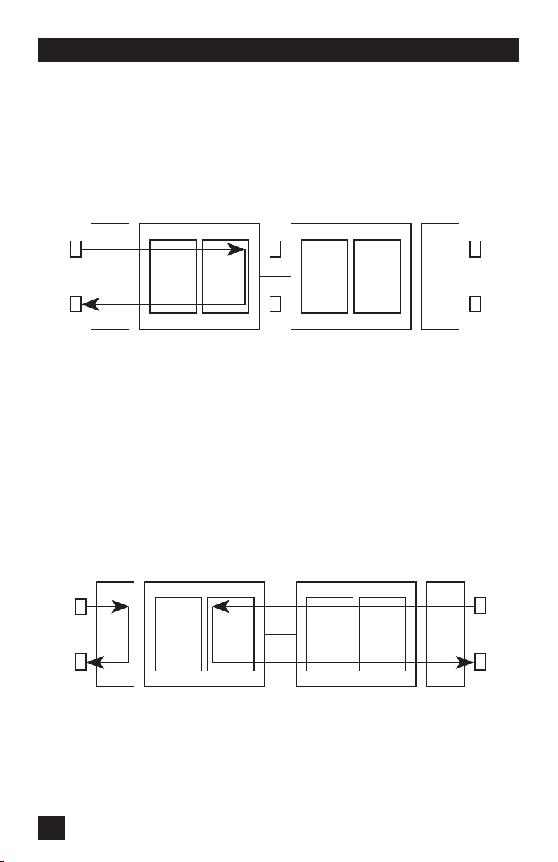
D.2.1 N
ETWORKTERMINATIONAPPLICATION
Network termination mode is used to connect a local site Line Driver using a
G.703/G.704 module to a remote-site Line Driver using a V.35, X.21, or RS-530
Ethernet Module (see Figure D-1). Transmitter clocking is derived from the
G.703/G.704 network and carried through the system to all system devices.
Page 46

45
APPENDIX D: G.703/G.704 Rear Card Module
Figure D-1. Clocking settings in a network termination application.
D.2.2 N
ETWORKEXTENSIONAPPLICATION
Network extension mode is used to extend nx64 to 2.048-Mbps G.703/G.704
service across a DSL link, providing an nx64 G.703/G.704 link at the remote site.
Transmitter clocking is derived from the G.703/G.704 network and is transmitted
over the baseband line driver link (see Figure D-2).
Figure D-2. Clock settings in a network extension application.
Clock/
Data
Clock/
Data
V.35
Router
Data
Clock/
Data
nx64 kbps
G.703/G.704
Network
Module and
Line Driver
Line Driver with
Serial Interface
Module
ME0004C ME0004C
Cable
Span
V.35
Module
External
Clocking
Receive Recover
Clocking
Clock/
Data
Clock/
Data
Clock/
Data
Clock/
Data
nx64 kbps
G.703/G.704
Network
nx64 kbps
G.703/G.704
Network
Module and
Line Driver
Module and
Line Driver
Module
ME0004C ME0004C
Cable
Span
Module
External
Clocking
External Clocking
set to force CP
Page 47

46
HIGH-SPEED 2-WIRE SHORT-RANGE DSL LINE DRIVER RACK CARD
D.3 Configuration
The G.703/G.704 Rear Card module can be configured via hardware switches and
jumpers. Sections D.3.1 and D.3.2 describe all switch and jumper configurations.
D.3.1 DIP-S
WITCHCONFIGURATION
The module has eight internal DIP switches (S1-1 through S1-8). The DIP switches
can be configured as either On or Off. Figure D-3 shows the location of the DIP
switches on top of the Rear Card printed circuit board.
Figure D-3. Top view of the Rear Card, showing the location of the DIP
switches.
Switch S1-1: Line Coding
Use switch S1-1 to control the network line-coding options. Set these options to the
same as the line coding that has been provided by your service provider.
Table D-1. Line coding.
S1-1 Line Framing and Coding
Off HDB3
On AMI
DIP switches
Front panel
Rear
Page 48

47
APPENDIX D: G.703/G.704 Rear Card Module
Line Coding Options
High Density Bipolar 3 (HDB3)
: In HDB3 coding, the transmitter deliberately
inserts a bipolar violation when excessive zeros in the data stream are detected.
The receiver recognizes these special violations and decodes them as zeros. This
method enables the network to meet minimum pulse-density requirements. Use
HDB3 unless AMI is required in your application.
Alternate Mark Inversion (AMI)
: AMI coding does not inherently account for ones
density. To meet this requirement, you should make sure that the data inherently
meets pulse density requirements.
Switch S1-2: CRC-4 Multiframe
CRC-4 multiframe uses time slot zero to carry CRC-4 information. When CRC-4 is
enabled (ON), the unit synchronizes to the CRC-4 multiframe protocol.
Table D-2. CRC-4 multiframe.
S1-2 Option
Off Disabled
On Enabled
NOTE
When the data rate is set to 2048 kbps, the module transmits user data
on all 32 timeslots, ignoring framing information. In this case, switch
S1-2 will be ignored.
Switch S1-3: Clear Channel Mode
When S1-3 is in the Off position, the module is running in G.703 clear channel
mode. When S1-3 is in the On position, the module is running in G.704 framed
mode. When the module is set to framed mode, channel 0 will be used to pass
G.704 framing information that results in a maximum bandwidth of 1984 kbps for
user data.
Table D-3. Clear channel mode.
S1-3 Option
Off Clear Channel Mode (G.703)
On Framed Mode (G.704)
Page 49

48
HIGH-SPEED 2-WIRE SHORT-RANGE DSL LINE DRIVER RACK CARD
Switches S1-4 through S1-8: Reserved
These switches are reserved for future use and should be set to OFF.
D.3.2 J
UMPERCONFIGURATION
The module has four jumpers (two position headers): JP4, JP5, JP6, and JP7. These
jumpers are used to select input and output impedance matching between the
module and external line. Figure D-4 shows the jumper locations.
Figure D-4. Top view of the rear card module, showing the location of the
jumpers.
The following is a description of the jumper settings with respect to the front-panel
connectors.
1. For a 75-ohm connection (coax), install JP4–JP7 (default).
2. For a 120-ohm connection (RJ-48C), remove JP4–JP7.
D.4 Installing the Rear Card and Front Function Card
See Section 4.2.
DIP switches
Front panel
Rear
Page 50

49
APPENDIX D: G.703/G.704 Rear Card Module
D.5 Making Interface Connections
The module may be connected to G.703/G.704 ports using a single 120-ohm RJ48C or a dual 75-ohm coax (BNC) connector. The module rear panels and the
location of these connectors are shown in Figure D-5.
Figure D-5. Module rear panels, showing the location of the connectors.
D.5.1 C
ONNECTTWISTEDPAIR
(120
OHM) TO
G.703/G.704 N
ETWORK
The module is equipped with a single RJ-48C jack for connections to a 120-ohm
twisted-pair G.703/G.704 network interface. If your G.703/G.704 network
terminates via RJ-48C, use Figure D-6 and Table D-4 to make the proper
connections. The connector pinout and signals are shown in Figure D-6. Use
Figure D-7 to connect the 120-ohm G.703/G.704 network channel.
Page 51

50
HIGH-SPEED 2-WIRE SHORT-RANGE DSL LINE DRIVER RACK CARD
Figure D-6. 120-ohm RJ-48C G.703/G.704 interface.
Table D-4. RJ-48C cable (8-wire).
Module Signal Pin # G.703/G.704
Network Signal
RX+ 1- - - - - - - - - - - - - - - - - - - - - - TX+
RX- 2- - - - - - - - - - - - - - - - - - - - - - TX-
TX+ 5- - - - - - - - - - - - - - - - - - - - - - RX+
TX- 4- - - - - - - - - - - - - - - - - - - - - - RX-
Shield 3- - - - - - - - - - - - - - - - - - - - - - Shield
Shield 6- - - - - - - - - - - - - - - - - - - - - - Shield
D.5.2 C
ONNECTDUALCOAXIALCABLE
(75
OHM)TO
G.703/G.704 N
ETWORK
The module is also equipped with dual female BNC connectors (TX and RX) for
connector to a 75-ohm dual coax G.703/G.704 network interface. If your
G.703/G.704 network terminates via dual coaxial cable, use Figure D-7 to make the
proper connections. The connector pinout and signals are also shown.
(Not connected) 8 - - - - - - - - - - - - -
(Not connected) 7 - - - - - - - - - - - - -
(Not connected) 6 - - - - - - - - - - - - -
(TX+) 5 - - - - - - - - - - - - -
(TX-) 4 - - - - - - - - - - - - -
(Not connected) 3 - - - - - - - - - - - - -
(RX-) 2 - - - - - - - - - - - - -
(RX+) 1 - - - - - - - - - - - - -
Page 52

51
APPENDIX D: G.703/G.704 Rear Card Module
Figure D-7. 75-ohm dual coaxial G.703 interface.
NOTE
The outer conductor of the coax cables are isolated from system earth
ground.
(Data FROM
G.703/G.704
network)
(Data TO
G.703/G.704
network)
Page 53

52
HIGH-SPEED 2-WIRE SHORT-RANGE DSL LINE DRIVER RACK CARD
Appendix E. 10BASE-T Ethernet
Rear Card Module
E.1 Description
The Ethernet Bridge Module installs in the Managed Micro Rack system to provide
seamless Ethernet LAN extension. The Module bridges two physically separate
Ethernet LANs at the MAC level. Operation of the Module is transparent to higher
network level protocols such as TCP/IP, DECnet™, NetBIOS
®
, and IPX™. The
Ethernet Bridge Module is 802.3 compliant and supports PPP (RFC 1661) with
Bridging Control Protocol (RFC 1638).
Once installed in the local Managed Micro Rack, the Ethernet Bridge Module
works in a plug-and-play manner to forward LAN broadcasts, multicasts, and
frames destined for the peered Ethernet LAN at the remote end (the base unit at
the remote end must be equipped with an Ethernet Module). Using the Ethernet
Bridge Module, peered Ethernet LANs can be linked over leased 2-wire/4-wire,
DDS, PCM, and campus fiber circuits.
The Ethernet Bridge Module plugs directly into the rear of a Rack Card Line
Driver (ME0001C or ME0004C). The Bridge Modules must be used in pairs.
Figure E-1 shows a typical installation.
Figure E-1. Typical application.
Corporate
Headquarters
Remote/Satellite
Office
Rackmounted Ethernet
WAN Bridge Module
2.3 Mbps
Leased Line
Ethernet Bridge
Module
LAN
LAN
Page 54

53
APPENDIX E: 10BASE-T Ethernet Rear Card Module
E.2 Configuration
The 10BASE-T Ethernet Rear Card Module plugs into the ME0001C and ME0004C
Line Drivers to provide Ethernet LAN extension. The Ethernet Card has no
switches or jumpers and does not need to be configured. However, factors such as
the type of medium, throughput across the link, and clocking mode must be
determined by the settings of the baseband Line Drivers (ME0001C and
ME0004C).
1. Bit rate: The DTE rate setting of your base unit corresponds with the
throughput of your Ethernet Bridge Module. Use higher speeds to allow
maximum throughput to your extended LAN. Use lower speeds to limit the
access of your extended LAN.
NOTE
The Ethernet Bridge Module only supports synchronous speeds.
2. Clocking mode: Set the clocking modes on the base units so that one unit is
configured for internal clocking mode and the other unit is set for receive
recover clocking mode.
Table E-1. Base unit clock modes.
Unit A Unit B
Internal clock setting Receive recover clock setting
NOTE
Unit A and B are chosen arbitrarily. It does not matter which unit is A
and which is B.
3. When using the Ethernet Bridge Module, disable the Enable Loop from the
DTE switch on the front function card (ME0003C or ME0004C).
4. All other base settings depend upon your application and on the application
medium (twisted-pair or coaxial cable).
E.3 Connecting the Interface Driver Board
Included in your 10BASE-T Ethernet Bridge Module package is an interface driver
board that allows you to configure your front function card for Ethernet operation.
Figure E-2 shows the interface driver board connected to a ME0003C or ME0004C
front function card.
Page 55

54
HIGH-SPEED 2-WIRE SHORT-RANGE DSL LINE DRIVER RACK CARD
Figure E-2. Interface driver board mounted on a ME0003C or ME0004C
front card.
Follow the instructions below to connect the interface driver board to the front
function card.
1. With the function card pulled out of the Managed Micro Rack, locate the
driver board to be replaced on the top of the base unit front card.
2. Lift the old interface board gently off the printed circuit board.
3. Position the interface driver board on top of the function card’s PC board
with the sockets oriented toward the male pins. Be sure that the label marked
FRONT
is pointed toward the front of the function card (toward the LEDs).
4. Push the interface driver board gently onto the socket and re-install the
function card into the rack.
E.4 Installing the Rear Interface Card and the Front Function Card
See Section 4.2.
Interface Driver Board
Front
Rear
10BASE-T
Ethernet Bridge
Module
Page 56

55
APPENDIX E: 10BASE-T Ethernet Rear Card Module
E.5 Connecting to the 10BASE-T Ethernet Port
The 10BASE-T Ethernet Rear Card module provides line side connections through
an RJ-45 connector. Figure E-3 shows the rear panel and the locations of the
connectors.
Figure E-3. Rear-panel RJ-45 connectors.
The RJ-45 Ethernet port on the rear card connects directly to a 10BASE-T network.
Figure E-4 shows the 10BASE-T RJ-45 port pin description. You may make
connections up to 330 feet (100 m) using Type 4 or 5 cable.
RJ-45
Line Side
10BASE-T
Connector
Page 57

56
HIGH-SPEED 2-WIRE SHORT-RANGE DSL LINE DRIVER RACK CARD
Figure E-4. Ethernet connector pinout.
E.5.1 C
ONNECTING THE
10BASE-T E
THERNETPORT TO AHUB
The 10BASE-T Ethernet rear card’s 10BASE-T interface is configured as a DTE
(Data Terminal Equipment), just like a 10BASE-T network interface card in a PC.
Therefore, it expects to connect to a 10BASE-T hub using a straight-through RJ-45
cable. Use Figure E-5 to construct a cable to connect the rear card to a 10BASE-T
hub.
Rear Card 10BASE-T Hub
RJ-45 Pin No. RJ-45 Pin No.
1 (TD+) - - - - - - - - - - - - - - - - - - - - 1 (RD+)
2 (TD-)- - - - - - - - - - - - - - - - - - - - - 2 (RD-)
3 (RD+) - - - - - - - - - - - - - - - - - - - - 3 (TD+)
6 (RD-) - - - - - - - - - - - - - - - - - - - - 6 (TD-)
Figure E-5. Straight-through cabling.
E.5.2 C
ONNECTING THE
10BASE-T E
THERNETPORT TO A
PC (DTE)
The rear card interface is configured as DTE (Data Terminal Equipment). If you
wish to connect the rear card to another DTE device such as a 10BASE-T network
interface card in a PC, you must construct a 10BASE-T crossover cable as shown in
Figure E-6.
- - - - - - - - - - - - - - - - - 1 TD+ (data output from ME0004C)
- - - - - - - - - - - - - - - - - 2 TD- (data output from ME0004C)
- - - - - - - - - - - - - - - - - 3 RD+ (data input to ME0004C)
- - - - - - - - - - - - - - - - - 4 Not connected
- - - - - - - - - - - - - - - - - 5 Not connected
- - - - - - - - - - - - - - - - - 6 RD - (data input to ME0004C)
- - - - - - - - - - - - - - - - - 7 Not connected
- - - - - - - - - - - - - - - - - 8 Not connected
Page 58
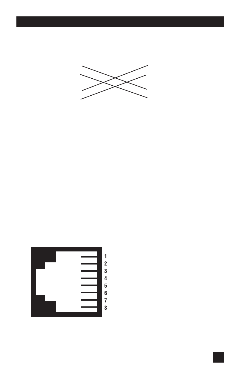
57
APPENDIX E: 10BASE-T Ethernet Rear Card Module
Rear Card 10BASE-T DTE
RJ-45 Pin No. RJ-45 Pin No.
1 (TD+) 1 (TD+)
2 (TD-) 2 (TD-)
3 (RD+) 3 (RD+)
6 (RD-) 6 (RD-)
Figure E-6. Crossover cabling.
E.5.3 C
ONNECTING THELINEINTERFACE
The 10BASE-T Ethernet rear card must be used with a front function card. There
are two essential requirements for connecting the line interface on the rear card.
1. These units work in pairs with one rear card connected to another rear card
over 2- or 4-wire twisted pair (2- or 4-wire operation is determined by the front
function card).
2. To function properly, the rear card needs one or two twisted pairs of metallic
wire (2- or 4-wire). The twisted pairs must be unconditioned, dry, metallic
wire, between 19 (0.9 mm) and 26 AWG (0.4 mm). Standard dial-up
telephone circuits that run through signal equalization equipment, or
standard, flat modular telephone type cable are not acceptable. See
Figure E-7.
Figure E-7. RJ-45 line interface.
- - - - - - - - - - - - - - - - - 1 Not connected
- - - - - - - - - - - - - - - - - 2 Not connected
- - - - - - - - - - - - - - - - - 3 (4-wire RX-)
- - - - - - - - - - - - - - - - - 4 (2-wire Tip) (4-wire TX+)
- - - - - - - - - - - - - - - - - 5 (2-wire Ring) (4-wire TX-)
- - - - - - - - - - - - - - - - - 6 (4-wire RX+)
- - - - - - - - - - - - - - - - - 7 Not connected
- - - - - - - - - - - - - - - - - 8 Not connected
Page 59

58
HIGH-SPEED 2-WIRE SHORT-RANGE DSL LINE DRIVER RACK CARD
NOTE
Two-wire line drivers use RJ-45 pins 4 and 5.
E.6 Operation
In order to operate, the rear card must be connected to a front function card and
installed in the rack unit. It also requires a 10BASE-T connection. After power is
applied, the rear card automatically starts performing the bridging function
without further user intervention. MAC addresses discovered are automatically
loaded into the MAC address table. They are automatically deleted from the MAC
address table if they experience an inactivity of 8 minutes.
E.6.1 P
OWER-UP
The rear card is hot-swappable. It receives power from the rack power bus.
Therefore, it is powered up as soon as it is plugged into the rack and the rack
power supply is turned on.
E.6.2 LED S
TATUSMONITORS
The 10BASE-T Ethernet rear card features two LEDs that monitor general
operating status and the 10BASE-T twisted-pair link integrity. Figure E-8 shows the
LEDs located directly beneath the RJ-45 jack. Following Figure E-8 is a description
of each LED’s function.
Figure E-8. 10BASE-T Ethernet Rear Card LED locations.
Status LED
(Yellow)
Link Integrity
LED (Green)
Page 60

59
APPENDIX E: 10BASE-T Ethernet Rear Card Module
• Status: Blinks yellow from one to eleven times to indicate system status. Each
pulse pattern is separated by a 2 second “off” period. Greater pulse patterns
have higher priority (buffer saturation has greater priority than an empty MAC
table). Valid system statuses are:
1 pulse = system status OK
2 pulses = no MAC entries in the MAC address table
3 pulses = Clear to Send (CTS) or Carrier Detect (CD) from base unit are
not asserted
4 pulses = Rear card buffer is saturated
5 pulses = WAN receive frame(s) too large
6 pulses = WN receive frame(s) not Octet aligned
7 pulses = WAN receive frame(s) aborted
8 pulses = Detected WAN receive frame(s) with bad CRC
9 pulses = Detected LAN receive frame(s) too large
10 pulses = Detected LAN receive frame(s) not Octet aligned
11 pulses = Detected LAN receive frame(s) with bad CRC
After a status code is displayed eight times and the associated condition is
removed, the status code will no longer appear.
• Link: Glows green to indicate good link integrity on the 10BASE-T twisted-pair
line.
Page 61

1000 Park Drive • Lawrence, PA 15055-1018 • 724-746-5500 • Fax 724-746-0746
© Copyright 2001. Black Box Corporation. All rights reserved.
 Loading...