

Black Box ME0001C-10BT, ME0001C-G703, ME0001C-V35, ME0001C-RS530, ME0001C-X21 User Manual
...Page 1

CUSTOMER
SUPPORT
INFORMATION
Order toll-free in the U.S.: Call 877-877-BBOX (outside U.S. call 724-746-5500)
FREE technical support 24 hours a day, 7 days a week: Call 724-746-5500 or fax 724-746-0746
Mailing address: Black Box Corporation, 1000 Park Drive, Lawrence, PA 15055-1018
Web site: www.blackbox.com • E-mail: info@blackbox.com
NOVEMBER 2001
ME0001C-10BT
ME0001C-G703
ME0001C-RS530
ME0001C-V24
ME0001C-V35
ME0001C-X21
2-Wire IDSL Line Driver Rack Cards
Page 2

1
FCC AND IC RFI STATEMENTS
FEDERAL COMMUNICATIONS COMMISSION
AND
INDUSTRY CANADA
RADIO FREQUENCY INTERFERENCE STATEMENTS
This equipment generates, uses, and can radiate radio frequency energy and if not
installed and used properly, that is, in strict accordance with the manufacturer’s
instructions, may cause interference to radio communication. It has been tested
and found to comply with the limits for a Class A computing device in accordance
with the specifications in Subpart B of Part 15 of FCC rules, which are designed to
provide reasonable protection against such interference when the equipment is
operated in a commercial environment. Operation of this equipment in a
residential area is likely to cause interference, in which case the user at his own
expense will be required to take whatever measures may be necessary to correct
the interference.
Changes or modifications not expressly approved by the party responsible
for compliance could void the user’s authority to operate the equipment.
This digital apparatus does not exceed the Class A limits for radio noise emission from
digital apparatus set out in the Radio Interference Regulation of Industry Canada.
Le présent appareil numérique n’émet pas de bruits radioélectriques dépassant les limites
applicables aux appareils numériques de la classe A prescrites dans le Règlement sur le
brouillage radioélectrique publié par Industrie Canada.
EUROPEAN UNION DECLARATION OF CONFORMITY
This equipment complies with the requirements of the European EMC Directive
89/336/EEC.
Page 3

2
2-WIRE IDSL LINE DRIVER RACK CARDS
NORMAS OFICIALES MEXICANAS (NOM)
ELECTRICAL SAFETY STATEMENT
INSTRUCCIONES DE SEGURIDAD
1. Todas las instrucciones de seguridad y operación deberán ser leídas antes de
que el aparato eléctrico sea operado.
2. Las instrucciones de seguridad y operación deberán ser guardadas para
referencia futura.
3. Todas las advertencias en el aparato eléctrico y en sus instrucciones de
operación deben ser respetadas.
4. Todas las instrucciones de operación y uso deben ser seguidas.
5. El aparato eléctrico no deberá ser usado cerca del agua—por ejemplo, cerca
de la tina de baño, lavabo, sótano mojado o cerca de una alberca, etc..
6. El aparato eléctrico debe ser usado únicamente con carritos o pedestales que
sean recomendados por el fabricante.
7. El aparato eléctrico debe ser montado a la pared o al techo sólo como sea
recomendado por el fabricante.
8. Servicio—El usuario no debe intentar dar servicio al equipo eléctrico más allá
a lo descrito en las instrucciones de operación. Todo otro servicio deberá ser
referido a personal de servicio calificado.
9. El aparato eléctrico debe ser situado de tal manera que su posición no
interfiera su uso. La colocación del aparato eléctrico sobre una cama, sofá,
alfombra o superficie similar puede bloquea la ventilación, no se debe colocar
en libreros o gabinetes que impidan el flujo de aire por los orificios de
ventilación.
10. El equipo eléctrico deber ser situado fuera del alcance de fuentes de calor
como radiadores, registros de calor, estufas u otros aparatos (incluyendo
amplificadores) que producen calor.
11. El aparato eléctrico deberá ser connectado a una fuente de poder sólo del
tipo descrito en el instructivo de operación, o como se indique en el aparato.
Page 4

3
NOM STATEMENT
12. Precaución debe ser tomada de tal manera que la tierra fisica y la polarización
del equipo no sea eliminada.
13. Los cables de la fuente de poder deben ser guiados de tal manera que no
sean pisados ni pellizcados por objetos colocados sobre o contra ellos,
poniendo particular atención a los contactos y receptáculos donde salen del
aparato.
14. El equipo eléctrico debe ser limpiado únicamente de acuerdo a las
recomendaciones del fabricante.
15. En caso de existir, una antena externa deberá ser localizada lejos de las lineas
de energia.
16. El cable de corriente deberá ser desconectado del cuando el equipo no sea
usado por un largo periodo de tiempo.
17. Cuidado debe ser tomado de tal manera que objectos liquidos no sean
derramados sobre la cubierta u orificios de ventilación.
18. Servicio por personal calificado deberá ser provisto cuando:
A: El cable de poder o el contacto ha sido dañado; u
B: Objectos han caído o líquido ha sido derramado dentro del aparato; o
C: El aparato ha sido expuesto a la lluvia; o
D: El aparato parece no operar normalmente o muestra un cambio en su
desempeño; o
E: El aparato ha sido tirado o su cubierta ha sido dañada.
Page 5

4
2-WIRE IDSL LINE DRIVER RACK CARDS
TRADEMARKS USED IN THIS MANUAL
DECnet™ is a trademark of Digital Equipment Corporation.
IPX™ is a trademark of Novell Incorporated.
NetBIOS
®
is a registered trademark of International Business Machines
Corporation.
VT100™ is a trademark of Compaq.
Any other trademarks mentioned in this manual are acknowledged to be the property of the
trademark owners.
Page 6

5
CONTENTS
Contents
Chapter Page
1. Specifications . . . . . . . . . . . . . . . . . . . . . . . . . . . . . . . . . . . . . . . . . . . . . . . . . . . . 7
2. Introduction. . . . . . . . . . . . . . . . . . . . . . . . . . . . . . . . . . . . . . . . . . . . . . . . . . . . . 8
2.1 Description. . . . . . . . . . . . . . . . . . . . . . . . . . . . . . . . . . . . . . . . . . . . . . . . . . . 8
2.2 Features . . . . . . . . . . . . . . . . . . . . . . . . . . . . . . . . . . . . . . . . . . . . . . . . . . . . . 8
2.3 SNMP Management. . . . . . . . . . . . . . . . . . . . . . . . . . . . . . . . . . . . . . . . . . . . 9
3. Configuration . . . . . . . . . . . . . . . . . . . . . . . . . . . . . . . . . . . . . . . . . . . . . . . . . . 10
3.1 Hardware Setup . . . . . . . . . . . . . . . . . . . . . . . . . . . . . . . . . . . . . . . . . . . . . . 10
3.1.1 Reversible Interface Driver Board . . . . . . . . . . . . . . . . . . . . . . . . . . . 11
3.1.2 Configuration Switch S1 . . . . . . . . . . . . . . . . . . . . . . . . . . . . . . . . . . . 12
3.1.3 Configuration Switch S2 . . . . . . . . . . . . . . . . . . . . . . . . . . . . . . . . . . . 15
3.1.4 Configuration Switch S5 . . . . . . . . . . . . . . . . . . . . . . . . . . . . . . . . . . . 16
3.2 Configure the Software Switches . . . . . . . . . . . . . . . . . . . . . . . . . . . . . . . . 17
3.3 Configure the Rear Interface Card . . . . . . . . . . . . . . . . . . . . . . . . . . . . . . 28
3.3.1 DB25/RJ-45 Rear Card (RS-530 and V.24) Strap Settings . . . . . . . . 28
3.3.2 M/34/RJ-45 Rear Card (V.35) Strap Settings. . . . . . . . . . . . . . . . . . 30
3.3.3 DB15 Rear Card (X.21) Strap Settings . . . . . . . . . . . . . . . . . . . . . . . 31
4. Installation . . . . . . . . . . . . . . . . . . . . . . . . . . . . . . . . . . . . . . . . . . . . . . . . . . . . . 35
4.1 The Rack Chassis . . . . . . . . . . . . . . . . . . . . . . . . . . . . . . . . . . . . . . . . . . . . . 35
4.2 Installing the Card into the Chassis . . . . . . . . . . . . . . . . . . . . . . . . . . . . . . 36
4.3 Wiring the Card . . . . . . . . . . . . . . . . . . . . . . . . . . . . . . . . . . . . . . . . . . . . . . 36
4.3.1 Connect to a DTE Device . . . . . . . . . . . . . . . . . . . . . . . . . . . . . . . . . . 36
4.3.2 Connect to a DCE Device . . . . . . . . . . . . . . . . . . . . . . . . . . . . . . . . . . 36
4.3.3 Connect to the Twisted-Pair Interface. . . . . . . . . . . . . . . . . . . . . . . . 37
4.3.4 Connect to the Control Port Interface . . . . . . . . . . . . . . . . . . . . . . . 38
5. Operation. . . . . . . . . . . . . . . . . . . . . . . . . . . . . . . . . . . . . . . . . . . . . . . . . . . . . . 39
5.1 LED Status Indicators . . . . . . . . . . . . . . . . . . . . . . . . . . . . . . . . . . . . . . . . . 39
5.2 Test Modes . . . . . . . . . . . . . . . . . . . . . . . . . . . . . . . . . . . . . . . . . . . . . . . . . . 40
5.2.1 Local Line Loopback (LLB) . . . . . . . . . . . . . . . . . . . . . . . . . . . . . . . 40
5.2.2 Remote Digital Loopback (RDL) . . . . . . . . . . . . . . . . . . . . . . . . . . . 41
5.2.3 V.52 (BER) Test-Pattern Generator. . . . . . . . . . . . . . . . . . . . . . . . . . 42
Appendix A. Terminal Interface Pin Assignments . . . . . . . . . . . . . . . . . . . . . . . 43
Appendix B. Control Port Pin Assignment (RJ-45 Connector
on RM262C Card) . . . . . . . . . . . . . . . . . . . . . . . . . . . . . . . . . . . . . . . . . . . . . . . 47
Appendix C. Line Interface Pin Assignment (RJ-45 Connector) . . . . . . . . . . . 48
Page 7

6
2-WIRE IDSL LINE DRIVER RACK CARDS
Chapter Page
Appendix D G.703 Rear Card Module . . . . . . . . . . . . . . . . . . . . . . . . . . . . . . . . 49
D.1 Description . . . . . . . . . . . . . . . . . . . . . . . . . . . . . . . . . . . . . . . . . . . . . . . . . 49
D.2 Typical Application. . . . . . . . . . . . . . . . . . . . . . . . . . . . . . . . . . . . . . . . . . . 49
D.3 DIP-Switch Configuration . . . . . . . . . . . . . . . . . . . . . . . . . . . . . . . . . . . . . 50
D.4 Installing the Rear Card and Front Function Card . . . . . . . . . . . . . . . . . 52
D.5 Making Interface Connections . . . . . . . . . . . . . . . . . . . . . . . . . . . . . . . . . 53
D.5.1 Connecting to a G.703 PCM Network Channel. . . . . . . . . . . . . . . . 54
D.5.2 Connecting the Line Interface . . . . . . . . . . . . . . . . . . . . . . . . . . . . . 55
D.5.3 Two-Wire Cable Connection via RJ-45 . . . . . . . . . . . . . . . . . . . . . . . 56
Appendix E. 10BASE-T Ethernet Bridge Module. . . . . . . . . . . . . . . . . . . . . . . . 57
E.1 Description. . . . . . . . . . . . . . . . . . . . . . . . . . . . . . . . . . . . . . . . . . . . . . . . . . 57
E.2 Configuration . . . . . . . . . . . . . . . . . . . . . . . . . . . . . . . . . . . . . . . . . . . . . . . 58
E.3 Connecting the Interface Driver Board. . . . . . . . . . . . . . . . . . . . . . . . . . . 59
E.4 Installing the Rear Interface Card and the Front Function Card . . . . . . 60
E.5 Connecting to the 10BASE-T Ethernet Port . . . . . . . . . . . . . . . . . . . . . . . 60
E.5.1 Connecting the 10BASE-T Ethernet Port to a Hub . . . . . . . . . . . . . 61
E.5.2 Connecting the 10BASE-T Ethernet Port to a PC (DTE) . . . . . . . . 62
E.5.3 Connecting the Line Interface . . . . . . . . . . . . . . . . . . . . . . . . . . . . . 62
E.6 Operation. . . . . . . . . . . . . . . . . . . . . . . . . . . . . . . . . . . . . . . . . . . . . . . . . . . 63
E.6.1 Power-Up . . . . . . . . . . . . . . . . . . . . . . . . . . . . . . . . . . . . . . . . . . . . . . . 63
E.6.2 Status Indicators . . . . . . . . . . . . . . . . . . . . . . . . . . . . . . . . . . . . . . . . . 64
Page 8

7
CHAPTER1: Specifications
1. Specifications
Transmission Format: Synchronous or asynchronous
Transmission Line: One- or two-pair unconditioned twisted wire
Clocking: Internal, External, or Receive Recover
Table 1-1. Maximum distance for all data rates.
Distance Cable
10.8 mi (17.4 km) 19 AWG (0.9 mm)
7.2 mi (11.6 km) 22 AWG (0.64 mm)
5 mi (8 km) 24 AWG (0.5 mm)
3.4 mi (5.5 km) 26 AWG (0.4 mm)
Data Rates: Synchronous: 19.2, 32, 56, 64, and 128 kbps; Asynchronous: 0 to
38.4 kbps
Diagnostics: Local Line Loopback, Remote Digital Loopback, V.52-compliant bit
error rate pattern generator (511/511E)
Line Interface: Transformer-coupled 1500-VAC isolation
Indicators: LEDs: TD, RD, CTS, CD, DTR, TM, ER, and NS
Connectors: RJ-45 on line side; RJ-45 for 10BASE-T, DB25 female for RS-530 and
V.24, M/34 female for V.35, DB15 female for X.21, dual BNC for G.703/G.704
Temperature Tolerance: 32 to 122°F (0 to 50°C)
Humidity: 5 to 95% noncondensing
Size: Front card: 3.1"H x 0.95"W x 4.8"D (7.9 x 2.4 x 12.2 cm); Rear card: 3.3"H x
0.95"W x 2.8"D (8.4 x 2.4 x 7.1 cm)
Page 9

8
2-WIRE IDSL LINE DRIVER RACK CARDS
2. Introduction
2.1 Description
The 2-Wire IDSL Line Driver Rack Card allows synchronous or asynchronous data
to be transmitted up to 11 miles (17.7 km) over one or two twisted pair (2- or
4-wire). Supporting synchronous speeds up to 128 kbps and asynchronous speeds
up to 38.4 kbps, the Card is perfect for LAN interconnection or high-speed
Internet links.
To compensate for poor line quality, the Card supports 2B1Q encoding, automatic
equalization, and auto gain control. The Card is fully SNMP manageable using the
Managed Micro Rack SNMP/HTTP Card (part number RM261C-SNMP). Software
configuration is performed via the VT100™ screens. Swappable interface driver
boards and interface cards allow you to easily change applications between
10BASE-T, G.703, RS-530, V.24, V.35, or X.21. The Card also features convenient
front-panel diagnostic switches and LEDs that allow for easy setup, configuration,
and testing.
The Card is designed to fit into the 16-Port Managed Micro Rack (part number
RM260), a 2U-high (3.5") rack chassis. This chassis uses a mid-plane architecture,
allowing front cards to be plugged into different rear cards.
2.2 Features
• Synchronous data rates of 19.2, 32, 56, 64, and 128 kbps in all clock modes.
• Asynchronous data rates: Up to 38.4 kbps.
• SNMP manageable using the Managed Micro Rack SNMP/HTTP Card (part
number RM261C-SNMP).
• Full-duplex operation over one or two twisted pair (2- or 4-wires).
• Point-to-point distances up to 11 miles (17.7 km).
• Remote digital loopback, local line loopback diagnostics.
• Internal, external, or receive recovered clocking options.
• LED indicators for TD, RD, CTS, CD, DTR, TM, ER, and NS.
• Fits in the Managed Micro Rack (part number RM260), a 2U (3.5") rack
chassis.
Page 10
9
CHAPTER 2: Introduction
2.3 SNMP Management
The QuikConnect IDSL Line Driver (ME0009A) is SNMP manageable when
connected to a rackmounted 2-Wire IDSL Line Driver Rack Card (ME0001C).
SNMP management is enabled through a Managed Micro Rack SNMP/HTTP
Card (RM261C-SNMP) located in the 16-Port Managed Micro Rack (RM260).
HTTP/HTMP M
ANAGEMENT
The SNMP/HTTP Card maintains HTML pages that can be viewed through a Web
browser. You can display remote statistics and configure QuikConnect parameters
simply by entering the SNMP/HTTP Card’s IP address into the browser.
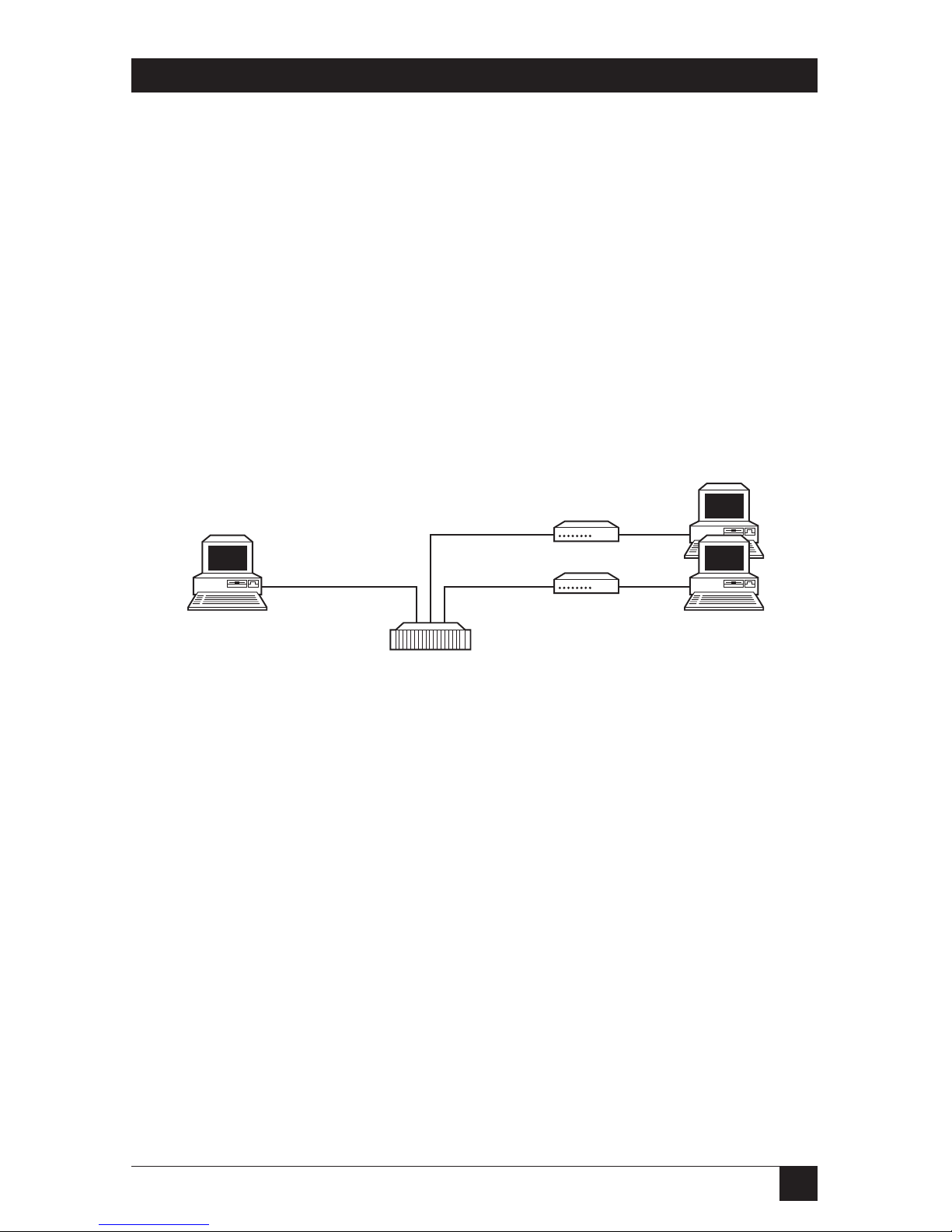
Figure 2-1. Typical application of the Line Driver Card.
Management
station
Rackmounted Line
Driver Cards
10BASE-T
connection to
RM262C
2B1Q connections
to remote Line
Drivers
Page 11
10
2-WIRE IDSL LINE DRIVER RACK CARDS
3. Configuration
This chapter describes the hardware and software configuration switches and
jumpers. Refer to the Managed Micro Rack SNMP/HTTP Card (RM261C-SNMP)
users’ manual for SNMP options.
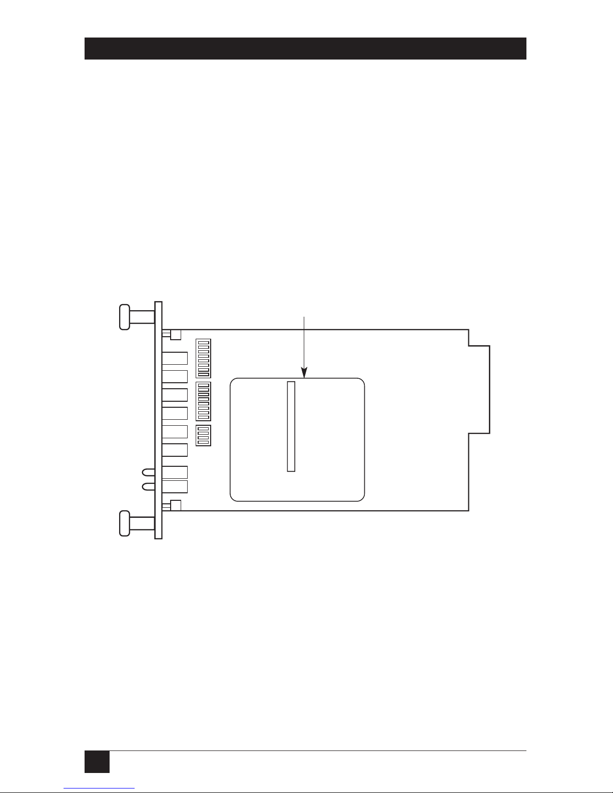
3.1 Hardware Setup
The 2-Wire IDSL Line Driver front card defaults to the use of hardware switches
for configuration. The front card has an interface driver board, two eight-position
DIP switches, and one 4-position DIP switch (see Figure 3-1).
Figure 3-1. Configuration switches and the interface driver board
on the front card.
Interface driver board
Page 12
11
CHAPTER 3: Configuration
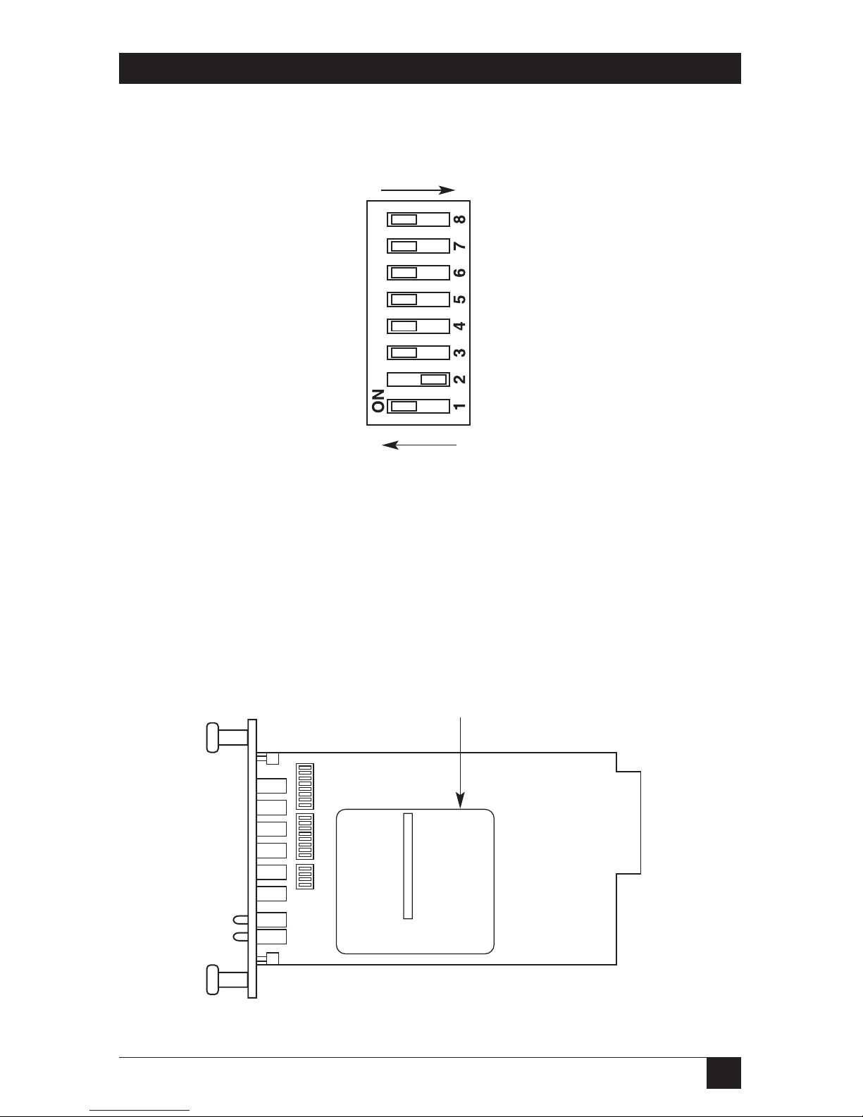
Figure 3-2 shows the orientation of the DIP switches with respect to the ON and
OFF positions.
Figure 3-2. Closeup of configuration switches.
NOTE
The ON position is oriented toward the front of the Card.
3.1.1 R
EVERSIBLEINTERFACEDRIVERBOARD
The 2-Wire IDSL Line Driver Rack Card features switchable interface driver boards
that allow a wide range of DTE interface connections. Figure 3-3 shows the
interface driver board on the top of the PC board.
Figure 3-3. Closeup of interface driver board.
OFF
ON
Interface driver
board
SW1
SW2
SW5
Page 13

12
2-WIRE IDSL LINE DRIVER RACK CARDS
Follow the instructions below to select the correct interface for your application:
1. With the 2-Wire IDSL Line Driver Rack Card pulled out of the rack chassis,
locate the driver board on the top of the front card.
2. Lift the interface board gently off of the PC board.
3. Locate the correct interface on the bottom of the driver board. For
example, the RS-232/V.35 interface board is marked “THIS SIDE UP FOR
RS-232” on one side and “THIS SIDE UP FOR V.35” on the other side.
4. Re-orient the interface board into the socket with the appropriate interface
pointed UP and with the arrow pointing toward the front panel of the PC
board.
5. Push the interface driver board gently onto the socket and re-install into the
rack system.
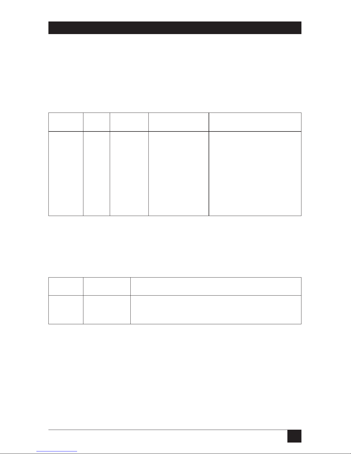
3.1.2 C
ONFIGURATIONSWITCH
S1
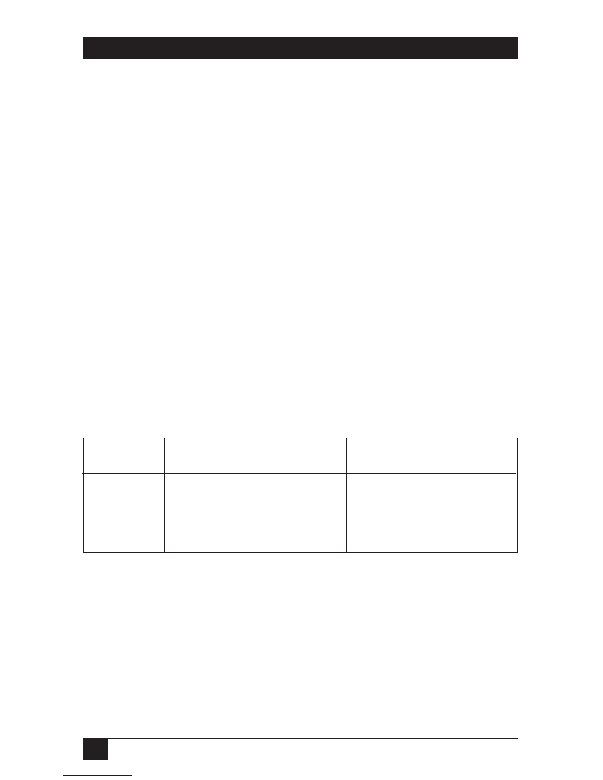
The configuration switches on S1 allow you to specify the data rate, async/sync
data format, transmit clock source, and response to RDL request. Default settings
of S1 are shown in Table 3-1.
Table 3-1. S1 summary.
Position Function Factory Default
S1-1 Data Rate On
S1-2 Data Rate Off
S1-3 DSR during Local Line Loop On DSR Enable
S1-4 Reserved Off
S1-5 Reserved Off
S1-6 Tx Clock Source On
S1-7 Tx Clock Source On
S1-8 Respond RDL Request On Enable
}
}
}
64K Sync
Reserved
Internal Clock
Page 14
13
CHAPTER 3: Configuration
Switches S1-1 and S1-2: Data Rate
Use Switches S1-1 and S1-2 with Switch S5-1 to determine the operable sync or
async bit rate for the 2-Wire IDSL Line Driver Rack Card. The settings shown in
Table 3-2 are the only applicable bit rate settings.
Table 3-2. Bit rate settings: S1-1, S1-2, and S5-1.
S1-1 S1-2 S5-1 Sync Data Rate Async Data rate
On On Off 32 kbps Reserved
Off On Off 56 kbps Reserved
On Off Off 64 kbps Reserved
Off Off Off 128 kbps 0 to 38.4 kbps
On On On Reserved Reserved
Off On On Reserved Reserved
On Off On Reserved Reserved
Off Off On 19.2 kbps Reserved
Switch S1-3: Data Set Ready During Local Line Loopback Test
Use Switch S1-3 to control the behavior of the DSR signal at the EIA interface
during the local line loopback test.
Table 3-3. DSR signal at the EIA interface during local line loopback test.
S1-3 Setting Description
On Enabled DSR is on during local line loop (default)
Off Disabled DSR is off during local line loop
Page 15

14
2-WIRE IDSL LINE DRIVER RACK CARDS
Switch S1-4: Management Setting
When setting the SNMP management, the DTE rate switches (S1-1, S1-2, and S2-1)
need to be in the ON position. Therefore, to set a Rack Card to SNMP
management mode, the following switches have to be at the ON position: S1-1,
S1-2, S5-1, and S1-4. Use Switch S1-4 to configure the Rack Card’s management
setting.
S1-4 Setting Description
On SNMP management using Netlink management
system
Off Control port management using VT100 control
port management
Switch S1-5: Reserved
Switches S1-6 and S1-7: Transmit Clock Source
Use Switches S1-6 and S1-7 to configure the Card for internal, external, or receive
recover clock mode.
Table 3-4. Transmit clock source.
S1-6 S1-7 Setting Description
On On Internal Transmit clock derived internally
Off On External Transmit clock derived from the
terminal interface
On Off Receive Recover Transmit clock derived from the
received line signal
Off Off Hardware Reset Reset to use hardware switches for
configuration.
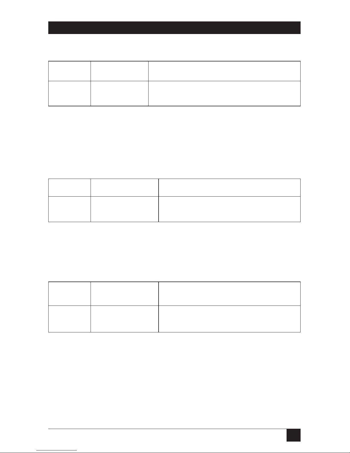
Switch S1-8: Response to Remote Loop Request
Use Switch S1-8 to allow the Card to enter the Remote Digital Loopback diagnostic
test when requested to do so by the far-end modem. For example, when Switch
S1-8 is set to “ON,” it will enter RDL mode (see Section 5.2.2) when requested to
do so by the remote modem.
Page 16

15
CHAPTER 3: Configuration
Table 3-5. Remote Digital Loopback Test.
S1-8 Setting
On Response to RDL request enabled
Off Response to RDL request disabled
3.1.3 C
ONFIGURATIONSWITCH
S2
The 2-Wire IDSL Line Driver Rack Cards may be configured by a menu-driven
software system when used with the Managed Micro Rack Control Module,
VT100™ (part number RM262C) or Managed Micro Rack SNMP/HTTP Card,
SNMP (part number RM261C-SNMP). In order to configure the 2-Wire IDSL
Line Driver Rack Card by software commands, you must set its control port
address.
The control port address is defined by a two-digit decimal number. Switches S2-1
through S2-4 define the least significant digit or the “ones” digit, and Switches S2-5
through S2-7 define the “tens” digit. Valid addresses are 0 through 79. Use
Table 3-6 and the instructions that follow the table to set the control port to the
desired address.
Table 3-6. S2 summary.
Address Switch S2 Settings
Digit 12345678
Default 0 ON ON ON ON ON ON ON ON
1 OFF ON ON ON OFF ON ON ON
2 ON OFF ON ON ON OFF ON ON
3 OFF OFF ON ON OFF OFF ON ON
4 ON ON OFF ON ON ON OFF ON
5 OFF ON OFF ON OFF ON OFF ON
6 ON OFF OFF ON ON OFF OFF ON
7 OFF OFF OFF ON OFF OFF OFF ON
8 ON ON ON ON N/A/ N/A N/A N/A
9 OFF ON ON OFF N/A N/A N/A ON
Page 17
16
2-WIRE IDSL LINE DRIVER RACK CARDS
Switches S2-1 through S2-4: Control Port Address— LSD
Use Switches S2-1 through S2-4 to set the least-significant digit of the ME0001C
control port address. For example, using Table 3-6, if the desired address is “63”,
the “3” is the least-significant digit in the address. Set Switches S2-1, S2-2, S2-3, and
S2-4 to OFF, OFF, ON, ON.
Switches S2-5 through S2-7: Control Port Address—MSD
Use Switches S2-5 through S2-7 to set the most-significant digit of the ME0001C’s
control port address. For example, using Table 3-6, if the desired address is “62,”
the “6” is the most-significant digit in the address. Set Switches S2-5, S2-6, and S2-7
to ON, OFF, OFF.
Switch S2-8: Reserved for Factory Use
Switch S2-8 is reserved for factory use and must remain in the ON position.
3.1.4 C
ONFIGURATIONSWITCH
S5
The configuration switches on S5 allow you to specify the data rate, 2-wire/4-wire
selection, and enable or disable loopback diagnostics. Default settings of S5 are
shown in Table 3-7.
Table 3-7. S5 summary.
Position Function Factory Default
S5-1 Data Rate Off
S5-2 2-Wire/4-Wire Off 2-wire
S5-3 Enable LAL or RDL from DTE On Enable
S5-4 Enable front-panel switches Off Disable
Switch S5-1: Data Rate
Use Switch S5-1 with Switches S1-1 and S1-2 to enable additional data rates.
Table 3-2 shows all possible bit rate settings for Switches S1-1, S1-2, and S5-1.
Switch S5-2: 2-Wire/4-Wire
Use Switch S5-2 to configure 2-wire or 4-wire operation.
Page 18
17
CHAPTER 3: Configuration
Table 3-8. 2-wire or 4-wire operation.
S5-2 Setting Description
Off 2-wire 2-wire operation
On 4-wire 4-wire operation
Switch S5-3: Enable LAL and RDL from DTE
Use Switch S5-3 to enable or disable the Local Analog Loopback and Remote
Digital Loopback control from the DTE.
Table 3-9. Enable or disable loopback.
S5-3 Setting Description
On Enabled LAL and RDL enabled
Off Disabled LAL and RDL disabled
Switch S5-4: Enable Front-Panel Switches
Use Switch S5-4 to enable or disable the front-panel switches.
Table 3-10. Enable front panel switches.
S5-4 Setting Description
On Enabled Front-panel switches enabled
Off Disabled Front-panel switches disabled
3.2 Configure the Software Switches
The 2-Wire IDSL Line Driver Rack Card features a menu-driven command system
that allows you to configure the local card. The software control port signals of the
ME0001C are carried to each card in the rack along the internal power bus board.
Access to all rack card control ports is provided by a single Managed Micro Rack
Control Module (see the RM262C users’ manual). After setting the control port
address (see Section 3.1.3), use the following instructions to configure the unit.
Page 19

18
2-WIRE IDSL LINE DRIVER RACK CARDS
1. Connect the serial RS-232 port of a VT100 or similar DTE with terminal
emulation to the EIA-561 control port on the Managed Micro Rack Control
Module (RM262C). To construct an RS-232 to EIA-561 patch cable, refer to
the control port pinout diagram in Appendix B.
2. Power up the terminal and set its RS-232 port as follows:
9600 baud
8 data bits, 1 stop bit, no parity
Local echo
CR-CR/LF on inbound data
ANSI, VT100 emulation
3. Press [CTRL+B] on the terminal followed by the two-digit control port
address.
4. To make a selection from any menu, enter the option number. To exit any
menu without making a selection, press the [ESC] key.
5. After the 2-Wire IDSL Line Driver Rack Card is powered on, the control port
will send out this message:
Model: ME0001C software version xx
Black Box Corporation Copyright © 2000
6. Press [ESC] on the terminal.
7. The 2-Wire IDSL Line Driver Rack Card will then display the Main Menu
screen. You may configure the Local Card from this screen.
IMPORTANT!
To make a selection from any menu, enter the option number. To exit
any menu without making a selection, or to return to the previous menu,
press the [ESC] key.
Page 20

19
CHAPTER 3: Configuration
C
ONFIGURE THELOCAL
2-W
IRE
IDSL L
INEDRIVERCARD
To configure the local Card, make a selection from the following Main Menu.
Figure 3-4. Main Menu.
Main Menu Option 1: Display Active Configuration
Select Option 1 to display the most-recent configuration of the local 2-Wire IDSL
Line (see Figure 3-5). The Card uses the active configuration for its operation. If
you make changes to the configuration, you must select Main Menu Option 8. This
will update the unit to the new active configuration.
Figure 3-5. Display active configuration.
QUIKCONNECT IDSL LINE DRIVER
LOCAL CONFIGURATION
MAIN MENU
1. DISPLAY ACTIVE CONFIGURATION
2. DISPLAY HARDWARE CONFIGURATION
3. DISPLAY SOFTWARE CONFIGURATION
4. SETUP SOFTWARE CONFIGURATION
5. SELECT HARDWARE/SOFTWARE CONTROL
6. DISPLAY MODEM STATUS
7. TEST MODES
8. RESTART UNIT
ENTER YOUR SELECTION (1-8)>
Page 21
20
2-WIRE IDSL LINE DRIVER RACK CARDS
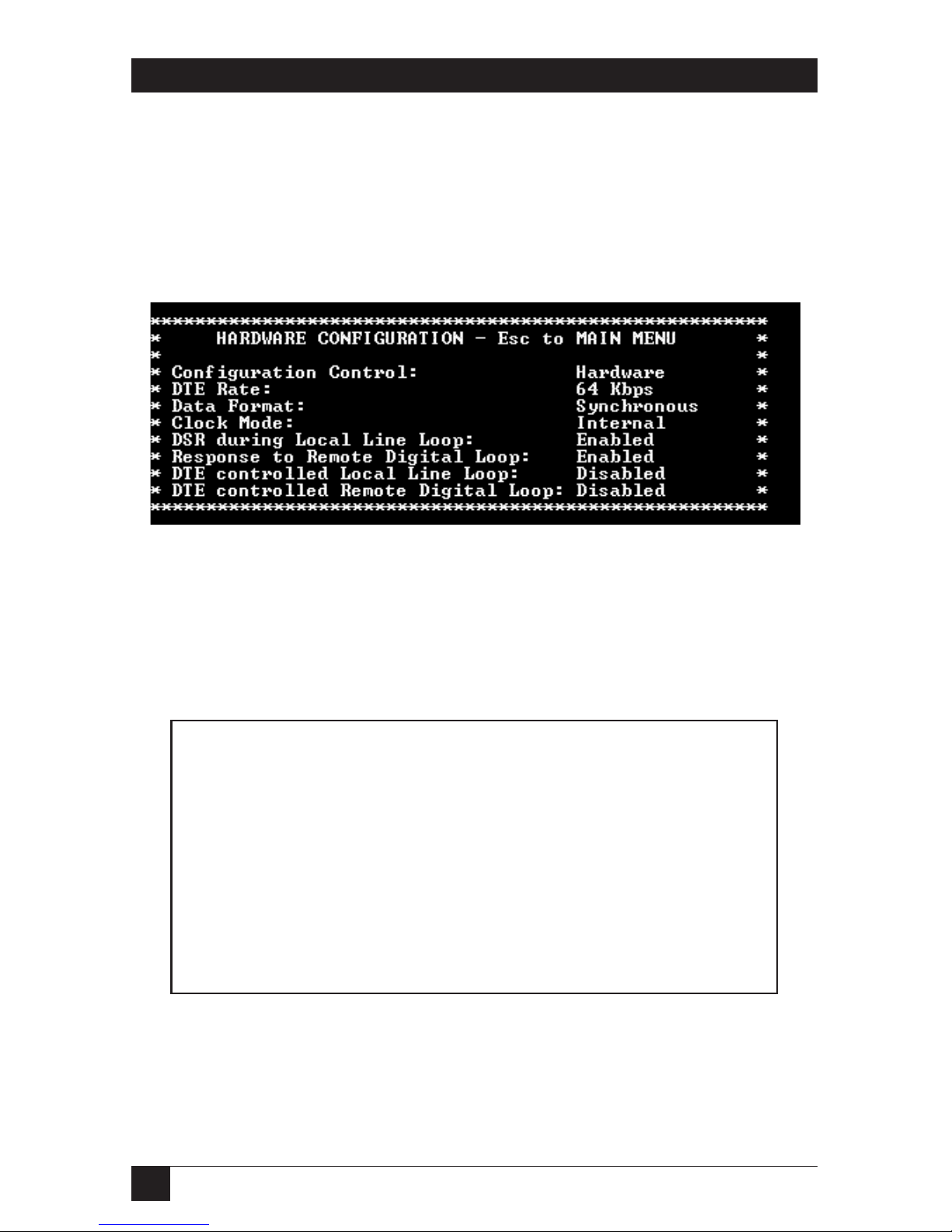
Main Menu Option 2: Display Hardware Configuration
Select Option 2 to display the configuration of the hardware DIP switches. To use
the Hardware Configuration for the Active Configuration, select Main Menu
Option 5. Then select “Use Hardware DIP-Switches.” Finally, select Main Menu
Option 8 to save.
Figure 3-6. Display hardware configuration.
Main Menu Option 3: Display Software Configuration
Select Option 3 to display the configuration of the software switches. To use the
software configuration for the active configuration, select Main Menu, Option 5.
Then select “Use Software Switches.” Finally, select Main Menu Option 8 to save.
Figure 3-7. Display software configuration.
SOFTWARE CONFIGURATION—Esc to Main Menu
Configuration Control: Hardware
DTE Rate: 64 kbps
Data Format: Synchronous
Clock Mode: Internal
DSR during Local Line Loop: Enabled
Response to Remote Digital Loop: Enabled
DTE controlled Local Line Loop: Disabled
DTE controlled Remote Digital Loop: Disabled
Page 22

21
CHAPTER 3: Configuration
Main Menu Option 4: Setup Software Configuration
Select Option 4 to edit the software configuration of the 2-Wire IDSL Line Driver
Rack Card. To save changes after editing the software configuration, select Main
Menu Option 5, then select “Use Software Switches” and then select Main Menu
Option 8 to save.
Figure 3-8. Setup software configuration.
1. DTE Rate
Select Option 1 in the Software Configuration menu to select the synchronous
DTE Rate of the 2-Wire IDSL Line Driver Rack Card.
Figure 3-9. DTE rate.
DTE RATE—ESC TO SOFTWARE CONFIG MENU
1. 32 KBPS 3. 64 KBPS (DEFAULT)
2. 56 KBPS 4. 128 KBPS
5. 19.2 KBPS
ENTER YOUR SELECTION (1-5)>
SOFTWARE CONFIGURATION MENU—Esc to Main Menu
1. DTE Rate
2. Data Format (Async/Sync)
3. Clock Mode
4. DSR during Local Line Loop
5. Response to Remote Digital Loop
6. DTE controlled Local Line Loop
7. DTE controlled Remote Digital Loop
8. 4-Wire/2-Wire selection
Page 23

22
2-WIRE IDSL LINE DRIVER RACK CARDS
2. Data Format
Select Option 2 in the Software Configuration menu to select the sync data format.
Figure 3-10. Data format.
3. Clock Mode
Select Option 3 in the Software Configuration menu to select the sync clock mode.
Figure 3-11. Clock mode.
Set this option as follows:
Master Clock—Internal: Select Item 1 to use the 2-Wire IDSL Line Driver Rack
Card’s internal reference clock as the timing source.
Master Clock—External: Select Item 2 to use the DTE-supplied transmit clock.
Slaved to Receive Clock: Select Item 3 to have the 2-Wire IDSL Line Driver Rack
Card derive a transmit clock from the incoming data stream.
IMPORTANT!
One Card must be a Master Clock (either internal or external) and the
other must be slaved to the Receive Clock.
DATA FORMAT—ESC TO SOFTWARE CONFIG MENU
1. SYNCHRONOUS/ASYNCHRONOUS
Page 24

23
CHAPTER 3: Configuration
4. DSR During Local Line Loop
Select Option 4 in the Software Configuration menu to configure the behavior of
the local Data Set Ready (DSR) signal during the Local Line Loop test mode.
Figure 3-12. DSR during local line loop.
5. Response to Remote Digital Loop
Select Option 5 in the Software Configuration menu to instruct the 2-Wire IDSL
Line Driver Rack Card to either respond or ignore the Remote Digital Loop
request from the remote Card.
Figure 3-13. Response to remote digital loop.
Page 25

24
2-WIRE IDSL LINE DRIVER RACK CARDS
6. DTE Controlled Local Line Loop
Select Option 6 in the Software Configuration menu to instruct the 2-Wire IDSL
Line Driver Rack Card to either respond or ignore Local Line Loop requests from
the DTE. To instruct the Card to respond to Local Line Loop requests from the
DTE, select Enable (Option 1). To instruct the Card to ignore Local Line Loop
requests from the DTE interface, select Disable (Option 2).
Figure 3-14. DTE controlled local line loop.
7. DTE Controlled Remote Digital Loop
Select Option 7 in the Software Configuration menu to enable DTE control of the
Remote Digital Loop menu. The Remote Digital Loop on the Card can be
controlled from the DTE interface by selecting Enable (Option 1). To instruct the
Card to ignore this request from the DTE interface, select Disable (Option 2).
Figure 3-15. DTE controlled remote digital loop.
Page 26

25
CHAPTER 3: Configuration
8. 2-Wire/4-Wire Selection
Select Option 8 in the Software Configuration menu to configure 2-Wire or 4-Wire
operation.
Figure 3-16. 2-Wire/4-Wire selection.
Main Menu Option 5: Select Hardware/Software Control
Option 5 from the Main Menu selects whether the 2-Wire IDSL Line Driver Rack
Card will use the hardware switch settings or the software switch settings for its
active configuration. If Options 1 or 2 are selected, the Card will use the current
hardware or software switch settings as the active configuration. After changing this
setting, select Main Menu Option 8 to implement the changes.
Figure 3-17. Hardware/software configuration control.
2-Wire/4-Wire Selection
1. 4-Wire Mode
2. 2-Wire Mode
Page 27

26
2-WIRE IDSL LINE DRIVER RACK CARDS
Main Menu Option 6: Display Modem Status
Select Option 6 from Main Menu to display the Modem Status. Press Return on the
keyboard to update and redisplay the screen.
Valid 2-Wire IDSL Line Driver Rack Card Handshake status conditions are listed
following Figure 3-18.
Figure 3-18. Modem status.
1. Handshaking: This status occurs when the 2-Wire IDSL Line Driver Rack Card
is in the process of establishing a link with another Card.
2. Data Mode: This status occurs when the Card successfully establishes a link
with another Card, allowing the data to flow.
Press the space bar to refresh the Modem Status page.
Page 28

27
CHAPTER 3: Configuration
Main Menu Option 7: Test Modes
Select Option 7 from the Main Menu to select the test mode status of the
ME0001C. The 2-Wire IDSL Line Driver test mode settings help to verify the
integrity of the data link and isolate communication difficulties.
Figure 3-19. Test mode menu.
To run or terminate a particular test, key in the option to get to that screen menu.
Test mode options 2, 3, 7, 8, and 9 require the Card to be in data mode with the
remote Card. The Card’s test modes are described below:
• OFF: Terminates all tests.
• 511: Initiates the built-in test-pattern generator and detector.
• 511 with Errors: Initiates the built-in test-pattern generator and detector. The
test-pattern generator also injects intentional errors approximately once per
second.
• Local Line Loop: Initiates a local line loop. Any data sent to the modem is
locally returned to its DTE interface.
• Local Line Loop and 511: Initiates the Local Line Loop test and starts the
internal 511 generator and detector.
• Local Line Loop and 511 w/errors: Initiates the Local Line Loop test and
starts the internal 511 generator and detector. In this test, the 511 pattern
generator injects intentional errors into the data stream.
• Remote Digital Loop: Initiates the Remote Digital Loopback test. Any data sent
to the remote Card is returned to the originating device.
Page 29

28
2-WIRE IDSL LINE DRIVER RACK CARDS
• Remote Digital Loop and 511: Initiates the Remote Digital Loopback test and
starts the internal 511 generator and detectors.
• Remote Digital Loop and 511 with errors: Initiates the Remote Digital
Loopback test and starts the 511 test patterns. In this test, the 511 pattern
generator will inject initial errors into the data stream.
The Modem Status screen is displayed upon initiating a test. Press ESC to return to
the Test Mode menu. Press the space bar to refresh the modem status page.
3.3 Configure the Rear Interface Card
The 2-Wire IDSL Line Driver Rack Card has several interface card options:
10BASE-T, G.703, RS-530, V.24, V.35, and X.21. Each of these options supports one
DTE interface connection and one 2-wire/4-wire twisted-pair line connection.
Before installation, you will need to examine the rear card to be sure it is properly
configured for your application. Each rear card is configured by setting straps
located on the PC board. To configure the rear cards, you must set the
configuration straps. Figure 3-20 shows the orientation of these straps. Each strap
can either be on pegs 1 and 2, or on pegs 2 and 3. Sections 3.3.1 through 3.3.3
describe the strap locations and possible settings for each rear card.
Figure 3-20. Orientation of interface card straps.
3.3.1 DB25/RJ-45 R
EARCARD
(RS-530
AND
V.24) S
TRAPSETTINGS
Figure 3-21 shows strap locations for the DB25/RJ-45S (RS-530 and V.24) rear
cards. These straps determine various grounding characteristics for the terminal
interface and twisted-pair lines. JB3 and JB4 are user configurable. JB2 must be set
on pegs 1 and 2.
123 123 123
Page 30

29
CHAPTER 3: Configuration
Figure 3-21. DB25/RJ-45 strap locations.
Table 3-11 provides an overview of interface strap functions for the rear interface
cards. Following the table overview are detailed descriptions of each strap’s
function.
Table 3-11. Interface card strap summary.
Strap Function Position 1 & 2 Position 2 & 3
JB3 DTE Shield (Pin 1 & FRGND) Connected* Open
JB4 SGND & FRGND Connected* Open
*Default setting
DTE Shield (DB25 Pin 1) and FRGND (JB3)
In the connected position, this strap links DB25 pin 1 and frame ground. In the
open position, pin 1 is disconnected from frame ground.
JB3
JB4
Page 31

30
2-WIRE IDSL LINE DRIVER RACK CARDS
JB3
Position 1 & 2 = DTE Shield (Pin 1) and FRGND connected
Position 2 & 3 = DTE Shield (Pin 1) and FRGND not connected
SGND and FRGND (JB4)
In the connected position, this strap links DB25 pin 7 (signal ground) and frame
ground. In the open position, pin 1 is disconnected from frame ground.
JB4
Position 1 & 2 = SGND (Pin 7) and FRGND connected
Position 2 & 3 = SGND (Pin 7) and FRGND not connected
3.3.2 M/34/RJ-45 R
EARCARD
(V.35) S
TRAPSETTINGS
Figure 3-22 shows the strap location for the M/34/RJ-45 (V.35) rear card. This
strap determines whether signal ground and frame ground will be connected.
Figure 3-22. M/34/RJ-45 strap locations.
JB4
Page 32

31
CHAPTER 3: Configuration
SGND and FRGND (JB4)
In the connected position, this strap links signal ground and frame ground. In the
open position, signal ground is disconnected from frame ground.
JB4
Position 1 & 2 = SGND and FRGND Connected*
Position 2 & 3 = SGND and FRGND Not Connected
*Default setting
3.3.3 DB15 R
EARCARD
(X.21) S
TRAPSETTINGS
Figure 3-23 shows strap locations for the DB15 (X.21) rear cards. These straps
determine various grounding characteristics for the terminal interface and
twisted-pair lines. JB3 and JB4 are user configurable.
Figure 3-23. Strap locations.
Table 3-11 provides an overview of interface strap functions for the rear interface
cards. Following the table overview are detailed descriptions of each strap’s
function.
JB3
JB4
Page 33

32
2-WIRE IDSL LINE DRIVER RACK CARDS
Table 3-12. Interface card strap summary.
Strap Function Position 1 & 2 Position 2 & 3
JB3 DTE Shield (Pin 1) and FRGND Connected* Open
JB4 SGND and FRGND (Pin 8) Connected* Open
*Default setting
DTE Shield (DB15 Pin 1) and FRGND (JB3)
In the connected position, this strap links DB15 pin 1 and frame ground. In the
open position, pin 1 is disconnected from frame ground.
JB3
Position 1 & 2 = DTE Shield (Pin 1) and FRGND connected
Position 2 & 3 = DTE Shield (Pin 1) and FRGND not connected
SGND & FRGND (JB4)
In the connected position, this strap links DB15 pin 8 (Signal Ground) and frame
ground through a 100-ohm resistor. In the open position, pin 8 is connected
directly to frame ground.
JB4
Position 1 & 2 = SGND (Pin 8) and FRGND connected through a 100-ohm resistor
Position 2 & 3 = SGND (Pin 8) and FRGND directly connected
Page 34

33
CHAPTER 3: Configuration
Installing the X.21 Daughterboard onto the X.21 Line Driver Card
Figure 3-24 shows the X.21 daughterboard, DCE/DTE selector, and jumper (JP1)
location with respect to the rack card. Following Figure 3-24 are guidelines for the
installation of the X.21 daughterboard, setting for DCE/DTE, and a brief
description of Jumper JP1.
Figure 3-24. View of the X.21 daughterboard, DCE/DTE selector, and JP1.
Follow the steps below for proper installation of the X.21 daughterboard.
WARNING
The X.21 daughterboard connector is not keyed and can be installed
incorrectly.
1. On the top side of the X.21 daughterboard, locate the designator shown
below:
Front X.21
2. Install the X.21 daughterboard onto the front card with the “Front X.21”
arrow pointing to the front panel of the rack card (see Figure 3-24).
X.21 Daughterboard
DCE/DTE
selector
Front
panel
Rear
Rack Card
Front X.21
JP1
Page 35

34
2-WIRE IDSL LINE DRIVER RACK CARDS
DCE/DTE Selector for the X.21 Daughterboard
The X.21 daughterboard can be set up as a DCE (default) or DTE device. The
DCE/DTE selector must be installed in the X.21 daughterboard for any
configuration. The following information describes the setting for DCE/DTE.
• DCE setting (default): To set a rack card as a DCE device, install the
DCE/DTE selector with the DCE arrows pointing toward the front panel.
• DTE setting: To set a rack card as a DTE device, install the DCE/DTE selector
with the DTE arrows pointing toward the front panel.
Jumper (JP1) Setting
The X.21 daughterboard operates at speeds up to 2.3 Mbps. When using the
daughterboard at data rates of 2 Mbps or higher, clocking issues may introduce bit
errors. Bit errors can also occur when long cables are used to interconnect the
modem to an X.21 terminal device (router, multiplexor, etc.). To solve bit error
problems due to speed and/or long cables, the X.21 daughterboard is equipped
with a jumper selector (JP1) that changes the sampling edge of the transmit clock.
Refer to Figure 3-24 for jumper JP1 location.
The following is a brief description of JP1 setting and function.
• Normal setting: The jumper shorts the two outer pins of JP1. Figure 3-24 shows
the default position. This position is selected when operating at low data rate
(less than 2 Mbps) and using a short X.21 terminal cable.
• Invert setting: The jumper shorts the two inner pins of JP1. This setting is
selected when operating at data rates of 2 Mbps or higher or when using long
X.21 terminal cables.
NOTE
The G.703 Rear Card module is covered in Appendix D. The 10BASE-T
Ethernet Rear Card module is covered in Appendix E.
Page 36

35
CHAPTER 4: Installation
4. Installation
This chapter describes the functions of the 16-Port Managed Micro Rack (RM260)
chassis, tells how to install front and rear 2-Wire IDSL Line Driver Rack Cards into
the chassis, and how to connect to the twisted-pair interface and the serial
interface.
4.1 The Rack Chassis
The 16-Port Managed Micro Rack Chassis (Figure 4-1) has 16 card slots plus its own
power supply. Measuring only 3.5" high, the Rack Chassis is designed to occupy
only 2U in a 19" rack. Sturdy front handles allow the Rack Chassis to be extracted
and transported conveniently.
Figure 4-1. The Rack chassis with power supply.
THER
ACKPOWERSUPPLY
The power supply included in the Managed Micro Rack uses the same mid-plane
architecture as the modem cards. The front card of the power supply slides in from
the front, and the rear card slides in from the rear. They plug into one another in
the middle of the rack. The front card is then secured by thumbscrews, the rear
card by conventional metal screws.
WARNING
There are no user-serviceable parts in the power-supply section of the
Managed Micro Rack Chassis. Only qualified service personnel should
change the voltage settings and replace the fuses. Contact Black Box
Technical Support at 724-746-5500 for more information.
Page 37

36
2-WIRE IDSL LINE DRIVER RACK CARDS
4.2 Installing the Card into the Chassis
The 2-Wire IDSL Line Driver Rack Card is comprised of a front card and a rear
card. The two cards meet inside the rack chassis and plug into each other via
mating 50-pin card-edge connectors. Use the following steps as a guideline for
installing each Card into the rack chassis:
1. Slide the rear card into the back of the chassis along the metal rails provided.
2. Secure the rear card using the metal screws provided.
3. Slide the front card into the front of the chassis. It should meet the rear card
when it’s almost all the way into the chassis.
4. Push the front card gently into the card-edge receptacle of the rear card. It
should “click” into place.
5. Secure the front card using the thumb screws.
4.3 Wiring the Card
Each of the rear interface cards compatible with the 2-Wire IDSL Line Driver Rack
Cards has one terminal interface port and one 2-wire/4-wire (twisted-pair) port.
For specific interface pinouts, refer to the diagrams in the Appendix C of this
manual.
4.3.1 C
ONNECT TO A
DTE D
EVICE
Regardless of the interface module you choose, the Card’s serial port is always
wired as a DCE. It plugs into a DTE such as a terminal, PC, or host. When making
the connection to your DTE device, use a straight-through cable of the shortest
possible length that is appropriate to the interface you are using. When purchasing
or constructing an interface cable, please refer to the pin diagrams in Appendix C
as a guide.
4.3.2 C
ONNECT TO A
DCE D
EVICE
Since the 2-Wire IDSL Line Driver Rack Card’s serial port is always wired as a DCE,
you must use a null-modem cable when connecting to another DCE device such as
a CSU/DSU, modem, or multiplexor. This cable should be of the shortest possible
length that is appropriate to the interface you are using. When purchasing or
constructing a null-modem interface cable, use the pin diagrams in Appendix C as
a guide.
Page 38

37
CHAPTER 4: Installation
4.3.3 C
ONNECT THETWISTED-PAIRINTERFACE
The 2-Wire IDSL Line Driver Rack Card supports communication between two
DTE devices at distances to 5 miles (8 km) over 24-AWG (0.5-mm) twisted-pair
wire. There are two essential requirements for installing the Card:
1. These units work in pairs. Both units at the end of the twisted pair must have
the same two-wire/four-wire setting. For instance, if you are operating in twowire mode, both units must be in the two-wire setting. Similarly, if you are
operating in four-wire mode, both units must be in the four-wire setting.
2. To function properly, the Card needs one or two twisted pairs of metallic
wire. This twisted pair must be unconditioned, dry, metallic wire, between 19
(0.9 mm) and 26 AWG (0.4 mm); the higher-number gauges may limit
distance somewhat. Standard dialup telephone circuits, leased circuits that
run through signal equalization equipment, or standard, flat modular
telephone-type cable are not acceptable.
The RJ-45 connector on the 2-Wire IDSL Line Driver Rack Card’s twisted-pair
interface is polarity insensitive and is wired for a two-wire interface. The
signal/pin relationships are shown in Figure 4-2.
Figure 4-2. Twisted-pair line interface.
3. Proper 2-wire pairing between the two Line Drivers is as follows:
Signal Pin # Pin # Signal
Tip 4 - - - - - - - - - - - - - - - - - - 4 Tip
Ring 5 - - - - - - - - - - - - - - - - - - 5 Ring
1 - - - - - - - - - - - - - - - - - - - - - - - 1 (N/C)
2 - - - - - - - - - - - - - - - - - - - - - - - 2 (GND)
3- - - - - - - - - - - - - - - - - - - - - 3 (4-Wire RX)
4 - - - - - - - - - - - - - - - - 4 (2-Wire TIP/4-Wire TX)
5- - - - - - - - - - - - - - - - 5 (2-Wire RING/4-Wire TX)
6- - - - - - - - - - - - - - - - - - - - - 6 (4-Wire RX)
7 - - - - - - - - - - - - - - - - - - - - - - - 7 (GND)
8- - - - - - - - - - - - - - - - - - - - - - - 8 (N/C)
Page 39

38
2-WIRE IDSL LINE DRIVER RACK CARDS
4. Proper 4-wire pairing between the two Line Drivers is as follows:
Signal Pin # Pin # Signal
TX 4 - - - - - - - - - - - - - - - - - - 3 RX
TX 5- - - - - - - - - - - - - - - - - - - 6 RX
RX 3 - - - - - - - - - - - - - - - - - - 4 TX
RX 6 - - - - - - - - - - - - - - - - - - 5 TX
4.3.4 C
ONNECT TO THECONTROLPORTINTERFACE
Please refer to the Managed Micro Rack Control Module (RM262C) users’ manual
for cable requirements of the control port interface.
Page 40

39
CHAPTER 5: Operation
5. Operation
Once the 2-Wire IDSL Line Driver Rack Card is properly configured and installed,
it should operate transparently. This chapter describes functions of the LED status
indicators and the use of the built-in loopback test modes.
5.1 LED Status Indicators
The 2-Wire IDSL Line Driver Rack Card features twelve front-panel LEDs that
monitor power, the DTE signals, network connection, and test modes. Figure 5-1
shows the location of each LED. Following Figure 5-1 is a description of each LED
function.
Figure 5-1. Front-panel LEDs.
• TD and RD glow yellow to indicate an idle condition of Binary “1” data on the
respective terminal interface signals. Green indicates Binary “0” data.
• CTS consists of two LEDs (one yellow, one green). CTS glows green to indicate
that the Clear to Send signal from the modem is active. Yellow indicates
inactive CTS.
• CD consists of two LEDs (one yellow, one green). CD glows yellow if no carrier
signal is being received from the remote modem. Green indicates that the
remote modem’s carrier is being received.
• DTR glows green to indicate that the Data Terminal Ready signal from the
terminal is active.
Page 41

40
2-WIRE IDSL LINE DRIVER RACK CARDS
• ER glows red to indicate the likelihood of a bit error in the received signal.
During the 511 or 511E test, ER flashes to indicate that the test-pattern
detector has detected a bit error.
• TM glows yellow to indicate that the Card has been placed in test mode. The
unit can be placed in test mode by the local user or by the remote user.
• NS (No Signal) glows red to indicate that the local Card has not yet connected
with the remote Card.
5.2 Test Modes
The 2-Wire IDSL Line Driver Rack Card offers two proprietary loopback test
modes, plus a built-in V.52 BER test-pattern generator, to evaluate the condition of
the modems and the communication link. These tests can be activated physically
from the front panel or via the interface.
5.2.1 L
OCALLINELOOPBACK
(LLB)
The Local Line Loopback (LLB) test checks the operation of the local Card and is
performed separately on each unit. Any data sent to the local Card in this test
mode will be echoed (returned) back to the user device (see Figure 5-2). For
example, characters typed on the keyboard of a terminal will appear on the
terminal screen.
Figure 5-2. Local line loopback.
To perform an LLB test, follow these steps:
1. Activate LLB. This may be done in one of three ways:
a) Move the front-panel toggle switch to the right to “Local.”
b) Raise the LLB signal on the interface (see Appendix C).
c) Set local loop from the VT100 screen.
LLB initiated
Page 42

41
Once LLB is activated, the Card’s transmitter output is connected to its own
receiver. Data is also looped back to the line. The TM LED should be lit.
2. Verify that the data terminal equipment is operating properly and can be
used for a test.
3. Perform a V.52 BER (bit error rate) test as described in Section 5.2.3. If the
BER test equipment indicates no faults but the data terminal indicates a fault,
follow the manufacturer’s checkout procedures for the data terminal. Also,
check the interface cable between the terminal and the Card.
5.2.2 R
EMOTEDIGITALLOOPBACK
(RDL)
The Remote Digital Loopback (RDL) test checks the performance of both the
local and remote Cards and the communication link between them. Any characters
sent to the remote Card in this test mode will be returned back to the originating
device (see Figure 5-3). For example, characters typed on the keyboard of the local
terminal will appear on the local terminal screen after having been passed to the
remote Card and looped back.
Figure 5-3. Remote digital loop.
IMPORTANT
Do not send a 511 test pattern from the test equipment when you
connect external test equipment to the 2-WIre IDSL Line Driver Rack
Card.
To perform an RDL test, follow these steps:
1. Activate RDL. This may be done in three ways:
a) Move the front-panel toggle switch to the left to “Remote.”
b) Raise the RDL signal on the interface (see Appendix C).
c) Set remote loopback from the VT100 screen.
CHAPTER 5: Operation
Local 2-Wire
IDSL Line Driver
Remote 2-Wire
IDSL Line Driver
RDL
initiated
Page 43

42
2-WIRE IDSL LINE DRIVER RACK CARDS
2. Perform a V.52 BER test as described in Section 5.2.3. If the BER test
equipment indicates a fault and the local line loopback test was successful for
both Cards, you may have a problem with the twisted-pair line between the
modems. You should then check the twisted-pair line for proper connections
and continuity.
5.2.3 V.52 (BER) T
EST-PATTERNGENERATOR
To use the V.52 BER tests in conjunction with the Remote Digital Loopback tests
(or with local line loopback tests), follow these instructions:
1. Locate the 511/511E toggle switch on the Card’s front panel and move it to
the left. This activates the V.52 BER test mode and transmits a 511 test pattern
into the loop. If any errors are present, the local modem’s red ER LED will
blink sporadically.
2. If the above test indicates no errors are present, move the V.52 toggle switch
to the right, activating the 511E test with errors present. If the test is working
properly, the local modem’s red ER LED will blink approximately once per
second. A successful 511E test will confirm that the link is in place and that
the Card’s built-in 511 generator and detector are working properly.
Page 44

43
APPENDIX A: Terminal Interface Pin Assignments
Appendix A. Terminal Interface Pin
Assignments
Table A-1. M/34 female connector—DCE (V.35 interface).
Pin # Signal
B - - - - - - - - - - - - - - - - - - SGND (Signal Ground)
C - - - - - - - - - - - - - - - - - - RTS (Request to Send)
D - - - - - - - - - - - - - - - - - - CTS (Clear to Send)
E - - - - - - - - - - - - - - - - - - DSR (Data Set Ready)
F - - - - - - - - - - - - - - - - - - CD (Carrier Detect)
H - - - - - - - - - - - - - - - - - - DTR (Data Terminal Ready)
L - - - - - - - - - - - - - - - - - - LLB (Local Line Loop)
N - - - - - - - - - - - - - - - - - - RDL (Remote Digital Loop)
P - - - - - - - - - - - - - - - - - - TD (Transmit Data)
R - - - - - - - - - - - - - - - - - - RD (Receive Data)
S - - - - - - - - - - - - - - - - - - TD/ (Transmit Data-B)
T - - - - - - - - - - - - - - - - - - RD/ (Receive Data-B)
U - - - - - - - - - - - - - - - - - - XTC (External Transmit Clock)
V - - - - - - - - - - - - - - - - - - RC (Receive Timing)
W- - - - - - - - - - - - - - - - - - XTC/ (External Transmit Clock)
X - - - - - - - - - - - - - - - - - - RC/ (Receive Timing)
Y - - - - - - - - - - - - - - - - - - TC (Transmit Timing-A)
AA - - - - - - - - - - - - - - - - - TC/ (Transmit Timing-B)
Page 45

44
2-WIRE IDSL LINE DRIVER RACK CARDS
Table A-2. DB25 female connector—DCE (RS-232 interface).
Pin # Signal
1 .....................................FC (Frame Ground)
2 .....................................TD (Transmit Data)
3 .....................................RD (Receive Data)
4 .....................................RTS (Request to Send)
5 .....................................CTS (Clear to Send)
6 .....................................DSR (Data Send Ready)
7 .....................................SGND (Signal Ground)
15 .....................................TC (Transmit Timing-A)
17 .....................................RC (Receive Timing)
18 .....................................LLB (Local Line Loop)
20 .....................................DTR (Data Terminal Ready)
21 .....................................RDL (Remote Digital Loop)
24 .....................................XTC (External Transmit Clock)
Page 46

45
APPENDIX A: Terminal Interface Pin Assignments
Table A-3. G.703, RJ-45 interface.
Pin G.703
Number Network Signal
1. . . . . . . . . . . . . . . . . . . . . . . . 1 (RX+)
2. . . . . . . . . . . . . . . . . . . . . . . . 2 (RX-)
3. . . . . . . . . . . . . . . . . . . . . . . . 3 (Not connected)
4. . . . . . . . . . . . . . . . . . . . . . . . 4 (TX-)
5. . . . . . . . . . . . . . . . . . . . . . . . 5 (TX+)
6. . . . . . . . . . . . . . . . . . . . . . . . 6 (Not connected)
7. . . . . . . . . . . . . . . . . . . . . . . . 7 (Not connected)
8. . . . . . . . . . . . . . . . . . . . . . . . 8 (Not connected)
Table A-4. 10BASE-T Ethernet interface, RJ-45 female connector.
Pin Signal
1 . . . . . . . . . . . . . . . . . . . . . . . . . . . . . . . 1 (RX+)
2 . . . . . . . . . . . . . . . . . . . . . . . . . . . . . . . 2 (RX-)
3 . . . . . . . . . . . . . . . . . . . . . . . . . . . . . . . 3 (Not connected)
4 . . . . . . . . . . . . . . . . . . . . . . . . . . . . . . . 4 (TX-)
5 . . . . . . . . . . . . . . . . . . . . . . . . . . . . . . . 5 (TX+)
6 . . . . . . . . . . . . . . . . . . . . . . . . . . . . . . . 6 (Not connected)
7 . . . . . . . . . . . . . . . . . . . . . . . . . . . . . . . 7 (Not connected)
8 . . . . . . . . . . . . . . . . . . . . . . . . . . . . . . . 8 (Not connected)
Page 47

46
2-WIRE IDSL LINE DRIVER RACK CARDS
Table A-5. X.21 interface pin description,
DB15 female connector (DTE/DCE configuration).
Pin # Interface
1- - - - - - - - - - - - - - - - - - - - - Frame Ground
2- - - - - - - - - - - - - - - - - - - - - T (Transmit Data-A)
3- - - - - - - - - - - - - - - - - - - - - C (Control-A)
4- - - - - - - - - - - - - - - - - - - - - R (Receive Data-A)
5- - - - - - - - - - - - - - - - - - - - - I (Indication-A)
6- - - - - - - - - - - - - - - - - - - - - S (Signal Element Timing-A)
7- - - - - - - - - - - - - - - - - - - - - BT (Byte Timing-A, Not Used)
8- - - - - - - - - - - - - - - - - - - - - SGND (Signal Ground)
9- - - - - - - - - - - - - - - - - - - - - T/ (Transmit Data-B)
10- - - - - - - - - - - - - - - - - - - - - C/ (Control-B)
11- - - - - - - - - - - - - - - - - - - - - R/ (Receive Data-B)
12- - - - - - - - - - - - - - - - - - - - - I/ (Indication-B)
13- - - - - - - - - - - - - - - - - - - - - S/ (Signal Element Timing-B)
14- - - - - - - - - - - - - - - - - - - - - BT/ (Byte Timing-B, Not Used)
Page 48

47
Appendix B. Control Port Pin
Assignment (RJ-45 Connector on
RM262C Card)
Pin Function RJ-45 Pin Number
Transmit Data (from DTE)................................7
Receive Data (to DTE).....................................6
Ground.............................................................5
APPENDIX B: Control Port Pin Assignment
Page 49

48
2-WIRE IDSL LINE DRIVER RACK CARDS
Appendix C. Line Interface Pin
Assignment (RJ-45 Connector)
Pin Number Signal
1...................................................N/C (No Connection)
2...................................................N/C (No Connection)
3...................................................4 Wire Tip
4...................................................Tip
5....................................................Ring
6....................................................4 Wire Ring
7....................................................N/C (No Connection)
8....................................................N/C (No Connection)
Page 50

49
Appendix D. G.703 Rear Card
Module
D.1 Description
The G.703 Rear Card Module provides IDSL Line Drivers and Rack Cards with an
interface to the G.703 PCM network. With the G.703 Rear Card Module, you can
achieve high-speed G.703 network extension, dedicated high-speed Internet access,
or remote LAN access. Supporting 64-kbps clear channel or 128-kbps octet mode
data streams, the Module can set its own clock or take clocking from the G.703
network.
The Module meets line driver function cards in the mid-plane of the RM260
chassis. G.703 access is via a 120-ohm RJ-45 jack. 2- or 4-wire twisted-pair line
connections are made via a second RJ-45 jack.
The Module features on-board transformer isolation and surge protection as well
as compliance with ITU-T G.823 jitter control specifications.
D.2 Typical Application
The G.703 Module allows a remotely connected LAN or high-speed application to
connect to the 64k/G.703 (PCM) network through a pair of Line Drivers.
Figure D-1 shows a typical application.
Figure D-1. Typical application.
APPENDIX D: G.703 Rear Card Module
LAN
Router
IDSL Line
Driver
G.703 PCM
Network
Managed Micro Rack
with G.703 Card
Page 51

50
2-WIRE IDSL LINE DRIVER RACK CARDS
D.3 DIP-Switch Configuration
The module features an eight-position DIP switch mounted on the rear of the
printed circuit board. Use these switches to configure G.703 operational and
timing modes. Figure D-2 shows the position of the DIP switches on the board.
Figure D-2. DIP switches on the rear card.
Switch S1: Reserved for future use
Switch S1 is reserved for future use and should remain in the Off position.
Switch S2: Operation Mode
Use switch S2 to set the rear card module for either clear channel or octet timing
mode. Most installations use clear channel (64-kbps) mode operation, though
some installations may use octet timing mode.
When operating in octet timing mode, the G.703 Rear Card facilitates a sense of
frame synchronization by inserting bipolar violations in the AMI coding structure.
When the Card is set to octet timing mode (On position), all communications
equipment in the channel must be configured to communicate at 128 kbps
(64 kbps data plus 64 kbps octet framing pattern). Additionally, all terminal
equipment must support octet timing. When set to clear channel mode, the system
operates at 64 kbps.
DIP switches
Page 52

51
APPENDIX D: G.703 Rear Card Module
Table D-1. Operation mode.
S2 Setting
Off Clear Channel Mode
On Octet Timing Mode
Switch S3: Timing Mode
The setting of Switch S3 determines the source of the system timing. The system
timing may be provided by:
1. the G.703 network, or
2. the local function card or remote baseband line driver/CSU/DSU (either a
rackmountable function card or standalone unit).
Set Switch S3 to Network timing when only one of the two connected baseband
line drivers or CSU/DSUs employ a 64 k/G.703 interface card (the other line
driver connects to a V.35, EIA-232, etc. device).
Set Switch S3 to Modem timing when both of the connected baseband line drivers
or CSU/DSUs employ a 64 k/G.703 interface card. In this application, one G.703
interface card must be set to Modem timing, and the other must be set to Network
timing.
Switches S4 and S5: Reserved for future use
Switches S4 and S5 are reserved for future use and should remain in the Off
position.
Page 53

52
2-WIRE IDSL LINE DRIVER RACK CARDS
Switch S6: Operation Mode
In some cases, you must include bi-polar violations in the AMI structure when
operating in clear channel (64 kbps) mode. This is determined by
communications or terminal equipment external to the Card. Use Switch S6 to
configure the unit to transmit G.703 data to the network with or without BPVs.
Table D-2. Operation mode.
S6 Setting
On No BPVs
Off Injected BPVs
Switches S7 and S8: Reserved for future use
Switches S7 and S8 are reserved for future use and should remain in the Off
position.
D.4 Installing the Rear Card and Front Function Card
See Section 4.2.
Page 54

53
APPENDIX D: G.703 Rear Card Module
D.5 Making Interface Connections
The module provides access to a 64-kbps co-directional G.703 PCM network.
Figure D-3 shows the position of the G.703 interface and the line interface of the
G.703 rear card. This section describes how to connect the G.703 interface and the
line interface.
NOTE
The G.703 line surge protection on this unit was installed for circuit
protection only. By no means does this include the preservation of
signal quality during a large surge.
Figure D-3. Interface ports.
RJ-45 Line Interface
120-ohm RJ-45
G.703 interface
Page 55

54
2-WIRE IDSL LINE DRIVER RACK CARDS
D.5.1 C
ONNECTING TO A
G.703 PCM N
ETWORKCHANNEL
The 120-ohm RJ-45 port on a G.703 rear card is pre-wired for direct connection to
the G.703 PCM network. Connect the RJ-45 jack provided by your digital service
carrier to the 120-ohm G.703 interface on the card using a straight-through
twisted-pair cable between 19 and 26 AWG (0.4 mm to 0.9 mm, inversely). To be
sure you have the correct wiring, refer to Figure D-4
Figure D-4. 120-ohm RJ-45 G.703 interface.
- - - - - - - - - - - - - 1 (RX+)
- - - - - - - - - - - - - 2 (RX-)
- - - - - - - - - - - - - 3 (Not connected)
- - - - - - - - - - - - - 4 (TX-)
- - - - - - - - - - - - - 5 (TX+)
- - - - - - - - - - - - - 6 (Not connected)
- - - - - - - - - - - - - 7 (Not connected)
- - - - - - - - - - - - - 8 (Not connected)
Page 56

55
APPENDIX D: G.703 Rear Card Module
D.5.2 C
ONNECTING THELINEINTERFACE
Two essential requirements for connecting the line interface on the G.703 rear
card include:
1. These units work in pairs. Both units at the end of the twisted pair must have
the proper 2-wire/4-wire setting. For instance, if you are operating in 2-wire
mode, both units must be in the 2-wire setting.
2. To function properly, the Card needs one or two twisted pairs of metallic
wire. The twisted pairs must be unconditioned, dry, metallic wire, between 19
(0.9 mm) and 26 AWG (0.4 mm). Standard dialup telephone circuits, or
leased circuits that run through signal-equalization equipment, or standard
flat modular telephone-type cable are not acceptable. Figure D-5 shows the
pin/signal relationships of the line interface port.
Figure D-5. RJ-45 line interface.
- - - - - - - - - - - - - 1 (4-wire RX+)
- - - - - - - - - - - - - 2 (4-wire RX-)
- - - - - - - - - - - - - 3 (Not connected)
- - - - - - - - - - - - - 4 (2-wire Tip/4-wire TX+)
- - - - - - - - - - - - - 5 (2-wire Ring/4-wire TX-)
- - - - - - - - - - - - - 6 (Not connected)
- - - - - - - - - - - - - 7 (Not connected)
- - - - - - - - - - - - - 8 (Not connected)
Page 57

56
2-WIRE IDSL LINE DRIVER RACK CARDS
D.5.3 TWO-W
IRECABLECONNECTION VIA
RJ-45
The line interface port on the Card’s twisted-pair interface is polarity insensitive
and is wired for a two-wire interface. Proper two-wire pairing between the two line
drivers is shown in Table D-3.
Table D-3. 2-wire pairing.
Signal Pin # Pin # Signal
Tip 4- - - - - - - - - - - - - - - - - - - - - - 4 Tip
Ring 5- - - - - - - - - - - - - - - - - - - - - - 5 Ring
NOTE
The pin designations shown above are to be used when connecting to
another Line Driver or other similarly pinned line interface on a rear
card.
NOTE
Any G.703 or line interface cable connected to the G.703 card must be
shielded cable, and the outer shield must be 360-degree bonded—at
both ends—to a metal or metalized backshell.
Page 58

57
APPENDIX E: 10BASE-T Ethernet Bridge Module
Appendix E. 10BASE-T Ethernet
Bridge Module
E.1 Description
The Ethernet Bridge Module installs in the Managed Micro Rack system to provide
seamless Ethernet LAN extension. The Module bridges two physically separate
Ethernet LANs at the MAC level. Operation of the Module is transparent to higher
network level protocols such as TCP/IP, DECnet™, NetBIOS
®
, and IPX™. The
Ethernet Bridge Module is 802.3 compliant and supports PPP (RFC 1661) with
Bridging Control Protocol (RFC 1638).
Once installed in the local Managed Micro Rack, the Ethernet Bridge Module
works in a plug-and-play manner to forward LAN broadcasts, multicasts, and
frames destined for the peered Ethernet LAN at the remote end (the base unit at
the remote end must be equipped with an Ethernet Bridge module). Using the
Ethernet Bridge Module, peered Ethernet LANs can be linked over leased 2wire/4-wire, DDS, PCM, and campus fiber circuits.
The Ethernet Bridge Module plugs directly into the rear of a Rack Card Line
Driver (ME0001C or ME0004C). The Bridge Modules must be used in pairs.
Figure E-1 shows a typical installation.
Figure E-1. Typical application.
Corporate
Headquarters
Remote/Satellite
Office
Rackmounted Ethernet
WAN Bridge Module
2.3-Mbps
Leased Line
Ethernet Bridge
Module
LAN
LAN
Page 59

58
2-WIRE IDSL LINE DRIVER RACK CARDS
E.2 Configuration
The 10BASE-T Ethernet Rear Card Module plugs into the ME0001C and ME0004C
Line Drivers to provide Ethernet LAN extension. The Ethernet Card has no
switches or jumpers and does not need to be configured. However, factors such as
the type of medium, throughput across the link, and clocking mode must be
determined by the settings of the baseband Line Drivers (ME0001C and
ME0004C).
1. Bit rate: The DTE rate setting of your base unit corresponds with the
throughput of your Ethernet Bridge Module. Use higher speeds to allow
maximum throughput to your extended LAN. Use lower speeds to limit the
access of your extended LAN.
NOTE
The Ethernet Bridge Module only supports synchronous speeds.
2. Clocking mode: Set the clocking modes on the base units so that one unit is
configured for internal clocking mode and the other unit is set for receive
recover clocking mode.
Table E-1. Base unit clock modes.
Unit A Unit B
Internal clock setting Receive recover clock setting
NOTE
Unit A and B are chosen arbitrarily. It does not matter which unit is A
and which is B.
3. When using the Ethernet Bridge Module, disable the Enable Loop from DTE
switch on the front function card (ME0003C or ME0004C).
4. All other base settings depend upon your application and on the application
medium (twisted-pair or coaxial cable).
Page 60

59
E.3 Connecting the Interface Driver Board
Included in your 10BASE-T Ethernet Bridge Module package is an interface driver
board that allows you to configure your front function card for Ethernet operation.
Figure E-2 shows the interface driver board connected to a ME0003C or ME0004C
front function card.
Figure E-2. Interface driver board mounted on a ME0003C or ME0004C
front card.
Follow the instructions below to connect the interface driver board to the front
function card.
1. With the function card pulled out of the Managed Micro Rack, locate the
driver board to be replaced on the top of the base unit front card.
2. Lift the old interface board gently off the printed circuit board.
3. Position the Interface Driver Board on top of the function card’s PC board
with the sockets oriented toward the male pins. Be sure that the label marked
FRONT
is pointed toward the front of the function card (toward the LEDs).
4. Push the Interface Driver Board gently onto the socket and re-install the
function card into the rack.
APPENDIX E: 10BASE-T Ethernet Bridge Module
Interface Driver Board
Front
Rear
10BASE-T
Ethernet Bridge
Module
Page 61

60
2-WIRE IDSL LINE DRIVER RACK CARDS
E.4 Installing the Rear Interface Card and the Front Function Card
See Section 4.2.
E.5 Connecting to the 10BASE-T Ethernet Port
The 10BASE-T Ethernet Rear Card module provides line side connections through
an RJ-45 connector. Figure E-3 shows the rear panel and the locations of the
connectors.
Figure E-3. Rear-panel RJ-45 connectors.
The RJ-45 Ethernet port on the rear card connects directly to a 10BASE-T network.
Figure E-4 shows the 10BASE-T RJ-45 port pin description. You may make
connections up to 330 feet (100 m) using Type 4 or 5 cable.
RJ-45
Line Side
10BASE-T
Connector
Page 62

61
APPENDIX E: 10BASE-T Ethernet Bridge Module
Figure E-4. Ethernet connector pinout.
E.5.1 C
ONNECTING THE
10BASE-T E
THERNETPORT TO AHUB
The 10BASE-T Ethernet rear card’s 10BASE-T interface is configured as a DTE
(Data Terminal Equipment), just like a 10BASE-T network interface card in a PC.
Therefore, it expects to connect to a 10BASE-T hub using a straight-through RJ-45
cable. Use Figure E-5 to construct a cable to connect the rear card to a 10BASE-T
hub.
Rear Card 10BASE-T Hub
RJ-45 Pin No. RJ-45 Pin No.
1 (TD+) - - - - - - - - - - - - - - - - - - - - 1 (RD+)
2 (TD-)- - - - - - - - - - - - - - - - - - - - - 2 (RD-)
3 (RD+) - - - - - - - - - - - - - - - - - - - - 3 (TD+)
6 (RD-) - - - - - - - - - - - - - - - - - - - - 6 (TD-)
Figure E-5. Straight-through cabling.
- - - - - - - - - - - - - - - - - 1 TD+ (data output from ME0001C)
- - - - - - - - - - - - - - - - - 2 TD- (data output from ME0001C)
- - - - - - - - - - - - - - - - - 3 RD+ (data input to ME0001C)
- - - - - - - - - - - - - - - - - 4 Not connected
- - - - - - - - - - - - - - - - - 5 Not connected
- - - - - - - - - - - - - - - - - 6 RD - (data input to ME0001C)
- - - - - - - - - - - - - - - - - 7 Not connected
- - - - - - - - - - - - - - - - - 8 Not connected
Page 63

62
2-WIRE IDSL LINE DRIVER RACK CARDS
E.5.2 C
ONNECTING THE
10BASE-T E
THERNETPORT TO A
PC (DTE)
The rear card interface is configured as DTE (Data Terminal Equipment). If you
want to connect the rear card to another DTE device such as a 10BASE-T network
interface card in a PC, you must construct a 10BASE-T crossover cable as shown in
Figure E-6.
Rear Card 10BASE-T DTE
RJ-45 Pin No. RJ-45 Pin No.
1 (TD+) 1 (TD+)
2 (TD-) 2 (TD-)
3 (RD+) 3 (RD+)
6 (RD-) 6 (RD-)
Figure E-6. Crossover cabling.
E.5.3 C
ONNECTING THELINEINTERFACE
The 10BASE-T Ethernet rear card must be used with a front function card. There
are two essential requirements for connecting the line interface on the rear card.
1. These units work in pairs with one rear card connected to another rear card
over 2- or 4-wire twisted pair (2- or 4-wire operation is determined by the front
function card).
2. To function properly, the rear card needs one or two twisted pairs of metallic
wire (2- or 4-wire). The twisted pairs must be unconditioned, dry, metallic
wire, between 19 (0.9 mm) and 26 AWG (0.4 mm). Standard dialup
telephone circuits that run through signal-equalization equipment, or
standard, flat modular telephone-type cable are not acceptable. See
Figure E-7.
Page 64

63
APPENDIX E: 10BASE-T Ethernet Bridge Module
Figure E-7. RJ-45 line interface.
NOTE
Two-wire line drivers use RJ-45 pins 4 and 5.
E.6 Operation
In order to operate, the rear card must be connected to a front function card and
installed in the rack unit. It also requires a 10BASE-T connection. After power is
applied, the rear card automatically starts performing the bridging function
without additional user intervention. MAC addresses discovered are automatically
loaded into the MAC address table. They are automatically deleted from the MAC
address table if they experience an inactivity of 8 minutes.
E.6.1 P
OWER-UP
The rear card is hot-swappable. It receives power from the rack power bus.
Therefore, it is powered up as soon as it is plugged into the rack and the rack
power supply is turned on.
- - - - - - - - - - - - - - - - - 1 Not connected
- - - - - - - - - - - - - - - - - 2 Not connected
- - - - - - - - - - - - - - - - - 3 (4-wire RX-)
- - - - - - - - - - - - - - - - - 4 (2-wire Tip) (4-wire TX+)
- - - - - - - - - - - - - - - - - 5 (2-wire Ring) (4-wire TX-)
- - - - - - - - - - - - - - - - - 6 (4-wire RX+)
- - - - - - - - - - - - - - - - - 7 Not connected
- - - - - - - - - - - - - - - - - 8 Not connected
Page 65

64
2-WIRE IDSL LINE DRIVER RACK CARDS
E.6.2 LED S
TATUSINDICATORS
The 10BASE-T Ethernet rear card features two LEDs that monitor general
operating status and the 10BASE-T twisted-pair link integrity. Figure E-8 shows the
LEDs located directly beneath the RJ-45 jack. Following Figure E-8 is a description
of each LED’s function.
Figure E-8. 10BASE-T Ethernet Rear Card LED locations.
• Status: Blinks yellow from one to eleven times to indicate system status. Each
pulse pattern is separated by a 2-second “off” period. Greater pulse patterns
have higher priority (buffer saturation has greater priority than an empty MAC
table). Valid system statuses are:
1 pulse = system status OK
2 pulses = no MAC entries in the MAC address table
3 pulses = Clear to Send (CTS) or Carrier Detect (CD) from base unit
are not asserted
4 pulses = Rear card buffer is saturated
5 pulses = WAN receive frame(s) too large
6 pulses = WN receive frame(s) not Octet aligned
Status LED
(Yellow)
Link Integrity
LED (Green)
Page 66

65
7 pulses = WAN receive frame(s) aborted
8 pulses = Detected WAN receive frame(s) with bad CRC
9 pulses = Detected LAN receive frame(s) too large
10 pulses = Detected LAN receive frame(s) not Octet aligned
11 pulses = Detected LAN receive frame(s) with bad CRC
After a status code is displayed eight times and the associated condition is
removed, the status code will no longer appear.
• Link: Glows green to indicate good link integrity on the 10BASE-T twisted-pair
line.
APPENDIX E: 10BASE-T Ethernet Bridge Module
Page 67

1000 Park Drive • Lawrence, PA 15055-1018 • 724-746-5500 • Fax 724-746-0746
© Copyright 2001. Black Box Corporation. All rights reserved.
 Loading...