

Black Box MDS921AE-E1-R2,MDS923AE-V35X21-R2,MDS923AE-V35X21-MP-R2,MDS923AE-E1-MP-R2, MDS921AE-E1-R2, MDS923AE-V35X21-R2, MDS923AE-V35X21-MP-R2, MDS923AE-E1-MP-R2 User Manual
Page 1

TELCOLINK DT - AccessDSL NTU User Manual
Version: 2.5 Page 1 of 66
DESKTOP TELCO MODEMS
E1/G.703/V.35,36/X.21/V.24 NTU
MDS92xxx xDSL TRANSMISSION SYSTEMS
USER MANUAL
Version 2.5
Revision 30 Aug 2008
Document name MDS923AE-xxx-R2_MDS921AE-xx-R2-V2-3
Page 2

TELCOLINK DT - AccessDSL NTU User Manual
Version: 2.5 Page 2 of 66
© Copyright ©2008 by Black Box Network Services. The contents of this publication may not be
reproduced in any part or as a whole, transcribed, stored in a retrieval system, translated into
any language, or transmitted in any form or by any means, electronic, mechanical, magnetic,
optical, chemical, photocopying, manual, or otherwise, without the prior written permission of
Black Box Network Services. Published Black Box Network Services. All rights reserved.
Page 3

TELCOLINK DT - AccessDSL NTU User Manual
Version: 2.5 Page 3 of 66
VERSION CONTROL................................................................................................................. 6
1 SELECTION GUIDE ........................................................................................................... 8
2 2 PANEL DESCRIPTION .................................................................................................... 8
3 CONFIGURATION OPTIONS ........................................................................................... 10
3.1 XDSL .......................................................................................................................... 10
3.1.1 Master / Slave ....................................................................................................... 10
3.1.2 Normal / Dual pair / Multipoint mode ..................................................................... 10
3.1.3 Fixed rate / Adaptive setting .................................................................................. 10
3.2 E1-INTERFACE (2 MBIT/S G.703 / G.704) ...................................................................... 11
3.2.1 Framing ................................................................................................................. 11
3.2.2 CRC4 Option ......................................................................................................... 11
3.2.3 E-bit Insertion ........................................................................................................ 11
3.2.4 AIS Generation ..................................................................................................... 12
3.2.5 AIS Detection ........................................................................................................ 12
3.2.6 Transmission of TS16 ........................................................................................... 12
3.2.7 E1 synchronization modes .................................................................................... 12
3.3 NX64/RS232 INTERFACE (DCE) ................................................................................... 15
3.3.1 Nx64/RS232 Services ........................................................................................... 15
3.3.2 Nx64/RS232 Interface Types ................................................................................ 15
3.3.3 Nx64 Clock Directions (V.35, V.11 and V.28 only)................................................. 15
3.3.4 Nx64 Clock Modes (V.35, V.11 and V.28 only) ...................................................... 15
3.3.5 Nx64 Block Diagram ............................................................................................. 16
3.3.6 Automatic V.54 loops ............................................................................................ 17
3.4 TEST LOOPS ................................................................................................................ 18
3.4.1 Standard Test Loops ............................................................................................. 18
3.4.2 Analog Loop Back ................................................................................................. 18
4 PERFORMANCE MONITORING ...................................................................................... 19
4.1 G.826 PERFORMANCE MONITORING ............................................................................. 19
5 ALARMS ........................................................................................................................... 20
5.1 GENERAL .................................................................................................................... 20
5.2 LEDS ................................................................ .......................................................... 20
5.2.1 Status LEDs (except Multipoint Mode) .................................................................. 20
5.2.2 Status LEDs Multipoint Mode ................................................................................ 20
5.2.3 Local LED - Alarm Conditions ................................................................ ............... 21
5.3 ALARM RELAYS NTU .................................................................................................... 21
5.3.1 Implementation ..................................................................................................... 21
5.3.2 Relay - Alarm Conditions ....................................................................................... 21
6 NTU POWER CONCEPT .................................................................................................. 23
7 MONITOR ......................................................................................................................... 24
Page 4

TELCOLINK DT - AccessDSL NTU User Manual
Version: 2.5 Page 4 of 66
7.1 GENERAL .................................................................................................................... 24
7.2 STRUCTURE & ORGANIZATION ...................................................................................... 24
7.2.1 CLI Timeout .......................................................................................................... 24
7.2.2 Password protection and access rights ................................................................. 25
7.2.3 Command set tree for Normal and Dual modes (* - Administrator access only) .... 25
7.2.4 Command set tree for Multipoint mode (* - Administrator access only) .................. 26
7.2.5 Main Menu ............................................................................................................ 26
7.2.6 Dual Channel SYNTAX ......................................................................................... 27
7.2.7 Common Commands ............................................................................................ 27
7.2.8 Performance management PM .............................................................................. 28
7.2.9 Fault and maintenance management FMM ........................................................... 32
7.2.10 Configuration management CM ......................................................................... 39
7.2.11 Security management SM ................................................................................. 49
8 SOFTWARE UPDATE ...................................................................................................... 50
8.1 GENERAL .................................................................................................................... 50
8.2 SOFTWARE DOWNLOAD ................................................................................................ 50
9 CONNECTORS' DESCRIPTION ....................................................................................... 54
9.1 XDSL CONNECTOR ...................................................................................................... 54
9.2 E1 120 OHM CONNECTOR ............................................................................................ 54
9.3 E1 75 OHM IN / OUT CONNECTORS ............................................................................... 54
9.4 NX64/RS232 DCE CONNECTOR .................................................................................. 55
9.5 MONITOR INTERFACE ................................................................................................... 56
9.6 POWER INTERFACE ...................................................................................................... 56
10 TECHNICAL SPECIFICATION ...................................................................................... 57
10.1 INTERFACES ................................................................................................................ 57
10.1.1 xDSL Line Interface ........................................................................................... 57
10.1.2 E1 Line Interface ............................................................................................... 57
10.1.3 V.35 DCE User Interface ................................................................................... 57
10.1.4 Monitor Interface ................................ ............................................................... 57
10.2 POWER SUPPLY ........................................................................................................... 57
10.3 ENVIRONMENTAL ......................................................................................................... 58
10.3.1 Climatic Conditions............................................................................................ 58
10.3.2 Safety / EMC ................................................................ ..................................... 58
10.4 PHYSICAL DIMENSIONS AND WEIGHT ............................................................................. 58
11 NX64 CABLES .............................................................................................................. 59
12 APPENDICES ............................................................................................................... 64
12.1 INITIALIZATION ERRORS ................................................................................................ 64
12.2 ABBREVIATIONS ........................................................................................................... 64
12.3 REFERENCES .............................................................................................................. 66
12.3.1 Standards .......................................................................................................... 66
Page 5

TELCOLINK DT - AccessDSL NTU User Manual
Version: 2.5 Page 5 of 66
FIGURES
Figure 2-1: Rear Panel ............................................................................................................... 9
Figure 2-2: Tabletop Front View ................................................................................................. 9
Figure 3-1: Synchronous Operation ...................................................................................... 12
Figure 3-2: Synchronous Operation .......................................................................................... 13
Figure 3-3: Plesiochronous Operation ...................................................................................... 13
Figure 3-4: Nx64 Block Diagram ............................................................................................... 16
Figure 3-5: standard Test Loops .............................................................................................. 18
Figure 4-1: G.826 Performance Evaluation............................................................................... 19
Figure 6-1: NTU Wetting current jumper locations ................................................................... 23
Figure 7-1: Command Set Tree (Normal/Dual Pair Modes) ...................................................... 26
Figure 7-2: Command Set Tree Multipoint Mode ...................................................................... 26
Page 6
TELCOLINK DT - AccessDSL NTU User Manual
Version: 2.5 Page 6 of 66
VERSION CONTROL
User Manual
Version
Date
Software
Version
Major changes to previous version
2.0
01.02.2006
3.0.V4.N.x
Initial Version
2.1
05.01.2007
3.0.V4.N.5
Modified unit Versions
2.2
21.03.2007
3.0.V4.N.5
Modified Chapter 3.2.6, 3.3.1, 7.2.9.9
Modified commands
2.3
30.07.2007
3.0.V4.N.7
Modified Chapter 7.2.9.24
Pinning Description E1 Connector
2 . 4
0 8 . 0 7 .
2 0 0 8
3 . 0 . V
4 . N . 7
M o d i f i e d C h a p t e r
7 . 2 . 9 . 2 4
M o d i f i e d c h a p t e r 8
2 . 5
2 3 . 0 9 .
2 0 0 8
3 . 0 . V
4 . N . 7
M o d i f i e d C h a p t e r 3 . 3 . 1
a n d 3 . 3 . 2
Warnings
INCORRECT USE OF THIS DEVICE, USE IN ANY OTHER ENVIRONMENT AND/OR
CHASSIS/HOUSING THAN PROVIDED BY BLACK BOX NETWORK SERVICES MIGHT LEAD TO
HARMFUL CONDITIONS. FAILURE TO FOLLOW THESE PRECAUTIONS MAY RESULT IN DEATH,
SEVERE INJURY OR PROPERTY DAMAGE.
BLACK BOX NETWORK SERVICES REFUSES TO TAKE ANY RESPONSIBILITY, FURTHERMORE,
NO WARRANTY IS GRANTED IN SUCH CASE!
Please read this manual carefully before operating the system.
Installation of this equipment has to be done by qualified personnel only.
EU Directive 2002/96/EC and EN50419
This equipment is marked with the above recycling symbol. It means that at the end of the life of
the equipment you must dispose of it separately at an appropriate collection point and not place
it in the normal domestic unsorted waste stream. (European Union only)
Page 7

TELCOLINK DT - AccessDSL NTU User Manual
Version: 2.5 Page 7 of 66
Page 8
TELCOLINK DT - AccessDSL NTU User Manual
Version: 2.5 Page 8 of 66
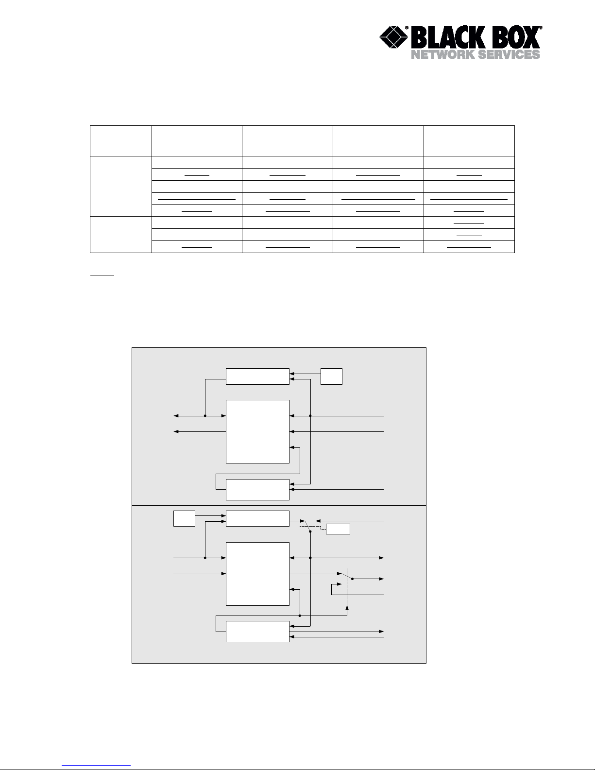
1 SELECTION GUIDE
2
2 wire (2,3Mb)
4 wire (2,3 Mb or 2x2,3Mb)
E1
Nx64/RS232
Single Ethernet Port
Multi-Service E1 - Nx64 - RS232
Point to Point
Point to Multipoint
FXS (only with optional board)
FXO (only with optional board)
Localy Powered - 48V-DC
Remotely powerable
Console Management
SNMP Management
(through management module)
Telnet Management
(through management module)
MDS921AE-E1-R2
MDS923AE-V35X21-R2
MDS923AE-V35X21-MP-R2
MDS923AE-E1-MP-R2
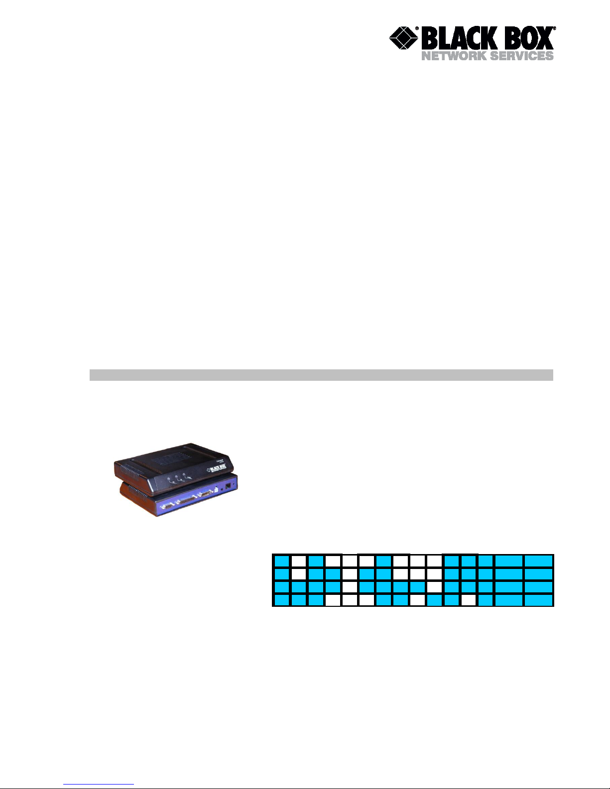
DESKTOP (TELCOLINK), E1, Nx64, V24, Ethernet Bridge
Page 9

TELCOLINK DT - AccessDSL NTU User Manual
Version: 2.5 Page 9 of 66
2 PANEL DESCRIPTION
Figure 2-1: Rear Panel
NE
FE
PWR
Figure 2-2: Tabletop Front View
N64/RS232 Sub-D25
female Connector
E1 120 Ohm Sub-D15
male Connector
Monitor Sub-D9
female Connector
Local/Remote
Power Switch
Optional
EarthTerminal
Power Mini-Fit
4 pin Connector
xDSL RJ-45
8 pin Connector
Tricolour
LED for
local
status
Tricolour
LED for
remote
status
Power
LED
Page 10

TELCOLINK DT - AccessDSL NTU User Manual
Version: 2.5 Page 10 of 66
3 CONFIGURATION OPTIONS
The following sections describe the various configuration options. The operating modes for the
NTU are configurable via the V.24 monitor interface on the rear panel as well as from remote
LTU (or NTU) via DSL in case of establishing of the link. The unit has to be configured for local
or remote power switch, placed on the rear panel.
3.1 xDSL
The following two configuration options refer to the xDSL side only and do not affect the E1 and
Nx64/RS232 interface operating mode.
3.1.1 Master / Slave
To start up an xDSL link, one system unit must be configured as master and the other one as
slave, as the link start-up procedure is controlled by the slave. If both system units are
configured as master or both as slave, no start-up will occur.
Normally, the LTU is configured as master (default setting). In addition, it is also possible to set
up an xDSL link with two NTUs, given that one is configured as master and the other one as
slave.
The "Master / Slave" option also affects the EOC related functions. Generally, the master-slave
rights are:
The master unit has local access as well as access to the slave unit. The master / slave,
G.992.1 Annex, Autorestart configuration and some other settings cannot be altered by the
master unit over the xDSL link for safety reasons (thus, default configuration cannot be
loaded remotely, see chapter 7 for details).
LTUs are always delivered as master (factory setting).
NTUs are always delivered as slave (factory setting).
The slave unit has the far end LED always off, whereas the master unit has it always on.
3.1.2 Normal / Dual pair / Multipoint mode
Units with two xDSL interfaces can operate in 2-wire (Normal) or 4-wire (Dual Pair) mode
according to ITU-T G.992.1. To start up an xDSL link, both system units must be set to the
same mode. Rate adaptation is not supported in Dual Pair Mode, so in this mode both system
units must be set to the same base rate.
In Multipoint mode E1 data is multiplexed to two xDSL interfaces. First n channel time slot is
transmitted through xDSL interface A, while other m channel slots – via xDSL interface B. There
are two sub-modes: PCM30, when TS16 is processed as signaling slot, and PCM31, when
TS16 is considered as channel slot. Multipoint mode is possible for Master only.
3.1.3 Fixed rate / Adaptive setting
In Normal and Multipoint modes Master can operate either in Fixed rate mode (the link will be
established according to Baserate setting if xDSL line conditions allow it) or in rate adaptation
mode (line rate will be selected automatically due to line conditions). In Normal mode Slave is
always in adaptive mode, thus link will be established according to Master settings.
Page 11

TELCOLINK DT - AccessDSL NTU User Manual
Version: 2.5 Page 11 of 66
Rate adaptation is not supported in Dual Pair Mode, so in this mode both system units must be
set to the same base rate.
3.2 E1-Interface (2 Mbit/s G.703 / G.704)
The following configuration options refer to the E1 side only and do not affect the xDSL
operating mode.
3.2.1 Framing
3.2.1.1 Transparent Mode
In the transparent mode, the E1 data will be transmitted without any changes, whereas in the
framed mode the frame / multiframe alignment words and eventually the CRC4 bits are
searched for by the E1 framer.
The “CRC4” option is not relevant in the transparent mode.
Transparent mode is not supported in Multiservice and Multipoint modes.
3.2.1.2 Framed Mode ITU-T G.704
In the framed mode (framing according to ITU-T Rec. G.704), the incoming E1 data stream
passes through an E1 framer before entering the xDSL section. On the other side, the E1
data stream received from the xDSL section first passes through the E1 framer before being
transmitted to the E1 network.
The E1 framer operates in the CCS mode. Time slot 16 is fully transparent (except Multipoint
PCM30 mode).
Consider the “CRC4” option when operating in the framed mode.
3.2.2 CRC4 Option
If operating in the framed mode, the “CRC4” option can be used to adapt the LTU to specific E1
network requirements:
If enabled:
o the E1 framer will synchronize on CRC4 multiframes and CRC4 errors (detected
in the incoming stream) will be reported;
o the E1 framer regenerates the CRC4 multiframe alignment and checksum words
in the outgoing E1 signal. The A-Bit is set to 0 and the national bits (Sa-Bits) fully
transparent (except Multipoint mode).
If disabled, the E1 framer will synchronize on basic frames only and no CRC4 errors will be
reported. Time slot 0 is fully transparent, i.e. the A-Bit and all national bits (Sa-Bits) are fully
transparent (except Multipoint mode).
3.2.3 E-bit Insertion
If operating in the framed mode and “CRC4” option is enabled, the “EBIT” option can be used to
adapt the LTU to specific E1 network requirements:
If the automatic E-Bit generation is enabled, detected CRC4 errors will cause the assertion
of the E-bits.
If disabled, all the E-Bits are set to ‘1’.
The E-bit insertion option is not relevant in transparent mode or if “CRC4” is disabled.
Page 12
TELCOLINK DT - AccessDSL NTU User Manual
Version: 2.5 Page 12 of 66
3.2.4 AIS Generation
If this option is enabled, an unframed AIS (all 1's) will be transmitted on the E1 side, irrespective
of whether the system is configured in the transparent or framed mode. AIS generation will be
activated on the following conditions:
xDSL link to the remote station is not established (loss of signal or loss of frame alignment
on xDSL side) or
remote station is sending AIS or
AIS-R alarm is active.
If “AIS Generation” is disabled, no signal will be transmitted on the E1 side if any of these three
conditions occurs.
3.2.5 AIS Detection
If “AIS Detection” is enabled, receiving AIS from the E1 side will cause the following actions:
The Non-Urgent alarm will be set active (AIS-S).
AIS will be transmitted to the remote station by AIS-R.
3.2.6 Transmission of TS16
In Normal and Dual Pair Modes E1 data is loaded to xDSL according ITU-T G.991.2. In these
modes TS0 of E1 is mapped to TS0 of xDSL, TS1 to TS1 and etc.
To activate the signaling over TS16 the unit has to be set to the PCM 30 mode. If the unit has
less TS than 16, the last TS is used for signaling if the PCM 30 mode is activated.
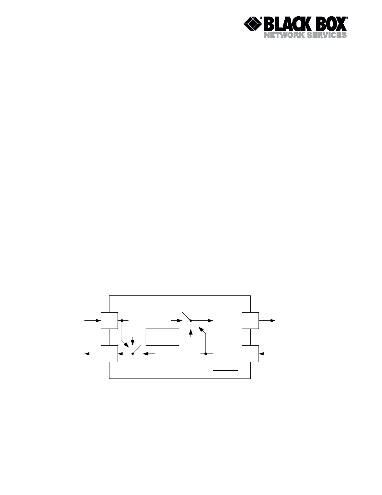
3.2.7 E1 synchronization modes
3.2.7.1 Clocking structure
Internal
Clock
Stuffing
Clock
recovery
xDSL
Tx
xDSL
Rx
E1
Tx
E1
Rx
2 Mbit transmit clock
xDSL recovered clock
E1-side
xDSL side
Figure 3-1: Synchronous Operation
The primary TX clock source for module with E1 interface is:
For Master:
o E1 2 Mbit transmit clock or Internal clock (in case of E1 signal loss).
For Slave:
o E1 2 Mbit transmit clock (if plesiochronous mode is used (“PLL” option at slave
side is on)) or Internal clock (in case of E1 signal loss);
Page 13
TELCOLINK DT - AccessDSL NTU User Manual
Version: 2.5 Page 13 of 66
o xDSL recovered clock (if synchronous mode is used (“PLL” option at slave side is
off)).
The primary RX clock source for module with E1 interface is:
For Master:
o E1 2 Mbit transmit clock (if synchronous mode is used (“PLL” option at master
side is off)) or Internal clock (in case of E1 signal loss);
o xDSL recovered clock (if plesiochronous mode is used (“PLL” option at master
side is on)) or Internal clock (in case of xDSL signal loss).
For Slave:
o xDSL recovered clock or Internal clock (in case of xDSL signal loss).
The clock sources are automatically switched by the microcontroller, depending on the actual
signal and clock status, which is updated every 100 ms.
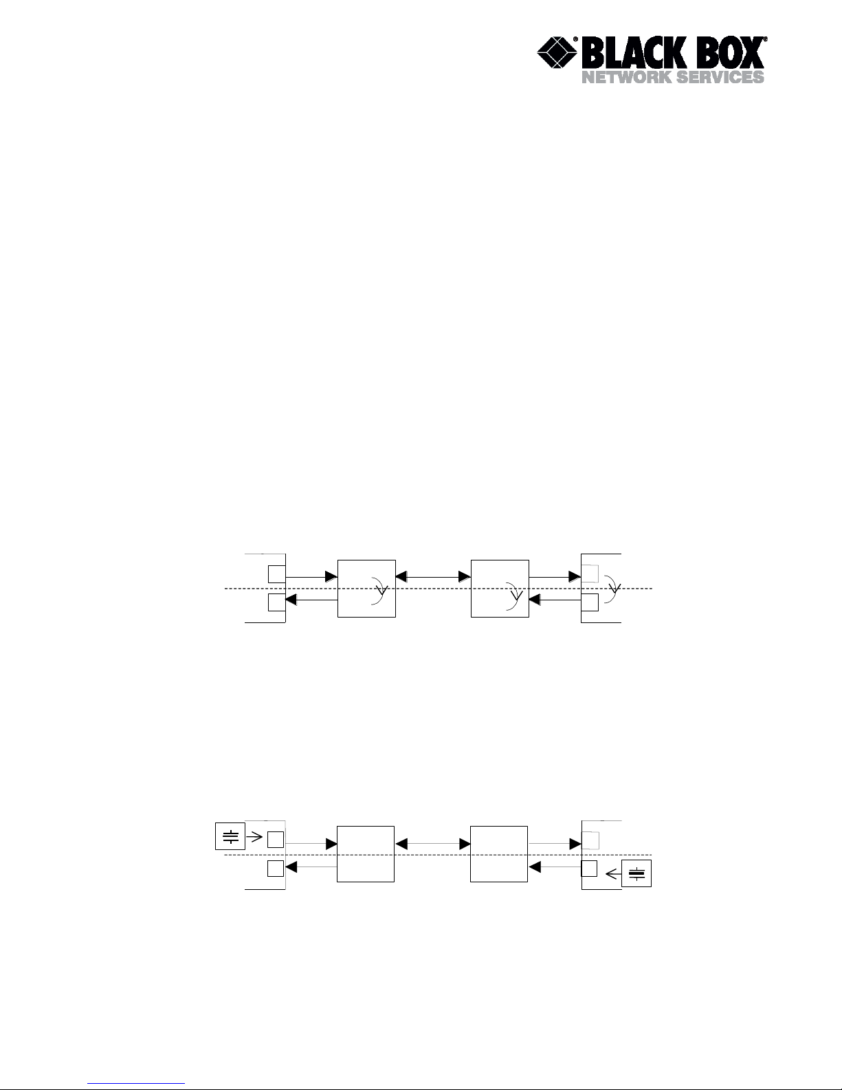
3.2.7.2 Synchronous and plesiochronous operation
Both synchronous and plesiochronous operation modes are possible.
Synchronous operation occurs, when the E1 equipment at one end of the xDSL link uses the
receive clock as transmit clock, as shown below. In this case “PLL” option must be switched off
on both master and slave sides.
E1 NTU /
LTU
Tx
Rx
2048 kHz Clock
E1 Equipment
xDSL Channel
Tx
Rx
E1 Equipment
E1 NTU /
LTU
Master
Slave
Figure 3-2: Synchronous Operation
Plesiochronous operation occurs, when the E1 equipment at both ends of the xDSL link has its
own clock generator, as shown below. In this case “PLL” option must be switched on both
master and slave sides.
E1 NTU /
LTUTxRx
2048 kHz Clock
E1 Equipment
xDSL Channel
TxRxE1 Equipment
E1 NTU /
LTU
Master
Slave
2048 kHz Clock
Figure 3-3: Plesiochronous Operation
Warning:
Do not configure the E1 interfaces at both ends to use the receive clock as
Page 14

TELCOLINK DT - AccessDSL NTU User Manual
Version: 2.5 Page 14 of 66
transmit clock except if one xDSL equipment is an LTU using the "External
Clock" option. Otherwise there will be no defined clock.
N o t e :
O r i o n 1 r e p e a t e r s s u p p o r t o n l y
s y n c h r o n o u s o p e r a t i o n . T o i n c r e a s e
s y s t e m
p e r f o r m a n c e u s e s y n c h r o n o u s m o d e
f o r m a s t e r a n d s l a v e i f r e p a t e r s a r e
u s e d .
Page 15

TELCOLINK DT - AccessDSL NTU User Manual
Version: 2.5 Page 15 of 66
3.3 Nx64/RS232 Interface (DCE)
The following configuration options refer to the Nx64/RS232 (V.35/V.11/V.28/RS232 – SW
configurable) side only and do not affect the xDSL operating mode.
3.3.1 Nx64/RS232 Services
One can choose between three available services:
E1 only: With this service mode, the Nx64 interface is shut down. No payload data is
transferred to/from Nx64 transceiver.
Nx64 only: With this service mode, the E1 transceiver is shut down or is sending AIS. No
payload data is transferred to/from E1 transceiver.
Multiservice Nx64 & fE1: With this service mode, the available xDSL payload is divided into
Nx64 (or RS232) payload and E1 payload. The Nx64 payload always starts at timeslot 1
upwards, skipping timeslot 16 up to timeslot 31, and then using timeslot 16 and at last
timeslot 0. The E1 payload follows after the last used Nx64 timeslot. The RS232 payload
starts at timeslot that is defined by “RS232SLOT” command. For data rates from 110 to
38400 bps RS232 payload occupies one timeslot. For data rates 57600 and 115200 bps
RS232 payload occupies 2 and 3 timeslots accordingly.
3.3.2 Nx64/RS232 Interface Types
The following interface types/data rates are supported (SW configurable):
V.35 / 64…2048 kbps;
V.11 (V.36 or X.21, cable selectable) without termination / 64…2048 kbps;
V.11 (V.36 or X.21, cable selectable) with termination / 64…2048 kbps;
V.28 (synchronous) / 64 and128 kbps;
RS232 (asynchronous) / 110, 150, 300, 600, 1200, 2400, 4800, 9600, 19200, 38400, 57600
and 115200 bps.
3.3.3 Nx64 Clock Directions (V.35, V.11 and V.28 only)
There are two options available:
codirectional: Transmit clock and transmit data have same directions, i.e. both are inputs to
the modem at signal number 113 (clock) and 103 (data).
contradirectional: Transmit clock and transmit data have opposite directions, i.e. transmit
clock is output from modem at signal number 114 and transmit data is input to the modem at
signal number 103.
3.3.4 Nx64 Clock Modes (V.35, V.11 and V.28 only)
The following table shows different combinations of clock modes, some of which are invalid.
There are three possible DCE clock modes:
from E1: This clock mode is active when the E1 interface is active.
external: In this clock mode, the DCE is clock slave and has its PLL on the transmit side
(from Nx64 to the xDSL interface) is on.
internal: In this clock mode, the DCE is clock master and the PLL is off, generating a
2048 kHz clock from the internal oscillator directly.
Page 16
TELCOLINK DT - AccessDSL NTU User Manual
Version: 2.5 Page 16 of 66
Service
DTE
Clock Mode
DCE
Clock Mode
DCE
Clock Direction
xDSL
Clock Mode
Nx64 only
Slave
internal
don’t care
Master
Slave
external
don’t care
Slave
Master
external
codirectional
Slave
Master don’t care
external
contradirectional
Master don’t care
Master
don’t care
don’t care
Master
Nx64 & fE1
Slave
from E1
don’t care
Master
Slave
from E1
don’t care
Slave
Master
don’t care
don’t care
don’t care
Note: Invalid clock modes are ruled out.
3.3.5 Nx64 Block Diagram
The following block diagram shows the receive and transmit path separately. Each direction
possesses a FIFO buffer and a PLL.
Figure 3-4: Nx64 Block Diagram
Rx
FIFO
Rx Framer
RxClk_xDSL
RxData_xDSL
Rx PLL Osc.
FIFO Enable
RxClk_Nx64
RxData_Nx64
RxSync_xDSL
Tx
FIFO
Tx Framer
TxClk_xDSL
TxData_xDSL
Tx PLLOsc.
FIFO Enable
TxClk_Nx64
TxData_Nx64
TxSync_xDSL
TxClk_E1
TxSync_E1
TxData_E1
Service
Page 17
TELCOLINK DT - AccessDSL NTU User Manual
Version: 2.5 Page 17 of 66
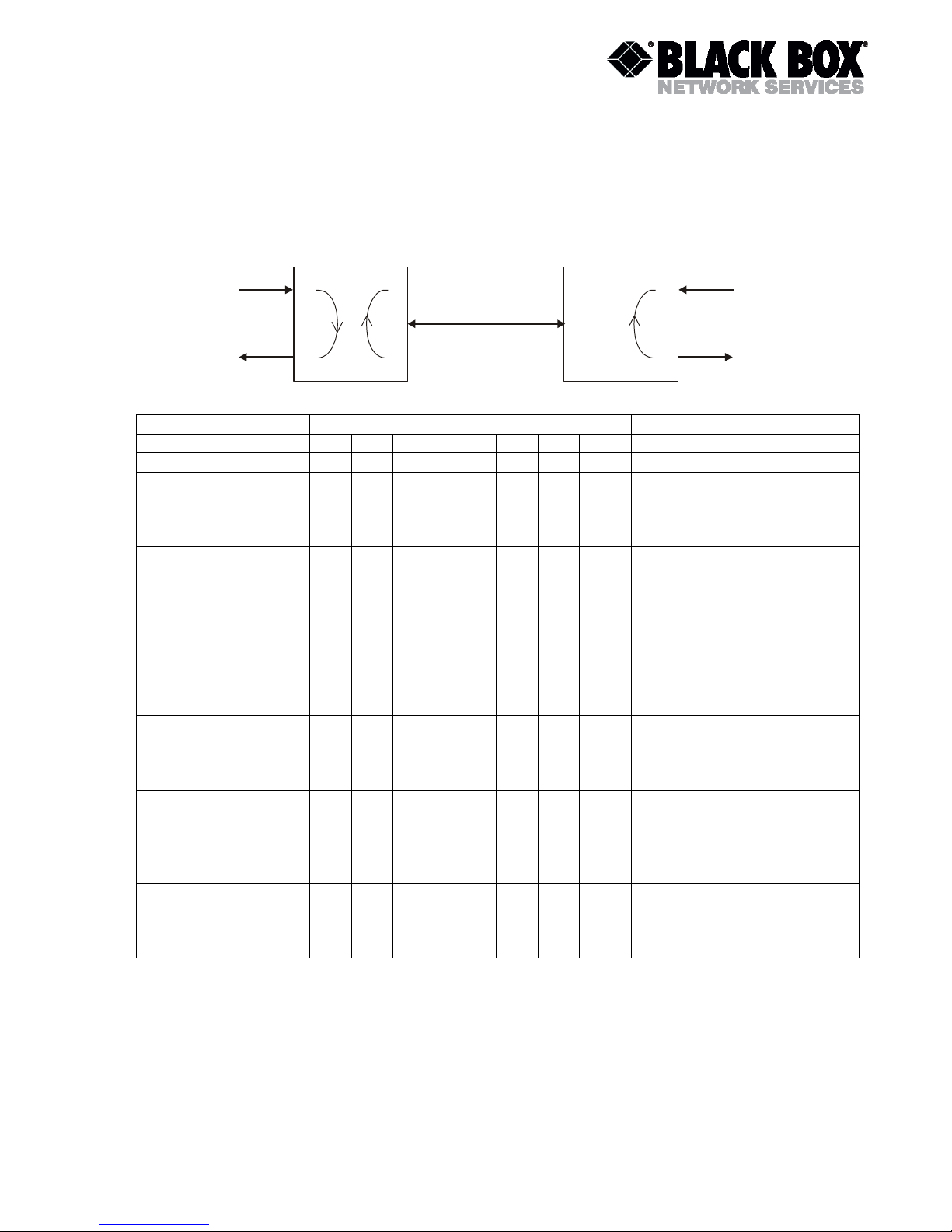
3.3.6 Automatic V.54 loops
System supports V.54 loops, managed by 140-142 lines. Supporting of V.54 loops is SW
programmable.
Tx
TxRxRxLoop 1 Loop 1Loop 2
xDSL
Slave Master
Master
Slave
State Name
RL
LL
TI
RL
LL
TI
DSR
State Description
Normal
1 1 1 1 1 1 0
Data Transmission
Loop1 at Master Side
(Setting by terminal
command)
1 1 0 1 1 1 0
TX Data is looped back to RX
at Nx64 Master Network
Interface. LOOP1 alarm is
active on Master side.
Loop2 (Setting by
terminal command)
1 1 0 1 1 0 1
Data from DSL is looped
back towards Master side in
Slave DSP (Core loopback).
LOOP2 alarm is active on
Master and Slave sides.
Loop1 at Slave Side
(Setting by terminal
command)
1 1 1 1 1 0 0
TX Data is looped back to RX
at Nx64 Slave Network
Interface. LOOP1 alarm is
active on Slave side.
Automatic Loop1
setting at Master side
(activated by LL line
on Master interface)
1 0 0 1 1 1 0
TX Data is looped back to RX
at Nx64 Master Network
Interface. LOOP1 alarm is
active on Master side
Automatic Loop2
(activated by RL line
on Master interface)
0 1 0 1 1 0 1
Data from DSL is looped
back towards Master side in
Slave DSP (Core loopback).
LOOP2 alarm is active on
Master and Slave sides.
Automatic Loop1
setting at Slave side
(activated by LL line
on Slave interface)
1 1 1 1 0 0 0
TX Data is looped back to RX
at Nx64 Slave Network
Interface. LOOP1 alarm is
active on Slave side.
Page 18
TELCOLINK DT - AccessDSL NTU User Manual
Version: 2.5 Page 18 of 66
3.4 Test Loops
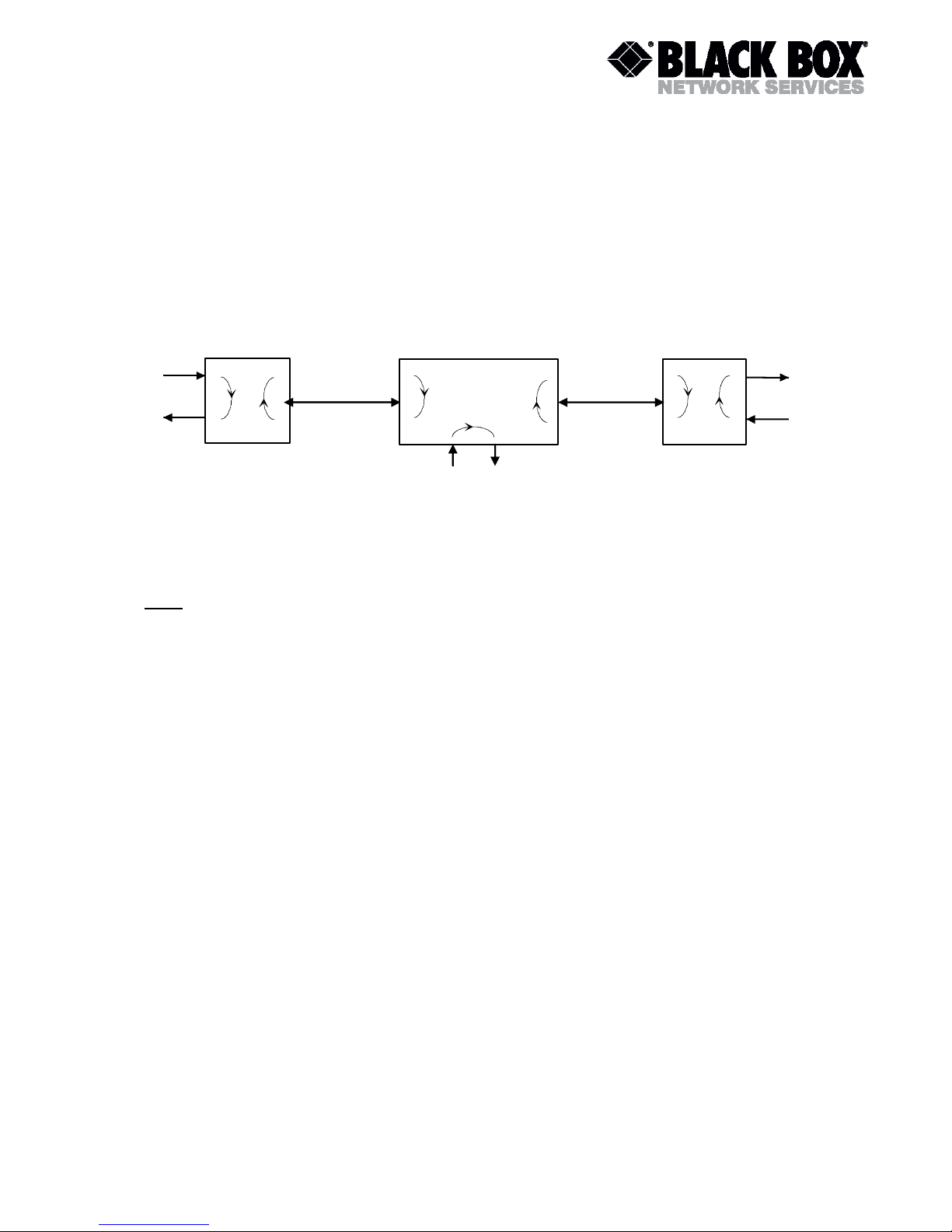
3.4.1 Standard Test Loops
The test loops can be activated via the monitor interface.
Figure 3-5: standard Test Loops
Note:
On the slave side, Loop 1 can be activated locally, Loop 2 can be activated locally or remotely
by the master (LOOP2R command). Loop 1 and Loop 2 on slave can be activated from master
via virtual terminal connection (see CONNECT command description).
Both the NE LED on the slave and the FE LED on the master will be lit amber when Loop2 is
active on slave unit.
At the regenerator point Loop2 on N-side can be activated locally or remotely by the master
(LOOP2R command). Loop 2 on C-side and Loop1 can be activated locally or remotely by the
master via virtual terminal connection (see CONNECT command description and Repeater
Manual).
Both the NE LED on the regenerator and the FE LED on the master will be lit amber when
Loop2 is active.
On the master side, Loop 1 and Loop2 can only be activated locally. The NE LED will be lit
amber when Loop 1 or 2 is active.
3.4.2 Analog Loop Back
To test the Black Box Network Services equipment itself, the Analog Loop Back can be used.
To perform this test, the xDSL - cable has to be disconnected from the unit and the test can be
activated with the appropriate monitor command (see chapter 'Black Box Network Services
Monitor').
During the Analog Test Loop, the xDSL-receiver part receives the transmitted signal of its own
transmitter due to the impedance mismatch in the xDSL-line transformer.
All data of the user interface is looped back according to the UIF and its settings.
An Analog Loop Back causes a non-urgent alarm.
Master
Slave
N-side xDSL
Channel
Loop 1 Loop 2
Loop 2 Loop 1
TX
TX
RX
RX
Repeater
Loop 2 N
C-side xDSL
Channel
Loop 1
E1 interface
Loop 2 C
Page 19

TELCOLINK DT - AccessDSL NTU User Manual
Version: 2.5 Page 19 of 66
4 PERFORMANCE MONITORING
The transmission performance of an xDSL link can be monitored in two different ways. The
xDSL signal quality is typically used during installation and maintenance procedures, whereas
the G.826 error performance parameters are intended to be used for long-term evaluation of
operating xDSL links. Refer also to the “SQ” and “G826” monitor commands described in the
“Black Box Network Services Monitor” section.
4.1 G.826 Performance Monitoring
The G.826 error performance parameters provide quantitative performance information of a
specific loop. They are intended to be used for long-term evaluation of operating xDSL links.
The evaluation of the G.826 error performance parameters is based on CRC (Cyclic
Redundancy Check) error detection:
Slave
CRC4
CRC6
TX
RX
E1
Test
Gen.
CRC4/E-bit
G.826
Evaluation
Gen.
Test
CRC6/FEBE
xDSL
Channel
Master
CRC6
CRC4
Test
Gen.
CRC4/E-bit
G.826
Evaluation
Gen.
Test
CRC6/FEBE
TX
RX
E1
Figure 4-1: G.826 Performance Evaluation
CRC generation and detection on the LTU/NTU are handled separately for the E1 side and the
xDSL side, while on the ADD-DROP Repeater CRC generation and detection are handled
separately for the E1 side and both xDSL sides.
On the E1 side, four CRC4 check bits are generated per sub-multiframe (SMF) and compared
with the corresponding CRC4 bits in the following SMF. If they do not match, the CRC4 error
counter is incremented. The opposite station is informed of detected CRC4 errors by setting Ebits in the transmitted frames. At the same time, the E-Bits from the opposite station are
counted and can be used for performance monitoring.
Similarly, on the xDSL side, six CRC6 check bits are generated per xDSL frame for each
channel and direction. For signaling detected block-errors in the return direction, the FEBE-bits
are used. The HDSL G.826 performance of the opposite unit is calculated according to these
FEBE-bits.
CRC6 errors are used by software to count the block-errors of the respective xDSL channel and
to evaluate its error performance according to ITU-T Rec. G.826.
For the E1 interface, calculations according to G.826 are only possible in the framed mode with
CRC4 option enabled. In framed mode with CRC4 option disabled only FAS-errors are
detected.
The estimation of a bit-error rate is not within the scope of the G.826 calculations.
Page 20

TELCOLINK DT - AccessDSL NTU User Manual
Version: 2.5 Page 20 of 66
5 ALARMS
5.1 General
This chapter describes a possible implementation for the alarm signalization.
5.2 LEDs
The two NTU LEDs 'far end (FE) status' and 'near end (NE) status' are used to display normal
operation condition and alarm condition. Each LED can be green, amber or red when lit
according to the following table. The third LED is used for power representation.
NE LED is responsible for local status of N-side and E1 interfaces, while FE LED is responsible
for local status of C-side interface.
5.2.1 Status LEDs (except Multipoint Mode)
Status
Local (NE) LED
Remote (FE) LED
LTU Power failure
Off
off
Hardware - / Software failure
Blinking Red
off
No EOC connection established
On
red
Normal operation local
Green
don’t care
Normal operation remote
Don’t care
green
xDSL framer synchronizing
Blinking Green/Amber
don’t care
xDSL training
Blinking Amber
don’t care
Minor alarm local
Amber
don’t care
Minor alarm remote
Don’t care
amber
Major alarm local
Red
don’t care
Major alarm remote
Don’t care
red
5.2.2 Status LEDs Multipoint Mode
Status
Local (NE) LED
Remote (FE) LED
Power failure
Off
off
Hardware - / Software failure
Blinking Red
off
No EOC connection established
On
red
Normal operation local
Green
don’t care
Normal operation remote
Don’t care
green
Minor alarm local or one channel
major alarm local
Amber
don’t care
Minor alarm remote or one
channel major alarm remote
Don’t care
amber
Both channel major alarm local
Red
don’t care
Both channel major alarm remote
Don’t care
red
Page 21

TELCOLINK DT - AccessDSL NTU User Manual
Version: 2.5 Page 21 of 66
5.2.3 Local LED - Alarm Conditions
5.2.3.1 Local (NE) LED
An alarm condition is displayed with the Local LED if one of the following conditions occurs:
Major alarm (red):
Hardware or software failure (blinking)
loss of signal / frame alignment on the xDSL side
xDSL block-error-rate according G.826 30% (BER-H)
E1 block-error-rate according G.826 30% (BER-S)
Minor alarm (amber):
loss of signal on the E1 side (LOS-S)
loss of frame alignment on the E1 side (LFA-S)
Segment defect alarm (SEGD)
receiving AIS on E1 side (AIS-S)
either Loop 1, Loop 2 is activated
Analog Loopback is activated
Spectrum Transmission activated
Displaying a major alarm has a higher priority than displaying a minor one, i.e. an amber alarm
will be “overwritten” by a red alarm.
5.2.3.2 Remote (FE) LED
The remote LED is an image of the local LED of the remote station (see previous LED-table for
exceptions).
5.3 Alarm Relays NTU
5.3.1 Implementation
The two alarm relays "Major" and "Minor" are located on the NTU board.
5.3.2 Relay - Alarm Conditions
Major alarm:
At least one of the NTU LEDs displays a red alarm
Power failure of the NTUs
Minor alarm:
At least one of the NTU LEDs displays an amber alarm and none - a red alarm
Power failure of the LTUs
Page 22

Page 23

TELCOLINK DT - AccessDSL NTU User Manual
6 NTU POWER CONCEPT
Each NTU is fed via the power supply Molex connector on the rear panel with 48 VDC. The NTU
converts these voltages to its onboard supply with its DC/DC converter.
In case of a failure of the NTU's onboard power supply, all LEDs on the front-panel will be
extinguished.
Units which support remote power can be powered remotely via xDSL. In case of remote powering
wetting current acceptance should be switched off (remove jumpers -see figure below).
Figure 6-1: NTU Wetting current jumper locations
Wetting
current
acceptance
Page 24

TELCOLINK DT - AccessDSL NTU User Manual
Version: 2.5 Page 24 of 66
7 MONITOR
7.1 General
The module can be connected to a terminal or a PC (with terminal emulation) in order to monitor
relevant events and to display additional information such as the signal quality of the xDSL link or
the G.826 error performance parameters. In addition, full system configuration and fault localization
can be done over the monitor interface
The terminal for monitoring should be VT100 compatible and configured as follows:
9600 baud, asynchronous
8 bits, no parity, one stop bit
no new line on carriage return (i.e. no line feed on carriage return)
7.2 Structure & Organization
The structure and organization of the Black Box Network Services monitor is adapted to ITU-T
Recommendation M.3400 for TMNs with its five sub-sets.
Sub-set
Short-form
Performance management
PM
Fault and maintenance management
FMM
Configuration management
CM
Accounting management
AM
Security management
SM
As Black Box Network Services does not support accounting management AM is not in the monitor's
main menu.
At any time, the <H> (“Help”) command shows and explains the available commands and their
parameters.
The prompt on the screen consists of:
a master/slave or repeater (CO - central office, CP - customer premise, RR - repeater) indication
the slot-number <SN> indication or the repeater address indication
the short form of the specified sub-set menu.
For example: “CO_04_FMM>”.
“RR_04_FMM>”.
Note: Repeater address is calculated as repeater position (starting from CO side) in the xDSL chain
plus 2. Thus the repeater nearest to CO side has address 03, second one – 04, etc.
7.2.1 CLI Timeout
If the CLI interface receives no valid character during 5 minutes, the unit will close the active
session.
Page 25

TELCOLINK DT - AccessDSL NTU User Manual
Version: 2.5 Page 25 of 66
7.2.2 Password protection and access rights
There are two access levels to the system: Administrator (username: ADMIN) end User (username:
USER).
All the commands are available for Administrator while Configuration commands are not accessible
by User.
If administrator password does not set then entering to main menu happens without password
request. In this case Administrator access rights are granted.
If Administrator password is set then system prompts for Username:
username :
and then
password :
Username field is fixed (only ADMIN and USER names are permitted).
7.2.3 Command set tree for Normal and Dual modes (* - Administrator access only)
Main Menu
Performance
Fault and Maintenance
Configuration
Security
G826
SQ
CONFIG
PSW ADMIN*
G826 C
STARTUP*
HW
PSW USER*
G826 E1
STATUS
TSSHOW
G826 E1 C
ALARM
G704*
RESETG826*
ALARM T
CRC4*
HIST*
TLM
EBIT*
RESETHIST*
RESETTLM*
AISGEN*
DATE*
TLMCONF*
AISDET*
TIME*
TLMSET*
PCM*
LOOP1*
IDLECAS*
LOOP2*
IDLEPAT*
STARTAL*
SIGSLOT*
RESTART*
SERVICE*
SPECTRUM*
TYPE*
ACO*
BITRATE*
RESET*
CLOCKDIR*
AUTOLOOP*
SLOTUSAGE*
MODE*
MASTER*
PLL*
RS232SLOT*
RS232BITS*
RS232RATE*
RS232ERATE*
AUTORST*
BASERATE*
ADAPT*
SETADDR*
SCALE*
DEFAULT*
ANNEX*
ID*
SOM*
Page 26

TELCOLINK DT - AccessDSL NTU User Manual
Version: 2.5 Page 26 of 66
Figure 7-1: Command Set Tree (Normal/Dual Pair Modes)
7.2.4 Command set tree for Multipoint mode (* - Administrator access only)
Main Menu
Performance
Fault and Maintenance
Configuration
Security
G826
SQ
CONFIG
PSW ADMIN*
G826 C
STARTUP*
HW
PSW USER*
G826 E1
STATUS
TSSHOW
G826 E1 C
ALARM
CRC4*
RESETG826*
ALARM T
EBIT*
HIST*
TLM
AISGEN*
RESETHIST*
RESETTLM*
AISDET*
DATE*
TLMCONF*
PCM*
TIME*
TLMSET*
PAYLOAD*
LOOP1*
IDLECAS*
LOOP2*
IDLEPAT*
STARTAL*
SIGSLOT*
RESTART*
MODE*
SPECTRUM*
PLL*
ACO*
AUTORST*
RESET*
BASERATE*
ADAPT*
SETADDR*
SCALE*
DEFAULT*
ANNEX*
ID* SOM*
Figure 7-2: Command Set Tree Multipoint Mode
7.2.5 Main Menu
MODEL SA-PAM-SAN-E1B/N64-MP,V34
HW D0
SW 3.0.V4.N.5 / R308_2
SW-DATE Nov 09 2006
ID
RUNS 0000d 00:01:03
ALARM URGENT
STATUS LINK DOWN
MODEL-DESC. Black Box Network Services Tabletop Dual E1 / Nx64 120 Ohm
Copyright (C) 2006 by Black Box Network Services
------------- Main Menu -----------------
1. Performance management (PM)
2. Fault and maintenance management (FMM)
3. Configuration management (CM)
4. Security management (SM)
6. Exit
-----------------------------------------
CP_MM>Select [1..6]:
Page 27

TELCOLINK DT - AccessDSL NTU User Manual
Version: 2.5 Page 27 of 66
To select the sub-menus type 1 to 6.
Note: Each command must be terminated by a carriage return.
7.2.6 Dual Channel SYNTAX
If a Dual channel unit works in multipoint mode and the parameter can be entered for channel A or B
the command syntax can vary. Please use the H command to check the right syntax.
Example:
Normal mode: BASERATE 31
Multipoint mode: BASERATE A 12
7.2.7 Common Commands
Common commands are available in every sub menu.
7.2.7.1 HELP Command
By typing the letter "H" followed by [ENTER], all available commands of the actual sub menu are
displayed.
7.2.7.2 MAIN Command
By typing the letter "M" followed by [ENTER], you return to the Main Menu Screen.
7.2.7.3 CONNECT Command
SYNTAX: CONNECT [n] or CO [n]
The CONNECT command opens a virtual terminal connection to the remote unit, i.e. characters
received at the local unit's V.24 interface are sent to the remote unit, and characters (screen
messages) sent from the remote unit are transmitted back to the local unit's V.24 interface.
During a virtual terminal session, the local unit is not available any more, unless you close your
virtual terminal connection by typing the DISCONNECT command or by selecting "Exit" on the Main
Menu Screen (of the remote unit).
Some commands will be unavailable from a virtual terminal connection for safety reasons.
Add the parameter “R” to connect to the remote unit (i.e. LTU or NTU) or type the repeater number
(1 to 14) instead of “R” to connect to the selected repeater (this is only possible from master side).
7.2.7.4 DISCONNECT Command
SYNTAX: DISCONNECT or DIS
The DISCONNECT command closes the virtual terminal connection to the remote unit.
Page 28

TELCOLINK DT - AccessDSL NTU User Manual
Version: 2.5 Page 28 of 66
7.2.8 Performance management PM
Performance management activated
Enter <M> to return to MAIN, or <H> for HELP information
Type <H> and the monitor lists all available commands in the performance sub-menu.
7.2.8.1 G826 Command
SYNTAX: G826 or G
The G826 command displays the ITU-T G.826 error performance on xDSL line side:
CO_01_PM> G826
G.826 Error Performance : CRC6-A CRC6-B
Errored blocks : 00000000 00000000
Errored seconds : 00000000 00000000
Severely errored seconds : 00000000 00000000
Background block errors : 00000000 00000000
Available time : 00624483 00624483
Unavailable time : 00000024 00000024
CP_PM>
Option:
C Updates the G.826 parameters continuously
Definitions:
1. CRC6-A: Cyclic redundancy check indicating errored blocks received on the local xDSL side.
2. CRC6-B: Far end block error indicating errored blocks received on the remote xDSL side.
3. Errored block (EB): A block in witch one or more bits are in error.
4. Errored seconds (ES): A one second period with one or more errored blocks. SES defined below
is a subset of ES.
5. Severely errored second (SES): A one second period which contains >=30% errored blocks.
6. Background block error (BBE): An errored block not occurring as part of an SES.
Note: In Multipoint and Dual Pair modes represent data for both xDSL interfaces.
7.2.8.2 G826 E1 Command
SYNTAX: G826 E1 or G E1
The G826 E1 command displays the ITU-T G.826 error performance parameters on the E1 2Mbit/s
side. This command is only available if framed mode is enabled.
If CRC4 mode is on, the following parameters are displayed:
CP_PM>G826 E1
---------------------------------------------------------------------G.826 Error Performance : CRC4 E-Bit
---------------------------------------------------------------------Errored blocks : 00000000 00000000
Errored seconds : 00000000 00000000
Severely errored seconds : 00000000 00000000
Background block errors : 00000000 00000000
Page 29

TELCOLINK DT - AccessDSL NTU User Manual
Version: 2.5 Page 29 of 66
Available time : 00000000 00000000
Unavailable time : 00000135 00000135
----------------------------------------------------------------------
CP_PM>
If CRC4 detection mode is off, the following parameters are displayed:
CP_PM>G826 E1
---------------------------------------------------------------------G.826 Error Performance : FAS
---------------------------------------------------------------------Errored blocks : 00000000
Errored seconds : 00000000
Severely errored seconds : 00000000
Background block errors : 00000000
Available time : 00000000
Unavailable time : 00000051
----------------------------------------------------------------------
CP_PM>
Option:
C Updates the G.826 E1 parameters continuously
Definitions:
1. CRC4: Cyclic redundancy check indicating errored sub-multiframes received on the local 2Mbit/s
E1 side.
2. E-bit: CRC-4 indication bit indicating received errored sub-multiframes on the 2Mbit/s E1 remote
side.
3. FAS: Errored Frame Alignment Signal received on the 2Mbit/s E1 side. The criteria for severely
errored seconds (SES) are 28 FAS-Errors per second. (In accordance to G.821)
7.2.8.3 RESETG826 Command
SYNTAX: RESETG826 or RG
The RESETG826 command sets the G.826 error performance parameters back to zero.
CO_PM>RESETG826
G.826 error performance parameter reset
CO_PM>
7.2.8.4 HIST Command
SYNTAX: HIST [i] [t] or HI [i] [t]
This command displays the history data.
Parameters:
i: D for DSL interface
E for E1 interface
N for Nx64 interface
ETH for Ethernet interface
t: A for
7 for the last 7 days
24 for the last 24 hours
Page 30

TELCOLINK DT - AccessDSL NTU User Manual
Version: 2.5 Page 30 of 66
For the Nx64 interface only the alarm history is available.
Page 31

TELCOLINK DT - AccessDSL NTU User Manual
Version: 2.5 Page 31 of 66
7.2.8.5 RESETHIST Command
SYNTAX: RESETHIST or RH
This command clears the history data.
7.2.8.6 DATE Command
SYNTAX: DATE [date] or DA [date]
Without parameters this command displays current date.
With parameters this command sets the date.
FORMAT: DD/MM/YYYY
7.2.8.7 TIME Command
SYNTAX: TIME [time] or TI [time]
Without parameters this command displays the current time.
With parameters this command sets the running time.
FORMAT: HH:MM:SS
Page 32

TELCOLINK DT - AccessDSL NTU User Manual
Version: 2.5 Page 32 of 66
7.2.9 Fault and maintenance management FMM
Fault and maintenance management activated
Enter <M> to return to MAIN, or <H> for HELP information
Type <H>and the monitor lists all available commands in the fault and maintenance sub-menu.
7.2.9.1 SQ Command
The SQ command allows the user to toggle the signal quality trace on and off:
CO_01_FMM> SQ
signal quality trace on
xDSL SNR: local 38.8 dB, remote 39.0 dB
xDSL SNR: local 41.3 dB, remote 38.8 dB
xDSL SNR: local 38.6 dB, remote 39.0 dB
CO_01_FMM> SQ
signal quality trace off
CO_01_FMM>
Note: Units in Multipoint and Dual Pair modes represent data for both xDSL interfaces.
7.2.9.2 STARTUP Command
SYNTAX: STARTUP or SUP
The STARTUP command allows the user to toggle the startup trace on and off, in order to observe
the LTU / NTU activation state diagram transitions conforming to ITU-T G.991.2.
CO_FMM> STARTUP
xDSL transceiver startup trace on
CO_FMM>
CO_FMM> STARTUP
xDSL transceiver startup trace off
CO_FMM>
Note: Units in Multipoint and Dual Pair modes represent data for both xDSL interfaces.
Page 33

TELCOLINK DT - AccessDSL NTU User Manual
Version: 2.5 Page 33 of 66
7.2.9.3 STATUS Command
SYNTAX: STATUS or ST
The STATUS command displays the actual system status:
CO_FMM>STATUS
---------------------------------------------------------------------Local System Status
---------------------------------------------------------------------LOSD : 1
SEGA : 1
PS : 1
SEGD : 1
Tx power : 07.5 dBm
Rx gain : 07.3 dB
Loop attn.: 00.2 dB
SNR : 35.8 dB
Bitrate : 0648 kbit/s
SRU # : 1
ANNEX : A
---------------------------------------------------------------------CO_FMM>
Definitions:
LOSD:
(Loss of Signal) Indicates the loss of signal from the application
interface. Loss of Signal = 0, Normal = 1.
SEGA:
(Segment Anomaly) Indicates a CRC error on the incoming xDSL
frame. A segment anomaly indicates that a regenerator operating
on a segment has received corrupted data and therefore the
regenerated data is unreliable. CRC Error =0, Normal = 1.
PS:
(Power Status)
SEGD:
(Segment Defect)
Tx power:
Local transmit power in dBm
Rx gain:
Local receiver gain in dB
Loop attn.:
Estimate of the loop attenuation in dB of the actual connection
SNR:
SNR is the ratio of constellation power to equalizer error power
Bitrate:
Bitrate of the actual connection
SRU #:
Number of detected repeater in loop
ANNEX
ITU-T Rec. G.991.2 ANNEX
Note: Units in Multipoint and Dual Pair modes represent data for both xDSL interfaces.
Page 34

TELCOLINK DT - AccessDSL NTU User Manual
Version: 2.5 Page 34 of 66
7.2.9.4 ALARM Command
SYNTAX: ALARM or AL
The ALARM command displays the actual alarm status:
CO_01_FMM> ALARM
---------------------------------------------------------------------Local Alarm Status
---------------------------------------------------------------------LOS-S : off
LFA-S : off
AIS-S : off
AIS-R : off
BER-S : off
DTR-OFF : off
LOS/LFA-H : off
SEGD : off
BER-H : off
LOOP1_E1 : off
LOOP1_Nx64: off
LOOP2 : off
ALB : off
TEST : off
----------------------------------------------------------------------CO_01_FMM>
Options:
T Turns alarm trace on / off
Definitions:
LOS-S:
Loss of signal at subscriber (E1) side
LFA-S:
Loss of frame alignment at subscriber (E1) side
AIS-S:
AIS (Alarm Indication Signal) detected at subscriber (E1) side
AIS-R:
AIS (Alarm Indication Signal) detected at subscriber (E1) side of
remote unit
BER-S:
Excessive Block Error Rate on subscriber side
If CRC4 enabled : BER-S = on if more than 805 CRC4 Errors per
second.
If CRC4 disabled : BER-S = on if more than 28 FAS Errors per
second.
DTR-OFF:
V.35/V.36: DTR input is off
X.21: RTS input is off
LOS/LFA-H:
Loss of signal or frame alignment at xDSL loop
SEGD:
Segment Defect indication
BER-H:
xDSL block-error-rate according G.826 30%
LOOP1_E1:
xDSL test loop 1 active (see section)
LOOP1_Nx64:
xDSL test loop 1 active (see section)
LOOP2:
xDSL test loop 2 active
ALB:
Analog loopback
TEST:
At least one test function is active
Note: Units in Multipoint and Dual Pair modes represent data for both xDSL interfaces.
Page 35

TELCOLINK DT - AccessDSL NTU User Manual
Version: 2.5 Page 35 of 66
7.2.9.5 TLM Command
SYNTAX: TLM or T
This command displays table of repeaters’ external alarm inputs.
CO_FMM>TLM
Distance Ext. Alarm Status
---------------------------REPTR | ALM1 | ALM2 | ALM3 |
---------------------------REPT 1| off | det | on |
REPT 2| - | - | - |
REPT 3| - | - | - |
REPT 4| - | - | - |
REPT 5| - | - | - |
REPT 6| - | - | - |
REPT 7| - | - | - |
REPT 8| - | - | - |
REPT 9| - | - | - |
REPT10| - | - | - |
REPT11| - | - | - |
REPT12| - | - | - |
REPT13| - | - | - |
REPT14| - | - | - |
---------------------------CO_FMM>
Definitions:
Off – no external alarm detected
On – external alarm is active
Det – external alarm have been detected since last clearing of external alarm table
7.2.9.6 RESETTLM Command
SYNTAX: RESETTLM or RT
This command clears the external alarm table.
7.2.9.7 TLMCONF Command
SYNTAX: TLMCONF or TC
This command displays the external alarm config table.
Page 36

TELCOLINK DT - AccessDSL NTU User Manual
Version: 2.5 Page 36 of 66
7.2.9.8 TLMSET Command
SYNTAX: TLMSET [Rn-k] [abc] or TS [Rn-k] [abc]
This command sets the external alarm configuration.
Definitions:
- ignore
RES represents external alarm status in the external alarm table
MIN represents external alarm status in the external alarm table and consider as Minor alarm
MAJ represents external alarm status in the external alarm table and consider as Major alarm
CO_FMM>TLMSET R02-R03 321
Reactions table for distance ext. alarms
---------------------------REPTR | ALM1 | ALM2 | ALM3 |
---------------------------REPT 1| RES | MIN | MAJ |
REPT 2| MAJ | MIN | RES |
REPT 3| MAJ | MIN | RES |
REPT 4| - | - | - |
REPT 5| - | - | - |
REPT 6| - | - | - |
REPT 7| - | - | - |
REPT 8| - | - | - |
REPT 9| - | - | - |
REPT10| - | - | - |
REPT11| - | - | - |
REPT12| - | - | - |
REPT13| - | - | - |
REPT14| - | - | - |
---------------------------CO_FMM>
Definitions:
Rnn exact repeater position (adjust configuration for one repeater) or
Rnn-Rkk repeaters position range (adjust configuration for some repeaters)
Last 3 symbols define configuration of 3 alarm inputs of the repeater(-s):
0 ignore
1 represents external alarm status in the external alarm table
2 represents external alarm status in the external alarm table and consider as Minor alarm
3 represents external alarm status in the external alarm table and consider as Major alarm
Page 37

TELCOLINK DT - AccessDSL NTU User Manual
Version: 2.5 Page 37 of 66
7.2.9.9 LOOP1 Command
SYNTAX: LOOP1 [E/N] [ON/OFF] or L1 [E/N] [ON/OFF]
The LOOP1 command starts the local loopback (see section 3.4.1: Standard Test Loops):
CO_FMM>LOOP1 E ON
Loop 1 on E1 interface on
CO_FMM>
CO_01_FMM> LOOP1 OFF
Loop 1 off
CO_01_FMM>
7.2.9.10 LOOP2 Command
SYNTAX: LOOP2 [n] [ON/OFF] or L2 [n] [ON/OFF]
The LOOP2 command starts the local loopback toward xDSL (see section 3.4.1: Standard Test
Loops):
CO_FMM>LOOP2 R ON
Remote loop activation started
Remote loop on
CO_FMM>
Parameters:
n: L local unit
1..14 repeater number
R remote unit
Note: In the Multipoint mode the LOOP2 command has additional parameters, which assign the
necessary xDSL interface.
7.2.9.11 STARTAL Command
SYNTAX: STARTAL or SAL
The STARTAL command starts the analog loopback:
CO_FMM>STARTAL
Analog loopback started
CO_FMM>
CO_FMM>STARTAL
Analog loopback stopped
CO_FMM>
Notes:
Detach the xDSL line before starting the analog loopback. If the analog loopback is started while
a remote station is attached to the xDSL line, the remote station signal will interfere with the
loopback signal, causing bit errors on the network interface.
Note: In Multipoint mode and for Repeater STARTAL command has a parameter, which assign
necessary xDSL interface.
Page 38

TELCOLINK DT - AccessDSL NTU User Manual
Version: 2.5 Page 38 of 66
7.2.9.12 RESTART Command
SYNTAX: RESTART or RE
By typing RESTART, the actual channel will be restarted.
CO_01_FMM> RESTART
Restarting channel
CO_01_FMM>
Note: In Multipoint mode and for Repeater RESTART command has a parameter, which assign
necessary xDSL interface.
7.2.9.13 SPECTRUM Command
SYNTAX: SPECTRUM or SP
The SPECTRUM command initializes the xDSL analog output for power measurements.
CO_FMM>SPECTRUM
Analog spectrum started
CO_FMM>SPECTRUM
Analog spectrum stopped
CO_FMM>
Note: In Multipoint mode and for Repeater SPECTRUM command has a parameter, which assign
necessary xDSL interface.
7.2.9.14 ACO command
SYNTAX: ACO [ON/OFF]
This command blocks/unblocks alarm relays.
CO_FMM>ACO ON
ACO is ON
CO_FMM>ACO OFF
ACO is OFF
7.2.9.15 RESET Command
SYNTAX: RESET or RST
By typing RESET, the system unit will be restarted.
CO_01_FMM> RESET
System reset
Page 39

TELCOLINK DT - AccessDSL NTU User Manual
Version: 2.5 Page 39 of 66
7.2.10 Configuration management CM
Configuration management activated
Enter <M> to return to MAIN, or <H> for HELP information
Type <H> and the monitor lists all available commands in the configuration sub-menu.
7.2.10.1 CONFIG Command
SYNTAX: CONFIG or C
The CONFIG command displays the configuration of the unit.
Note: After each configuration change, the new configuration is automatically displayed.
7.2.10.2 HW Command
SYNTAX: HW
Display actual hardware configuration.
7.2.10.3 TSSHOW Command
SYNTAX: TSSHOW [A/E/N] or TSS [A/E/N]
This command displays the actual time slots relation for the selected interface.
Parameters:
A relation for DSL A interface;
E relation for E1 interface;
N relation for Nx64 interface.
7.2.10.4 G704 Command
SYNTAX: G704 [ON/OFF]
Set framed mode / transparent mode.
Note: This command is not supported in Multipoint mode.
7.2.10.5 CRC4 Command
SYNTAX: CRC4 [ON/OFF] or C4 [ON/OFF]
Set CRC4 processing on / off
7.2.10.6 EBIT Command
SYNTAX: EBIT [ON/OFF] or E [ON/OFF]
Page 40

TELCOLINK DT - AccessDSL NTU User Manual
Version: 2.5 Page 40 of 66
Set automatic E-Bit insertion on / off
7.2.10.7 AISGEN Command
SYNTAX: AISGEN [ON/OFF] or AG [ON/OFF]
Set AIS generation on / off
7.2.10.8 AISDET Command
SYNTAX: AISDET [ON/OFF] or AD [ON/OFF]
Set AIS detection on / off
7.2.10.9 PCM Command
SYNTAX: PCM [30/31]
This command enables/disables signaling timeslot processing:
Parameters:
[31]: Set signaling timeslot processing off.
[30]: Set signaling timeslot processing on. Signaling slot is transmitted transparently.
7.2.10.10 PAYLOAD Command
SYNTAX: PAYLOAD [a] [b] or PL [a] [b]
This command sets the numbers of channelTS to be transmitted to xDSL interfaces A and B.
7.2.10.11 IDLECAS Command
SYNTAX: IDLECAS [hex] or IC [hex]
This command sets the idle pattern (1..F) for the signaling TS.
7.2.10.12 IDLEPAT Command
SYNTAX: IDLEPAT [hex] or IDP [hex]
This command sets the idle pattern (0..FF) for unused data slot(s).
7.2.10.13 SIGSLOTS Command
SYNTAX: SIGSLOTS [AUTO/a,e] or SS [AUTO/a,e]]
This command sets the signaling slot number of the DSL A and E1 interface.
Valid only for the PCM 30 mode.
Parameters:
Page 41

TELCOLINK DT - AccessDSL NTU User Manual
Version: 2.5 Page 41 of 66
AUTO: standard config (TS16 or last TS if baserate < 16)
a: 1 – 31 for DSL A
e: 1 – 31 for E1/G703
Page 42

TELCOLINK DT - AccessDSL NTU User Manual
Version: 2.5 Page 42 of 66
7.2.10.14 SERVICE Command
SYNTAX: SERVICE [E/N/M] or SRV [E/N/M]
Select one of four available services:
E E1 only
N Nx64 only
M Multiservice Nx64 & fE1 (fractional E1)
7.2.10.15 TYPE Command
SYNTAX: TYPE [n] or TP [n]
This command sets the Nx64 interface type.
Parameters:
0 V.35
1 V.11 (V.36/X.21) without termination
2 V.11 (V.36/X.21) with termination
3 V.28 synchronous
4 RS232 asynchronous
7.2.10.16 BITRATE Command
SYNTAX: BITRATE [n] or BTR [n]
This command sets the Nx64 payload bit rate to [1..32] x 64 kbit/s for V.35 and V.11 or [1..2] x 64
kbit/s for V.28.
Parameters:
n: 1-31 depending on the Nx64 interface type
7.2.10.17 CLOCKDIR Command
SYNTAX: CLOCKDIR [CO/CONTRA] or CD [CO/CONTRA]
This command sets the Nx64 port clock direction to co- or contradirectional.
Parameters:
CO Codirectional uses input line 113 for input data (103) sampling
CONTRA Contradirectional uses output line 114 for input data (103) sampling
Page 43

TELCOLINK DT - AccessDSL NTU User Manual
Version: 2.5 Page 43 of 66
7.2.10.18 AUTOLOOP Command
SYNTAX: AUTOLOOP [ON/OFF] or AUL [ON/OFF]
This command enables/disables the usage of lines 140/141 for The automatic V.54 loop control.
7.2.10.19 SLOTUSAGE Command
SYNTAX: SLOTUSAGE [ON/OFF] or SU [ON/OFF]
This command enables/disables the usage of timeslot 0 for the Nx64 payload when service Nx64
only is selected.
7.2.10.20 MODE Command
SYNTAX: MODE [N/D/M] or MO [N/D/M]
This command sets the operation mode.
Parameters:
N Normal mode
D Dual pair mode
M Multipoint mode
7.2.10.21 MASTER Command
SYNTAX: MASTER [ON/OFF] or MA [ON/OFF]
Set xDSL master/slave mode. One unit must be configured as master, the other as slave.
7.2.10.22 PLL Command
SYNTAX: PLL [ON/OFF
This command enables/disables the PLL on channel A of xDSL port (see section 3.2.7).
7.2.10.23 RS232SLOT Command
SYNTAX: RS232SLOT [n] or RSS [n]
This command assigns the slot [1..31] for RS232 data transmission.
7.2.10.24 RS232BITS Command
SYNTAX: RS232BITS [n] or RSB [n]
This command sets the number the RS232 data bits [7..10].
Page 44

TELCOLINK DT - AccessDSL NTU User Manual
Version: 2.5 Page 44 of 66
7.2.10.25 RS232RATE Command
SYNTAX: RS232RATE [n] or RSR [n]
This command sets the RS232 rate.
Parameters:
N 110, 150, 300, 600, 1200, 2400, 4800, 9600, 14400, 19200, 28800, 38400, 57600,115200
7.2.10.26 RS232ERATE Command
SYNTAX: RS232ERATE [n] or RSR [n]
This command sets the excess rate of the RS232 interface.
Parameters:
1 0 percent
2 0.5 percent
3 1 percent
4 2 percent
Note: for correct data transmission on rate 115200 via RS232 interface two stop bits must be used
AUTORNC
NC
NC
7.2.10.27 ST Command
SYNTAX: AUTORST [ON/OFF] or AR [ON/OFF]
This command enables/disables the restarting of the xDSL channel.
7.2.10.28 BASERATE Command
SYNTAX: BASERATE [n] or BR [n]
This command sets the base xDSL payload rate. This value must be between 3 and 32 and defines
the available 64 kbit/s channels.
7.2.10.29 ADAPT Command
SYNTAX: ADAPT [ON/OFF] or ADP [ON/OFF]
This command enables/disables rate adaption during startup.
Page 45

TELCOLINK DT - AccessDSL NTU User Manual
Version: 2.5 Page 45 of 66
7.2.10.30 SETADDR Command
SYNTAX: SETADDR [n] or SA [n]
This command sets the virtual modem address.
Parameters:
00 Disable “%xx” command for entering NTU (Normal Mode!!!).
01 – 99 Address 1-99
A0-A9 Address 100 -109
B0-B9 Address 110 -119
C0-C7 Address 120 -127
Note: If you entered an address and forgot the value type ECHO and the unit will respond with the
programmed address.
7.2.10.31 SCALE Command
SYNTAX: SCALE [A/B] [n] or SC [A/B] [n]
This command sets output TX power offset from ITU-T value in dBm.
Parameters:
0.0 highly recommended standard operation
-16.0..2.0 with 0.5 increment steps
7.2.10.32 ANNEX Command
SYNTAX: ANNEX [A/B] [A/B/AB] or AN [A/B] [A/B/AB]
Set desired ITU-T Rec. G.991.2 Annex type
Parameters:
A Annex A
B Annex B
AB Annex A_B (autodetect annex type).
7.2.10.33 ID Command
SYNTAX: ID [text]
This command sets a unique identification string printed on the main screen.
Page 46

TELCOLINK DT - AccessDSL NTU User Manual
Version: 2.5 Page 46 of 66
7.2.10.34 SOME Command
SYNTAX: SOM [type]
Parameters:
<no> Show available Operation & Monitoring System
type: Monitoring System type 0-none
1-M2M
7.2.10.35 DEFAULT Command
SYNTAX: DEFAULT [n] or DF [n]
This command sets default configuration. There are two default configurations for multipoint mode
(n=0..1) and six for all other modes (n=0..5).
Factory Default command
CO_CM>DEFAULT F
---------------------------------------------------------------------Local Configuration
---------------------------------------------------------------------2 Mbit/s
Framing : Transparent CRC4 : - E-Bit Insertion : -- AIS Detection : on
AIS Generation : on
xDSL
Mode : Normal Service : E1 only
Master/Slave : Slave PLL : off
Autorestart : on Base Rate : 03-32
Rate Adaption : on Annex : A_B
Power Offset : +00.0 dBm
----------------------------------------------------------------------
7.2.10.35.1 E1 only Normal or Dual Pair mode
DEFAULT 0 1 2 3 4 5
Framing
Transparent
ITU-T G.704
ITU-T G.704
Transparent
ITU-T G.704
ITU-T G.704
CRC4
--
off
on
--
off
on
E-Bit Insertion
--
--
on
--
--
on
AIS Detection
on
on
on
on
on
on
AIS Generation
on
on
on
on
on
on
Mode
* * * * *
*
Master/Slave
Master
Master
Master
Slave
Slave
Slave
PLL
off
off
off
off
off
off
Autorestart
on
on
on
on
on
on
Base Rate
32
32
32
03-32
03-32
03-32
Rate Adaption
off
off
off
on
on
on
Annex
A_B
A_B
A_B
A_B
A_B
A_B
Power Scale
Offset
0 0 0 0 0
0
* not changed
Page 47

TELCOLINK DT - AccessDSL NTU User Manual
Version: 2.5 Page 47 of 66
7.2.10.35.2 Nx64 only Normal or Dual Pair mode
DEFAULT 0 1 2 3 4 5
Interface Type
V.35
V.35
V.35
V.35
V.35
V.35
Bitrate
512 kbit/s
1024 kbit/s
2048 kbit/s
512 kbit/s
1024 kbit/s
2048 kbit/s
Clock Edge
inverted
inverted
inverted
inverted
inverted
Inverted
V.54 Loops
disabled
disabled
disabled
disabled
disabled
Disabled
Clock Mode
internal
internal
internal
remote
remote
Remote
Clock Direction
contradirecti
onal
contradirecti
onal
contradirecti
onal
contradirecti
onal
contradirecti
onal
Contradirecti
onal
Use Timeslot 0
no
no
yes
no
no
Yes
Mode
* * * * *
*
Master/Slave
Master
Master
Master
Slave
Slave
Slave
PLL
off
off
off
off
off
Off
Autorestart
on
on
on
on
on
On
Base Rate
09
17
32
03-32
03-32
03-32
Rate Adaption
off
off
off
on
on
On
Annex
A_B
A_B
A_B
A_B
A_B
A_B
Power Scale
Offset
0 0 0 0 0
0
* not changed
Default values for RS232:
- bits: 8
- rate: 0 (RS232 disabled)
- excess rate transmitter over receiver: 0.0 %
- slot: 31
Page 48

TELCOLINK DT - AccessDSL NTU User Manual
Version: 2.5 Page 48 of 66
7.2.10.35.3 fE1 &Nx64 Normal or Dual Pair mode
DEFAULT
0 1 2 3 4
5
Framing
ITU-T G.704
ITU-T G.704
ITU-T G.704
ITU-T G.704
ITU-T G.704
ITU-T G.704
CRC4
on
on
on
on
on
on
E-Bit Insertion
on
on
on
on
on
on
AIS Detection
on
on
on
on
on
on
AIS Generation
on
on
on
on
on
on
Mode
* * * * *
*
Interface Type
V.35
V.35
V.35
V.35
V.35
V.35
Bitrate
256 kbit/s
512 kbit/s
1024 kbit/s
256 kbit/s
512 kbit/s
1024 kbit/s
Clock Edge
inverted
inverted
inverted
inverted
inverted
inverted
V.54 Loops
disabled
disabled
disabled
disabled
disabled
disabled
Clock Mode
from E1
from E1
from E1
remote
remote
remote
Clock Direction
contradirectio
nal
contradirectio
nal
contradirectio
nal
contradirectio
nal
contradirectio
nal
contradirectio
nal
Use Timeslot 0
--
--
--
--
--
--
Mode
* * * * * * Master/Slave
Master
Master
Master
Slave
Slave
Slave
PLL
off
off
off
off
off
off
Autorestart
on
on
on
on
on
on
Base Rate
32
32
32
03-32
03-32
03-32
Rate Adaption
off
off
off
on
on
on
Annex
A_B
A_B
A_B
A_B
A_B
A_B
Power Scale Offset
0 0 0 0 0
0
* not changed
Default values for RS232:
- bits: 8
- rate: 0 (RS232 disabled)
- excess rate transmitter over receiver: 0.0 %
- slot: 31
Page 49

TELCOLINK DT - AccessDSL NTU User Manual
Version: 2.5 Page 49 of 66
7.2.10.35.4 Multipoint Mode
DEFAULT
0
1
Framing
ITU-T
G.704
ITU-T
G.704
CRC4
on
on
E-Bit Insertion
on
on
AIS Detection
on
on
AIS Generation
on
on
PCM Mode
PCM31
PCM30
Payload
16 15
15 15
Idle pattern
--
0xD
Mode
* * Master/Slave
Master
Master
PLL
off
off
Autorestart
on on
on on
Base Rate
17 16
17 17
Rate Adaption
off off
off off
Annex
A_B A_B
A_B A_B
Power Scale
Offset
0
0
* not changed
7.2.11 Security management SM
Security management activated
Enter <M> to return to MAIN, or <H> for HELP information
Type <H> and the monitor lists all available commands in the configuration sub-menu.
7.2.11.1 PSW Command
SYNTAX: PSW [USER/ADMIN]
This command sets the user/admin password (4-8 characters).
CO_SM>PSW ADMIN
Enter password: ******
Confirm new password: ******
New password was fixed
Page 50

TELCOLINK DT - AccessDSL NTU User Manual
Version: 2.5 Page 50 of 66
8 SOFTWARE UPDATE
8.1 General
The software of the Black Box boards has the possibility for field updates. To do a field update, you
need only a Windows 95/98/NT computer, the Flash Loader program installed, a connection
between the Windows computer and the LTU/NTU Monitor connector and the newest release of the
Black Box software.
8.2 Software download
To update the software on your LTU/NTU you have to run through the following steps:
1. Switch off the power of your LTU/NTU.
2. Connect the LTU/NTU monitor connector with your Windows computer’s RS232 interface.
3. Start the Flash Loader software on your Windows computer
4. Choose Set Loader Communication in the menu Setting. Select the right communication port,
the communication information and press Ok.
Page 51

TELCOLINK DT - AccessDSL NTU User Manual
Version: 2.5 Page 51 of 66
5. Choose Select Device in the Setting menu, select the device AccessDSL and press Ok.
6. Choose the newest software version and press Open.
Page 52

TELCOLINK DT - AccessDSL NTU User Manual
Version: 2.5 Page 52 of 66
7. Execute the command Connect COM in the menu Action.
8. Switch on the power of your LTU/NTU.
9. The following message appears on the screen, then press Ja.
Page 53
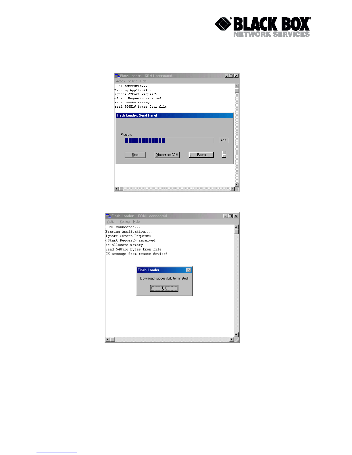
TELCOLINK DT - AccessDSL NTU User Manual
Version: 2.5 Page 53 of 66
10. During the download the FE-LED is green blinking and the NE-LED is amber. On the Windows
screen you see the ongoing download.
11. If the download is successfully finished the Flash Loader program sends the following message:
12. If the download was successful, the LTU/NTU restarts automatically.
Page 54

TELCOLINK DT - AccessDSL NTU User Manual
Version: 2.5 Page 54 of 66
9 CONNECTORS' DESCRIPTION
9.1 xDSL Connector
Front View
RJ45-8
1
8
Pin
Signal
Description
1
NC
Not used
2
Shield
DSL cable shield
3
TXA.a
Loop B, Tip (C-side) (four-wire unit only)
4
LA.a
Loop A, Tip (N-side)
5
LA.b
Loop A, Ring (N-side)
6
TXA.b
Loop B, Ring (C-side) (four-wire unit only)
7
Shield
DSL cable shield
8
NC
Not used
9.2 E1 120 Ohm Connector
1
8
9
15
Pin
Signal
Description
1
Out_Ch1,A
E1 Output → Ch 1 (wire A sym)
2
FPE
Functional Protective Earth (cable shield Out Ch 1)
3
Inp_Ch1,A
E1 Input→ Ch 1 (wire A sym)
4
FPE
Functional Protective Earth (cable shield Inp Ch 1)
5
FPE
- 6 NC
- 7 FPE
8 NC
9 Out_Ch1,B
E1 Output → Ch 1 (wire B sym)
10
NC
11
Inp_Ch1,B
E1Input → Ch1 (wire B sym)
12
NC
-
13
-
15
NC
-
9.3 E1 75 Ohm In / Out Connectors
Type: BNC 75
Optionally equipped for E1 interface with 75
Page 55

TELCOLINK DT - AccessDSL NTU User Manual
Version: 2.5 Page 55 of 66
9.4 Nx64/RS232 DCE Connector
Pin
V.24 (V.35/V.36)
X.21
Direction
ITU-T #
Description
Name
Description
Name 1 - Shield
-
Shield - -
7
102
Signal Gnd
SG
Signal Gnd
G
-
2
103a
Transmit Data (A)
TD(A)
Transmit (A)
Ta
TO DCE
14
103b
Transmit Data (B)
TD(B)
Transmit (B)
Tb
TO DCE
3
104a
Receive Data (A)
RD(A)
Receive (A)
Ra
TO DTE
16
104b
Receive Data (B)
RD(B)
Receive (B)
Rb
TO DTE
4
105a
Request To Send (A)
RTS(A)
Control (A)
Ca
TO DCE
19
105b
Request To Send (B)
RTS(B)
Control (B)
Cb
TO DCE
5
106a
Clear To Send (A)
CTS(A)
Indication (A)
Ia
TO DTE
13
106b
Clear To Send (B)
CTS(B)
Indication (B)
Ib
TO DTE
6
107a
Data Set Ready (A)
DSR(A)
TO DTE
22
107b
Data Set Ready (B)
DSR(B)
TO DTE
20
108a
Data Terminal Ready (A)
DTR(A)
TO DCE
23
108b
Data Terminal Ready (B)
DTR(B)
TO DCE
8
109a
Data Carrier Detect (A)
DCD(A)
TO DTE
10
109b
Data Carrier Detect (B)
DCD(B)
TO DTE
24
113a
Terminal Transmit Clock (A)
TTC(A)
DTE Signal Element Timing (A)
Xa
TO DCE
11
113b
Terminal Transmit Clock (B)
TTC(B)
DTE Signal Element Timing (B)
Xb
TO DCE
15
114a
Transmit Clock (A)
TC(A)
TO DTE
12
114b
Transmit Clock (B)
TC(B)
TO DTE
17
115a
Receive Clock (A)
RC(A)
Signal Element Timing (A)
Sa
TO DTE
9
115b
Receive Clock (B)
RC(B)
Signal Element Timing (B)
Sb
TO DTE
21
140
Remote Loopback
RLB
TO DCE
18
141
Local Loopback
LLB
TO DCE
25
142
Test Mode
TM
TO DTE
Continue:
Pin
V.24 (V.28) synchronous
RS232 asynchronous
Direction
ITU-T #
Description
Name
Description
Name 1 - Shield
7
102
Signal Gnd
SG
Signal Gnd
SGND
21
103
Transmit Data
TD
Transmit Data
TXD
TO DCE
5
104
Receive Data
RD
Clear To Send
CTS
TO DTE
4
105
Request To Send
RTS
Request To Send
RTS
TO DCE
6
107
Data Set Ready
DSR
Data Set Ready
DSR
TO DTE
20
108
Data Terminal Ready
DTR
Data Terminal Ready
DTR
TO DCE
18
113
Terminal Transmit Clock
TTC
TO DCE
25
114
Transmit Clock
TC
Receive Data
RXD
TO DTE
8
115
Receive Clock
RC
Data Carrier Detect
DCD
TO DTE
Page 56

TELCOLINK DT - AccessDSL NTU User Manual
Version: 2.5 Page 56 of 66
9.5 Monitor Interface
5
1
9
6
Pin
Signal
Description
1
FPE
Functional Protective Earth
2
TXD
EIA-232 Transmit Data
3
RXD
EIA-232 Receive Data
4
ALACOM
Common Contact*
5
SGND
EIA-232 Signal Ground
6
ALMAJ_NC
Major Alarm Contact, normally closed*
7
ALMAJ_NO
Major Alarm Contact, normally open*
8
ALMIN_NC
Minor Alarm Contact, normally closed*
9
ALMIN_NO
Minor Alarm Contact, normally open*
9.6 Power Interface
Frontview
Molex-Type Power Connector
4 3
2 1
Pin
Signal
Description
1
-MainsPWR
Negative power supply terminal for mains adapter
2
FPE
Functional Protective Earth
3
NC
-
4
+PWR
Positive power supply terminal
Molex Mini-Fit, 4-pin
Page 57

TELCOLINK DT - AccessDSL NTU User Manual
Version: 2.5 Page 57 of 66
10 TECHNICAL SPECIFICATION
10.1 Interfaces
10.1.1 xDSL Line Interface
Specification
ITU-T G.SHDSL, Reek G.991.2
Option
4-wire Interface (separate Tx and Rx Pairs)
Line Code
TC-PAM
Impedance
135
Transmit Power
13.5 (Annex A) or 14.5 (Annex B) dBm @ 135
Number of Pairs
1 or 2 (option: 2 or 4)
Bit Rate
192 to 2064 kbps
Connector Type
RJ-45, 8 pin
Overvoltage Protection
ITU-T Rec. K.20/K.21
Specification
ITU-T G.SHDSL, Rec G.991.2
Wetting Current
2-4 mA @ 60 V
10.1.2 E1 Line Interface
Specification
ETS 300 166, ITU-T Rec G.703, G.704
Number of Interfaces
1 or 2
Line Code
HDB3
Impedance
either 120 or 75
Jitter
ITU-T Rec G.823, ETSI TS 101 135
Bit Rate
2048 kbit/s ± 50 ppm
Connector Type
either DB15 male (120) or two BNC 75
ESD Protection
8 kV (Air discharge)
10.1.3 V.35 DCE User Interface
Specification
ITU-T Rec V.35/V.36/X.21/V.24/V.28/EIA-232
Number of Interfaces
1
Connector Type
DB25 female
Bitrate
1…32 x 64 kbps (synchronous);
4800…115200 bps (asynchronous)
10.1.4 Monitor Interface
Specification
EIA-232 / V.28
Data Rate
9600 baud, asynchronous
Protocol
8 bit, no parity, 1 stop bit no linefeed with carriage return
XON/XOFF enabled
Signal Level
V.28 on DB9 female connector
Connector Type
DB9 female connector
10.2 Power Supply
Specification
ETSI ETS 300 132-2
Voltage
1 x 40V/60VDC over Molex type safety approved connector
38..200Vdc over xDSL
Power Consumption
Typ. 2.30W MDS921AE-E1-R2
Typ. 2.85W MDS923AE-V35X21-R2
Typ. 3.00W MDS923AE-V35X21-MP-R2
Typ. 4.80W MDS923AE-E1-MP-R2
Page 58

TELCOLINK DT - AccessDSL NTU User Manual
Version: 2.5 Page 58 of 66
10.3 Environmental
10.3.1 Climatic Conditions
Storage:
ETS 300 019-1-1 Class 1.2
(-35C … +75C)
Transportation:
ETS 300 019-1-2 Class 2.3
(-40C … +80C)
Operation:
ETS 300 019-1-3 Class 3.2
(-25C … +75C)
Higher Operation Temperaturrange available on request.
10.3.2 Safety / EMC
According to EN60950 / EN 55022 , Class B
10.4 Physical Dimensions and Weight
Dimensions: 230(W) x160(D) x46(H) mm
Weight: 0.7 kg
Page 59

TELCOLINK DT - AccessDSL NTU User Manual
Version: 2.5 Page 59 of 66
11 NX64 CABLES
V.35 DTE
#
MRAC-34,
female
(a/b)
DB25,
male
(a/b)
FGND
SGND
103
104
105
106
107
108
109
113
114
115
140
141
142
A
B
P/S
R/T
C
D
E
H
F
U/W
Y/AA
V/X
N
L
NN
1
7
2/14
3/16
4
5
6
20
8
24/11
15/12
17/9
21
18
25
V.35 DCE
#
MRAC-34,
male
(a/b)
DB25,
male
(a/b)
FGND
SGND
103
104
105
106
107
108
109
113
114
115
A
B
P/S
R/T
C
D
E
H
-
U/W
-
V/X
1
7
3/16
2/14
5
4
20
6
-
17/9
-
24/11
V.35/ISO 2593
34 Pin Connector
AA
A B
C D
E F
H
L
N
PSR
T
U
WYX
V
NN
female
V.35/ISO 2593
34 Pin Connector
C
H
S
W
A
E
P
U
D
N
T
X
B
L
R
V
NN
male
Page 60

TELCOLINK DT - AccessDSL NTU User Manual
Version: 2.5 Page 60 of 66
V.36/RS449 DTE
#
DB37, female
(a/b)
DB25, male
(a/b)
FGND
SGND
SGND(a)
SGND(b)
103
104
105
106
107
108
109
113
114
115
140
141
142
1
19
37
20
4/22
6/24
7/25
9/27
11/29
12/30
13/31
17/35
5/23
8/26
14
10
18
1
7
7
7
2/14
3/16
4/19
5/13
6/22
20/23
8/10
24/11
15/12
17/9
21
18
25
V.36/RS449 DCE
#
DB37, male
(a/b)
DB25, male
(a/b)
FGND
SGND
SGND(a)
SGND(b)
103
104
105
106
107
108
113
115
1
19
37
20
4/22
6/24
7/25
9/27
11/29
12/30
17/35
8/26
1
7
7
7
3/16
2/14
5/13
4/19
20/23
6/22
17/9
24/11
19
1
37
20
V.36/ISO 4902
37 Pin Connector
female
V.36/ISO 4902
37 Pin Connector
male
1
19
20
37
Page 61

TELCOLINK DT - AccessDSL NTU User Manual
Version: 2.5 Page 61 of 66
X.21 DTE
#
DB15, female
(a/b)
DB25, male
(a/b)
FGND
G
S
R
T
C
I
X
1
8
6/13
4/11
2/9
3/10
5/12
7/14
1
7
17/9
3/16
2/14
4/19
5/13
24/11
Note: join together pins 22&23 and 6&20 at DB-25 side
X.21 DCE
#
DB15, male (a/b)
DB25, male (a/b)
FGND
G
S
R
T
C
I
X
1
8
6/13
4/11
2/9
3/10
5/12
7/14
1
7
24/11
2/14
3/16
5/13
4/19
17/9
Note: join together pins 22&23 and 6&20 at DB-25 side
X.21/ISO 4903
15 Pin Connector
male
1
9
15
8
8
1
15
9
X.21/ISO 4903
15 Pin Connectors
female
Page 62

TELCOLINK DT - AccessDSL NTU User Manual
Version: 2.5 Page 62 of 66
V.28 DTE synchronous
#
DB25, female
DB25, male
SGND
103
104
105/106
107
108
113
114
115
7
2
3
4/5
6
20
24
15
17
7
21
5
4
6
20
18
25
8
Note: join together pins 4&5 at DB-25 female side (DTE equipment side)
V.28 DCE synchronous
#
DB25, male
DB25, male
SGND
103
104
105/106
107
108
113
114
115
7
2
3
4/5
6
20
24
-
17
7
5
21
-
20
6
8
-
18
Note: join together pins 4&5 at DCE equipment side
13 1 25
14
25 Pin Connector
female
25 Pin Connector
male
1
14
25
13
Page 63

TELCOLINK DT - AccessDSL NTU User Manual
Version: 2.5 Page 63 of 66
RS232 DTE asynchronous
#
DB9, female
DB25, male
SGND
TXD
RXD
RTS
CTS
DSR
DTR
DCD
5
3
2
7
8
6
4
1
7
21
25
4
5
6
20
8
RS232 DCE asynchronous
#
DB25, male
DB25, male
SGND
TXD
RXD
RTS
CTS
DSR
DTR
7
2
3
4
5
6
20
7
25
21
5
4
20
6
5 1 9
6
9 Pin Connector
female
25 Pin Connector
male
1
14
25
13
Page 64

TELCOLINK DT - AccessDSL NTU User Manual
Version: 2.5 Page 64 of 66
12 APPENDICES
12.1 Initialization Errors
At system startup, various hardware selftests are performed. If any initialization error occurs, the
startup procedure will be aborted and the monitor will display an initialization error code in
hexadecimal representation. Each bit of the word value corresponds to a specific initialization error
and is set to one if the corresponding hardware is faulty. The table below lists the possible
initialization errors and their corresponding bit position in the error code word.
Bit Nr
Initialization Error
0
Microcontroller RAM test failure
1
2
12.2 Abbreviations
2B1Q
2 Binary - 1 Quaternary
ACO
Alarm Cut Off
AIS
Alarm Indication Signal
AIS-R
Alarm Indication Signal (Alarm bit in xDSL frame)
AIS-S
Alarm Indication Signal Subscriber
BER-H
Block Error Rate High (> 30 % according G.826)
BER-L
Block Error Rate Low (> 15 % & < 30% according G.826)
BER-S
Excessive Block Error Rate (CRC-4 Errors > 805) on Subscriber
CCITT
International Telegraph and Telephone Consultative Committee
CCS
Common Channel Signaling
CMU
Control and Management Unit
CRC
Cyclic Redundancy Check
E1
ITU-T G.703 User Interface at 2048 kbit/s
ET
Exchange Termination
EOC
Embedded Operations Channel
FAS
Frame Alignment Signal
FC
Failure Condition
FEBE
Far End Block Error
HDSL
High Bit Rate Digital Subscriber Loop
HRP
HDSL Regenerator Present
Page 65

TELCOLINK DT - AccessDSL NTU User Manual
Version: 2.5 Page 65 of 66
ISDN
Integrated Services Digital Network
ITU-T
International Telecommunication Union
LFA
Loss of Frame Alignment
LFA-L
Loss of Frame Alignment xDSL
LFA-S
Loss of Frame Alignment Subscriber
LOS-L
Loss of Signal
LOS-S
Loss of Signal Subscriber side
LT
Line Termination
LTU
Line Termination Unit
NC
Not Connected
NEXT
Near End Cross Talk
NM
Noise Margin
NT
Network Termination
NTU
Network Termination Unit
PDH
Plesiochronous Digital Hierarchy
PRA
Primary Rate Access
RX
Receive
SDH
Synchronous Digital Hierarchy
SMF
Sub-Multiframe
SQ
Signal Quality
TE
Terminal Equipment
TMN
Telecommunication Management Network
TX
Transmit
UIF
User Interface
UTP
Unshielded Twisted Pair
XVR
Transceiver
Page 66

TELCOLINK DT - AccessDSL NTU User Manual
Version: 2.5 Page 66 of 66
12.3 References
12.3.1 Standards
ETSI ETR 152, “Transmission and Multiplexing (TM); High Bit Rate Digital Subscriber Line (xDSL)
Transmission System on Metallic Local Lines; xDSL Core Specification and Applications for 2048
kbit/s Based Access Digital Sections”
ITU-T G.821, “Error Performance of an International Digital Connection Forming Part of an
Integrated Services Digital Network”
ITU-T G.826, “Error Performance Parameters and Objectives for International, Constant Bit Rate
Digital Paths at or above the Primary Rate”
ITU-T G.823, “The Control of Jitter and Wander within Digital Networks Which Are Based on the
2048 kbit/s Hierarchy”
ITU-T G.703, “Physical/Electrical Characteristics of Hierarchical Digital Interfaces”
ITU-T G.704, “Synchronous Frame Structures Used at Primary and Secondary Hierarchical Levels”
ITU-T M.3400, “TMN Management Functions”
ITU-T K.20, “Resistibility of Telecommunication Switching Equipment to Overvoltages and
Overcurrents”
ITU-T K.21, “Resistibility of Subscribers’ Terminals to Overvoltages and Overcurrents”
EN 60950, “Safety of Information Technology Equipment Including Electrical Business Equipment”
EN 55022, “Grenzwerte und Messverfahren für Funkstörungen von informationstech-nischen
Einrichtungen”
ETS 300 019, “Equipment Engineering; Environmental Conditions and Environmental Tests for
Telecommunications Equipment”
 Loading...