

Page 1

Manual Documentation Number: MDRxxxxA-807 Table of Contents
Black Box Corporation - 1000 Park Drive - Lawrence, PA 150 55-1018
www.blackbox.com -- Tech Support and Ordering: 724-746-5500 - Fax: 724-746-0746
Wireless Data Extenders
MDR3242A, MDR3241A, MDR3902A, MDR3901A
Documentation Number: MDRxxxxA-807
Black Box Corporation - 1000 Park Drive - Lawrence, PA 150 55-1018
www.blackbox.com -- Tech Support and Ordering: 724-746-5500 - Fax: 724-746-0746
Table of Contents
Chapter 1 – Introduction……………………………………………….1
Chapter 2 – Check Package Contents………………………………1
Chapter 3 – Dip Switch Settings…………………………………….. 1
Chapter 4 – Product Installation……………………………………. 2
Chapter 5 – Software…………………………………………………..3
Chapter 6 – Basic Software Configuration…………………………4
Chapter 7 – LED Status………………………………………………..5
Chapter 8 – Range Selection/Antenna Selection………………….6
Chapter 9 – Table of Specifications………………………………….6
Chapter 10 – Programming Examples……………………………...9
Page 2
Manual Documentation Number: MDRxxxxA-807 1
Black Box Corporation - 1000 Park Drive - Lawrence, PA 150 55-1018
www.blackbox.com -- Tech Support and Ordering: 724-746-5500 - Fax: 724-746-0746
1) Introduction
Easy to install, up to 7 mile range No wires, no cables! Wireless
Data Extenders get your data moving farther, easier, and at less
cost than running cable. Plug-n-play, Modbus compatible, signal
strength indicator, space saving DIN rail mounting. Heavy-duty,
wide temperature design handles most industrial power
configurations and tough indoor/outdoor environments.
Table 1
2) Check Package Contents
Wireless Data Extender (Table Above)
Antenna
Software CD
Will require separate 18-30VAC or 10-48VDC Power
Supply
MDR32xxA = 1.5W max
MDR39xxA = 1.5W max
3) Dip switch Settings
Table 2
Dipswitch OFF ON
1 4-wire 2-wire
2 4-wire 2-wire
3 No termination Termination
4 RS-422 RS-485
4) Product Installation
Install on properly grounded DIN rail
Operating Temperature is -40 to 85C
Operating Humidity is 10-90% non-condensin g
Connect Power Supply
Model # Frequency Radio
Power
RF Data Rate
MDR3242A 2.4GHz 50mW 19.2Kbps
MDR3241A 2.4GHz 50mW 9600bps
MDR3902A 900MHz 100mW 19.2Kbps
MDR3901A 900MHz 100mW 9600bps
2 Manual Documentation Number: MDRxxxxA-807
Black Box Corporation - 1000 Park Drive - Lawrence, PA 150 55-1018
www.blackbox.com -- Tech Support and Ordering: 724-746-5500 - Fax: 724-746-0746
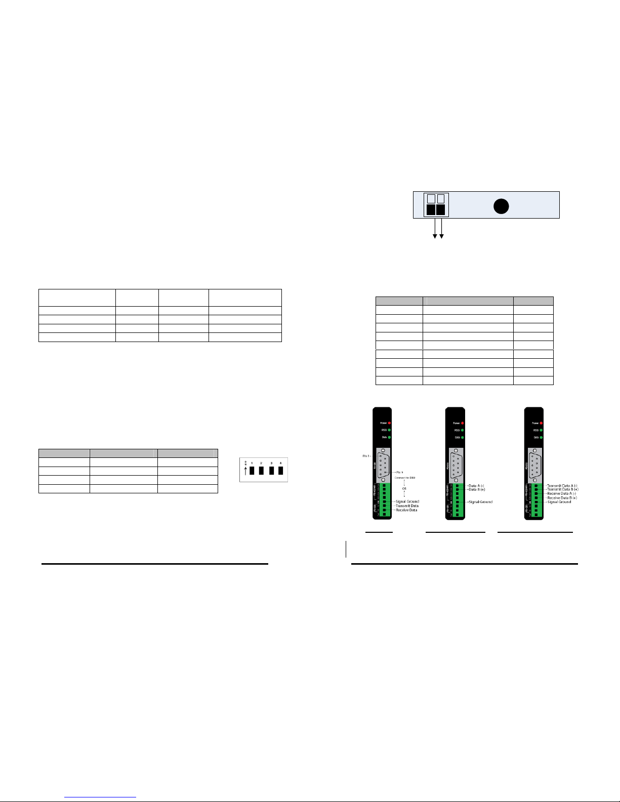
RS-485 (2Wire) RS-422/485 (4Wire) RS-232
Power supply is 10-48 VDC or 18-30 VAC
– +
Determine RS-232, RS-422, RS-485 communication
RS-232 always present on DB9
DB9F Pin Signal Name Direction
1 Data Carrier Detect Out
2 Receive Data Out
3 Transmit Data In
4 Data Terminal Ready In
5 Signal Ground --6 Data Set Ready Out
7 Request To Send In
8 Clear To Send Out
9 Not used ---
10-48 VDC
or
18-30 VAC
Page 3
Manual Documentation Number: MDRxxxxA-807 3
Black Box Corporation - 1000 Park Drive - Lawrence, PA 150 55-1018
www.blackbox.com -- Tech Support and Ordering: 724-746-5500 - Fax: 724-746-0746
Note: The DTR input is used to put the radio into sleep mode. The
radio sleep option must be enabled first using the configuration
software. Once enabled, lowering the DTR signal will put the radio
in sleep mode and raising the DTR signal will put the radio in idle
mode, ready to receive or transmit data.
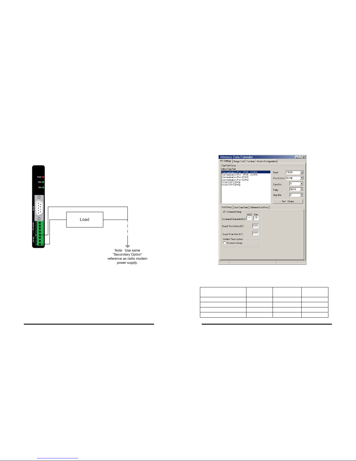
Wireless Link Failure Output
Wireless Data Extenders offer a source
(PNP)transistor output when the wireless signal
strength drops below a critical level (link failure
or miss packets)
40 mA max current
Note: For the RSSI LED to work correctly the “RP” command (RSSI
PWM Timer) must be set to “FF”.
5) Software Installation
Insert CD and it will autostart
Follow screen instructions to install software
Connect to PC with straight through serial cable
4 Manual Documentation Number: MDRxxxxA-807
Black Box Corporation - 1000 Park Drive - Lawrence, PA 150 55-1018
www.blackbox.com -- Tech Support and Ordering: 724-746-5500 - Fax: 724-746-0746
6) Basic Software Configuration
Under PC Settings
Setup your COM port
♦ Baud Rate (Default is…9 60 0 )
♦ Flow Control (Default is…none)
♦ Data Bits (Default is…8)
♦ Parity (Default is…none)
♦ Stop Bits (Default is…1)
Test Connection with Test/Query button
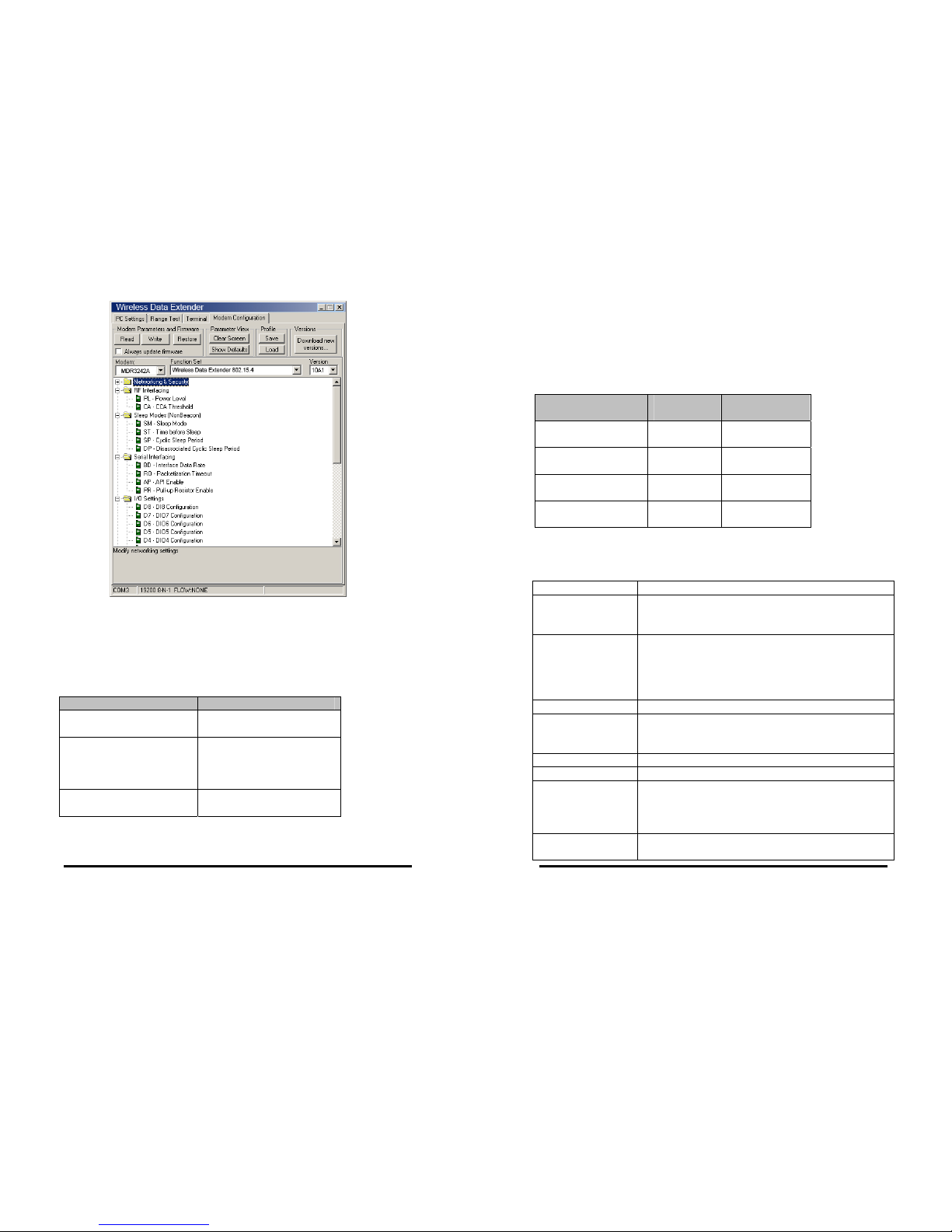
¾ Under Modem Configuration Tab
Select Appropriate Modem Part Number or use the
“Read” button to automatically detect the Modem type.
Follow on-screen help files and refer to section 10 for advanced operations.
Model # Frequency Radio
Power
RF Data
Rate
MDR3242A 2.4GHz 50mW 19.2Kbps
MDR3241A 2.4GHz 50mW 9600bps
MDR3902A 900MHz 100mW 19.2Kbps
MDR3901A 900MHz 100mW 9600bps
Page 4
Manual Documentation Number: MDRxxxxA-807 5
Black Box Corporation - 1000 Park Drive - Lawrence, PA 150 55-1018
www.blackbox.com -- Tech Support and Ordering: 724-746-5500 - Fax: 724-746-0746
7) LED Status
Table 3
Note: For the RSSI LED to work correctly the “RP” command (RSSI
PWM Timer) must be set to “FF”.
Front Panel LED Status
Power Red = ON
OFF = No Power
RSSI (Signal Strength) Green = Strong
Yellow = OK
Red = Weak
OFF = No Signal
Wireless Data Green = Blink ON with
data
6 Manual Documentation Number: MDRxxxxA-807
Black Box Corporation - 1000 Park Drive - Lawrence, PA 150 55-1018
www.blackbox.com -- Tech Support and Ordering: 724-746-5500 - Fax: 724-746-0746
8) Range Selection/Antenna Selection
The Zlinx Product is shipped with an antenna with the
following expected ranges (see table 4)
• These ranges are for reference only with Line of
Sight
• The antenna connector on the Zlinx product is a
reverse polarity SMA female plug
Table 4
9) Table of Specifications
RF Properties
Physical Standard MDR3242A = Propriet ary radio
MDR3241A = Proprietary radio
MDR3902A = Proprietary radio
Range Radio Dependant
MDR324xA (2.4GHz) = up to 600 feet indoor or
3 mile outdoor
MDR390xA (900MHz) = up to 1500 feet indoor
or 7 mile outdoor
Frequency 900MHz/2.4GHz
Transmit Power Radio Dependant
MDR390xA = 100mW (900MHz),
MDR324xA = 50mW (2.4GHz)
Software
Wireless Data Extender
Support Win 98, ME, 2K, XP
Features AT Command
Terminal emulation
RSSI signal range test
Modem emulation
Antenna Options
External Reverse Polarity SMA male jack
connector, omni directional (included with
Model # Indoor
Range
Outdoor
Range
MDR3242A up to 600
feet
up to 3 miles
MDR3241A up to 600
feet
up to 3 miles
MDR3902A up to 1500
feet
up to 7 miles
MDR3901A up to 1500
feet
up to 7 miles
Page 5

Manual Documentation Number: MDRxxxxA-807 7
Black Box Corporation - 1000 Park Drive - Lawrence, PA 150 55-1018
www.blackbox.com -- Tech Support and Ordering: 724-746-5500 - Fax: 724-746-0746
product)
Radio Address
Defaulted at factory, set by software otherwise
Serial settings
Baud 1200, 2400, 4800, 9600, 19200, 38400, 57600
Data bit 7, 8
Parity None, even, odd, mark, space
Stop bit 1, 2
RS-232
Connector DB9F DCE
Lines TX, RX, RTS, CTS, DTR, DSR, DCD, RI, GND
Connector Removable terminal block
Lines TX, RX, GND
RS-422
Connector Removable terminal block
Lines 2 or 4 wire – TX+, TX-, RX+, RX-, GND (2 or 4
wire dipswitch selectable)
Termination 120 Ohm Dipswitch selectable
RS-485
Connector Removable terminal block
Lines 2 or 4 wire with SD control – TX+, TX-, RX+,
RX-, GND (2 or 4 wire dipswitch selectable)
SD control Bit wise
Termination 120 Ohm Dipswitch selectable
Transistor link
failure
No wireless signal or RSSI LED off
Connector Removable terminal block with RS-422/485
Output type Open collector, dry contact, 40mA
Power Supply
Connector Removable terminal block
Input Voltage 10–48VDC, 18-30VAC
Power
Consumption
MDR324xA = 1.5W max
MDR390xA = 1.5W max
Dimensions
1.2W x 3.3D x 4.7H
Environmental
Intended for indoor use only
Operating
Temperature
-40 to 85ºC (-40 to 185ºF)
Storage
Temperature
-40 to 85ºC (-40 to 185ºF)
Operating
Humidity
10 to 90% non-condensing
Enclosure
Rating
Rating IP30
8 Manual Documentation Number: MDRxxxxA-807
Black Box Corporation - 1000 Park Drive - Lawrence, PA 150 55-1018
www.blackbox.com -- Tech Support and Ordering: 724-746-5500 - Fax: 724-746-0746
Mounting DIN rail mount, 35mm
LED Status
Front Panel LED Status
Power Red = On
OFF = No Power
RSSI (Signal
Strength)
Green = Strong
Yellow = OK
Red = Weak
OFF = No Signal
Wireless Data Green = Blink on with
data
Note: For the RSSI LED to work correctly the
“RP” command (RSSI PWM Timer), must be set
to “FF”
Certifications
FCC
FCC Part 15 Class B
CE
CISPR (EN55022) Class B
EN61000-6-1 Generic Standards for Residential,
Commercial, & Light Industrial
EN61000-4-2 ESD
EN61000-4-3 RFI
EN61000-4-4 EFT
EN61000-4-5 Surge
EN61000-4-6 CI
EN61000-4-8 Power Frequency Magnetic
EN61000-4-11 Voltage Dips & Interruptions
RoHS directive
(lead free)
Yes
Page 6

Manual Documentation Number: MDRxxxxA-807 9
Black Box Corporation - 1000 Park Drive - Lawrence, PA 150 55-1018
www.blackbox.com -- Tech Support and Ordering: 724-746-5500 - Fax: 724-746-0746
10) Advanced Programming
For information about entering and exiting AT and Binary Command
Modes, refer to the Command Mode section.
AT Command Example
To Send AT Commands (Using the Terminal tab of Wireless Data Extender
Software)
Example: Both of the following examples change the module’s destination address to
0x1A0D and save the new address to non-volatile memory.
Method 1 (One line per command)
Send AT Command System Response
+++
OK <CR> (Enter into Command Mode)
ATDT <Enter> current Destination Address <CR> (Read)
ATDT1A0D <Enter> OK <CR> (Change destination address)
ATWR <Enter> OK <CR> (Write to non-volatile memory)
ATCN <Enter> OK <CR> (Exit Command Mode)
Method 2 (Multiple commands on one
line)
Send AT Command System Response
+++ OK <CR> (Enter into Command Mode)
ATDT <Enter> current Destination Address <CR> (Read)
ATDT1A0D,WR,CN <Enter> OK <CR> (Execute commands)
Note: In order to use a host PC and the Wireless Data Extender Software
Terminal tab to send data to the module, PC com port s e t t ings must match
the baud, parity & stop bit parameters stored in the module.
Use the “PC Settings” tab to configure P C com por t se t t ing s to mat c h
module parameter values.
10 Manual Documentation Number: MDRxxxxA-807
Black Box Corporation - 1000 Park Drive - Lawrence, PA 150 55-1018
www.blackbox.com -- Tech Support and Ordering: 724-746-5500 - Fax: 724-746-0746
Binary Command Example
To Send Binary Commands:
Note: (pin 1) is de-asserted high when commands are being executed.
Hardware flow control must be disabled as will hold off parameter bytes.
Command Reference Table
Zlinx Commands (The module expects numerical values in hexadecimal.
“d” denotes decimal equivalent.)
AT
Command
Binary
Command
AT
Command
Name
Range
Command
Category
# Bytes
Returned
Factory
Default
AM v4.30* 0x3A (58d) Auto-set MY
-
Networking
& Security
- -
AT 0x05 (5d) Guard Time
After
0x02 –
0xFFF
F [x
100
msec]
Command
Mode
Options
2 0x0A
(10d)
BD v4.2B* 0x15 (21d) Baud Rate
Stand
ard
baud
rates:
0 – 6
(custo
m
rates
also
suppor
ted)
Serial
Interfacing
2
factoryset RF
data rate
Example: Use binary commands to change the Zlinx Module’s destination address to
0x1A0D and save the new address to non-volatile memory.
1. RT Command must be set to “1” in AT Command Mode to enable binary
programming.
2. Assert CMD (Pin 5 is driven high). (Enter Binary Command Mode)
3. Send Bytes (parameter bytes must be 2 bytes long):
00 (Send DT (Destination Address) Command)
0D (Least significant byte of parameter bytes)
1A (Most significant byte of parameter bytes)
08 (Send WR (Write) Command)
4. De-assert CMD (Pin 5 is driven low) (Exit Binary Command Mode)
Page 7

Manual Documentation Number: MDRxxxxA-807 11
Black Box Corporation - 1000 Park Drive - Lawrence, PA 150 55-1018
www.blackbox.com -- Tech Support and Ordering: 724-746-5500 - Fax: 724-746-0746
BK v4.30* 0x2E (46d) Serial Break
Passing
0 – 1 Serial
Interfacing
1 0
BO v4.30* 0x30 (48d) Serial Break
Timeout
0 0xFFF
F [x 1
secon
d]
Serial
Interfacing
2 0
BT 0x04 (4d) Guard Time
Before
0 –
0xFFF
F [x
100
msec]
Command
Mode
Options
2 0x0A
(10d)
CB v4.30* 0x33 (51d) Connection
Duration
Timeout
0x01 –
0xFFF
F [x
100
msec]
Networking
& Security
2 0x28 (4d
sec)
CC 0x13 (19d) Command
Sequence
Character
0x20 –
0x7F
Command
Mode
Options
1 0x2B
(“+”)
CD v4.2B* 0x28 (40d) DO3
Configuration
0 – 4 Serial
Interfacing
1 0
CE v4.30* 0x34 (52d) Connection
Inactivity
Timeout
0 –
0xFFF
F [x 10
msec]
Networking
& Security
2 0x64 (1d
sec)
CF v4.30* 0x35 (53d) Connection
Failure
Count
0 –
0xFFF
F
Networking
& Security
2 0
CL v4.30* 0x39 (57d) Last
Connection
Address
[readonly]
Diagnostics 2
-
CM v4.30* 0 x38 (56d) Connection
Message
0 – 1 Networking
& Security
1 0
CN 0x09 (9d) Exit AT
Command
Mode
-
Command
Mode
Options
- -
CO v4.30* 0x2F (47d) DO3 Timeout 0 -
0xFFF
F [x 1
secon
d]
Serial
Interfacing
2 0x03
CS
v4.27D*
0x1F (31d) DO2
Configuration
0 – 4 Serial
Interfacing
1 0
CT 0x06 (6d) Command
Mode
Timeout
0x02 –
0xFFF
F [x
100
msec]
Command
Mode
Options
2 0xC8
(200d)
DC v4.30* 0x37 (55d) Disconnect
-
Networking
& Security
- -
DR v4.30* 0x2D
(45d)
DI3
Configuration
0 – 4 Serial
Interfacing
1 0
DT 0x00 (0d) Destination
Address
0 –
0xFFF
Networking
& Security
2 0
12 Manual Documentation Number: MDRxxxxA-807
Black Box Corporation - 1000 Park Drive - Lawrence, PA 150 55-1018
www.blackbox.com -- Tech Support and Ordering: 724-746-5500 - Fax: 724-746-0746
F
E0 0x0A (10d) Echo Off
-
Command
Mode
Options
- -
E1 0x0B (11d) Echo On
-
Command
Mode
Options
- -
ER 0x0F (15d) Receive
Error Count
0 –
0xFFF
F
Diagnostics 2 0
FH 0x0D
(13d)
Force Wakeup Initializer
-
Sleep (Low
Power)
- -
FL 0x07 (7d) Software
Flow Control
0 – 1 Serial
Interfacing
1 0
FT
v4.27B*
0x24 (36d) Flow Control
Threshold
0 –
0xFF
[bytes]
Serial
Interfacing
2 varies
GD 0x10 (16d) Receive
Good Count
0 –
0xFFF
F
Diagnostics 2 0
HP 0x11 (17d) Hopping
Channel
0 – 6 Networking
& Security
1 0
HT 0x03 (3d) Time before
Wake-up
Initializer
0 –
0xFFF
F [x
100
msec]
Sleep (Low
Power)
2 0xFFFF
ID v4.2B* 0x27 (39d) Modem VID
Usersettabl
e:
0x10 0x7FF
F
Readonly:
0x800
0 –
0xFFF
F
Networking
& Security
2 -
IU v4.30* 0x3B (59d) DI2, DI3
Update
Timer
0 0xFFF
F [x
100
msec]
Serial
Interfacing
2 0x0A
(10d)
LH 0x0C
(12d)
Wake-up
Initializer
Timer
0 –
0xFF
[x 100
msec]
Sleep (Low
Power)
1 0x01
MD v4.30* 0x32 (50d) RF Mode 0 – 4 Networking
& Security
1 0
MK 0x12 (18d) Address
Mask
0 –
0xFFF
F
Networking
& Security
2 0xFFFF
MY v4.30* 0x2A (42d) Source
Address
0 –
0xFFF
Networking
& Security
2 0xFFFF
Page 8

Manual Documentation Number: MDRxxxxA-807 13
Black Box Corporation - 1000 Park Drive - Lawrence, PA 150 55-1018
www.blackbox.com -- Tech Support and Ordering: 724-746-5500 - Fax: 724-746-0746
F
NB v4.30* 0x23 (35d) Parity 0 – 5 Serial
Interfacing
1 0
PC v4.22* 0x1E (30d) Power-up
Mode
0 – 1 Command
Mode
Options
1 0
PK v4.30* 0x29 (41d) RF Packet
Size
0 0x100
[bytes]
Serial
Interfacing
2 0x40
(64d)
PW v4.22* 0x1D
(29d)
Pin Wake-up 0 – 1 Sleep (Low
Power)
1 0
RB v4.30* 0x20 (32d) Packetization
Threshold
0 0x100
[bytes]
Serial
Interfacing
2 0x01
RE 0x0E (14d) Restore
Defaults
-
(Special)
- -
RN v4.22* 0x19 (25d) Delay Slots 0 –
0xFF
[slots]
Networking
& Security
1 0
RO v4.2A* 0x21 (33d) Packetization
Timeout
0 –
0xFFF
F [x
200
µsec]
Serial
Interfacing
2 0
RP v4.2A* 0x22 (34d) RSSI PWM
Timer
0 0x7F
[x 100
msec]
Diagnostics 1 0
RR v4.22* 0x18 (24d) Retries 0 –
0xFF
Networking
& Security
1 0
RS v4.22* 0x1C
(28d)
RSSI 0x06 –
0x36
[readonly]
Diagnostics 1
-
RT 0x16 (22d) DI2
Configuration
0 - 2 Serial
Interfacing
1 0
RZ v4.30* 0x2C
(44d)
DI Buffer
Size
[readonly]
Diagnostics
- -
SB v4.2B* 0x36 (54d) Stop Bits 0 - 1 Serial
Interfacing
1 0
SH
v4.27C*
0x25 (37d) Serial
Number High
0 –
0xFFF
F
[readonly]
Diagnostics 2
-
SL
v4.27C*
0x26 (38d) Serial
Number Low
0 –
0xFFF
F
[readonly]
Diagnostics 2
-
SM 0x01 (1d) Sleep Mode 0 – 8 Sleep (Low
Power)
1 0
ST 0x02 (2d) Time before
Sleep
0x10 –
0xFFF
F [x
Sleep (Low
Power)
2 0x64
(100d)
14 Manual Documentation Number: MDRxxxxA-807
Black Box Corporation - 1000 Park Drive - Lawrence, PA 150 55-1018
www.blackbox.com -- Tech Support and Ordering: 724-746-5500 - Fax: 724-746-0746
100
msec]
SY 0x17 (23d) Time before
Initialization
0 –
0xFF
[x 100
msec]
Networking
& Security
1 0
(disabled
)
TO v4.30* 0x31 (49d) DO2 Timeout 0 -
0xFFF
F (x 1
sec)
Serial
Interfacing
2 0x03
TR v4.22* 0x1B (27d) Transmit
Error Count
0 –
0xFFF
F
Diagnostics 2 0
TT v4.22* 0x1A (26d) Streaming
Limit
0 –
0xFFF
F [0 =
disabl
ed]
Networking
& Security
2 0xFFFF
VR 0x14 (20d) Firmware
Version
0 x
0xFFF
F
[readonly]
Diagnostics 2
-
WR 0x08 (8d) Write
-
(Special)
- -
*Firmware version in which command and parameter options were first supported.
Zlinx Command Descriptions
Command descriptions in this section are listed alphabetically. Command categories
are designated within “< >” symbols that follow each command title. Zlinx Modules
expect parameter numerical values in hexadecimal (designated by the “0x” prefix).
AM (Auto-set MY) Command
<Networking & Security> AM
Command is used to
automatically set the MY
(Source Address) parameter from the factory-set module serial number. The address
is formed with bits 29, 28 and 13-0 of the serial number (in that order).
AT (Guard Time After)
Command
<Command Mode Options> AT
Command is used to set the DI
time-of-silence that follows the
AT command sequence
character (CC Command).
By default, AT Command Mode
will activate after one second of
silence.
NOTE: AT Commands issued without a parameter value will return the currently
stored parameter.
AT Command: ATAM
Binary Command: 0x3A (58 decimal)
Minimum firmware version required: 4.40
Binary Command: 0x05 (5 decimal)
Parameter
Range:
0x02 – 0xFFFF [x 100
milliseconds]
Number of bytes returned: 2
Default Parameter Value: 0x0A (10
decimal)
Related Commands: BT (Guard Time
Before), CC (Command Sequence
Character)
Page 9

Manual Documentation Number: MDRxxxxA-807 15
Black Box Corporation - 1000 Park Drive - Lawrence, PA 150 55-1018
www.blackbox.com -- Tech Support and Ordering: 724-746-5500 - Fax: 724-746-0746
Refer to the AT Commands section to view the default AT Command Mode
Sequence.
BD (Interface Data Rate)
Command
<Serial Interfacing> BD
Command allows the user to
adjust the UART interface data
rate and thus modify the rate at
which serial data is sent to the RF
module. The new baud rate does
not take effect until the CN
command is issued. The RF data
rate is unaffected by the BD
parameter.
Most applications will require one
of the seven standard baud rates;
however, non-standard baud
rates are also supported.
Note: If the interface data rate is
set to exceed the fixed RF data
rate of the module, flow control
may need to be implemented as
described in the Pin, Flow Control
and CS (DO2 Configuration)
sections.
Non-standard Interface Data Rates: When parameter values outside the range of
standard interface data rates are sent, the closest rate represented by the number is
stored in the BD register. For example, a rate of 19200 bps can be set by sending the
following command line "ATBD4B00". NOTE: When using BLACK BOX’s Zlinx
Software, non-standard interface data rates can only be set and read using the Zlinx
‘Terminal’ tab.
When the BD command is sent with a non-standard interface data rate, the UART will
adjust to accommodate the requested interface rate. In most cases, the clock
resolution will cause the stored BD parameter to vary from the parameter that was
sent (refer to the table below). Reading the BD command (send "ATBD" command
without an associated parameter value) will return the value that was actually stored
in the BD register.
Parameter Sent vs. Parameter Stored BD Parameter Sent (HEX) Interface Data
Rate (bps)
BD Parameter
Sent (HEX)
Interface Data Rate (bps)
BD Parameter
Stored (HEX)
0 1200 0
4 19,200 4
7 115,200 7
12C 300 12B
1C200 115,200 1B207
AT Command: ATBD
Binary Command: 0x15 (21 decimal)
Parameter Range (Standard baud rates): 0 – 6
(Non-standard baud rates): 0x7D – 0xFFFF
Parameter Configuration (bps)
0 1200
1 2400
2 4800
3 9600
4 19200
5 38400
6 57600
Number of bytes returned: 2
Default Parameter Value: Set to equal module’s
factory-set RF data rate.
Related Commands: CN (Exit Command Mode)
Minimum firmware version required: 4.2B
(Custom baud rates not previously supported.)
16 Manual Documentation Number: MDRxxxxA-807
Black Box Corporation - 1000 Park Drive - Lawrence, PA 150 55-1018
www.blackbox.com -- Tech Support and Ordering: 724-746-5500 - Fax: 724-746-0746
BK (Serial Break Passing)
Command
<Serial Interfacing> Pass a serial
break condition on t he DI pin to
the DO pin of another module.
BO (Serial Break Timeout)
Command
<Serial Interfacing> DO pin will
return to default after no serial
break status information is
received during the timeout
period.
Use with BK parameter = 1.
BT (Guard Time Before)
Command
<Command Mode Options> BT
Command is used to set the DI
pin silence time that must
precede the command sequence
character (CC Command) of the
AT Command Mode Sequence.
Refer to the AT Commands
section to view the default AT
Command Mode sequence.
AT Command: ATBK
Binary Command: 0x2E (46 decimal)
Parameter Range: 0 – 1
Parameter Configuration
0 disable
1 enable
Default Parameter Value: 0
Number of bytes returned: 1
Related Commands: BO (Serial Break Timeout)
Minimum Firmware Version Required: 4.30
AT Command: ATBO
Binary Command: 0x30 (48 decimal)
Parameter Range:
0 – 0xFFFF
[x 1 second]
Default Parameter Value: 0
Number of bytes returned: 2
Related Commands: BK (Serial Break Passing)
Minimum Firmware Version Required: 4.30
AT Command: ATBT
Binary Command: 0x04 (4 decimal)
Parameter Range: 0 – 0xFFFF
[x 100 milliseconds]
Default Parameter Value: 0x0A (10 decimal)
Number of bytes returned: 2
Related Commands: AT (Guard Time After), CC
(Command Sequence Character)
Page 10

Manual Documentation Number: MDRxxxxA-807 17
Black Box Corporation - 1000 Park Drive - Lawrence, PA 150 55-1018
www.blackbox.com -- Tech Support and Ordering: 724-746-5500 - Fax: 724-746-0746
CB (Connection Durat ion
Timeout) Command
<Networking & Security>
Set/Read the maximum amount
of time an exclusive
connection between a base and
remote module in a point-tomultipoint network is sustained.
The remote module will
disconnect when this timeout
expires.
CC (Command Sequence
Character) Command
<Command Mode Options> CC
Command is used to set the
ASCII character to be used
between Guard Times of the AT
Command Mode Sequence
(BT+ CC + AT). The AT
Command Mode Sequence
activates AT Command Mode
(from Idle Mode).
Refer to the AT Commands section to view the default AT Command Mode
sequence.
CD (DO3 Configuration)
Command
<Serial Interfacing> CD
Command is used to redefine the
behavior of the DO3 (Data Output
3)/RX LED line.
CE (Connection Inactivity Timeout) Command
Binary Command: 0x33 (51 decimal)
Parameter Range: 0x01 – 0xFFFF
[x 100 milliseconds]
Default Parameter Value: 0x28 (4d seconds)
Number of bytes returned: 2
Related Commands: CE (Connection Inactivity
Timeout), DC (Disconnect), MD (RF Mode)
Minimum Firmware Version Required: 4.30
AT Command: ATCC
Binary Command: 0x13 (19 decimal)
Parameter Range: 0x20 – 0x7F
Default Parameter Value: 0x2B (ASCII “+” sign)
Number of bytes returned: 1
Related Commands: AT (Guard Time After), BT
(Guard Time Before)
AT Command: ATCD
Binary Command: 0x28 (40 decimal)
Parameter Range: 0 – 4
Parameter Configuration
0 RX LED
1 Default high
2 Default low
3 (reserved)
4
Assert only when packet
addressed to module sent
Default Parameter Value: 0
Number of bytes returned: 1
Minimum Firmware Version Required: 4.2B
18 Manual Documentation Number: MDRxxxxA-807
Black Box Corporation - 1000 Park Drive - Lawrence, PA 150 55-1018
www.blackbox.com -- Tech Support and Ordering: 724-746-5500 - Fax: 724-746-0746
<Networking & Security>
Set/Read the duration of
inactivity that will cause a break
in a connection between
modules. The base module
will disconnect when no payload
has been transferred for the time
specified by the CE parameter.
CF (Connection Failure Count)
Command
<Diagnostics> Set/Read the
number of times the base module
expired retries attempting to send
a Connection Grant Packet. Set
to zero to clear the register.
CL (Last Connection Address)
Command
<Diagnostics/Networking &
Security> Read the address of
the remote module that last
connected to the base module. A
remote module will return its DT
(Destination Address) parameter.
CM (Connection Message)
Command
<Networking & Security> Select
whether base sends connect
messages to the host when a
connection is established. When
enabled, a “CONNECTXXXX”
string is sent to the host of the
base module. “XXXX” is the MY
(Source Address) of the
connected remote module.
CN (Exit AT Command Mode)
Command
<Command Mode Options> CN
Command is used to explicitly exit AT Command Mode.
AT Command: ATCE
Binary Command: 0x34 (52 decimal)
Parameter Range: 0 – 0xFFFF
[x 10 milliseconds]
Default Parameter Value: 0x64 (1d second)
Number of bytes returned: 2
Related Commands: CB ( Conn e c t i on Dur a ti o n
Timeout), DC (Disconnect), MD (RF Mode)
Minimum Firmware Version Required: 4.30
AT Command: ATCF
Binary Command: 0x35 (53 decimal)
Parameter Range: 0 – 0xFFFF
Default Parameter Value: 0
Number of bytes returned: 2
Minimum Firmware Version Required: 4.30
AT Command: ATCL
Binary Command: 0x39 (57 decimal)
Parameter Range: 0 – 0xFFFF [read-only]
Number of bytes returned: 2
Minimum Firmware Version Required: 4.30
AT Command: ATCM
Binary Command: 0x38 (56 decimal)
Parameter Range: 0 – 1
Parameter Configuration
0 enable
1 disable
Default Parameter Value: 0
Number of bytes returned: 1
Minimum Firmware Version Required: 4.30
AT Command: ATCN
Binary Command: 0x09 (9 decimal)
Page 11

Manual Documentation Number: MDRxxxxA-807 19
Black Box Corporation - 1000 Park Drive - Lawrence, PA 150 55-1018
www.blackbox.com -- Tech Support and Ordering: 724-746-5500 - Fax: 724-746-0746
CO (DO3 Timeout) Command
<Serial Interfacing> DO3 (Data
Output 3) output will return to
default after no DI3 (Data Input
3) status information is received
during the timeout period.
Use with CD = 1 or 2, DR = 1.
CS (DO2 Configuration)
Command
<Serial Interfacing> CS
Command is used to select the
behavior of the DO2 (Data
Output 2) pin signal. This output
can provide RS-232 flow
control, control the TX enable
signal (for RS-485 or RS-422
operations), or set the default
level for the I/O line passing
function.
By default, DO2 provides RS232 (Clear-to- Send) flow
control.
AT Command: ATCO
Binary Command: 0x2F (47 decimal)
Parameter Range: 0 – 0xFFFF [x 1 second]
Default Parameter Value: 3
Number of bytes returned: 2
Related Commands: CD (DO3
Configuration),DR (DI3 Configuration)
Minimum Firmware Version Required: 4.30
AT Command: ATCS
Binary Command: 0x1F (31 decimal)
Parameter Range: 0 – 4
Parameter Configuration
0 RS-232 flow control
1 RS-485 TX enable low
2 high
3 RS-485 TX enable high
4 low
Default Parameter Value: 0
Number of bytes returned: 1
Related Commands: RT (DI2 Configuration), TO
(DO2 Timeout)
Minimum Firmware Version Required: 4.27D
20 Manual Documentation Number: MDRxxxxA-807
Black Box Corporation - 1000 Park Drive - Lawrence, PA 150 55-1018
www.blackbox.com -- Tech Support and Ordering: 724-746-5500 - Fax: 724-746-0746
CT (Command Mode Timeout)
Command
<Command Mode Options> CT
Command is used to set the
amount of time of inactivity
before AT Command Mode
automatically terminates. After a
CT time of inactivity, the module
exits AT Command Mode and
returns to Idle Mode. AT
Command Mode can also be exited manually using the CN (Exit AT Command Mode)
Command.
DC (Disconnect) Command
<Networking & Security> DC
Command is used (when in
Multi-Streaming Mode (MD = 1
or 2)) to explicitly force the
disconnection of an active
exclusive connection. If MD = 1,
the base module will force the
disconnection of an exclusive connection. If MD = 2, the remote module will send a
“Disconnect Request Packet” to the base module
DR (DI3 Configuration)
Command
<Serial Interfacing> DR
Command is used to configure
DI3 (pin 2, SLEEP) for I/O line
passing (use with CD = 1 or 2
and CO) or controlling
connection status (use with MD
= 1 or 2).
AT Command: ATCT
Binary Command: 0x06 (6 decimal)
Parameter Range: 2 – 0xFFFF
[x 100 milliseconds]
Default Parameter Value: 0xC8 (200 decimal, 20
seconds)
Number of bytes returned: 2
AT Command: ATDC
Binary Command: 0x37 (55 decimal)
Related Commands: CB (Connection Duration
Timeout), CE (Connection Inactivity Timeout),
MD (RF Mode)
Minimum Firmware Version Required: 4.30
AT Command: ATDR
Binary Command: 0x2D (45 decimal)
Parameter
Range:
0 – 4
Parameter Configuration
0 Disabled
1 DI3 I/O passing enabled
2 Connect on low
3 Disconnect on high
4 Connect and Disconnect
Default Parameter Value: 0
Number of bytes returned: 1
Related Commands: CD (DO3 Configuration),CO
(DO3 Timeout), MD (RF Mode)
Minimum Firmware Version Required: 4.30
Page 12

Manual Documentation Number: MDRxxxxA-807 21
Black Box Corporation - 1000 Park Drive - Lawrence, PA 150 55-1018
www.blackbox.com -- Tech Support and Ordering: 724-746-5500 - Fax: 724-746-0746
DT (Destination Address)
Command
<Networking & Security> DT
Command is used to set the
networking address of an Zlinx
Module. Zlinx Modules use three
filtration layers: Channels
(ATHP), Vendor Identification
Number (ATID) and Destination
Addresses (ATDT). DT
Command assigns an address to a module that enables it to communicate only with
other modules having the same addresses. All modules that share the same
Destination Address can communicate freely with each other. Modules in the same
network with a different Destination Address (than that of the transmitter) will listen to
all transmissions to stay synchronized, but will not send any of the data out their serial
ports.
E0 (Echo Off) Command
<Command Mode Options> The
E0 command turns off character
echo in AT Command Mode.
By default, echo is off.
E1 (Echo On) Command
<Command Mode Options> E1
Command turns on the echo in
AT Command Mode. Each
typed character will be echoed back to the terminal when ATE1 is active. E0 is the
default.
ER (Receive Error Count)
Command
<Diagnostics> Set/Read the
receive error count. The errorcount records the number of
packets partially received then
aborted on reception error. This
value returns to 0 after a reset
and is not non-volatile (value
does not persist in the module’s
memory after a power-up sequence). Once the receive error count reaches its
maximum value (up to 0xFFFF), it remains at its maximum count value until the
maximum count value is explicitly changed or the module is reset.
AT Command: ATDT
Binary Command: 0x00
Parameter Range: 0 – 0xFFFF
Default Parameter Value: 0
Number of bytes returned: 2
Related Commands: HP (Hopping Channel), ID
(Module VID), MK (Address Mask)
AT Command: ATE0
Binary Command: 0x0A (10 decimal)
AT Command: ATE1
Binary Command: 0x0B (11 decimal)
AT Command: ATER
Binary Command: 0x0F (15 decimal)
Parameter Range: 0 – 0xFFFF
Default Parameter Value: 0
Number of bytes returned: 2
Related Commands: GD (Receive Good Count)
22 Manual Documentation Number: MDRxxxxA-807
Black Box Corporation - 1000 Park Drive - Lawrence, PA 150 55-1018
www.blackbox.com -- Tech Support and Ordering: 724-746-5500 - Fax: 724-746-0746
FH (Force Wake-up Initializer)
Command
<Sleep (Low Power)> FH
Command is used to force a Wake-up Initializer to be sent on the next transmission.
WR (Write) Command does not need to be issued with FH Command.
Use only with cyclic sleep modes active on remote modules.
FL (Software Flow Cont rol)
Command
<Serial Interfacing> FL
Command is used to configure
of module with software flow
control. Hardware flow control
is implemented with the Zlinx
Module as the DO2 pin ( ),
which regulates when serial
data can be transferred to the
module. FL Command is used to
allow software flow control. XON
character used is 0x11 (17
decimal). XOFF character used
is 0x13 (19 decimal).
FT (Flow Control Threshold)
Command
<Serial Interfacing> Set/Read
the flow control threshold. When
FT bytes have accumulated in
the DI buffer, is de-asserted or
the XOFF software flow control
character is transmitted.
AT Command: ATFH
Binary Command: 0x0D (13 decimal)
AT Command: ATFL
Binary Command: 0x07 (7 decimal)
Parameter Range: 0 – 1
Parameter Configuration
0
Disable software flow
control
1
Enable software flow
control
Default Parameter Value: 0
Number of bytes returned: 1
AT Command: ATFT
Binary Command: 0x24 (36 decimal)
Parameter Range: 0 – 0xFF [bytes] (Maximum
value equals the receiving module DO buffer
size minus 0x11 bytes)
Default Parameter Value: Receiving module DO
Buffer size minus 0x11
Number of bytes returned: 2
Minimum Firmware Version Required: 4.27B
Page 13

Manual Documentation Number: MDRxxxxA-807 23
Black Box Corporation - 1000 Park Drive - Lawrence, PA 150 55-1018
www.blackbox.com -- Tech Support and Ordering: 724-746-5500 - Fax: 724-746-0746
GD (Receive Good Count)
Command
<Diagnostics> Set/Read the
count of good received RF
packets. Parameter value is
reset to 0 after every reset and
is not non-volatile (value does
not persist in the module’s
memory after a power-up
sequence). Once the “Receive
Good Count” reaches its maximum value (up to 0xFFFF), it remains at its maximum
count value until the maximum count value is manually changed or the module is
reset.
HP (Hopping Channel)
Command
<Networking & Security> HP
Command is used to set the
module hopping channel
number. A channel is one of
three layers of addressing
available to the module. In order
for modules to communicate
with each other, the modules
must have the same channel number since each network uses a different hopping
sequence. Different channels can be used to prevent modules in one network from
listening to transmissions of another.
HT (Time before Wake-up
Initializer) Command
<Sleep (Low Power)> If any
modules within range are
running in a “Cyclic Sleep”
setting, a wake-up initializer
must be used by the
transmitting module for sleeping
modules to remain awake [refer
to the LH (“Wake-up Initializer
Timer”) Command]. When a
receiving module in Cyclic Sleep
wakes, it must detect the
wake-up initializer in order to remain awake and receive data. The value of HT
Parameter tells the transmitter, “After a period of inactivity (no transmitting or
receiving) lasting HT amount of time, send a long wake-up initializer”. HT
Parameter should be set to match the inactivity timeout [specified by ST (Time before
Sleep) Command] used by the receiver(s).
From the receiving module perspective, after HT time elapses and the inactivity
timeout (ST command) is met, the receiver goes into cyclic sleep. In cyclic sleep, the
receiver wakes once per sleep interval to check for a wake-up initializer. When a
wake-up initializer is detected, the module will stay awake to receive data. The wakeup initializer must be longer than the cyclic sleep interval to ensure that sleeping
modules detect incoming data. When HT time elapses, the transmitter then knows
AT Command: ATGD
Binary Command: 0x10 (16 decimal)
Parameter Range: 0 – 0xFFFF
Default Parameter Value: 0
Number of bytes returned: 2
Related Commands: ER (Receive Error Count)
AT Command: ATHP
Binary Command: 0x11 (17 decimal)
Parameter Range: 0 – 6
Default Parameter Value: 0
Number of bytes returned: 1
Related Commands: DT (Destination Address),
ID (Module VID), MK (Address Mask)
AT Command: ATHT
Binary Command: 0x03 (3 decimal)
Parameter Range: 0 – 0xFFFF
[x 100 milliseconds]
Default Parameter Value: 0xFFFF (means that
long wake-up initializer will not be sent)
Number of bytes returned: 2
Related Commands: LH (Wake-up Initializer
Timer), SM (Sleep Mode), ST (Time before
Sleep)
24 Manual Documentation Number: MDRxxxxA-807
Black Box Corporation - 1000 Park Drive - Lawrence, PA 150 55-1018
www.blackbox.com -- Tech Support and Ordering: 724-746-5500 - Fax: 724-746-0746
that it needs to send a long Wake-up Initializer for all receivers to be able to remain
awake and receive the next transmission. Matching HT to the time specified by ST on
the receiving module guarantees that all receivers will detect the next transmission.
ID (Modem VID) Command
<Networking & Security>
Set/Read the VID (Vendor
Identification Number). Only
modules with matching VIDs
can communicate with each
other. Modules with nonmatching VIDs will not receive
unintended data transmission.
IU (DI2, DI3 Update Timer)
Command
<Serial Interfacing> Set/Read
the interval at which the status
of DI2, DI3 and Break is
transmitted. Additionally, status
is transmitted whenever there is
a transition. A setting of “0”
disables periodic update. DI2 or
DI3 passing must be enabled
for the update to take place.
LH (Wake-up Initializer Timer) Command
AT Command: ATID
Binary Command: 0x27 (39 decimal)
Parameter Range (user-settable):
0x10 - 0x7FFFF
(Factory-set and read-only):
0x8000 – 0xFFFF
Number of bytes returned: 2
Minimum Firmware Version Required: 4.2B
(previous firmware versions did not support usersettable IDs.)
AT Command: ATIU
Binary Command: 0x3B (59 decimal)
Parameter Range: 0 - 0xFFFF [x 100 ms]
Default Parameter Value: 0x0A (10 decimal)
Number of bytes returned: 2
Related Commands: BK (Serial Break Passing),
BO (Serial Break Timeout), CO (DO3 Timeout),
DR (Disconnect), RT (DI2 Configuration), TO
(DO2 Timeout)
Minimum Firmware Version Required: 4.30
Page 14

Manual Documentation Number: MDRxxxxA-807 25
Black Box Corporation - 1000 Park Drive - Lawrence, PA 150 55-1018
www.blackbox.com -- Tech Support and Ordering: 724-746-5500 - Fax: 724-746-0746
<Sleep (Low Power)> Set/Read
the amount of time during which
the RF initializer is sent. When
receiving modules are put into
Cyclic Sleep Mode, they powerdown after a period of inactivity
[specified by ST (Time before
Sleep) Command] and will
periodically awaken and listen
for transmitted data. In order for
the receiving modules to remain
awake, they must detect ~35ms
of the wake-up initializer.
LH Command must be used whenever a receiver is operating in Cyclic Sleep Mode.
This lengthens the Wake-up Initializer to a specific amount of time (in tenths of a
second). The Wake-up Initializer Time must be longer than the cyclic sleep time that
is determined by SM (Sleep Mode) Command. If the wake-up initializer time were less
than the Cyclic Sleep interval, the connection would be at risk of missing the wake-up
initializer transmission.
MD (RF Mode) Command
<Networking & Security> The
MD command is used to
select/read the RF Mode (Peerto-peer, Multi-Stream or
Repeater Modes) of the
module.
Multi-Streaming Mode enables
exclusive connections in pointto-multipoint networks. Refer to
the Multi-Streaming Mode
section for more information
regarding how these parameter
values affect other parameter
values.
Repeater Mode enables longer
range via an intermediary
module. When MD=3, the
module will act as a “store and
forward” repeater. Any packets
not addressed to this node will
be repeated. A Repeater End Node (MD=4) handles repeated messages, but will not
forward the data over-the-air.
AT Command: ATLH
Binary Command: 0x0C (12 decimal)
Parameter Range: 0 – 0xFF
[x 100 milliseconds]
Default Parameter Value: 1
Number of bytes returned: 1
Related Commands: HT (Time before Wake-up
Initializer), SM (Sleep Mode), ST (Time before
Sleep)
Refer to the figures in the Sleep Mode sections to view correct and
incorrect configuration diagra ms . Th e images help visualize the importance
that the LH value be greater than the SM cyclic sleep value.
AT Command: ATMD
Binary Command: 0x32 (50 decimal)
Parameter Range: 0 – 4
Parameter Configuration
0
Peer-to-Peer (transparent
operation)
1 Multi-Stream Base
2 Multi-Stream Remote
3 Repeater & End Node
4 End Node
Default Parameter Value: 0
Number of bytes returned: 1
Related Commands: CB (Connection Duration
Timeout), CE (Connection Inactivity Timeout),
CM (Connection Message), DC (Disconnect)
Minimum Firmware Version Required: 4.30
26 Manual Documentation Number: MDRxxxxA-807
Black Box Corporation - 1000 Park Drive - Lawrence, PA 150 55-1018
www.blackbox.com -- Tech Support and Ordering: 724-746-5500 - Fax: 724-746-0746
MK (Address Mask) Command
<Networking & Security> MK
Command is used to set/read
the address mask of the
module.
All data packets contain the
destination address (DT
Parameter) of the transmitting
module. When an RF data
packet is received, the
transmitter’s destination address
is logically “ANDed” (bitwise)
with the Address Mask of the
receiver. The resulting value must match the destination address or the address mask
of the receiver for the packet to be received and sent out the module DO serial port. If
the “ANDed”
value does not match either the destination address or the address mask of the
receiver, the packet is discarded. (All “0” values are treated as “irrelevant” values and
are ignored.)
MY (Source Address)
Command
<Networking & Security>
Set/Read the source address of
the module.
AT Command: ATMK
Binary Command: 0x12 (18 decimal)
Parameter Range: 0 – 0xFFFF
Default Parameter Value: 0xFFFF
(Destination address (DT parameter) of the
transmitting module must exactly match the
destination address of the receiving module.)
Number of bytes returned: 2
Related Commands: DT (Destination Address),
HP (Hopping Channel), ID (Module VID), MY
(Source Address)
AT Command: ATMY
Binary Command: 0x2A (42 decimal)
Parameter Range: 0 – 0xFFFF
Default Parameter Value: 0xFFFF (Disabled –
the DT (Destination Address) parameter serves
as both source and destination address.)
Number of bytes returned: 2
Related Commands: DT (Destination Address),
HP (Hopping Channel), ID (Modem VID), MK
(Address Mask), AM (Auto-set MY)
Minimum Firmware Version Required: 4.30
Page 15

Manual Documentation Number: MDRxxxxA-807 27
Black Box Corporation - 1000 Park Drive - Lawrence, PA 150 55-1018
www.blackbox.com -- Tech Support and Ordering: 724-746-5500 - Fax: 724-746-0746
NB (Parity) Command
<Serial Interfacing>
Select/Read parity settings
for UART communications.
PC (Power-up Mode)
Command
<Command Mode Options>
PC Command allows the
module to power-up directly
into AT Command Mode from
reset or power-on. If PC
Command is enabled with SM
Parameter set to 1, DI3 (pin 2)
can be used to enter the
module into AT Command
Mode. When the DI3 pin is
deasserted (low), the module
will wake-up in AT Command
Mode. This behavior allows module DTR emulation.
PK (RF Packet Size)
Command
<Serial Interfacing> Set/Read
the maximum size of the RF
packets sent out a transmitting
module. The maximum packet
size can be used along with
the RB and RO parameters to
implicitly set the channel dwell
time.
Changes to this parameter
may have a secondary effect on the RB (Packet Control Characters) parameter. RB
must always be less than or equal to PK. If PK is changed to a value less than the
current value of RB, RB is automatically lowered to be equal to PK.
AT Command: ATNB
Binary Command: 0x23 (35 decimal)
Parameter Range: 0 – 5
Parameter Configuration
0
8-bit (no parity or 7-bit (any
parity)
1 8-bit even
2 8-bit odd
3 8-bit mark
4 8-bit space
5 9-bit
Default Parameter Value: 0
Number of bytes returned: 1
Minimum Firmware Version Required: 4.30
(previous versions did not support the 9
thbit.
AT Command: ATPC
Binary Command: 0x1E (30 decimal)
Parameter Range: 0 – 1
Parameter Configuration
0 Power-up to Idle Mode
1
Power-up to AT Command
Mode
Default Parameter Value: 0
Number of bytes returned: 1
Minimum Firmware Version Required: 4.22
AT Command: ATPK
Binary Command: 0x29 (41 decimal)
Parameter Range: 0 – 0x100 [Bytes]
Default Parameter Value: 0x40 (64 decimal)
Number of bytes returned: 2
Related Commands: RB (Packetization
Threshold), RO (Packetization Timeout)
Minimum Firmware Version Required: 4.30
28 Manual Documentation Number: MDRxxxxA-807
Black Box Corporation - 1000 Park Drive - Lawrence, PA 150 55-1018
www.blackbox.com -- Tech Support and Ordering: 724-746-5500 - Fax: 724-746-0746
PW (Pin Wake-up) Command
<Sleep (Low Power)> Under
normal operation, a module in
Cyclic Sleep Mode cycles from
an active state to a low-power
state at regular intervals until
data is ready to be received. If
the PW Parameter is set to 1,
SLEEP (pin 2) can be used to
wake the module from Cyclic
Sleep. If the SLEEP pin is deasserted (low), the module will
be fully operational and will not
go into Cyclic Sleep. Once
SLEEP is asserted, the
module will remain active for
the period of time specified by
ST (Time before Sleep) Command and will return to Cyclic Sleep Mode (if no data is
ready to be transmitted). PW Command is only valid if Cyclic Sleep has been
enabled.
RB (Packetization
Threshold) Command
<Serial Interfacing> RF
transmission will commence
when data is in the DI Buffer
and either of the following
criteria are met:
• RO times out on the UART
receive lines
(ignored if RO = 0)
• RB characters have been
received by the UART
(ignored if RB = 0)
If PK is lowered below the value of RB; RB is automatically lowered to match PK.
Note: RB and RO criteria only apply to the first packet of a multi-packet transmission.
If data remains in the DI Buffer after the first packet, transmissions will continue in
streaming manner until there is no data left in the DI Buffer (UART receive buffer).
RE (Restore Defaults)
Command
<Diagnostics> RE Command
restores all configurable parameters to factory default settings. However, RE
Command will not write the restored values to non-volatile (persistent) memory. Issue
the WR (Write) Command after the RE command to save restored parameter values
to non-volatile memory.
AT Command: ATPW
Binary Command: 0x1D (29 decimal)
Parameter Range: 0 – 1
Parameter Configuration
0 Disabled
1 Enabled
Default Parameter Value: 0
Number of bytes returned: 1
Related Commands: SM (Sleep Mode), ST (Time
before Sleep)
Minimum Firmware Version Required: 4.22
AT Command: ATRB
Binary Command: 0x20 (32 decimal)
Parameter Range: 0 – 0x100 [bytes](Maximum
value equals the current value of PK Parameter
(up to 0x100 HEX (800 decimal))
Default Parameter Value: 1
Number of bytes returned: 2
Related Commands: PK (RF Packet Size), RO
(Packetization Timeout)
Minimum Firmware Version Required: 4.30
AT Command: ATRE
Binary Command: 0x0E (14 decimal)
Page 16

Manual Documentation Number: MDRxxxxA-807 29
Black Box Corporation - 1000 Park Drive - Lawrence, PA 150 55-1018
www.blackbox.com -- Tech Support and Ordering: 724-746-5500 - Fax: 724-746-0746
RN (Delay Slots) Command
<Networking & Security> RN
Command is only applicable if
retries have been enabled [RR
(Retries) parameter > 0], or if
forced delays will be inserted
into a transmission [TT
(Streaming Limit) parameter >
0]. RN Command is used to
adjust the time delay that the
transmitter inserts before
attempting to resend a packet.
If the transmitter fails to receive an acknowledgement after sending a packet, it will
insert a random number of delay slots (ranging from 0 to (RN minus 1)) before
attempting to resend the packet. Each delay slot lasts for a period of 38ms.
If two modules attempted to transmit at the same time, the random time delay after
packet failure would allow one of the two modules to transmit the packet successfully,
while the other would wait until the channel opens up to begin transmission.
RO (Packetization Timeout)
Command
<Serial Interfacing> Set/Read
the time of silence (no bytes
received) after which
transmission begins. After a
serial byte is received and if no
other byte is received before
the RO timeout, the
transmission will start.
RP (RSSI PWM Timer)
Command
<Diagnostics> RP Command
is used to enable PWM (Pulse
Width Modulation) output on
the CONFIG pin. The output is
calibrated to show the level the
received RF signal is above
the sensitivity level of the
module. The PWM pulses
vary from zero to 95 percent.
Zero percent means the received RF signal is at or below the published sensitivity
level of the module. The following table shows levels above sensitivity and PWM
values.
The total period of the PWM output is 8.32 ms. Because there are 40 steps in the
PWM output; the minimum step size is 0.208 ms.
AT Command: ATRN
Binary Command: 0x19 (25 decimal)
Parameter Range: 0 – 0xFF [slots]
Default Parameter Value: 0
(no delay slots are inserted)
Number of bytes returned: 1
Related Commands: RR (Retries), TT (Streaming
Limit)
Minimum Firmware Version Required: 4.22
AT Command: ATRO
Binary Command: 0x21 (33 decimal)
Parameter Range: 0 – 0xFFFF [x 200 µs]
Default Parameter Value: 0
Number of bytes returned: 2
Minimum Firmware Version Required: 4.2A
AT Command: ATRP
Binary Command: 0x22 (34 decimal)
Parameter
Range:
0 - 0x7F [x 100 milliseconds]
Default Parameter Value: 0 (disabled)
Number of bytes returned: 1
Minimum Firmware Version Required: 4.2A
30 Manual Documentation Number: MDRxxxxA-807
Black Box Corporation - 1000 Park Drive - Lawrence, PA 150 55-1018
www.blackbox.com -- Tech Support and Ordering: 724-746-5500 - Fax: 724-746-0746
PWM Chart
dBm above Sensitivity PWM percentage (high period / total period)
10 47.5%
20 62.5%
30 77.5%
A non-zero value defines the time that the PWM output will be active with the RSSI
value of the last received RF packet. After the set time when no RF packets are
received, the PWM output will be set low (0 percent PWM) until another RF packet is
received. The PWM output will also be set low at power-up. A parameter value of
0xFF permanently enables the PWM output and it will always reflect the value of the
last received RF packet.
PWM output shares the Config input pin. When the module is powered, the Config pin
will be an input. During the power-up sequence, the Config pin will be read to
determine whether the module is going into AT Command Mode. After this, if RP
parameter is a non-zero value, the Config pin will be configured as an output and set
low until the first RF packet is received. With a non-zero RP parameter, the Config pin
will be an input for RP ms after power up.
RR (Retries) Command
<Networking> Set/Read the
number of retries that can be
sent for a given RF packet.
Once RR command is enabled
(set to a non-zero value), RF
packet acknowledgements and
retries are enabled. After
transmitting a packet, the transmitter will wait to receive an acknowledgement from a
receiver. If the acknowledgement is not received in the period of time specified by the
RN (Delay Slots) Command, the transmitter will transmit the original packet again.
The packet will be transmitted repeatedly until an acknowledgement is received or
until the packet has been sent RR times.
Note: For retries to work correctly, all modules in the system must have
retries enabled.
RS (RSSI) Command
<Diagnostics> Read the signal
level of the last packet
received. This reading is useful
for determining range
characteristics of the modules
under various conditions of
noise and distance.
Once the command is issued, the module will return a value between 0x06 and 0x36.
(‘0x36’ represents a very strong signal level and ‘0x06’ indicates a low signal level.)
Binary Command: 0x18 (24 decimal)
Parameter Range: 0 – 0xFF
Default Parameter Value: 0 (disabled)
Number of bytes returned: 1
Minimum Firmware Version Required: 4.22
AT Command: ATRS
Binary Command: 0x1C (28 decimal)
Parameter Range: 0x06 – 0x36 [read-only]
Number of bytes returned: 1
Minimum Firmware Version Required: 4.22
Page 17

Manual Documentation Number: MDRxxxxA-807 31
Black Box Corporation - 1000 Park Drive - Lawrence, PA 150 55-1018
www.blackbox.com -- Tech Support and Ordering: 724-746-5500 - Fax: 724-746-0746
RT (DI2 Configuration)
Command
<Serial Interfacing> RT
command is used to dictate
the behavior of the
DI2/RTS/CMD line. RT
Command must be issued to
enable RTS flow control or
binary programming.
RZ (DI Buffer Size)
Command
<Diagnostics> The RZ
command is used to read the
size of the DI buffer (UART
RX (Receive)).
Note: The DO buffer size can
be determined by multiplying the DI buffer size by 1.5.
SB (Stop Bits) Command
<Serial Interfacing> Set/Read
the number of stop bits in the
RF data packets.
SH (Serial Number High)
Command
<Diagnostics> Set/Read the
serial number high word of the
module.
AT Command: ATRT
Binary Command: 0x16 (22 decimal)
Parameter Range: 0 – 2
Parameter Configuration
0 disabled
1 Enable Binary Programming
2 Enable Flow Control
Default Parameter Value: 0
Number of bytes returned: 1
AT Command: ATRZ
Binary Command: 0x2C (44 decimal)
Parameter Range: Read-only
Number of bytes returned: 2
Minimum Firmware Version Required: 4.30
AT Command: ATSB
Binary Command: 0x36 (54 decimal)
Parameter Range: 0 – 1
Parameter Configuration
0 1 stop bits
1 2 stop bits
Default Parameter Value: 0
Number of bytes returned: 1
Minimum Firmware Version Required: 4.2B
AT Command: ATSH
Binary Command: 0x25 (37 decimal)
Parameter Range: 0 – 0xFFFF [read-only]
Number of bytes returned: 2
Related Commands: SL (Serial Number Low)
Minimum Firmware Version Required: 4.27C
32 Manual Documentation Number: MDRxxxxA-807
Black Box Corporation - 1000 Park Drive - Lawrence, PA 150 55-1018
www.blackbox.com -- Tech Support and Ordering: 724-746-5500 - Fax: 724-746-0746
SL (Serial Number Low)
Command
<Diagnostics> Set/Read the
serial number low word of the
module.
SM (Sleep Mode) Command
<Sleep Mode (Low Power)>
Set/Read Sleep Mode
Settings. By default, Sleep
Mode is disabled and the
module remains continually
active.
SM Command allows the
module to run in a lower-power
state and to be configured in
one of eight settings.
Cyclic Sleep settings wake the
module after the amount of
time designated by SM
Command. If the module
detects a wake-up initializer
during the time it is awake, it
will synchronize with the
transmitter and start receiving
data after the wake-up
initializer runs its duration.
Otherwise, it returns to Sleep
Mode and continues to cycle in
and out of inactivity until the
Wake-up Initializer is detected.
If a Cyclic Sleep setting is
chosen, the ST, LH and HT
parameters must also be set
as described in the “Sleep
Mode” section of this
manual.
ST (Time before Sleep)
Command
<Sleep Mode (Low Power)>
Set/Read the period of time in
which the module remains
inactive before entering into
Sleep Mode. For example: If
the ST parameter is set to
0x64 (100 decimal), the
module will enter into Sleep
mode after 10 seconds of
inactivity (no transmitting or
AT Command: ATSH
Binary Command: 0x26 (38 decimal)
Parameter Range: 0 – 0xFFFF [read-only]
Number of bytes returned: 2
Related Commands: SH (Serial Number High)
Minimum Firmware Version Required: 4.27C
AT Command: ATSM
Binary Command: 0x01
Parameter Range: 0 – 8
Parameter Configuration
0 Disabled
1 Pin Sleep
2 Serial Port Sleep
3
Cyclic 0.5 second sleep
(Module wakesevery 0.5
seconds)
4 Cyclic 1.0 second sleep
5 Cyclic 2.0 second sleep
6 Cyclic 4.0 second sleep
7 Cyclic 8.0 second sleep
8 Cyclic 16.0 second sleep
Default Parameter Value: 0
Number of bytes returned: 1
Related Commands:
Pin Sleep – PC (Power-up Mode), PW (Pin Wakeup)
Serial Port Sleep – ST (Time before Sleep)
Cyclic Sleep – ST (Time before Sleep), LH (Wake-
up Initializer Timer), HT (Time Before Wake-up
Initializer), PW (Pin Wake-up)
AT Command: ATST
Binary Command: 0x02
Parameter
Range:
0x10 – 0xFFFF [x 100
milliseconds]
Default Parameter Value: 0x64 (100 decimal)
Number of bytes returned: 2
Related Commands: SM (Sleep Mode), LH
(Wake-up Initializer Timer), HT (Time before
Wake-up Initializer)
Page 18

Manual Documentation Number: MDRxxxxA-807 33
Black Box Corporation - 1000 Park Drive - Lawrence, PA 150 55-1018
www.blackbox.com -- Tech Support and Ordering: 724-746-5500 - Fax: 724-746-0746
receiving). This command can only be used if Cyclic Sleep or Serial Port Sleep Mode
settings have been selected using the SM command.
SY (Time before
Initialization) Command
<Networking & Security> SY
Command keeps a
communication channel open
as long as module transmits or
receives before the active
connection expires. It can be
used to reduce latency in a
query/response sequence and
should be set 100 ms longer than the delay between transmissions.
This command allows multiple Zlinx Modules to share a hopping channel for a given
amount of time after receiving data. By default, all packets include an RF initializer
that contains channel information used to synchronize any listening receivers to the
transmitter’s hopping pattern. Once a new module comes within range, it is able to
instantly synchronize to the transmitter and start receiving data. If no new modules
are introduced into the system, the synchronization information becomes redundant
once modules have become synchronized.
SY Command allows the modules to remove this information from the RF Initializer
after the initial synchronization. For example, changing the SY Parameter to 0x14 (20
decimal) allows all modules to remain in sync for 2 seconds after the last data packet
was received. Synchronization information is not re-sent unless transmission stops for
more than 2 seconds. This command allows significant savings in packet
transmission time.
Warning: Not recommended for use in an interference-prone environment.
Interference can break up the session and the communications channel will
not be available again until SY time expires.
With SY set to zero, the channel session is opened and closed with each ransmission
– resulting in a more robust link with more latency.
TO (DO2 Timeout) Command
<Serial Interfacing>DO2 output
will return to default after no
DI2 status information is
received during the timeout
period.
Use with CS = 2 or 4.
AT Command: ATSY
Binary Command: 0x17 (23 decimal)
Parameter Range: 0 – 0xFF
[x 100 milliseconds]
Default Parameter Value: 0 (Disabled - channel
initialization info sent with each RF packet.)
Number of bytes returned: 1
AT Command: ATTO
Binary Command: 0x31 (49 decimal)
Parameter Range: 0 – 0xFFFF [x 1 second]
Default Parameter Value: 3
Number of bytes returned: 2
Minimum Firmware Version Required: 4.30
34 Manual Documentation Number: MDRxxxxA-807
Black Box Corporation - 1000 Park Drive - Lawrence, PA 150 55-1018
www.blackbox.com -- Tech Support and Ordering: 724-746-5500 - Fax: 724-746-0746
TR (Transmit Error Count)
Command
<Diagnostics> Read number of
retransmit failures. The
number of retransmit errors is
incremented each time a
packet is not acknowledged
within the number of
retransmits specified by the
RR (Retries) parameter. It
therefore counts the number of packets that were not successfully received and have
been dropped.
The TR parameter is not non-volatile and therefore is reset to zero each time the
module is reset.
TT (Streaming Limit)
Command
<Networking & Security>
Set/Read the number of bytes
that can be sent out before a
random delay is issued. TT
Command is used to simulate
full-duplex behavior.
If a module is sending a continuous stream of RF data, a delay is inserted
(transmission is stopped, allowing other modules time to transmit (once it sends
number of bytes specified by TT Command). Inserted random delay lasts between 1
& ‘RN + 1’ delay slots, where each delay slot lasts 38 ms.
VR (Firmware Version)
Command
<Diagnostics> Read the
Firmware Version of the
module.
WR (Write) Command
<(Special)> WR Command
writes configurable parameters
to the module’s non-volatile memory (Parameter values remain in the module’s
memory until overwritten by future use of WR Command).
If changes are made without writing them to non-volatile memory, the module reverts
back to previously saved parameters the next time the module is powered-on.
AT Command: ATTR
Binary Command: 0x1B (27 decimal)
Parameter Range: 0 – 0xFFFF
Default Parameter Value: 0
Number of bytes returned: 2
Related Commands: RR (Retries)
Minimum Firmware Version Required: 4.22
AT Command: ATTT
Binary Command: 0x1A (26 decimal)
Parameter Range: 0 – 0xFFFF [bytes]
Default Parameter Value: 0xFFFF (65535d)
Number of bytes returned: 2
Related Commands: RN (Delay Slots)
Minimum Firmware Version Required: 4.22
AT Command: ATVR
Binary Command: 0x14 (20 decimal)
Parameter Range: 0 – 0xFFFF [read-only]
Number of bytes returned: 2
AT Command: ATWR
Binary Command: 0x08
 Loading...