

Page 1

Industrial 900-MHz Wireless Modem
User Manual
Standard and Rated C1D2 versions are available.
MDR100A-R5
MDR112A-R5
Customer
Support
Information
Order toll-free in the U.S.: Call 877-877-BBOX (outside U.S. call 724-746-5500)
FREE technical support 24 hours a day, 7 days a week: Call 724-746-5500 or fax 724-746-0746
www.blackbox.com • info@blackbox.com
Page 2

Trademarks Used in this Manual
Trademarks Used in this Manual
Black Box and the Double Diamond logo are registered trademarks of BB Technologies, Inc.
Any other trademarks mentioned in this manual are acknowledged to be the property of the trademark owners.
We‘re here to help! If you have any questions about your application
or our products, contact Black Box Tech Support at 724-746-5500
or go to blackbox.com and click on “Talk to Black Box.”
You’ll be live with one of our technical experts in less than 60 seconds.
Page 2
724-746-5500 | blackbox.com
Page 3

FCC and IC RFI Statements
Federal Communications Commission and Industry Canada Radio Frequency Interference
Statements
This equipment generates, uses, and can radiate radio-frequency energy, and if not installed and used properly, that is, in strict
accordance with the manufacturer’s instructions, may cause inter ference to radio communication. It has been tested and found to
comply with the limits for a Class A computing device in accordance with the specifications in Subpart B of Part 15 of FCC rules,
which are designed to provide reasonable protection against such interference when the equipment is operated in a commercial
environment. Operation of this equipment in a residential area is likely to cause interference, in which case the user at his own
expense will be required to take whatever measures may be necessary to correct the interference.
Changes or modifications not expressly approved by the party responsible for compliance could void the user’s authority to
operate the equipment.
This digital apparatus does not exceed the Class A limits for radio noise emis sion from digital apparatus set out in the Radio
Interference Regulation of Industry Canada.
Le présent appareil numérique n’émet pas de bruits radioélectriques dépassant les limites applicables aux appareils numériques
de la classe A prescrites dans le Règlement sur le brouillage radioélectrique publié par Industrie Canada.
Regulatory Requirements
To satisfy FCC RF exposure requirements for mobile transmitting devices, a separation distance of 23 cm or more should be maintained between the antenna of this device and persons during device operation. To ensure compliance, operations at closer than
this distance is not recommended. The antenna being used for this transmitter must not be co-located in conjunction with any
other a WARNING antenna or transmitter.
MAXIMUM EIRP
FCC Regulations allow up to 36dBm Effective Isotropic Radiated Power (EIRP). Therefore, the sum of the transmitted power (in
dBm), the cabling loss and the antenna gain cannot exceed 36 dBm.
Who Can Use This Manual
It is assumed that users of the products described in this manual have either system integration or design experience, as well as an
understanding of the fundamentals of radio communications.
Disclaimer:
Black Box Network Services shall not be liable for damages of any kind, including, but not limited to, punitive, consequential or cost of cover damages, resulting
from any errors in the product information or specifications set forth in this document and Black Box Network Services may revise this document at any time
without notice.
724-746-5500 | blackbox.com
Page 3
Page 4

NOM Statement
Instrucciones de Seguridad
(Normas Oficiales Mexicanas Electrical Safety Statement)
1. Todas las instrucciones de seguridad y operación deberán ser leídas antes de que el aparato eléctrico sea operado.
2. Las instrucciones de seguridad y operación deberán ser guardadas para referencia futura.
3. Todas las advertencias en el aparato eléctrico y en sus instrucciones de operación deben ser respetadas.
4. Todas las instrucciones de operación y uso deben ser seguidas.
5. El aparato eléctrico no deberá ser usado cerca del agua—por ejemplo, cerca de la tina de baño, lavabo, sótano mojado o cerca
de una alberca, etc.
6. El aparato eléctrico debe ser usado únicamente con carritos o pedestales que sean recomendados por el fabricante.
7. El aparato eléctrico debe ser montado a la pared o al techo sólo como sea recomendado por el fabricante.
8. Servicio—El usuario no debe intentar dar servicio al equipo eléctrico más allá a lo descrito en las instrucciones de operación.
Todo otro servicio deberá ser referido a personal de servicio calificado.
9. El aparato eléctrico debe ser situado de tal manera que su posición no interfiera su uso. La colocación del aparato eléctrico
sobre una cama, sofá, alfombra o superficie similar puede bloquea la ventilación, no se debe colocar en libreros o gabinetes
que impidan el flujo de aire por los orificios de ventilación.
10. El equipo eléctrico deber ser situado fuera del alcance de fuentes de calor como radiadores, registros de calor, estufas u otros
aparatos (incluyendo amplificadores) que producen calor.
11. El aparato eléctrico deberá ser connectado a una fuente de poder sólo del tipo descrito en el instructivo de operación, o como
se indique en el aparato.
12. Precaución debe ser tomada de tal manera que la tierra fisica y la polarización del equipo no sea eliminada.
13. Los cables de la fuente de poder deben ser guiados de tal manera que no sean pisados ni pellizcados por objetos colocados
sobre o contra ellos, poniendo particular atención a los contactos y receptáculos donde salen del aparato.
14. El equipo eléctrico debe ser limpiado únicamente de acuerdo a las recomendaciones del fabricante.
15. En caso de existir, una antena externa deberá ser localizada lejos de las lineas de energia.
16. El cable de corriente deberá ser desconectado del cuando el equipo no sea usado por un largo periodo de tiempo.
17. Cuidado debe ser tomado de tal manera que objectos liquidos no sean derramados sobre la cubierta u orificios de ventilación.
18. Servicio por personal calificado deberá ser provisto cuando:
A: El cable de poder o el contacto ha sido dañado; u
B: Objectos han caído o líquido ha sido derramado dentro del aparato; o
C: El aparato ha sido expuesto a la lluvia; o
D: El aparato parece no operar normalmente o muestra un cambio en su desempeño; o
E: El aparato ha sido tirado o su cubierta ha sido dañada.
Page 4
724-746-5500 | blackbox.com
Page 5

Table of Contents
Table of Contents
Quick Start Guide ........................................................................................................................................................7
What's Included ................................................................................................................................................... 7
Additional Items You Will Need ............................................................................................................................7
Setup Procedure ................................................................................................................................................... 7
1. Specifications........................................................................................................................................................8
2. Overview ..........................................................................................................................................................9
2.1 Introduction ..............................................................................................................................................9
2.2 Features .................................................................................................................................................... 9
2.3 What’s Included........................................................................................................................................ 9
2.4 Hardware Description ............................................................................................................................... 5
3. Operating Modes ............................................................................................................................................... 14
3.1 Command Mode .................................................................................................................................... 14
3.2 Data Mode ............................................................................................................................................. 14
3.3 Master .................................................................................................................................................... 14
3.4 Repeater ................................................................................................................................................. 14
3.5 Slave ....................................................................................................................................................... 15
4. Network Topologies ........................................................................................................................................... 16
4.1 Point-to-Point (PTP) ................................................................................................................................ 16
4.2 Point-to-Multipoint (PMP) ....................................................................................................................... 18
4.2.1 Point-to-Multipoint TDMA ...............................................................................................................20
4.2.2 Adaptive TDMA ............................................................................................................................... 21
4.2.3 GPS Indexed TDMA (ADHOC) .........................................................................................................22
4.2.4 Fast TDMA ....................................................................................................................................... 22
4.3 Peer-to-Peer ............................................................................................................................................ 27
4.4 Everyone-to-Everyone ............................................................................................................................. 27
5. Configuration .....................................................................................................................................................30
5.1 AT Commands .......................................................................................................................................30
A Answer ............................................................................................................................................... 30
D/DT/DPxxxxx Dial ................................................................................................................................30
g, G Spectrum Analyzer .........................................................................................................................30
In Identification .....................................................................................................................................30
N Advanced Spectrum Analyzer ............................................................................................................. 31
O Online Mode ...................................................................................................................................... 31
&Fn Load Factory Default Configuration ................................................................................................ 31
&H0 Frequency Restriction ..................................................................................................................... 32
&H1 Repeater Registration .....................................................................................................................33
&V View Configuration ..........................................................................................................................33
&W Write Configuration to Memory ...................................................................................................... 33
5.2 Settings (S) Registers ..............................................................................................................................34
S0 Auto Answer ..................................................................................................................................... 34
S2 Escape Code ...................................................................................................................................... 34
S101 Operating Mode ............................................................................................................................34
S102 Serial Baud Rate ............................................................................................................................. 35
S103 Wireless Link Rate .......................................................................................................................... 35
S104 Network Address ........................................................................................................................... 36
S105 Unit Address .................................................................................................................................. 36
724-746-5500 | blackbox.com
Page 5
Page 6

Table of Contents
S107 Static Mask ....................................................................................................................................36
S108 Output Power ................................................................................................................................ 36
S109 Hop Interval .................................................................................................................................. 37
S110 Data Format ................................................................................................................................... 38
S112 Packet Max Size ..............................................................................................................................38
S113 Packet Retransmissions ................................................................................................................... 38
S115 Repeat Interval ............................................................................................................................... 38
S116 Character Timeout .........................................................................................................................39
S118 Roaming .........................................................................................................................................39
S119 Quick Enter to Command Mode ....................................................................................................40
S123 Average RSSI ..................................................................................................................................40
S130 No Sync Intake ...............................................................................................................................40
S133 Network Type ................................................................................................................................40
S140 Destination Address ....................................................................................................................... 41
S141 Rep eaters Y/N ................................................................................................................................ 41
S142 Serial Channel Mode......................................................................................................................41
S143 Sleep Mode ...................................................................................................................................41
S144 Sleep Time ..................................................................................................................................... 43
S145 Wake Time .....................................................................................................................................43
S149 LED Brightness ............................................................................................................................... 43
S150 Sync Mode .....................................................................................................................................43
S151 Fast Sync Timeout ..........................................................................................................................44
S153 Address Tag ...................................................................................................................................44
S158 Forward Error Correction (FEC) Mode ...........................................................................................44
S159 Encryption Mode (AES) .................................................................................................................. 45
S177 Binary Encryption Key .................................................................................................................... 45
S217 Protocol Type .................................................................................................................................46
S232 Max Buffer in Storage ...................................................................................................................46
S237 Sniff Timeout ................................................................................................................................. 46
S244 Channel Request Mode .................................................................................................................46
S248 Sync Timeout .................................................................................................................................47
S251 Master Hop Allocation Timeout .................................................................................................... 47
5.3 Serial Interface Commands ..................................................................................................................... 47
&Cn Data Carrier Detect (DCD) .............................................................................................................. 48
&Dn Data Terminal Ready (DTR) ............................................................................................................. 48
&K Handshaking.....................................................................................................................................48
&Sn Data Set Ready (DSR) ......................................................................................................................48
6. Installation ........................................................................................................................................................ 49
6.1 Path Calculation......................................................................................................................................50
6.2 Installation of Antenna System Components .......................................................................................... 51
6.2.1 Antennas ..................................................................................................................................... 51
6.2.2 Coaxial Cable ..............................................................................................................................52
6.2.3 Surge Arrestors ...........................................................................................................................52
6.2.4 External Filter ..............................................................................................................................52
Appendix A: AT Command Quick Reference ............................................................................................................53
Appendix B: Settings (S) Register Quick Reference....................................................................................................55
Appendix C: RS-485 Wiring ...................................................................................................................................... 58
Appenidx D: Troubleshooting ...................................................................................................................................59
Page 6
724-746-5500 | blackbox.com
Page 7

Quick Start Guide
Quick Start Guide
This Quick Start guide will enable you to promptly establish basic connectivity between a pair of MDR100A-R5 or MDR112A-R5
modems in a point-to-point configuration.
What’s Included
• (2) MDR100A-R5 or MDR112A-R5 Radios with power adapters and Rubber Ducky Antennas
Additional Items You Will Need
• (2) PCs with HyperTerminal (or equivalent) and (1) COM port each, or
• (1) PC with HyperTerminal and (2) COM ports.
• (2) straight-through serial cables (9-pin M to 9-pin F).
Setup Procedure
Open HyperTerminal and configure it as 9600, 8 data bits, no parity, 1 stop bit, and no handshaking, then open the “connection”
(at bottom left of HyperTerminal window, the word “Connected” should appear).
Plug the included power adapter (8-30-VDC) into a wall outlet and press the CFG/CONFIG button on the front of the
MDR100A-R5 or MDR112A-R5.
The HyperTerminal window should show the response “NO CARRIER OK.”
At this point, both MDR100A-R5 or MDR112A-R5 radios are in COMMAND MODE. To configure one module as the Master, type
AT&F6 [Enter], then type AT&WA [Enter]. This module’s TX LED (red) should light. To configure the other module as the Slave,
type AT&F7 [Enter], then type AT&WA [Enter]. This module’s RX and 3 RSSI LEDs will light.
The radio is now connected. If you enter text in one PC’s HyperTerminal window, it will appear in the other’s window and vice
versa.
724-746-5500 | blackbox.com
Page 7
Page 8

Chapter 1: Specifications
1. Specifications
Electrical/General
Frequency 902–928 MHz
Spreading Method Frequency-Hopping/DTS
Band Segments Selectable via Frequency Restriction
Error Detection 32 bits of CRC, ARQ
Data Encryption (Optional) 128-bit or 256-bit AES Encryption (requires an export permit outside U.S. and Canada)
Range 60+ miles (100 km)
Speed
Serial Baud Rate Up to 230.4 kbps (slow/fast);
Up to 3.2 Mbps (turbo, synchronous)
Link Rate 19.2 kbps to 1.3824 Mbps
Power
Output Power 100 mW to 1 W (20–30 dBm)
Sensitivity -116 dBm (slow),
-108 dBm (fast),
-100 dBm turbo
Core Voltage 3.3 VDC nominal (±0.3 V)
Current Consumption See Table 1-1 below.
Environmental
Operating Temperature -40 to +185° F (-40 to +85° C)
Humidity 5 to 95% noncondensing
Mechanical
Connectors (1) enclosed RP-SMA female bulkhead antenna
Dimensions 1.75"H x 3.75"W x 2.25"D (4.5 x 9.5 x 5.7 cm)
Weight 0.6 lb. (0.27 kg)
Table 1-1. Current Consumption (mA).
Current Consumption MIn. Typical Max.
Full-time RX* 140 240 280
Max. continuous TX current 1000 1300 150 0
Typical TX and RX average — 450 —
Sleep Current Draw — 2 —
Current Consumption RX TX @1W (average) TX @ 1 W (peak)
@12 V 80 mA to 110 mA 400 mA 540 mA
@24 V 40 mA 210 mA 270 mA
* Depends on speed and mode.
Page 8
724-746-5500 | blackbox.com
Page 9

Dimensional Diagrams
Dimensions for the modem are shown in Figures 1-1 through 1-3.
Chapter 1: Specifications
Figure 1-1. MDR100A-R5 top view.
Figure 1-2. MDR100A-R5 front view.
Figure 1-3. MDR100A-R5 back view.
724-746-5500 | blackbox.com
Page 9
Page 10

Chapter 2: Overview
2. Overview
2.1 Introduction
The MDR100A-R5 or MDR112A-R5 delivers high-performance wireless serial communications in a variety of network topologies.
The MDR100A-R5 or MDR112A-R5 operates within the 902–928 MHz ISM frequency bands, using frequency- hopping spreadspectrum (FHSS) technology. It provides reliable wireless asynchronous data transfer between most equipment types that use an
RS-232, RS-422, or RS-485 interface.
The small size and superior performance of the MDR100A-R5 or MDR112A-R5 makes it ideal for many applications. Some typical
uses for this modem include:
• SCADA
• Remote telemetry
• Traffic control
• Industrial controls
• Remote monitoring
• Fleet management
• GPS
• Wireless video
• Robotics
• Display signs
• Railway signaling
2.2 Features
Key performance features of the MDR100A-R5 or MDR112A-R5 include:
• Transmission within a public, license-exempt band of the radio spectrum1—this means that the modems may be used without
access fees or recurring charges (such as those incurred by cellular airtime).
• Transparent, low-latency link providing up to 1.2 Mbps continuous throughput.
• Communicates with virtually all PLCs, RTUs, and serial devices through either an RS-232, RS-422, or RS-485 interface.
• Supports point-to-point, point-to-multipoint, store-and-forward repeater, TDMA.
• Wide temperature specification.
• Maximum allowable transmit power (1 Watt).
• Low power consumption in Sleep Mode (real-time clock wakeup).
• 32 bits of CRC, selectable re-transmission and forward error correction.
• Separate diagnostics port—transparent remote diagnostics and online network control.
• Easy to install and configure—the MDR100A-R5 or MDR112A-R5 uses a subset of standard AT-style commands, similar to those
used by traditional telephone-line modems.
2.3 What's Included
• (2) MDR100A-R5 or MDR112A-R5 Radios with power adapters and Rubber Ducky Antennas
Page 10
724-746-5500 | blackbox.com
Page 11

Chapter 2: Overview
To download this user manual from our Web site:
1. Go to www.blackbox.com
2. Enter the part number (MDR100A-R5 or MDR112A-R5) in the search box:
3. Click on the “Resources” tab on the product page, and select the document you wish to download.
If you have any trouble accessing the Black Box site to download the manual, you can contact our Technical Support
at 724-746-5500 or info@blackbox.com.
2.4 Hardware Description
The MDR100A-R5 or MDR112A-R5 provides a fully enclosed, standalone modem, requiring only cabled connections. The
MDR100A-R5 or MDR112A-R5 can be used on a table top surface or mounted on a flat surface or a wall using the mounting
holes.
A pair of the Industrial 900-MHz Wireless Modems are shown in Figure 2-1. On the front of the unit is the DIAGNOSTIC port,
CONFIG Button, and the RSSI, TX and RX LEDs. The RX and RSSI LEDs on the unit on the right are lit green to indicate that the
unit is receiving data. The components are described in Table 2-1. The TX LED on the unit on the left is lit red to indicate that it is
transmitting data.
Number in Figure 2-1 Component. Description
1 DB9 connector The diagnostic port (RS-232) is used for two purposes:
2 CONFIG Button Press and hold this button while powering-up the modem to boot the unit
3 (3) Receive Signal
Strength Indicator
(RSSI) (3x Green)
4 TX LED (Red) When lit, this LED indicates that the modem is transmitting data over the air.
5 RX/SYNC LED
(Green)
1 2 3 4
Figure 2-1. Front panel.
Table 2-1. Modem components.
• Online diagnostics and configuration at 115.2 kbps.
• Firmware upgrades.
into configuration mode: the default serial interface (rear DB9, RS-232) will be
active and set to operate at its default serial baud rate of 9600 bps.
As the received signal strength increases, starting with the furthest left, the
number of active RSSI LEDs increases. Signal strength is calculated based on
the last four valid received packets with correct CRC. RSSI is also reported in
S123.
When lit, this LED indicates that the modem is synchronized and has received
valid packets. NOTE: There is also a Power LED below the TX and RX LEDs.
1 2 3 5
724-746-5500 | blackbox.com
Pa g e 11
Page 12

Chapter 2: Overview
Table 2-2. RS-232 diagnostic port pinout.
Signal Name Pin Number Input or Output
DCD —
RXD 2 O
TXD 3 I
DTR —
SG 5
DSR —
RTS —
CTS —
Data Port (RS-232 Port DCE)
The DATA (RS-232 Port (DCE) on the rear of the circuit board is used for:
• RS-232 serial data (300-230, 400 bps) when in DATA MODE, or
• for configuring the modem when in COMMAND MODE.
Table 2-3. RS-232 data port pinout.
Signal Name Pin Number Input or Output
DCD 1 O
RXD 2 O
TXD 3 I
DTR 4 I
SG 5 —
DSR 6 O
RTS 7 I
CTS 8 O
RING 9 O
Page 12
724-746-5500 | blackbox.com
Page 13

Chapter 2: Overview
RS-422/485 Port
The RS-422/485 Port is used to interface the MDR100A-R5 or MDR112A-R5 to a DTE with the same interface type. Either the
RS-232 or RS-422/485 interface is used for data traffic.
Vin+/Vin– is used to power the unit. The input Voltage range is 9–30 VDC.
Table 2-4. RS-422/485 port pinout.
Green Conn. Pin No. Name Input or Output
6 TxB ( D+) O
5 TxA (D- ) O
4 RxB (R+) I
3 RxA (R-) I
2 Vin - —
1 Vin + I
CAUTION: Using a power supply that does not provide proper voltage may damage the modem.
724-746-5500 | blackbox.com
Page 13
Page 14

Chapter 3: Operating Modes
3. Operating Modes
3.1 Command Mode
In this mode:
• The MDR100A-R5 or MDR112A-R5 module is offline (data is not passing through the unit via it’s local data lines or RF
communications).
• The MDR100A-R5 or MDR112A-R5's configuration options (registers) may be viewed and modified.
How to Enter Command Mode
Two methods are typically used to place the MDR100A-R5 or MDR112A-R5 into command mode:
1. Force to Command Mode:
• Power off the MDR100A-R5 or MDR112A-R5.
• Connect a 9-pin straight-through serial cable from PC COM port to the rear RS-232 port.
• Launch a terminal communications program (e.g. HyperTerminal) and configure for 9600 bps, 8 data bits, No parity, 1 stop bit
(8N1).
• Press and hold the CFG/CONFIG button (S1 on front of unit).
• Continue to press the CFG/CONFIG button and apply power to the modem.
• Release the CFG/CONFIG button.
• Observe the front panel—only the small green LED should be lit, indicating that the MDR100A-R5 or MDR112A-R5 is in
Command Mode.
2. Escape from Data Mode:
• With the MDR100A-R5 or MDR112A-R5 “online,” connect a 9-pin straight-through serial cable from the PC COM port to the
rear RS-232 port.
• Launch a terminal communications program (e.g. HyperTerminal) and configure for the MDR100A-R5 or MDR112A-R5’s
established serial baud rate parameters (PC and modem must match).
• Pause 1 second, type “+++” (see Section 5.2, S1), pause 1 second: the monitor should show the module response of “NO
CARRIER OK.”
• The MDR100A-R5 or MDR112A-R5 is now in Command Mode (observe the front panel: only the small green LED should be lit).
3.2 Data Mode
Data Mode is the normal operational state of all deployed MDR100A-R5 or MDR112A-R5 radios. In this mode, the module is
prepared to exchange data as per its configuration settings. Available LED indications can provide an indication of the data
exchange (TX and RX LEDs).
To enter DATA mode from COMMAND mode, enter the command: ATA [Enter].
The following three modes are the “radio network” roles (see Section 5.2, S101).
3.3 Master
One per network, the source of synchronization for the system. The Master controls the flow of data through the system; all data
passes to or through it.
3.4 Repeater
Required only if necessary to establish a radio path between a Master and Slave(s); stores and forwards the data sent to it.
Synchronizes to Master and provides synchronization to “downstream” units.
Page 14
724-746-5500 | blackbox.com
Page 15

Chapter 3: Operating Modes
If a local device is attached to a Repeater‘s serial data port, the Repeater will also behave as a Slave (aka Repeater/Slave).
Adding one or more Repeaters within a network will HALVE the throughput; the throughput is halved only once, i.e., it does not
decrease with the addition of more Repeaters.
If there is a “path” requirement to provide Repeater functionality, but throughput is critical, place two modems at the Repeater
site in a “back-to-back” configuration. One modem would be configured as a Slave in the “upstream” network; the other a
Master (or Slave) in the “downstream” network. Local connection between the modems uses a “null modem” cable. Each
modem would require its own antenna; carefully consider antenna placement and modem configuration.
3.5 Slave
Endpoint/node within a network to which a local device is attached. Communicates with the Master either directly or through
one or more Repeaters. See Sections 4.3 and 4.4 for information regarding “Slave-to-Slave” communications.
724-746-5500 | blackbox.com
Page 15
Page 16

Chapter 4: Network Topologies
4. Network Topologies
The MDR100A-R5 or MDR112A-R5 may be configured to operate in a number of different operating modes and participate in
various network topologies.
NOTE: This section describes network topologies and also contains details about related factory default settings to enable the
reader to readily see the correlation between various registers. Refer to Chapter 5 for detailed information about
configuration options and details.
For convenience, a number of factory default configurations related both to operating modes and network topologies are
available. Configuring modems using factory default settings has the following benefits:
• Hastens the configuration process.
Load default and if necessary, apply only minor settings adjustments.
• Aids in troubleshooting.
if settings have been adjusted and basic communications cannot be established, simply revert to the applicable factory default
setting and any improper adjustments will be overwritten and a “fresh start” can be made with known-to-work settings.
Settings (S) register S133 configures the modem for the “Network Type” within which it will be participating.
4.1 Point-to-Point (PTP)
In a point-to-point network, a path is created to transfer data between Point A and Point B, where Point A may be considered the
Master modem and Point B a Slave. Such a PTP network may also involve one or more Repeaters (in a store-and-forward capacity)
if the radio signal path dictates this requirement.
A PTP configuration may also be used in a more dynamic sense: there may be many Slaves (and Repeaters) within the networ;
however, the Master may have its “Destination Address” (S140) changed if and when required to communicate with a specific
Slave.
PTP factory default settings:
Master &F6
Slave & F7
slow mode (optional) :
Master &F8
Slave & F9
Page 16
724-746-5500 | blackbox.com
Page 17

Chapter 4: Network Topologies
Figure 4-1. &F6 Master Configuration View.
The screen captures on this page clearly show that most of the registers in both the Master and the Slave have the same values.
(S105 is not visible in the Master view: its value is, and must be, 1.)
The differences are S101 (Operating Mode), S105 (Unit Address), and S140 (Destination Address).
The Master’s destination (S140) is 2 (the Unit Address (S105) of the Slave); the Slave’s destination is the Master.
“Network Type” (S133) is set to 1 for PTP operation.
NOTE: The Master has a register “S141 - Repeaters Y/N” and the Slave does not. This register informs the Master that there are
one or more Repeaters in this network. The factory defaults assume “no” and assign a value of 0. If you plan to install a
Repeater, and maintain all the Master and Slave defaults, follow the procedure on the next page for how to configure a
Repeater into this fixed (non-mobile) PTP network.
Figure 4-2. &F7 Slave Configuration View.
724-746-5500 | blackbox.com
Page 17
Page 18

Chapter 4: Network Topologies
Master
• Enter into Command Mode.
• Change S141 (Repeaters Y/N) to 1 (which means “Yes”).
• Save the change using the AT&W command.
• Go online with the ATA command.
Repeater
• Enter into Command Mode.
• Load a third modem with &F7 (PTP Slave factory default settings).
• Change the Operating Mode (S101) from 2 (Slave) to 1 (Repeater).
• Change the Unit Address (UA) (S105) from 2 to 3.
• Save the changes using the AT&W command.
• Go online with the ATA command.
Slave
• Enter into Command Mode.
• Change S118 from 1 (the UA of the Master) to 3 (the UA of the Repeater).
• Save the change using the AT&W command.
• Go online with the ATA command.
You can test this system by sending text at 9600 bps, 8N1 through the RS-232 serial port of one modem and observing that it
appears at the RS-232 serial port of the other modem. The Slave is synchronized to the Repeater, which in turn is synchronized to
the Master. If the Repeater is taken offline, in a matter of moments the Slave’s RSSI LEDs will indicate that it is “scanning” for its
immediate upstream unit; place the Repeater online and the Slave will quickly acquire it. If the Master is taken offline, both the
Repeater and Slave will begin to scan.
4.2 Point-to-Multipoint (PMP)
In a point-to-multipoint network, a path is created to transfer data between the Master modem and numerous remote modems.
The remote modems may simply be Slaves with which the Master communicates directly, and/or Slaves that communicate via
Repeaters. Some or all of the Repeaters may also act as Slaves in this type of Network, i.e., the Repeaters are not only storing and
forwarding data, but are also acting as Slaves. Such Repeaters may be referred to as “Repeater/Slaves.”
Factory default settings:
Master &F1
Slave &F2
Repeater &F3
slow mode (optional):
Master &F4
Slave &F5
Page 18
724-746-5500 | blackbox.com
Page 19

Chapter 4: Network Topologies
Figure 4-3. &F1 Master Configuration View.
The factory default PMP Master configuration reveals the following differences with respect to the PTP factory default Master:
S133=0 (PMP network) and S140=65535 (the broadcast address, indicating that this Master [point] will send its data to all
modems—multipoint). On a PMP Master, set S113=0 and increase only if required.
Figure 4-4. PMP Slave Configuration View.
724-746-5500 | blackbox.com
Page 19
Page 20

Chapter 4: Network Topologies
In Figures 4-3 and 4-4, the difference between the factory default for the PMP Master and PMP Slave are simply the Operating
Mode (S101), Unit Address (S105), and the Destination Address (S140).
With the exception of the Master modem, all modems in a PMP network have a Destination Address of 1—the UA of Master
modem—to which all data is destined.
The settings for a factory default PMP Repeater are unique only with respect to S101 (1) and S105 (3).
NOTES:
Each modem in any network must have a unique Unit Address.
When bench testing PMP and using the factory default settings for the Master, Repeater, and Slave:
Master S141 must be changed from 0 to 1, and Slave S118 must be modified to be the UA of the Repeater (3), otherwise the
Slave will synchronize directly to the Master, bypassing the Repeater.
4.2.1 Point-to-Multipoint TDMA (Standard TDMA)
Time Division Multiple Access (TDMA) is available as a special form of the PMP network topology.
In Standard TDMA mode, a list of remote units is configured in the Master modem. The Master unit then cycles through the list
and indicates to the remote when it is able to transmit its data. The remote unit would then begin sending data, if it had data to
send, and then release the channel when no longer needed. This would indicate to the master unit to queue the next unit and so
on.
In this mode, each slave unit has the channel or right to broadcast, for varying lengths of time, and if a remote did not respond,
the Master would need to time out before moving on to the next unit in the list. The maximum number of Remotes that can
communicate with a Master in this configuration is 213 (8192).
To configure a Standard TDMA network, the default settings described in 4.2 apply, with the exception that the following registers (ref. Section 5.2) on the Master must be modified as required:
• S244 Channel Request Mode.
• S251 Master Hop Allocation Timeout.
For TDMA, set S244=1. (Must be set on Master and all Slaves.)
The default for S251 is 10 (hop intervals). If the system is to be deployed in a “clean” RF environment, this number should be
reduced to 2 or 3 to provide enough time for the Slave to initiate its response but to not potentially waste a significant number of
hop intervals waiting for an unresponsive Slave to send data.
In addition, the following AT commands (see Section 5.1) are used to populate, view and change the Registered Slaves List:
• T?: View entire Registered Slaves List
• Tn= UA: Enter a Slave’s Unit Address (UA) into the Registered Slave’s List item number n, where n = 0-8191, and UA = 0–
65534 (selecting a UA value of 0 terminates the list).
• Tn?: View Registered Slaves List entry number n, where n = 0–8191. Response is UA of List entry.
The default Registered Slaves list consists of 8192 entries (0–8191), populated with Unit Addresses of 2 thru 8193 respectively.
Below is an example to illustrate basic TDMA operation. For an actual deployment, application-specific parameters must be
considered and other various modem configuration options optimized accordingly.
Example:
5 Slaves, configured with PMP defaults (&F2). Unit Addresses: 3, 7, 10, 15 and 21.
UA 3 has some data, 7 has no data, 10 has data, 15 is powered-off, and 21 has data but its RF connection is very intermittent
due to an intermittent outdoor antenna connection.
Master has been configured as PMP default Master (&F1). Clean RF environment.
Page 20
724-746-5500 | blackbox.com
Page 21

Chapter 4: Network Topologies
Changes to be made to the Master:
S244 =1
S251 = 3
ATT0 =3
ATT1=7
ATT2=10
ATT 3 =15
ATT4 =21
ATT5=0 (this terminates the list)
The Master will “poll” (give the opportunity to transmit) the Slave with UA 3. This Slave will transmit all of its data and then
inform the Master of the same.
On the next hop, the Master will sequence to the next modem, UA 7. Slave 7 will inform the Master that it has no data and on
the next hop, the Master will sequence to UA 10.
Slave 10 will transmit its data and inform the Master when complete.
The Master then polls unit 15, no response. On the next hop interval, the Master will poll unit 15 again: no response. It will poll
one more time on the following hop interval and, with no response, will move on to poll UA 21 which has data and sends it to
the Master. Because of the faulty outdoor antenna connection, the Master does not receive the message from the Slave
indicating that it has sent all of its data, so the Master will wait for the value of S251 (3 hops) for this message from the Slave
before moving on to begin the cycle again at UA 3.
4.2.2 Adaptive TDMA
Adaptive TDMA allows for the list of slaves to be populated and changed automatically and is ideal for systems that are changing
constantly (i.e., mobile applications). In Adaptive TDMA, the user does not create or enter the TDMA list. When the system is first
initialized, the master will accept channel requests from slaves and begin to create a TDMA slave list.
As in Standard TDMA mode, the Master modem will sequence through a list of remotes, allowing each one, in turn, to transmit
its data. If a slave is not in the list, or misses its turn to send it data, it will send a channel request to the Master at the end of the
current TDMA cycle, where the master will accept requests for a specified number of hops. Once the Master radio hears the
request, the unit is added to the list for the next TDMA cycle. On the other hand, if a slave is assigned a channel and it does not
respond, it begins to age and, unless it begins to respond, it will be removed from the TDMA list.
To configure an Adaptive TDMA network, the default settings described in 4.2 are applicable, with the exception that the
following registers (see Section 5.2) on the Master must be modified as required.
• S244 Channel Request Mode.
• S234 Master Channel Request Timeout (1–254).
• S235 Routing Time to Live (1–255).
For Adaptive TDMA, set S244= 4. (Must be set on the Master and all Slaves).
The Master Channel Request Timeout register S234 determines how many hop intervals the Master waits for channel requests at
the end of each TDMA cycle and allows slaves to submit channel requests. A large value for S234 adds overhead to the end of
each TDMA cycle, so ideally this should be kept fairly short; however, in very large systems, a too short of a time will mean
making populating the initial TDMA list take many TDMA cycles.
Register S235 defines the aging process of slave units (i.e., going out of range, turned off etc.) and removal from the TDMA list.
S235 is an index from 1-65535. If set for 65535, the unit will never be removed from the list. Otherwise, the index begins a
countdown that is dec-remented by the Master at regular intervals when a slave is not responsive. Once data, any data, is received
by the Master, this index is reset. If the Index reaches 0, the slave unit will be removed from the TDMA list. If the slave comes
back to life (i.e. comes back into range), it can request a channel at the end of the TDMA frame and be added to the list once
again.
724-746-5500 | blackbox.com
Page 21
Page 22

Chapter 4: Network Topologies
To view the current TDMA table, issue the AT&R1 command on the Master. The Master unit is always present in the TDMA list as
unit address 1.
4.2.3 GPS Indexed TDMA (ADHOC)
For GPS applications, GPS TDMA may be an ideal operating mode for some customers. Unlike other types of TDMA, GPS TDMA
doesn’t use master units to synchronize and maintain timing of the network. In a traditional system if there was a problem with
the Master, the entire system would be inoperable, so by not using a master, the system survives longer. Data can be broadcast to
all units within range, or to specific units defined by the destination address of each unit.
In GPS TDMA, all units are connected to an external GPS unit that provides a 1 PPS timing signal to radio . The entire TDMA
frame is then exactly 1 second. The 1 second frame is then divided into time slots and units are addressed in such a way that the
unit address equals the time slot in which it can transmit data. The number of slaves supported is defined by the hop interval (register S109) as follows:
Table 4-1. GPS Indexed TDMA Time Slots.
Hop Interval (S109) # of Slaves # of Time Slots
200 ms 5 5
100 ms 10 10
50 ms 20 20
25 ms 40 40
20 ms 50 50
10 ms 100 100
5 ms 200 200
The valid address range for units is defined by the total number of supported units as seen in the table above. When the hop
interval is configured as 20 ms, 50 units can be supported, and the address ranges from 1 to 50. The unit address determines
which time slot the unit is assigned. For example, unit 7, is assigned time slot 7. The unit can then determine when after the 1 PPS
from the GPS unit it can begin to send data, and for how long (20 ms).
To configure a GPS Indexed TDMA, the default settings described in 4.2 apply, with the exception that the following registers
(see Section 5.2) on all units must be modified as required:
• S244 Channel Request Mode.
For GPS TDMA, set S244 = 3.
4.2.4 Fast TDMA
A special version of TDMA, “Fast TDMA” has been designed to minimize the TDMA cycle for systems with large numbers of
remote units, while maintaining the opportunity for each unit to be able to transit its data. Fast TDMA is intended to sequence as
many slaves as possible in the shortest amount of time possible. It is based on the following diagram:
Page 22
Figure 4-5. Fast TDMA operation and timing.
724-746-5500 | blackbox.com
Page 23

Chapter 4: Network Topologies
At the start of a Fast TDMA Frame, the Master unit sends information to all the units in the TDMA network. Included in this
information is:
1. SYNC Packet—used for system synchronization.
2. TDMA Table/List—This is the list of all the addresses of all the remote units in the network, as well as the order and frequency
in which they are to transmit data. Unit addresses can be listed in any order, and can be listed multiple times to reduce latency.
The Master unit can be included in the table as unit address 1 if data is required to be transmitted from the master to the
remote units.
The TDMA Cycle/period depends on the size of the TDMA table. The current TDMA table used for Fast TDMA operation is
limited to 2048 entries. (128 entries are saved in non-volatile memory and the rest of the entries must be re-entered every time
on power up.)
3. Control Data—Includes various control data, such as the value of the Master units S212 register (Max Expected Packet Size),
and the Master unit’s S112 register (Max Packet Size).
Sending this data to the remote units is important for the operation and timing of Fast TDMA, because it uses this information to
determine the slot duration, and identifies to each unit when, and for how long, it will be allowed to transmit data. Unlike traditional TDMA, the master unit only sends synchronization data at the very beginning of the TDMA frame. Other user data can be
sent by the master unit, by assigning it a slot in the TDMA table, but at this point it acts as a remote unit, rather than a master
unit.
Register 212 is used to set the expected packet size of the data received by the master from the remote units. This register is only
set in the Master unit, and defines the maximum duration, in bytes, of how long each remote unit is allowed to transmit data.
The slot size for each remote unit is identical, and defined by the S212 register.
The slot size for the user data of the Master as defined by the Master unit’s S112 register; it does not have to match the slot size
of the remote units (S212). The time slot for the Master unit (In a PMP network, the Master always has a unit address of 1), is
dif-ferent than the time slots for the other units.
The S112 register on the remote units is the Max Packet Size of the data transmitted to the master. It has to be equal to or less
than the S212 register of the Master, because the master expects the data to only be this size, or smaller. If S112 of the remote
units is larger than S212, the data will not fit into the allotted slot, and the data will be lost.
The maximum buffer size is 1580 bytes, which limits the values of registers S112 and S212 to 1580 bytes.
The remote units (and the Master) can then use the data above to calculate when it will be allowed to transmit data. By knowing
which unit in the list and how long the remote and master TDMA slots are, each unit in a Fast TDMA network will know precisely
when to transmit its data.
If a remote misses a Master’s SYNC packet the remote unit will not transmit until a new SYNC packet is received. If the remote
keeps missing the sync packet for a duration longer than that defined by register S248 - Sync Timeout (in seconds), the remote
will go into search mode and start looking for a master. This search time can be significant because the master only sends SYNC/
TDMA packets at the very start of a TDMA Frame (time depends on size of the TDMA table).
Fast TDMA assumes single packets are sent during assigned time slots. If multiple packets of varying lengths are required, assign
multiple slots to ensure data overhead is considered. Retransmissions, ACK, and packet fragmentation are not used in this mode.
To calculate the duration of the entire Fast TDMA Frame:
For the link rate 172kbps:
T_tdma_table N_entries) = 2.3076 + 0.0684 * N_entries;
T_data_packet (N_bytes) = 1.9327 + 0.0673 * N_bytes;
T_total = T_tdma_table + T_data_packet_Master* N_Masters + T_data_packet_Slave* N_Slaves, where N_Masters + N_Slaves =
N_entries
724-746-5500 | blackbox.com
Page 23
Page 24

Chapter 4: Network Topologies
Example: You have a system with 5 remotes and 1 master as shown below:
Slave 22
UA = 22
Master
UA = 1
Slave 7
UA = 7
Slave 2
UA = 2
Slave 11
UA = 11
Slave 5
UA = 5
Figure 4-6. Sample system configuration.
The Master collects data from Remote 2, 11, 5, 7, and 22. Remote 5 contains GPS data, you want this data to be updated more
frequently than the data from the other units. You also need to send correction data three times per frame to ensure accurate
readings. Your TDMA table may look something like this:
TDMA Table
UA, // Position
1, // 1
5, // 2
2, // 3
11, // 4
1, // 5
5, // 6
7, // 7
22, // 8
1, // 9
5, // 10
The Max. packet size of the remotes, S212 on master = 100 bytes.
The Max. Packet size of the Master’s data to the remotes, S112 on master = 200 bytes.
Using the formula given above:
T_tdma_table(10) = 2.3076 + (0.0684 * 10) = 2.9916
T_data_packet_Master(200) = 1.9327 + (0.0673 * 200) = 15.3927
T_data_packet_Slave(100) = 1.9327 + (0.0673 * 100) = 8.6627
T_total = 2.9916 + 15.3927*3 + 8.6627*7
T_total = 2.9916 + 46.1781 + 60.6389
T_total = 109.8086
The entire TDMA frame will take just under 110 ms.
In addition to the settings required to configure a PMP network, additional registers must be set to define the Fast TDMA
parameters of operation:
S244: Channel Request Mode = 2 Selects fast TDMA mode. Must be set on master and remotes.
S112: Packet Max Size—Determines the maximum data packet size of the user data from the Master, so the duration of the
master data slot can be different for master and slaves.
Page 24
724-746-5500 | blackbox.com
Page 25

Chapter 4: Network Topologies
S212: Max Expected Packet Size—(Set only on Master). S212 is the maximum packet size the remote units can send to the
master, therefore defining the duration of the data slot for the remote units. The remote S112 register must be equal to or less
than the value of the master’s S212 register.
S168: Sniffer Mode—(Filter mode). This option can be used to set up Fast TDMA mode so that remotes can receive data from
other remotes, not only from the master. This information could be used in systems where units could benefit from information
collected by others.
Entering the TDMA Table:
ATT? View the entire registered TDMA table.
ATTn=UA Enter a Slave’s Unit Address (UA) into the TDMA table. n = the position in the table. Use 0 to terminate the list.
ATTn? View a specific entry in the TDMA table.
Limitations:
a. Remote diagnostics is not supported because packets sizes vary. Only local diagnostics is supported in this mode.
b. Repeaters are not supported.
Factory default settings AT&F18 (Master) and AT&F19 (Slaves)
AT&F18 and AT&F19 provide default settings for the Master (AT&F18) and a default slave (AT&F19). These default settings can be
overwritten if needed. The values set by using these commands are as follows. Additionally, a default TDMA table is populated as
listed.
Master Fast TDMA (AT&F18)
ATS244=2 // Fast TDMA mode
ATS112=235 // Master’s maximum packet size.
ATS212=130 // Maximum packet size
ATS184=150 // Data time to live in 10ms, e.g. 1.5s
ATS232=10 // Incoming user data limit, e.g. 10 buffers
Slave Fast TDMA (AT&F19)
ATS244=2 // Fast TDMA mode
ATS112=130 // Slaves’ maximum packet size
ATS184=150 // Data time to live in 10ms, e.g. 1s
ATS232=10 // Incoming user data limit, e.g. 10 buffers
ATS248=10 // Synchronization time-out in seconds, e.g. 10s
If register S168 is 1 or 2 (default 0), slave receives data from everyone in the network (sniffer).
724-746-5500 | blackbox.com
Page 25
Page 26

Chapter 4: Network Topologies
Default TDMA table for 1s polling time:
1, // 0 2046, // 48
2001, // 1 2047, // 49
2002, // 2 2048, // 50
2003, // 3 2049, // 51
2004, // 4 2050, // 52
2005, // 5 2051, // 53
2006, // 6 2052, // 54
2007, // 7 2053, // 55
2008, // 8 2054, // 56
2009, // 9 2055, // 57
2010, // 10 2056, // 58
2011, // 11 2057, // 59
2012, // 12 1, // 60
2013, // 13 2058, // 61
2014, // 14 2059, // 62
2015, // 15 2060, // 63
2016, // 16 2061, // 64
2017, // 17 2062, // 65
2018, // 18 2063, // 66
2019, // 19 2064, // 67
1, // 20 2065, // 68
2020, // 21 2066, // 69
2021, // 22 2067, // 70
2022, // 23 2068, // 71
2023, // 24 2069, // 72
2024, // 25 2070, // 73
2025, // 26 2071, // 74
2026, // 27 2072, // 75
2027, // 28 2073, // 76
2028, // 29 2074, // 77
2029, // 30 2075, // 78
2030, // 31 2076, // 79
2031, // 32 1, // 80
2032, // 33 2077, // 81
2033, // 34 2078, // 82
2034, // 35 2079, // 83
2035, // 36 2080, // 84
2036, // 37 2081, // 85
2037, // 38 2082, // 86
2038, // 39 2083, // 87
1, // 40 2084, // 88
2039, // 41 2085, // 89
2040, // 42 2086, // 90
2041, // 43 2087, // 91
2042, // 44 2088, // 92
2043, // 45 2089, // 93
2044, // 46 2090, // 94
2045, // 47 0, // 95
Page 26
724-746-5500 | blackbox.com
Page 27

Chapter 4: Network Topologies
4.3 Peer-to-Peer (P2P)
P2P mode is used for communications between pairings of Remote modems, e.g. Slave 12 can exchange data with (only) Slave
14, Slave 6 can exchange data with (only) Slave 7, etc.
There are no specific factory default settings for P2P modems.
To establish a basic P2P network:
Master
• Enter into Command Mode.
• Load the &F1 factory default settings.
• Change the Network Type (S133) to 2.
• Change Packet Retransmissions (S113) from 5 to 0 (increase from 0 if required).
• Save the change using the AT&W command.
• Go online with the ATA command.
Slave 1
• Enter into Command Mode.
• Load the &F2 factory default settings.
• Change the Network Type (S133) to 2.
• Change the Destination Address to 3 (to be the UA of Slave 2).
• Save the change using the AT&W command.
• Go online with the ATA command.
Slave 2
• Enter into Command Mode.
• Load the &F2 factory default settings.
• Change the Network Type (S133) to 2.
• Change the Unit Address (S105) to 3.
• Change the Destination Address to 2 (the UA of Slave 1).
• Save the change using the AT&W command.
• Go online with the ATA command.
The Master will broadcast (actually “re-broadcast”) the incoming data from both Slaves to both Slaves; one Slave’s data has a destination will be the other Slave and vice versa.
NOTES:
A P2P network requires a Master modem.
The data being transmitted from one Slave to another in P2P mode is transferred via the Master.
4.4 Everyone-to-Everyone (E2E)
E2E mode is used for communications between all remote modems, i.e., Data from every modem is broadcast to every other
modem in the network.
Because of the amount of data re-broadcasting (via the Master), it is a very bandwidth-intensive network topology.
724-746-5500 | blackbox.com
Page 27
Page 28

Chapter 4: Network Topologies
There are no specific factory default settings to configure modems for E2E operation.
To establish a basic E2E network:
Master
• Enter into Command Mode.
• Load the &F1 factory default settings.
• Change the Network Type (S133) to 2.
• Change Packet Retransmissions (S113) from 5 to 0 (increase from 0 if required).
• Save the change using the AT&W command.
• Go online with the ATA command.
Slaves
• Enter into Command Mode.
• Load the &F2 factory default settings.
• Change the Network Type (S133) to 2.
• Change the Unit Address (S105) to a unique number (range: 2–65534).
• Change the Destination Address to 65535 (the broadcast address).
• Save the change using the AT&W command.
• Go online with the ATA command.
NOTES:
An E2E network requires a Master modem.
The data being transmitted from remote units in an E2E network travels to the Master and is then re-broadcast to all other
remotes.
The following factors must be considered when preparing to configure the modems:
• The application.
• Network topology.
• Physical distribution of the network.
Components involved in the configuration process of the MDR100A-R5 or MDR112A-R5:
• Interfacing with the module, and
• Inputting the desired values into a variety of registers.
Interfacing to the MDR100A-R5 or MDR112A-R5 to configure it may be done in a number of ways:
If mounted in a MDR100A-R5 or MDR112A-R5 Interface Card combination:
• Rear RS-232 connector, 9-pin straight-through cable, and PC running communications program, or
• Front SERIAL DIAG RJ45 port, MHS configuration cable, and PC running the System Diagnostics software (RadioNetwork).
If mounted in a MDR100A-R5 or MDR112A-R5:
• Rear RS-232 connector, 9-pin straight-through cable, and PC running communications program, or
• Front RS-232 connector, 9-pin straight-through cable, and PC running the System Diagnostics software (RadioNetwork).
Page 28
724-746-5500 | blackbox.com
Page 29

Chapter 4: Network Topologies
Once connected and in Command Mode, changes to the MDR100A-R5 or MDR112A-R5’s configuration are made using
convenient AT commands, the majority of which involve Settings (S) Registers.
As discussed in Section 5, there are several factory default settings that can make configuration of the modules quite simple.
There are no DIP switches that may subsequently become inadvertently misadjusted or intermittent to set.
724-746-5500 | blackbox.com
Page 29
Page 30

Chapter 5: Configuration
5. Configuration
5.1 AT Commands
Appendix B is a quick reference for the available AT commands; in this sub-section are details regarding the most commonly used.
To invoke an AT command, enter Command Mode, then type AT <command> [Enter].
Table 5-1. AT commands.
y < command command name > x Description
A Answer When tasks are done with the modem in Command Mode, invoking
this command will place the modem back “online” (into Data Mode).
Dxxxxx, DTxxxxx,
DPxxxxx
g, G Spectrum Analyzer This is a very useful feature of the MDR100A-R5 or MDR112A-R5. ATg
Dial Identical commands that change the modem’s unit address to xxxxx
and then put the modem into Data Mode.
or ATG will provide a display of signal levels received within the
operating environment and frequency range of the modem under test.
ATg averages 256 samples; ATG 16,000.
Invoking the ATg command causes the MDR100A-R5 or MDR112A-R5
to sweep the operating band and provide a display of both the mean
and peak signal levels, in dBm, found on each channel.
The “graphical” display is limited from –110dBm to –53dBm, and is in
1-dB increments. Ignore the leftmost asterisk in calculations (as below).
How to interpret the display (example):
...
ch 78 -137dBm * No signal was measured on channel 78.
ch 80 -105dBm ******... Mean signal level: -(110-5 (asterisks)) = -105
dBm
... Peak signal level: -(110-5 (asterisks) -3 (dots)) = -102 dBm
For the MDR100A-R5 or MDR112A-R5, Channel 1 is at 902.4 MHz,
with subsequent channels in 280 kHz increments. To calculate the
frequency of channel n: Freq channel n = 902.4+ ([n-1] x 0.280) MHz.
Also displayed is the average received signal strength for 5 channels
above the ISM bands. This area of the spectrum is used by paging
networks.
In Identification The I command returns information about the MDR100A-R5 or
MDR112A-R5.
1 Product Code
2 Issue ROM Check (OK or ERROR)
3 Product Identification (Firmware Version)
4 Firmware Date
5 Firmware Copyright
6 Firmware Time
7 Serial Number
255 Factory-Configured Options listing
NOTE: If you changed the modem’s configuration and you want to save those changes to non-volatile memory, use the AT
command “&W” before placing the modem online.
Page 30
724-746-5500 | blackbox.com
Page 31

Table 5-1 (continued). AT commands.
y < command command name > x Description
N Advanced Spectrum
Analyzer
The Advanced Spectrum Analyzer feature provides for a very detailed analysis
of a particular area of the radio frequency spectrum within which the
MDR100A-R5 or MDR112A-R5 operates.
The specific start (of scan) and stop frequencies, along with step (increment)
size and dwell (on frequency) time are user-definable.
Following is the format for the ATN command:
In Command Mode
Chapter 5: Configuration
start Fstop
S D[Enter]
ATN F
where
F
= start frequency in MHz (including 0–6 decimal places)
start
F
= stop frequency in MHz (including 0–6 decimal places)
stop
S = step increment in kHz (from 1–1000)
D = dwell time in ms (from 1–1000)
Example:
ATN 905.250 908.500750 25 100
NOTE: Be sure to enter spaces as shown in the format detailed above.
O Online Mode When the modem completes tasks in Command Mode, invoking this
command will place the modem back “online” (into Data Mode).
&Fn Load Factory Default
Configuration
See Chapter 4 for detailed information on the various factory default options.
Values
1 PMP Master
2 PMP Slave
3 PMP Repeater
4 Slow Mode PMP Master
5 Slow Mode PMP Slave
6 PTP Master
7 PTP Slave
8 Slow Mode PTP Master
9 Slow Mode PTP Slave
NOTES:
Slow Mode is an option for the MDR100A-R5 or MDR112A-R5.
If the module being configured does not support Slow Mode, do not load a Slow Mode factory default configuration.
724-746-5500 | blackbox.com
Page 31
Page 32

Chapter 5: Configuration
Table 5-1 (continued). AT commands.
y < command command name > x Description
&H0 Frequency Restriction By default, the MDR100A-R5 or MDR112A-R5 will hop on frequencies across
the entire 900-MHz ISM bands. For some applications or within certain
operating environments, You might want to prohibit the modem from
operating on specific frequencies or range(s) of frequencies. The modem will
not allow “too many” frequencies to be restricted; it requires a certain
amount of bandwidth within which to operate to comply with regulations.
Following is an example of entering Frequency Restrictions on a MDR100A-R5
or MDR112A-R5 modem. First, the AT&H0 command is invoked:
Figure 5-1. Frequency Restriction.
The modem responds with a prompt for the Unit Address.
(Enter the Unit Address for the Master [1] and all Repeaters in the network
into each modem in the network.)
NOTES:
All modems in the network must have the same frequency restriction
configured within them.
Use the ATg or ATG feature to help identify the frequency/range of possible
interfering signals within the 902–928MHz ISM band, and then use the
AT&H0 feature to configure the modem to avoid them.
After you enter “1,” the modem prompts you to enter the first restricted
frequency.
Figure 5-2. Unit Address.
Page 32
724-746-5500 | blackbox.com
Page 33

Table 5-1 (continued). AT commands.
y < command command name > x Description
&H0 (continued) &H0 Frequency
Restriction (continued)
Chapter 5: Configuration
Figure 5-3. Restricted Bands.
905.500 was entered as the “start” and “end” of Band 1; this will restrict the
frequency of 905.500 MHz. The range of 909.250 to 912.700 MHz was defined
as the second (Band 2) restriction. When prompted to enter Band 3, the [Esc] key
was entered to escape the entry process and the summary at left/bottom was
displayed. Pressing [Esc] again saves and exits the process. To modify an existing
restriction, simply overwrite it. To remove a restriction, overwrite it with 000.000.
&H1 Repeater Registration When more than one Repeater exists in a network, the Unit Address of each
Repeater should be registered within every modem in the network. The reason for
doing this is to enable the modems to create hopping patterns that are orthogonal
to each other, thereby minimizing possible interference between network
segments.
Upon entering the AT&H1 command, the modem prompts as follows:
• A to add a Repeater (this is done by entering the Unit Address of the Repeater).
• R to remove a Repeater.
• C to clear all registered Repeaters.
Press the [Esc] key to save and exit the process.
&V View Configuration Displays S Register names and current values.
&W Write Configuration to
Memory
Stores active configuration into the modem’s non-volatile memory.
724-746-5500 | blackbox.com
Page 33
Page 34

Chapter 5: Configuration
5.2 Settings (S) Registers
The majority of modem configuration is done via the Settings (S) Registers.
Chapter 4 provides information on the available factory default settings as related to operating modes and network topologies;
this section examines each S register in detail. Appendix C is a quick reference for the S register options.
In the following descriptions, default settings (where applicable) are in boldface. In Command Mode:
query format: ATS<S register #>? [Enter]
change format: ATS<S register #>=<value> [Enter]
Table 5-2. S Register settings.
y < command command name > x Description
S0 Auto Answer This register determines the mode the modem will be in upon power-up. If
selected to power-up in Command Mode, the modem will be offline from the
wireless network and ready to be configured upon power-up. The typical
mode of operation is for the modem to power-up in Data mode, ready to participate in data transfer over the wireless network.
Values:
0 up in Command Mode
1 up in Data Mode
NOTE: If the command referenced by y (above) italicized in the following reg-
ister descriptions, the particular command will not appear in the AT&V
(view configuration) display.
S2 Escape Code Escape character. If >127, escape feature is disabled. Modification of this
register may be necessary when connecting the modem to a telephone
modem where the +++ character string may result in undesired consequences.
Values:
any ASCII value
+ (decimal 43)
NOTE: Modification of S2 may be required when operating the MDR100A-R5
or MDR112A-R5 module via a telephone modem connection interface.
S101 Operating Mode The operating mode defines the role of a modem. A MDR100A-R5 or
MDR112A-R5 modem may be configured for any role required within a radio
network.
The default operating mode depends on which factory default option is
selected.
MASTER: Only one per network. In all network types (see S133) data either
originates at, is destined to, or “passes through” the Master.
REPEATER: May act simply as a “Repeater” to store and forward data to/from
an upstream unit to/from a downstream unit (e.g. when there is a long
distance between the latter units), or, may act as a Repeater/Slave in which
case the above function is performed AND the unit may also exchange data
as a Slave within the network.
If 1 or more repeaters are to be in a network: see Section 6.2, S141.
If 2 or more repeaters are to be in a network: see Section 6.1, AT command
&H1.
Page 34
724-746-5500 | blackbox.com
Page 35

Chapter 5: Configuration
Table 5-2 (continued). S Register settings.
y < command command name > x Description
S101
(continued)
S102 Serial Baud Rate The serial baud rate is the rate at which the modem will communicate with the
Operating Mode
(continued)
SLAVE: Interfaces with remote devices and communicates with Master either directly
or via Repeater(s). Communication between 2 or more Slaves is possible—through
the Master—see S133 and Sections 5.3 and 5.4.
Values:
0 Master
1 Repeater
2 Slave
NOTES:
A “Remote” (non-Master) modem is either a Repeater or a Slave.
If a Repeater is not being used as a Repeater/Slave (i.e. there is no device attached
to its local data port), leave its handshaking OFF (&K0) and set the serial baud rate
(S102) to 115200 bps.
attached local asynchronous device.
Values (bps):
0 230400 8 7200
1 115200 9 4800
2 57600 10 3600
3 38400 11 2400
4 28800 12 1200
5 19200 13 600
6 14400 14 300
7 9600
NOTE: Most PCs do not readily support serial communications greater than
1152 00 bps .
S103 Wireless Link Rate This register determines the rate at which RF communications will occur over a given
network. All modems within a particular network must be configured with the same
wireless link rate. Faster link rates result in greater throughput; however, for each
“step” increase in link rate, there is an approximately 1 dB reduction in sensitivity.
Values:
0 19200*
1 115200** MDR100A-R5 or MDR112A-R5**
2 1728 0 0**
3 230400**
8 1.2 Mbps***
* MDR100A-R5 or MDR112A-R5 (Slow)
** MDR100A-R5 or MDR112A-R5(Fast)
*** MDR100A-R5 or MDR112A-R5/ T (Turbo)
NOTE: Change the default value for the Network Address to something unique for
your network. Do this for an added measure of security and to differentiate
your network from others that may be operating nearby.
724-746-5500 | blackbox.com
Page 35
Page 36

Chapter 5: Configuration
Table 5-2 (continued). S Register settings.
y < command command name > x Description
S104 Network Address All modems in a given network must have the same Network Address. This unique
network address is not only a security feature for a particular network, but also
allows other networks—with their own unique network address—to operate in the
same area without the possibility of undesired data exchange between networks.
Values (0–4,000,000,000):
123 456789 0
Change the default value for the Network Address to something unique for your
network. Do this for added security and to differentiate your network from others
that may be operating nearby.
S105 Unit Address The unit address is, and must be, a unique identifier of each modem in a network.
The address value is 16 bits in length.
The Master has by default, and must retain, a unit address of 1; 65535 is the
broadcast address.
Values:
2–65534
S107 Static Mask This mask is applied to the transmitted data, and removed from the received data. It
is an added form of security for a network.
Values:
default (the word itself)
NOTE: Change S107 to something unique for your network.
S108 Output Power This setting establishes the transmit power level that will be presented to the antenna
connector at the rear of the modem.
Unless required, S108 should be set not for maximum, but rather for the minimum
value required to maintain an adequate system fade margin.
Values (dBm [mw]):
20 (100) 26 (400)
21 (125) 27 (500)
22 (160) 28 (630)
23 (200) 29 (800)
24 (250) 30 (1000)
25 (320)
NOTE: FCC regulations allow for up to 36 dBi effective isotropic radiated power
(EIRP). The sum (in dBm) of the transmitted power, the cabling loss, and the
antenna gain cannot exceed 36 dBi.
Page 36
724-746-5500 | blackbox.com
Page 37

Chapter 5: Configuration
Table 5-2 (continued). S Register settings.
y < command command name > x Description
S109 Hop Interval This register is effective only on the Master and is responsible for establishing the rate
at which all modems within a particular network change frequency (hop—from frequency to frequency).
Long hop intervals typically result in the greatest data throughput; however, shorter
hop intervals may decrease latency, particularly of smaller packets of data.
The default setting of 20 ms is satisfactory for most applications. If you plan to adjust
S109, also consider the serial baud rate, wireless link rate, and maximum packet size
(S102, S103, and S112).
NOTE: Hop Interval S109 should only be changed if recommended by Technical
Support and/or for specific applications.
Hop Interval (S109) Standard Values.
S109 time (ms) S109 time (ms)
0 1.5 10 30
1 2.0 11 40
2 2.5 12 50
3 3.0 13 60
4 4.0 14 70
5 5.0 15 80
6 7. 0 16 90
7 10 17 100
8 15 18 125
9 20 19 150
Hop Interval (S109) Extended Values.
S109 time (ms) S109 time (ms) S109 time (ms)
20 4.5 32 12 44 18.5
21 5.5 33 12.5 45 19
22 6.0 34 13 46 19.5
23 6.5 35 13.5 47 21
24 7.5 36 14 48 22
25 8.0 37 14.5 49 23
26 8.5 38 15.5 50 24
27 9.0 39 16 51 25
28 9.5 40 16.5 52 26
29 10.5 41 17 53 27
30 11 42 17.5 54 28
31 11.5 43 18 55 29
NOTE: Values shown in Tables may not be available in all versions.
724-746-5500 | blackbox.com
Page 37
Page 38

Chapter 5: Configuration
Table 5-2 (continued). S Register settings.
y < command command name > x Description
S110 Data Format This register determines the format of the data on the serial port.
The default is 8 data bits, No parity, and 1 Stop bit.
Values:
1 8N1 6 7N2
2 8N2 7 7E1
3 8E1 8 7O1
4 8O1 9 7E2
5 7N1 10 7O2
S112 Packet Max Size Determines that maximum number of bytes from the connected device that should
be encapsulated into a packet. Large packet sizes may produce the best data
throughput; however, a smaller packet is less likely to become corrupted and, if it
does, is retransmitted with a lesser impact on network traffic. The default setting of
255 bytes is suited to most applications.
Values (bytes):
1–256
255
NOTE: If you plan to adjust S112, consider data rate, wireless link rate, and the hop
interval ( S102, S103, S109 ).
S113 Packet
Retransmissions
S115 Repeat Interval S115 determines the number of slots that are available within a window of
This register determines the maximum amount of times that a packet will be retransmitted (in addition to the initial transmission), noting the following specific behaviors
in various network topologies:
PMP: Master will retransmit each data packet the exact number of times specified in
its S113; Slave will retransmit only if necessary, and then only until a given packet is
acknowledged or the value of the Slave’s S113 is reached.
PTP: Modem will retransmit to its counterpart only if necessary.
Values:
0–255
5
NOTE: In a PMP system, set S113 to the minimum value required as, effectively, the
data throughput from Master to Remote is divided by 1 plus the number
stored in S113.
opportunity for Remote units to submit channel requests to the Master modem.
For a large number of remotes, the value of S115 should be set relatively high:
Remotes will randomly contend for the ability to access the channel request slots.
For a small number of Remotes, keep S115 closer to the default value so as to not
“waste bandwidth” by maintaining a relatively large window housing a greater-thannecessary number of channel reservation request slots.
Page 38
In a TDMA-type system, S115 may be set to 1, because the Remotes are not able to
request a transmission channel, the Master polls each Remote for data.
Values (Hop Intervals)
1–255:
3
724-746-5500 | blackbox.com
Page 39

Chapter 5: Configuration
Table 5-2 (continued). S Register settings.
y < command command name > x Description
S116 Character Timeout This “timer” looks for gaps in the data received from the local attached device. The
timer is activated after the Minimum Packet Size (S111, default 1 Byte) has been accumulated in the modem. If the timer detects a gap in the data exceeding the
Character Timeout value, the modem will transmit the data.
The MDR100A-R5 or MDR112A-R5 will accumulate data in its buffers until either (a)
Maximum Packet size (S112) has been accumulated, or (b) Minimum Packet Size
(S111) has been accumulated AND the Character timeout has expired—whichever
occurs first.
If S116 is set to 0, the modem will buffer exactly the Minimum Packet size and then
transmit that data.
Values:
1/4 Characters
0–254
10
S118 Roaming This feature allows a Remote unit to synchronize with a specified “upstream” unit
(either Master or Repeater). The options are as follows:
S118=65535: With this value in its S118 register, a Remote will synchronize with an
upstream unit that has the same network address (S104) and static mask (S107) as
the Remote. If that upstream unit fails, this Remote will attempt to synchronize with
another “upstream” unit within the same network. This ability is helpful in mobile
applications.
S118=1–254: In most static (fixed) networks where there are no Repeaters, the
default value of 1 is maintained: All Slaves synchronize to the Master (whose unit
address is 1).
In networks where Repeaters are present, the value of a Remote’s S118 corresponds
to the particular upstream modem with which a particular Remote will communicate,
e.g. Slave UA (S105) =3 may have an S118=2, where the modem with UA 2 is a
Repeater between the Slave and the Master; the Repeater will have an S118=1.
S118 dictates which modem (by Unit Address (UA)) a Remote unit will “look” or
“attach to” for its upstream signal path.
Values:
65535 full roaming
1–254 specific (fixed) unit address with which to associate
1
NOTES: When bench testing 3 modems for a Master-Repeater-Slave link, be sure to
set the Slave’s S118 to the UA of the Repeater, and the Repeater’s S118 to
the UA (1) of the Master.
This will ensure that data is routed from the Slave through the Repeater to the
Master; otherwise, if the Slave’s S118 is left at the default value of 1, the Slave will
communicate directly with the Master, bypassing the Repeater altogether.
724-746-5500 | blackbox.com
Page 39
Page 40

Chapter 5: Configuration
Table 5-2 (continued). S Register settings.
y < command command name > x Description
S119 Quick Enter to
Command Mode
S123 Average RSSI This register displays (it is not a “setting”) the average signal strength received over
If this register is set to 1, a delay of 5 seconds is introduced at power-up before the
modem will go into Data Mode. If, during these 5 seconds, the user enters “mhx”
the modem will instead go into Command Mode and reply with “OK.” The terminal
baud rate must be set to 9600 bps. If you enter an incorrect character, the modem
will immediately go into Data mode.
The default setting is 0: The modem will promptly go into Data Mode upon
power-up.
Values:
0 disabled
1 enabled
the previous 4 hop intervals. The value in this register is also reflected in status lines
RSSI1, 2, and 3, which connect to the modem’s front panel RSSI LEDs.
Values:
-110 to -55dBm (max. reading)
NOTE: A Master modem’s RSSI LEDs will not lighte until such time as it receives valid
packets from a “downstream” unit. Also, if the downstream unit(s) fail(s), a
Master will maintain the last RSSI reading display.
S130 No Sync Intake Defines if the modem will accept data if the remote has become unsynchronized
from the Master. If set to 0, this function will be disabled and any data received will
be ignored. If set to 1, the modem will accept data and buffer it until the unit is
synchronized.
Values:
0
1
S133 Network Type Defines the type of network (see Section 5.0 for a detailed description of network
topologies).
In a point-to-multipoint (PMP) network, the Master broadcasts data to all units, and
all remote units send their data (ultimately) to the Master.
A point-to-point (PTP) network involves a Master and a Slave (with 0 or more
Repeaters in-between).
Peer-to-Peer involves either communication between 2 (typically remote) units (P2P)
or between all units (everyone-to-everyone —E2E).
Values:
0 Point-to-Multipoint
1 Point-to-Point
2 Peer-to-Peer or Everyone-to-Everyone
Page 40
NOTE: ALL modems in a network must have the SAME value for Network Type.
724-746-5500 | blackbox.com
Page 41

Chapter 5: Configuration
Table 5-2 (continued). S Register settings.
y < command command name > x Description
S140 Destination Address As the name implies, this register specifies the ultimate destination for a modem’s
data.
Different network topologies dictate the configuration of S140:
PMP: Master S140=65535, Remote S140 =1
PTP: Master S140=UA of Remote, Remote S140=1
P2P: Master S140= 65535, S140 of each (of 2/pair) remote modems is the UA of the
other.
E2E : S140 of all modems=65535 (broadcast)
Values:
1-65535
S141 Repeaters Y/N This register informs—and applies only to—the Master if any Repeater(s) are present
in the network.
Values:
0 no repeater
1 one or more repeaters
NOTES:
With one or more Repeaters in the system, a network’s throughput is divided in half.
Exercising the option of back-to-back “Repeaters”—which requires 2 modems at a
“Repeater” site—eliminates the division of bandwidth.
If there is more than one Repeater in a network, the Repeaters should be
“registered.” See Section 6.1 AT&H1 Repeater Registration for how to accomplish
this.
S142 Serial Channel Mode This register defines the physical serial interface that will be used for data
communications.
Values:
0 RS-232 interface
1 half-duplex RS-485
2 full-duplex RS-485
NOTE: When placed into Command Mode, the module will communicate via the
RS-232 interface at 9600 bps, 8N1.
S143 Sleep Mode This register applies only to Remote (i.e. not Master) modems, and determines if the
Remote should remain active continuously (S143=0, default), or enter a timer-based
sleep mode.
Sleep Mode 1:
When status register S143 is set to a value of 1, the unit will use the registers S144
and S145 to determine how long a unit will remain awake when idle, or if the unit
has gone to sleep, how long it will sleep.
In this mode, data will be monitored on the serial port and the RF link. If no data is
being transmitted or received after an amount of time specified by S145 (Wake
Time), the unit will sleep for the amount of time determined by register S144 (Sleep
Time).
If data is detected on the local serial port, the unit will immediately wake up.
724-746-5500 | blackbox.com
Page 41
Page 42

Chapter 5: Configuration
Table 5-2 (continued). S Register settings.
y < command command name > x Description
S143 ( continued) Sleep Mode (continued) This register applies only to Remote (i.e. not Master) modems, and determines if
the Remote should remain active continuously (S143=0, default), or enter a
timer-based sleep mode.
Sleep Mode 1 (continued):
For OEM models, the !WAKEUP_usr input (pin #8) can be used to wake the unit
at any time. The unit sleeps for S144 seconds or until the falling edge of the
!WAKEUP line. The unit will stay awake for at least S145 seconds. After that, the
unit will go to sleep if the !WAKEUP line is high and all data is sent.
Sleep Mode 2:
This mode is similar to Sleep mode 1, except that data will be monitored only on
the serial port. If no data is being transmitted or received after an amount of time
specified by S145 (Wake Time), the unit will sleep for the amount of time
determined by register S144 (Sleep Time).
Sniff Mode 1:
When status register S143 is set to a value of 3, the unit will monitor all data from
the serial and RF link. Upon wake up, the unit will begin to try to find a master or
repeater to synchronize to. The amount of time the unit tries to find a master is
determined by the number of hops, rather than time. (Time can be calculated by
multiplying the number of hops in S237 by the hop interval specified in register
S109) .
If a master is found, the unit will stay awake for at least the time specified by
register S145 (Wake Time). If there is data to transmit, the unit will stay awake
until all data has been transmitted. If a master or repeater is not found, the unit
will sleep for S144 (Sleep Time) seconds. The sniffing cycle is very brief.
If data is detected on the local serial port, the unit will immediately wake up.
NOTE: The most effective way to put an entire network into sleep/sniff mode is by
turning off, or putting into command mode, the Master modem.
Sniff Mode 2:
When status register S143 is set to a value of 4, the unit works the same way as
sniff mode 1, except that the unit will monitor all data from only the serial port.
Sniff Mode 3:
When status register S143 is set to a value of 5, the unit works the same way as
sniff mode 1 and will monitor all data from both the serial and RF link. The
difference is that if no master is found, all data will be discarded.
Values:
0 active (no sleep)
1 sleep mode 1
2 sleep mode 2
3 sniff mode 1
4 sniff mode 2
5 sniff mode 3
Page 42
724-746-5500 | blackbox.com
Page 43

Chapter 5: Configuration
Table 5-2 (continued). S Register settings.
y < command command name > x Description
S144 Sleep Time This register applies only to Remote modems and is only effective when S143>0.
Defines sleep duration for up to approximately 18 hours.
Two conditions will awaken a Remote:
1. Sleep duration time has expired, or
2. Incoming data on local data port.
When a sniff mode is selected (S143), the modem will start its sniff cycle when
the Sleep Time expires or will wake up completely when there is data on its local
data port.
Values:
seconds
2–65535
60
S145 Wake Time Applies only to Remote modems and effective only when S143>0.
This register determines how long a modem will stay awake after the local data
port and radio links become idle.
When the modem is idle for the amount of time specified in S145, it will go to
sleep; it will go to sleep immediately if the “upstream” unit is offline or goes into
sleep/sniff mode.
Values:
seconds
0–65535
10
NOTE: The most effective way to put an entire network into sleep/sniff mode is by
turning off, or putting into command mode, the Master modem.
S149 LED Brightness This is a power saving feature that controls the current available to LEDs so they
operate with 0% (off) to 100% available brightness.
We recommend setting S149 to 100 for testing in a shop environment, and then
reducing the value as required when deploying in the field where power
consumption is a factor.
Values:
percent (%)
0–100
100
S150 Sync Mode This setting applies only to the Master modem. S150 dictates which sync mode
the Master will use when it initially goes online. Quick sync mode results in the
Master hopping very quickly, which will enable a downstream unit to become
synchronized faster.
Values:
0 normal sync
1 quick sync mode, wait for acknowledgement
2 quick sync mode, wait for timeout
724-746-5500 | blackbox.com
Page 43
Page 44

Chapter 5: Configuration
Table 5-2 (continued). S Register settings.
y < command command name > x Description
S150 (continued) Sync Mode (continued) A setting of 1 applies only in a point-to-point (PTP) configuration: the Master will
stay in quick sync mode until it receives an acknowledgement from its associated
Slave, it will then remain hopping quickly for the number of hop intervals (8-255)
defined by S152 (Fast Sync Hold on Ack), then it will go into normal sync mode.
A value of 2 results in the Master going into quick sync mode when it initially
comes online and then remains in that mode for the time specified in S151 (fast
sync timeout) and then returns to normal sync mode.
S151 Fast Sync Timeout This register settings apply only to a Master modem. Effective only when
S150 =2.
Defines how long, in milliseconds, a Master modem will stay in fast sync mode
after it initially goes online.
Values:
milliseconds (ms)
100-65000
200
S153 Address Tag If enabled, the modem prepends 4 extra bytes to the data: first byte = 0x00,
second = 0xFF, third = source unit address (high byte), fourth = source unit
address (low byte).
S158 FEC (Forward Error
Correction) Mode
Value:
0 disable
1 enable
A number of FEC schemes are available with different coding rates.
FEC consumes some bandwidth: depending on which coding rate is chosen, a
number of coding bits are transmitted along with the “data” bits.
In “noisy” or long-range communications environments, FEC may effectively
increase throughput by decreasing the amount of packet retransmissions that
would otherwise be required.
Communications range may also be extended via FEC: at a certain distance
where data would otherwise be unacceptably corrupted, using FEC may be all
that is required to maintain the integrity of that data at that distance.
Types of FEC available within the MDR100A-R5 or MDR112A-R5:
Hamming (7,4) : Information rate 0.5, corrects 1 out of 7 bits
Hamming (15,11) : Information rate 0.66, corrects 1 out of 15 bits
Hamming (31,24) : Information rate 0.75, corrects 1 out of 31 bits
Binary BCH (47,36) : Information rate 0.75, corrects 2 bits
Golay (23, 12, 7) : Information rate 0.5, corrects 3 bits
Reed-Solomon (15,11) : Information rate 0.687, corrects 2 nibblesValues:
0 No FEC
1 Hamming (7,4)
2 Hamming (15,11)
3 Hamming (31,24)
5 Binary BCH (47,36)
6 Golay (23,12,7)
7 Reed-Solomon (15,11)
Page 44
724-746-5500 | blackbox.com
Page 45

Chapter 5: Configuration
Table 5-2 (continued). S Register settings.
y < command command name > x Description
S150 (continued) Sync Mode (continued) NOTE: If throughput is not of primary concern and you want to provide the most
robust data communications, consider FEC.
S159 Encryption Mode
(AES)*
*AES encryption is a factory configured option that can only be loaded and
enabled at the factory when the product is assembled. Using AES encryption,
and export laws governing AES, vary from country to country. The AES option is
only available by special order. Contact Black Box Technical Support at 724-7465500 or info@blackbox.com.
AES (Advanced Encryption Standard) provides an extremely strong level of
encryption for data for security of wireless data communication. The use of AES
may cause slight degradation of system performance because of the processing
requirements of the encoding/decoding process.
Up to three levels of AES are available: 128 bit, 192 bit and 256 bit. Only the
specific options enabled by the factory will be available. Once you choose a level
of AES using register S159, enter the encryption key. Enter the same AES setting
and encryption key on every modem in the network.
The size of the key is depends on the level of AES:
128-bit AES: 16 Byte Encryption Key
192-bit AES: 24 Byte Encryption Key
256-bit AES: 32 Byte Encryption Key
Enter the encryption key in registers S107 or S177, because they share the same
key array for encryption. S107 (Static Mask) is used to enter in up to 32 printable
characters (ASCII). If using 128 or 192 bit AES, any character entered after 16 or
24 bytes respectively will be ignored. If you enter less than the required number
of characters, 0’s will be appended to fill the encryption key array.
To improve the strength of the key, use S177 to enter 16–32 bytes (depending
on the AES type) of binary non-printable characters. This register requires the
appropriate number bytes to be entered. In other words, if you are using
AES256, S177 requires 32 bytes of data to be entered. A binary file can be transferred to the modem using a terminal program after a ATS177= command has
been invoked.
Values:
0 No encryption
1 AES 128 bit
2 AES 192 bit
3 AES 256 bit
S177 Binary Encryption Key When using AES encryption, S177 can be used to define the encryption key in
binary. The type of AES used defines the minimum number of binary bytes that
need to be entered. See S159 for more information.
Values (Binary Bytes):
16–32 Bytes (AES type dependent)
724-746-5500 | blackbox.com
Page 45
Page 46

Chapter 5: Configuration
Table 5-2 (continued). S Register settings.
y < command command name > x Description
S217 Protocol Type For most applications, the default value of 0—resulting in transparent
operation—will be maintained in this register. Setting this register to a value of 1
specifies MODBUS operation, in which the modem will frame the output data
and comply with MODBUS specifications. S217=2 configures the modem for DF1
filtering. In this mode, the PLC’s address must match the Unit Address of the
modem. Data not intended for a specific PLC/Modem pairing will be blocked
from passing through the modem to the attached PLC.
Values:
0 transparent
1 MODBUS RTU
2 DF1 protocol, full-duplex, with address filtering
S232 Maximum Buffer in
Storage
S237 Sniff Timeout This register applies only to Remote modems.
This register defines the maximum number of packets sent on the user serial
port that can be stored in the buffer.
Values:
1–255
200
Defines how many hops the unit will sniff for when the Sleep Time (S144)
expires.
Calculate the Sniff Timeout (sniff duration) in milliseconds as follows:
Sniff Timeout=S237 (hops) x hop interval (per S109)
Values:
hops
1–255
10
Example: S237=20, S109=9 (=20 ms)
Sniff Timeout = 20 (hops) x 20ms per hop = 400 ms
NOTE: The longer the Sniff Timeout (duration), the likely the Remote modem will
“find” an upstream unit when you want to wake up the system; however,
more power will be consumed.
S244 Channel Request Mode Channel Request Mode “on” (default), allows a Remote modem that has data to
send to request permission from the Master. When granted, the Remote will be
allowed to transmit all of its data (no other Remotes may transmit during this
period), then it will release the channel. This feature eliminates collisions that
would otherwise occur if a number of Remotes were all trying to transmit at the
same time.
TDMA mode is discussed in detail in Section 5.2.1. In TDMA mode, the Master
does not allow Channel Requests from Remotes; the Master sequences through
a list of Remotes, giving each one in turn an opportunity to transmit.
Page 46
Values:
0 Channel Request
1 TDMA Mode (Standard)
2 Fast TDMA
3 GPS Indexed TDMA
4 Adaptive TDMA
724-746-5500 | blackbox.com
Page 47

Chapter 5: Configuration
Table 5-2 (continued). S Register settings.
y < command command name > x Description
S248 Sync Timeout This register defines how many hop intervals elapse before the slave will become
unsynchronized and begins to search for a master.
Values:
1–65534
512
NOTE: In a “clean” RF environment, reduce S251 to 2 or 3. If a Remote is unable
to communicate for some reason, the “wait” time for the Master to
proceed to poll the next Slave will be reduced.
S251 Master Hop Allocation
Timeout
In TDMA mode (see S244 and Section 5.2.1) this register determines how long,
in hop intervals, the Master will wait for a Remote to either (a) begin to send
data or (b) indicate that it has completed sending all of its data, before the
Master sequences to the next Remote to be given permission to transmit.
Values:
hops
1–254
10
5.3 Serial Interface Commands
A number of register settings are specifically related to the serial data interface. Some, which have been discussed previously,
include:
S102: Serial Baud Rate determines the rate of communications between the modem and the local device.
S110: Data Format defines the data, stop, and parity bit count.
S142: Serial Channel Mode selects the actual serial interface to be used.
S217: Protocol Type defines the nature of the incoming data and what, if any, special action should be taken by the modem.
Also, there are AT commands that affect the configuration of the module, specifically the handling of data at the RS-232
interface:
&C: Data Carrier Detect (DCD)
&D: Data Terminal Ready (DTR)
&K: Handshaking
&S: Data Set Ready (DSR)
The above four items are discussed in Table 5-3.
724-746-5500 | blackbox.com
Page 47
Page 48

Chapter 5: Configuration
Table 5-3. Serial Interface Commands.
Command Command Name Description
&Cn Data Carrier Detect
(DCD)
&Dn Data Terminal Ready
(DTR)
&Kn Handshaking Enables or disables hardware handshaking.
Controls the module’s DCD output signal to the attached device. Determines
when the DCD line is active.
Values:
0 DCD always on
1 DCD on when modems synchronized*
2 DCD used for output data framing and Modbus mode
*DCD always on when module configured as a Master
Controls the action that the module will perform when the DTR input line’s state
is modified.
Values:
0 DTR ignored
2 deassert DTR to force module into Command mode (at serial baud rate set by
S102); DTR must be reasserted before putting module back into data mode
(normally done using the ATA command).
Values:
0 handshaking disabled
3 RTS/CTS handshaking enabled
NOTE: Software flow control (XON/XOFF) is not supported.
&Sn Data Set Ready (DSR) Controls the module’s DSR line and determines when it is active.
Values:
0 DSR always on
1 ON in Data mode, OFF in Command mode
2 DTR/DSR signaling: Remotes output state of Master’s DTR on their local DSR
line in PMP network. Master only outputs state of Slave’s DTR on its local DSR
line in PTP. Not supported in P2P or E2E network.
Page 48
724-746-5500 | blackbox.com
Page 49

Chapter 6: Installation
6. Installation
Consider the following when preparing to deploy a radio network:
Network Topology
Section 5.0 detailed the various network topologies that the MDR100A-R5 or MDR112A-R5 will support. Determine which
topology meets your specific requirements.
Throughput
The MDR100A-R5 or MDR112A-R5 is capable of 230.4 kbps asynchronous serial data throughput. The network topology has an
effect on how this available throughput is “shared” between all nodes on the network.
Distance
The physical distance between the modems determines the required antenna performance and heights, and whether or not a
Repeater(s) is required. When contemplating antenna types and Repeater sites, keep in mind the directivity (omnidirectional or
directional) of the antennas being used, and also recall the affect of a Repeater on throughput (see Section 3.4).
Terrain
Along with distance, consider the terrain with respect to antenna height requirements. The term “line-of-sight” (LOS) refers to
being able to ‘see’ one location from another—a minimum requirement for a radio signal path. In addition to LOS, adequate
clearance must also be provided to satisfy “Fresnel Zone” requirements—an obstruction-free area much greater than the physical
LOS, i.e. LOS is not enough to completely satisfy RF path requirements for a robust communications link.
Transmit Power
Set transmit power to the minimum required to establish a reliable communications path with adequate fade margin. Required
transmit power is dictated primarily by distance, antenna type (specifically the “gain” of the antennas being used), and the
receive sensitivity of the distant modem. Also consider the cable and connector losses (the physical path from the modem’s
“antenna connector” to the antenna’s connector).
Receive Sensitivity
The MDR100A-R5 or MDR112A-R5 has exceptional receive sensitivity. This can provide benefits, including: added fade margin for
a given link, ability to use less expensive coaxial cable or antenna types, ability to operate at greater distances for a given distant
transmitter power (possibly negating the requirement for a Repeater site!). Distance, antenna gain, transmit power, and receive
sensitivity are critical “numbers” for radio path calculations. Fortunately, the MDR100A-R5 or MDR112A-R5 features the maximum
available transmit power combined with exceptional receive sensitivity—two “numbers” that will produce the most favorable path
calculation results. Only qualified and experienced personnel should install, remove, or maintain the antenna system.
Fade Margin
When all radio path numbers are considered and hardware assumptions are made, another factor to consider is the “fade
margin” of the overall system. The fade margin is the difference between the anticipated receive signal level and the
minimum acceptable receive level (receive sensitivity). The MDR100A-R5 or MDR112A-R5 performs to exacting
specifications, so the overall deployment should use the modems may be utilized to their full potential to provide a reliable and
robust communications link. A typical desired fade margin is about 0 dB, but often a 10 dB fade margin is acceptable.
724-746-5500 | blackbox.com
Page 49
Page 50

Chapter 6: Installation
Frequency
The 900-MHz frequency ranges are not significantly affected by rain and can penetrate through foliage and “around obstacles”
to a certain degree. Path calculations provide results that specify “required” antenna heights. For cost savings and in taking
advantage of the characteristics of the frequency range, sometimes the height requirements are not adhered to—this may result
in unreliable communications.
Power Requirements
The MDR100A-R5 or MDR112A-R5 may be integrated into a system that accepts a range of DC input voltages (supply current
requirements must also be met). In some deployments, power consumption is critical. A number of features related to minimize
power consumption are available with the MDR100A-R5 or MDR112A-R5 Series: sleep/sniff modes, LED dimming, and the ability
to operate at less transmit power given the receive sensitivity of the distant modem.
Interference
The frequency hopping spread spectrum (FHSS) operation of the MDR100A-R5 or MDR112A-R5 most often allows it to work well
in an environment within which there may be sources of in-band interference. Frequency Restriction is a built-in feature that may
be used to avoid specific frequencies or ranges of frequencies; the Spectrum Analyzer function may be used to identify areas of
potential interference. Cavity filters are also available if required.
6.1 Path Calculation
Assuming adequate antenna heights, a basic formula to determine if an adequate radio signal path exists (i.e. there is a reasonable fade margin to ensure reliability) is:
Fade Margin = System Gain - Path Loss
where all values are expressed in dB.
As discussed on the previous page, a desired fade margin is 20 dB.
System gain is calculated as follows:
System Gain = Transmitter Power + (Transmitter Antenna Gain - Transmitter Cable and Connector Losses) + (Receiver Antenna
Gain - Receiver Cable and Connector Losses) + | Receiver Sensitivity |.
where all values are expressed in dB, dBi, or dBm, as applicable.
Assuming a path loss of 113 dB for this example, the fade margin = 143-113 = 30 dB. 30 dB exceeds the desired fade margin of
20 dB, therefore this radio communications link would be very reliable and robust.
On the following page are examples of actual path loss measurements taken in an open rural environment; the path loss numbers
do not apply to urban or non-LOS environments.
CAUTION: FCC regulations allow for up to 36 dBi effective isotropic radiated power (EIRP). The sum (in dBm) of the transmitted
power, the cabling loss, and the antenna gain cannot exceed 36 dBi.
Example:
Tx power = 30 dBm
Tx antenna gain = 6 dBi
Tx cable/connector loss = 2 dB
Rx antenna gain = 3 dBi
Rx cable/connector loss = 2 dB
Rx sensitivity = -108 dBm
System Gain = [30+(6-2)+(3-2)+108]dB
= [30 +4+1+108] dB
= 143dB.
Page 50
724-746-5500 | blackbox.com
Page 51

Chapter 6: Installation
Table 6-1. Distance.
Distance (km) Master Height (m) Remote Height (m) Path Loss (dB)
5 15 2.5 116 . 5
5 30 2.5 110 . 9
8 15 2.5 124 .1
8 15 5 117.7
8 15 10 105
161 15 2.5 135.3
16 15 5 128.9
16 30 10 116 .2
16 30 10 109.6
16 30 5 122.4
16 30 2.5 128.8
Once the equipment is deployed, the average receive signal strength may be determined by accessing S Register 123.
6.2 Installation of Antenna System Components
Only qualified and experienced personnel should install, remove, or maintain any antenna system components.
6.2.1 Antennas
The two most common types of antenna are the omnidirectional (“omni”) and directional (Yagi).
An omni typically has 3–6 dBi gain and spreads its energy in all directions (hence the name “omnidirectional”). The “pattern” of
the energy field is in the shape of a donut, with the antenna mounted vertically at the center. This vertical-mounted antenna
produces a signal that is vertically “polarized.”
A Yagi has a more focused antenna pattern, which results in greater gain: commonly, 6–12 dBi. The pattern of a Yagi is in the
shape of a large raindrop in the direction in which the antenna is pointed. If the elements of the Yagi are perpendicular to the
ground (most common orientation) the radiated signal will be vertically polarized; if parallel to the ground, the polarization is
horizontal.
The network topology, application, and path calculation are all taken into consideration when selecting the various antenna types
to be used in a radio network deployment.
CAUTION: To satisfy FCC radio frequency (RF) exposure requirements for mobile transmitting devices, maintain a separation
distance of 23 cm or more between the antenna of this device and persons during device operation. To ensure
compliance, operation at less than this distance is not recommended. The antenna used for this transmitter must not
be co-located with any other antenna or transmitter.
CAUTION: Never work on an antenna system when there is lightning in the area.
WARNING: Direct human contact with the antenna is potentially unhealthy when a MDR100A-R5 or MDR112A-R5 is
generating RF energy. Always ensure that the equipment is powered down (off) duringinstallation.
In a long-range PTP network, consider using Yagi antennas. There antennas will provide for the most focused “RF
connection” between the two sites.
In a PMP network where Remotes are located in all directions from the Master, the Master site will have an omni so that it can
communicate with all Remotes; the Remotes, however, may all employ Yagi antennas “pointed at” the Master.
724-746-5500 | blackbox.com
Page 51
Page 52

Chapter 6: Installation
Typically, a Repeater site will employ an omni such that it can readily receive an RF transmission from one direction and be able to
readily transmit it in another.
If an application involves Remotes that are not stationary (e.g. mobile application), all sites would likely use omni antennas so that
wherever the units are, there will be antenna pattern coverage.
The path calculation (see Section 6.1) will determine the antenna gain requirements. Refer to the beginning of this section to
review the various factors which must be considering when deploying a network. Do not discount the importance of the
REQUIRED HEIGHT for the antennas within your network.
6.2.2 Coaxial Cable
The following types of coaxial cable are recommended and suitable for most applications (followed by loss at 900 MHz, in dB,
per 100 feet):
• ThinNet Cable, RG-58, 10BASE2, PVC (NEC CL2), 5-ft. (1.5-m), product code LCN300-0005
• ThinNet Cable, RG-58, 10BASE2, PVC (NEC CL2), 10-ft. (3.0-m), product code LCN300-0010
• ThinNet Cable, RG-58, 10BASE2, PVC (NEC CL2), 60-ft. (18.2-m), product code LCB300-0060
For a typical application, LCN300 cable may be suitable. Where a long cable run is required and within networks where there is
not a lot of margin available, consider using a cable with lower loss.
When installing cable, do not damage it (be particularly careful with respect to not kinking it at any time) and to secure it
properly. Also be sure to affix the connectors properly—using the proper crimping tools—and to weatherproof them.
6.2.3 Surge Arrestors
The most effective protection against lightning-induced damage is to install two lightning surge arrestors: one at the antenna, the
other at the interface with the equipment. The surge arrestor grounding system should be fully interconnected with the
transmission tower and power grounding systems to form a single, fully integrated ground circuit. Typically, both ports on surge
arrestors are N-type female.
6.2.4 External Filter
Although the MDR100A-R5 or MDR112A-R5 is capable of filtering-out RF noise in most environments, there are circumstances
that require external filtering. Paging towers and cellular base stations near the MDR100A-R5 or MDR112A-R5’s antenna can
desensitize the receiver. The MDR100A-R5 or MDR112A-R5’s external cavity filter eliminates this problem. The filter has two
N-female connectors and should be connected inline at the interface to the RF equipment.
CAUTION: To comply with FCC regulations, the maximum EIRP must not exceed 36 dBm. All installation, maintenance, and
removal work must be done in accordance with applicable codes.
Page 52
724-746-5500 | blackbox.com
Page 53

Appendix A: AT Command Quick Reference
Appendix A: AT Command Quick Reference
The following commands may be used when the modem is in COMMAND MODE; all are to be preceded with “AT” and followed
with [Enter]. An asterisk (*) indicates a default setting, where applicable.
Table A-1. AT Command Quick Reference.
Command Command Name Description
A Answer This command puts the modem into data mode.
Dxxxxx, DTxxxxx, DPxxxxx Dial Identical commands that change the unit address to xxxxx and put the
modem into data mode.
g, G Spectrum Analyzer Used to help determine if interfering RF signals are present.
In Identification Follow ATI with either of the following “n”:
1-product code
2-ROM check (OK or ERROR)
3-firmware version
4-firmware date
5-firmware copyright
6-firmware time
7-serial number
255-factory-configured options listing
N Advanced Spectrum
Analyzer
O Online Mode This command puts the modem into data mode.
Tx Registered Slave List
(TDMA)
&Fn Load Factory Default
Configuration
&Cn DCD (Data Carrier
Detect)
&Dn DTR (Data Terminal
Ready)
Advanced spectrum analyzer provides for a more detailed scrutiny of the RF
environment.
? -view list
Tn=UA -set list number n equal to Remote’s Unit Address.
Tn? -view list item n
Follow AT&F with either of the following “n”:
1-MASTER Point-to-Multipoint, use with &F2/&F3 modems
2-SLAVE Point-to-Multipoint, works with &F1
3-REPEATER Point-to-Multipoint, works with &F1/&F2
4-SLOW MODE* MASTER Point-to-Multipoint
5-SLOW MODE* SLAVE Point-to-Multipoint
6-MASTER Point-to-Point, works with &F7
7-SLAVE Point-to-Point, works with &F6
8-SLOW MODE* MASTER Point-to-Point
9-SLOW MODE* SLAVE Point-to-Point
*SLOW MODE is optional
Controls modem’s DCD output signal.
0-DCD always on
1-*DCD on when modem’s sync’ed, always on if Master
2-DCD used for output data framing and Modbus mode
3-Slave: DCD pulses for 2 ms when modem receives valid sync pulse from
Master (which sends sync pulse once per hop)
Controls the action the modem performs when the DTR input line is toggled.
-follow ATD with either of the following “n”:
0-*DTR line ignored
2-deassert DTR to force modem from data mode into command mode at
S102 serial baud rate; DTR must be asserted before put ting modem back
into data mode (normally done using “ATA” command)
724-746-5500 | blackbox.com
Page 53
Page 54

Appendix A: AT Command Quick Reference
Table A-1 (continued). AT Command Quick Reference.
Command Command Name Description
&H0 Frequency
Restriction
Follow onscreen prompts to input undesired frequencies.
&H1 Repeater
Registration
&Kn Handshaking Determines handshaking between modem and host device.
&Sn DSR (Data Set
Ready)
AT&V View Configuration Displays all visible S registers and their current values.
&W Write Configuration
to Memory
Sxxx? Read S Register
Value
Sxxx=yyy Set S Register Value Where xxx is the S register’s number, this command will place value yyy in
When more than one repeater exists in a network, the repeaters should be
“registered” using this command to ensure that frequencies used are
orthogonal to each other (thereby minimizing poten-tial interference).
0-*disable handshaking
3-enable hardware (RTS/CTS) handshaking
Controls modem’s DSR line and determines when it is active.
0-DSR always on
1-*DSR ON in data mode, OFF in command mode
2-DTR/DSR signaling: slaves and repeaters output state of master’s DTR on
their local DSR line in PMP mode, master only out-puts state of slave’s DTR
on its local DSR line in PTP network, not supported in P2P or E2E network.
Stores active configuration into modem’s non-volatile memory.
Where xxx is the S register’s number, this command will result in displaying
the current setting of that register.
that register.
Page 54
724-746-5500 | blackbox.com
Page 55

Appendix B: Settings (S) Register Quick Reference
Appendix B: Settings (S) Register Quick Reference
The registers described in this Appendix are ones which are normally “visible” to the user. The values stored in these registers
effect the operation of the modem. An asterisk * represents the default value (if applicable).
Query format: ATSxxx? [Enter] where xxx is S register number detailed below
Change format: ATSxxx=y [Enter] where xxx is S register number and y is desired value
Table B-1. S-Register Quick Reference.
Command Command Name Description
S0 Auto Answer 0-modem will power-up in command mode
1-*modem will power-up in data mode
S2 Escape Code Contains ASCII value of escape character.
*“43” is the default value, which represents the ASCII character ‘+
Values greater than 127 disable the escape feature and prevent the user
from returning to command mode.
S101 Operating Mode 0-Master
1-Repeater
2-Slave
S102 Serial Port Baud
Rate (bps)
S103 Wireless Link Rate
(bps)
S104 Network Address 0–4,000,000,000
S105 Unit Address 2–65534 (master is 1, broadcast is 65535)
S107 Static Mask up to 16 characters
S108 Output Power Level 20 –30 dBm
• 0–230400 • 8–7200
• 1–115200 • 9–4800
• 2–57600 • 10–3600
• 3–38400 • 11–2400
• 4–28800 • 12–1200
• 5–19200 • 13–600
• 6–14400 • 14–300
• 7–*9600
0–19200
1–115 2 00
2–*1728 0 0
3–230400
8–1.2Mbps
*123456789 0
*default
*30 (1 W)
724-746-5500 | blackbox.com
Page 55
Page 56

Appendix B: Settings (S) Register Quick Reference
Table B-1 (continued). S-Register Quick Reference.
Command Command Name Description
S109 Hop Interval (ms) • 0–230400 • 11–40
• 1–115200 • 12–50
• 2–57600 • 13–60
• 3–38400 • 14–70
• 4–28800 • 15–80
• 5–19200 • 16–90
• 6–14400 • 17–100
• 7–*9600 • 18–125
• 8–15 • 19–150
• *9–20
• 10 –30
S110 Data Format (of
Asynchronous serial
input to modem)
S112 Packet Max Size
(bytes)
S113 Packet
Retransmissions
S115 Repeat Interval 1–255
S118 Roaming 65535–roaming enabled
S119 Quick Enter to
Command Mode
S123 RSSI Value (dBm,
read only)
S133 Network Type 0-Point-to-Multipoint (PMP)
S140 Destination Address 1–65535
• 1-*8N1 • 7–7E1
• 2-8N2 • 8–7O1
• 3-8E1 • 9–7E2
• 4-8O1 • 10–7O2
• 5 -7N1
• 6 -7N2
1–256
*255
0–255
*5
*3
1–254-fixed upstream unit
*1
0-*disabled
1-enabled
—
1-Point-to-Point (PP)
2-Peer-to-Peer (P2P)
S141 Repeater Existence 0-*no repeater
S142 Serial Channel Mode 0-*RS-232 interface
S143 Sleep Mode 0-*active (no sleep)
Page 56
1-1 or more repeaters exist
1-half-duplex RS-485
2-full-duplex RS-485
1-sleep mode 1, stays awake on local and air data
2-sleep mode 2, stays awake only on local data
3-sniff mode 1, stays awake on local and air data
4-sniff mode 2, stays awake only on local data
5-sniff mode 3, same as sniff mode 1 but will discard data if cannot find
upstream unit
724-746-5500 | blackbox.com
Page 57

Appendix B: Settings (S) Register Quick Reference
Table B-1 (continued). S-Register Quick Reference.
Command Command Name Description
S144 Sleep Duration (seconds) 0 – 65535
*60
S145 Awake Timeout (seconds) 0 –65535
*10
S149 LED Brightness (%) 0 –100
*100
S150 Quick Sync Mode 0-*normal sync
1-quick sync mode, wait for acknowledgement
2-quick sync mode, wait for timeout
S151 Quick Sync Timeout (ms) 100– 65534
*200
S153 Address Tag 0-*disable
1-enable
S158 FEC Mode 0 *No FEC
1 Hamming (7,4)
2 Hamming (15,11)
3 Hamming (31,24)
5 Binary BCH (47,36)
6 Golay (23,12,7)
7 Reed-Solomon (15,11)
S217 Protocol Type 0-*transparent
1-MODBUS RTU
2-DF1 protocol, address filtering
S237 Sniff Duration (hops) 1–255
*10
S244 Channel Request Mode 0-*channel request
1-TDMA mode
S251 Master Hop Allocation
Timeout (hops)
1-254
*10
724-746-5500 | blackbox.com
Page 57
Page 58
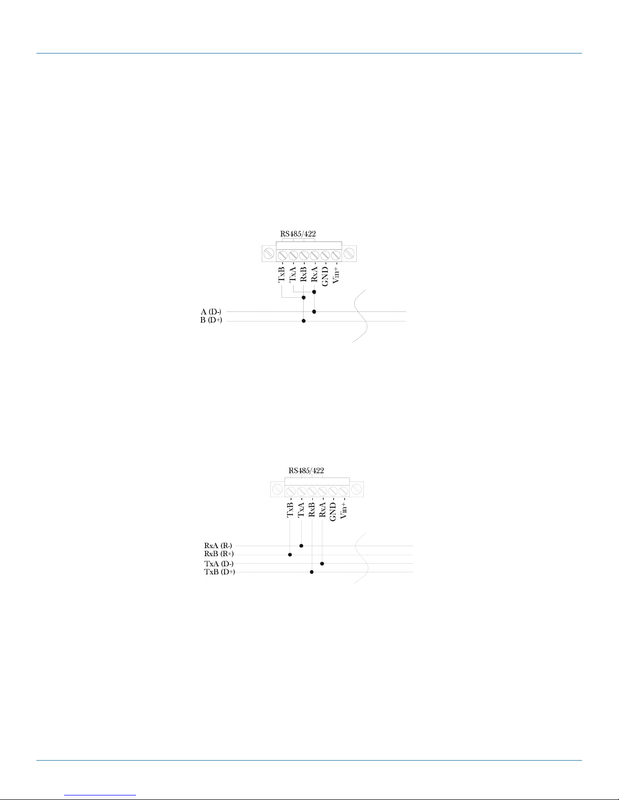
Appendix C: RS-485 Wiring
Appendix C: RS-485 Wiring
The MDR100A-R5 or MDR112A-R5 can be connected into a 2-wire or 4-wire RS-485 network. Terminate the transmission line
only at the extreme ends of the data line if the RS-485 network runs at high data rates and has a long wiring run.
2-wire RS-485
Figure C-1 shows a typical two-wire configuration for an RS-485 connection to a MDR100A-R5 or MDR112A-R5. Two wires are
shared for transmitting and receiving in a 2-wire configuration, so the modem must seize the line at the right time when it transmits. Note again that a transmission line termination is required if the system has high data rates and long wiring runs.
Figure C-1. 2-wire RS-485 Configuration.
4-wire RS-485
A MDR100A-R5 or MDR112A-R5 can also be connected into a RS-485 network in a four-wire configuration as shown in Figure
C-2. In a four-wire network, one node must be a master node and all others must be slaves. The network is connected so that the
master node communicates to all slave nodes. All slave nodes communicate only with the master node. Since the slave nodes
never listen to another slave response to the master, a slave node cannot reply incorrectly to another slave node.
Figure C-2. 2-wire RS-45 Configuration.
Page 58
724-746-5500 | blackbox.com
Page 59

Appendix D: Troubleshooting
Appendix D: Troubleshooting
D.1 Contacting Black Box
If you determine that your Industrial 900-MHz Wireless Modem is malfunctioning, do not attempt to alter or repair the unit. It
contains no user-serviceable parts. Contact Black Box Technical Support at 724-746-5500 or info@blackbox.com. Before you do,
make a record of the history of the problem. We will be able to provide more efficient and accurate assistance if you have a
complete description, including:
• the nature and duration of the problem.
• when the problem occurs.
• the components involved in the problem.
• any particular application that, when used, appears to create the problem or make it worse.
• Host computer make and model.
• Type of operating system installed (e.g. Windows 8, Mac OS X, etc.).
• Make and model of the USB 3.0 device attached to the product.
• Description of the installation.
• Description of the problem.
D.2 Shipping and Packaging
If you need to transport or ship your Industrial 900-MHz Wireless Modem:
• Package it carefully. We recommend that you use the original container.
• If you are returning the unit, make sure you include everything you received with it. Before you ship for return or repair,
contact Black Box to get a Return Authorization (RA) number.
724-746-5500 | blackbox.com
Page 59
Page 60

Black Box Tech Support: FREE! Live. 24/7.
Tech support the
way it should be.
Great tech support is just 60 seconds away at 724-746-5500 or blackbox.com.
About Black Box
Black Box provides an extensive range of networking and infrastructure products. You’ll find everything from cabinets and racks
and power and surge protection products to media converters and Ethernet switches all supported by free, live 24/7 Tech support
available in 60 seconds or less.
© Copyright 2015. Black Box Corporation. All rights reserved. Black Box® and the Double Diamond logo are registered trademarks of BB Technologies, Inc.
Any third-party trademarks appearing in this manual are acknowledged to be the property of their respective owners.
MDR100A-R5, MDR112A-R5 user manual, version 1
724-746-5500 | blackbox.com
 Loading...