

Page 1
June 2015
CUSTOMER
SUPPORT
INFORMATION
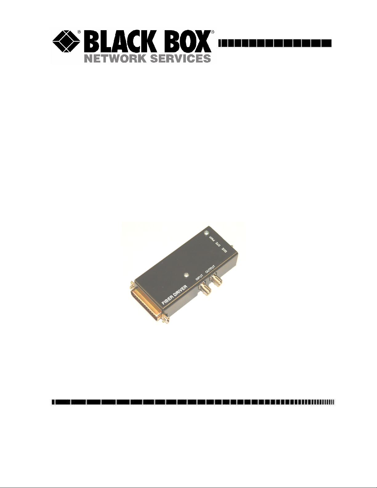
Fiber Driver - ST/DB25F MD940A-F
Fiber Driver - ST/DB25M MD940A-M
FIBER DRIVER
Order toll-free in the U.S.: 877-877-BBOX (outside U.S. call 724-746-5500)
FREE technical support, 24 hours a day, 7 days a week: Call 724-746-5500 or fax 724-746-0746
Mail order: Black Box Corporation, 1000 Park Drive, Lawrence, PA 15055-1018
Web site: www.blackbox.com • E-mail: [email protected]
Part Numbers
MD940A-F
MD940A-M
Page 2
Specifications
Power
Wall-mount Power Supply, 100-240 VAC/47-63 Hz Input,
5 VDC, 1.2 Amp Output, UL/CUL
Interface
EIA RS-232-C; CCITT V.24, V.28; ISO 2110
Flow Control
Will pass XON/XOFF only.
Size
1”H x 2.7”W x 4.2”L
Weight
1.4 lb. includes supply
Data Rate
Transparent to rates up to 76.8 kbps (high/low speed jumper)
Data Format
Asynchronous, Bi-Directional
Connectors
(1) - DB25 female or male, (2) - fiber optic ST
Switches
(1) - DCE/DTE toggle
Fiber Optic Wavelength
850 nm
Receiver Sensitivity
Typical: 3 uW / -25.2 dBm
Transmitter Coupled Power
Actual coupled power varies in fiber optic applications due to mechanical alignment of components and/or
connector and optical fiber tolerances. The Fiber Driver provides a range select feature that allows the user to
compensate for these variations as needed.
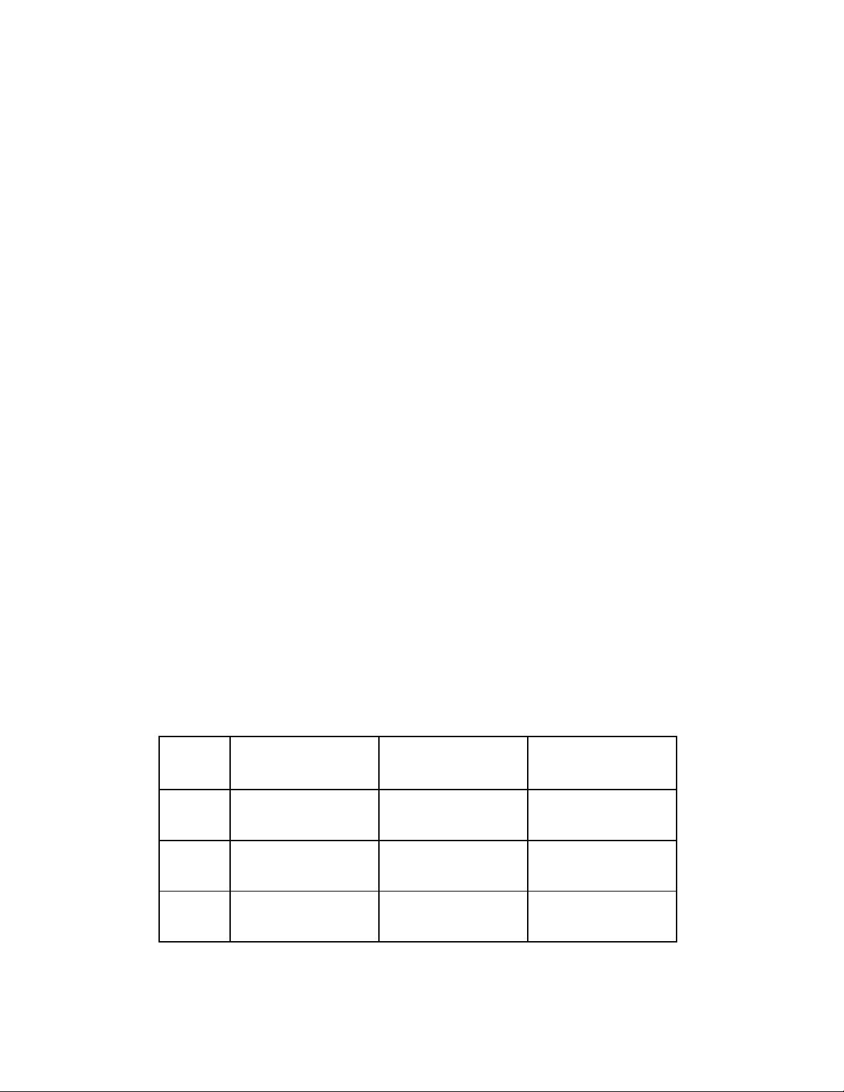
Table 1.1 - Transmitter Coupled Power Settings (W3)
cable type W3=A (short range)
(uW/dBm)
W3=B (medium range)
(uW/dBm)
W3=C (long range)
(uW/dBm)
multimode
50/125 um
multimode
62.5/125 um
Multimode
100/140 um
4.0/-24.0 12.0/-19.2 20.0/-17.0
10.0/-20.0 28.0/-15.5 46.0/-13.4
24.0/-16.2 72.0/-11.4 120/-9.2
(NOTE: Set jumper W3 to the lowest power setting for your application to avoid saturating the far-end unit’s
receiver.)
Page 3
Example Power Budget and Distance Calculations
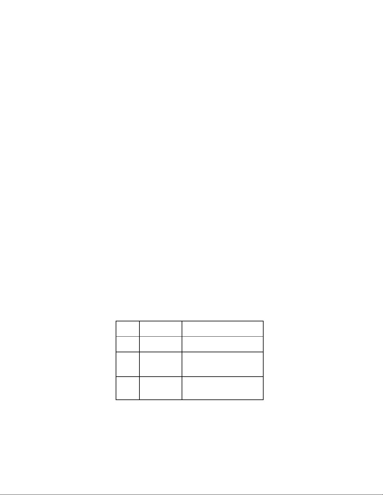
Jumper
Function
Power Budget = Transmitter Output - Receiver Sensitivity
Distance = Power Budget ÷ Loss/km
Example:
Receiver Sensitivity = -25.2 dBm
Transmitter Output = -13.4 dBm
Fiber cable Loss/km = 3.5 dB/km
Power Budget = 11.8 dB
Distance = 3.4 km
Introduction
The Fiber Driver converts standard RS-232 signals into fiber optic signals, which can then be transmitted over
several kilometers depending on cable type and power setting. These devices support asynchronous, bi-directional
RS-232 data transmission. They are switch selectable for either DTE or DCE applications, eliminating the need for
special cables and preventing confusion during installation. They can be ordered with male or female DB25
connectors for the RS-232 interface. Two units are connected using 50, 62.5, or 100 micron multi-mode fiber optic
cable with ST style connectors.
Installation
Before you begin, make sure all equipment is powered off, including the Fiber Drivers.
Remove the two screws and lift off the cover to access the internal configuration jumpers on the Fiber Driver. Set
jumpers W1, W2, and W3 as appropriate for your application (see Figure 3.1 and Table 3.1). Reinstall the cover, and
then set toggle switch S1 for either DTE to connect to a PC, or DCE to connect to a modem. Connect the two fiber
drivers using multi-mode fiber optic cables with ST style connectors. Make certain that the transmitter output of
each unit is connected to the receiver input of the other unit. Next, connect the Fiber Drivers to your RS232 devices,
either by attaching the Fiber Drivers directly to the RS232 connector on your devices, or using straight through
cables. Power up the Fiber Drivers, and then apply power to your equipment.
Use
*Range selection is dependent upon the core size of the fiber optic cable used and the distance data is to be
transmitted. Select the shortest range that accurately passes data.
W1 Pull-up to +5 Install to assert pin 6 on DB25
W2 High speed filter Install to operate at rates above
19.2 kbps
W3 Range select* A-short range, B-medium range,
C-long range
Page 4
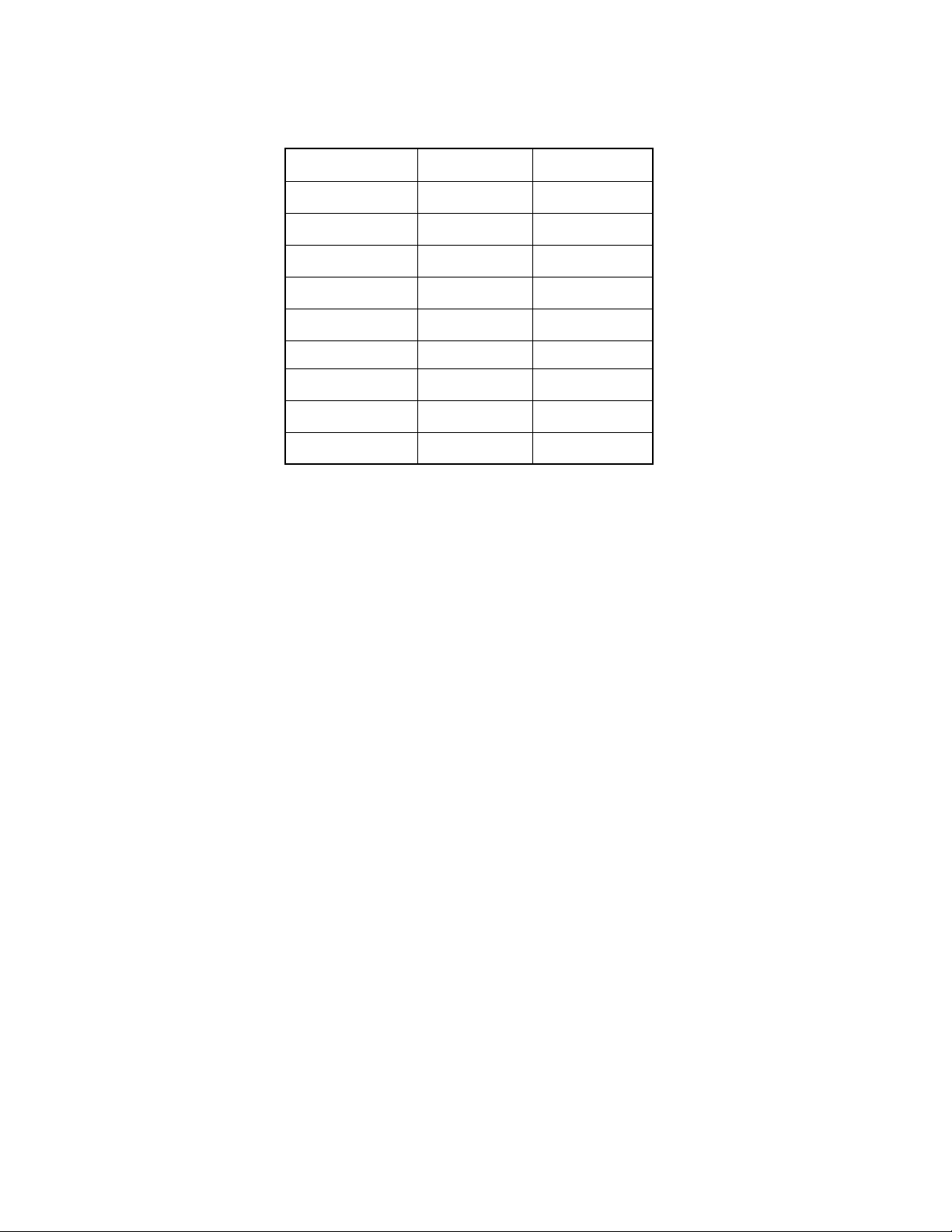
Table 3.2 - RS232 Connector (J1)
Pin - Signal
S1 set to DCE
S1 set to DTE
2 - Transmitted Data Output
3 - Received Data
4 - Request To Send
5 - Clear To Send
6 - Data Set Ready
(note 1)
7 - Common
8 - Data Carrier Detect connected to pin 20 connected to pin 20
20 - Data Terminal
Ready
22 - Ring Indicator
Input
connected to pin 5 connected to pin 5
connected to pin 4 connected to pin 4
Pulled High
Ground
connected to pin 8 connected to pin 8
Open
Input
Output
Pulled High
Ground
Open
DCE - Data Carrier Equipment
DTE - Data Terminal Equipment
Set toggle switch S1 for either DTE to connect to a PC, or DCE to connect to a modem.
Note:
1. Pin 6 (DSR) is pulled to +5 volts through jumper W1. Please see Table 3.1 for details.
Troubleshooting
If the Fiber Drivers fail to operate check the following before calling for technical support.
1. Are both units powered on? Check to see if the power supplies are plugged into a working AC outlet.
2. Check to see if the inter-connect fiber optic cable is connected properly; transmitter to receiver.
3. Check to see if the DCE/DTE setting is appropriate for the interfacing equipment.
4. Check transmitter power settings.
Page 5
FEDERAL COMMUNICATIONS COMMISSION
AND
INDUSTRY CANADA
RADIO FREQUENCY INTERFERENCE STATEMENTS
This equipment generates, uses, and can radiate radio-frequency energy, and if not installed and used properly, that
is, in strict accordance with the manufacturer’s instructions, may cause interference to radio communication. It has
been tested and found to comply with the limits for a Class A computing device in accordance with the
specifications in Subpart B of Part 15 of FCC rules, which are designed to provide reasonable protection against
such interference when the equipment is operated in a commercial environment. Operation of this equipment in a
residential area is likely to cause interference, in which case the user at his own expense will be required to take
whatever measures may be necessary to correct the interference.
Changes or modifications not expressly approved by the party responsible for compliance could void the user’s
authority to operate the equipment.
This digital apparatus does not exceed the Class A limits for radio noise emission from digital apparatus set out in
the Radio Interference Regulation of Industry Canada.
Le présent appareil numérique n’émet pas de bruits radioélectriques dépassant les limites applicables aux appareils
numériques de la classe A prescrites dans le Règlement sur le brouillage radioélectrique publié par le Industrie
Canada.
© Copyright 2015 Black Box Corporation. All rights reserved.
1000 Park Drive • Lawrence, PA 15055-1018 • 724-746-5500 • Fax 724-746-0746
 Loading...