

Page 1

CUSTOMER
SUPPORT
INFORMATION
Order toll-free in the U.S. 24 hours, 7 A.M. Monday to midnight Friday: 877-877-BBOX
FREE technical support, 24 hours a day, 7 days a week: Call 724-746-5500 or fax 724-746-0746
Mail order: Black Box Corporation, 1000 Park Drive, Lawrence, PA 15055-1018
Web site: www.blackbox.com • E-mail: info@blackbox.com
FEBRUARY 1996
MD640A-ST-R2
MD640A-SMA-R2
MD640AE-ST-R2
MD640AE-SMA-R2
MultiMode FOMs -ST and -SMA
MultiMode FOM
Test
Modes
POWER
TD RD CDRTS
Remote
Normal
Local
Page 2

Contents
Chapter Page
1. Specifications ............................................................................................. 1
2. Introduction ............................................................................................... 3
2.1 Features ............................................................................................... 3
2.2 Description .......................................................................................... 4
3. Configuration ............................................................................................. 5
4. Installation .................................................................................................. 8
4.1 Single-Fiber Connection ..................................................................... 8
4.2 RS-232 Connection ............................................................................. 9
5. Operation ................................................................................................. 10
5.1 LED Indicators .................................................................................. 10
5.2 Power-Up ........................................................................................... 11
5.3 Loopback-Test Modes ....................................................................... 11
5.4 Power-Down ....................................................................................... 12
6. Troubleshooting ...................................................................................... 13
6.1 Calling Black Box .............................................................................. 13
6.2 Shipping and Packaging ................................................................... 13
Appendix: RS-232 Pinout .............................................................................. 14
Page 3

MULTIMODE FOMS -ST AND -SMA
TRADEMARKS USED IN THIS MANUAL
ST is a registered trademark of AT&T.
Any other trademarks mentioned in this manual are acknowledged to be the property
of the trademark owners.
Page 4

1
CHAPTER 1: Specifications
Cable Required — (1) Multimode fiberoptic cable, 62.5-µm core
Interface — EIA RS-232/CCITT V.24, DCE
Protocols — Asynchronous or synchronous
Clock — Internal or external from attached RS-232 device
Flow Control — Transparent hardware (RTS/CTS and DTR/DSR
passed through from DTE) or local hardware or
software (RTS/CTS or X-ON/X-OFF), userselectable
Operating Mode — Point-to-point
Speed — Asynchronous: Up to 38.4 Kbps;
Synchronous: 2.4, 9.6, 19.2, 38.4, 56, 64, 192, or
256 Kbps
Maximum
Distance — 2.5 km (1.5 mi.) at all data rates,
5 km (3.1 mi.) at data rates of 64 Kbps or below
Modulation — 3B4B
Wavelength — 880 nm
Attenuation — 14 dB
LED-Responsivity
Minimum — 0.12 amps per watt
User Controls — (2) External:
(1) Front-mounted rocker switch: Test;
(1) Bottom-mounted 8-position DIP switch:
Async/sync operation, data rates, clock source,
flow control
1. Specifications
Page 5

2
MULTIMODE FOMS -ST AND -SMA
Indicators — (6) Front-mounted LEDs: TD, RD, RTS, CTS, Power,
Test
Diagnostics — Local and remote loopback
Connectors — (3) Rear-mounted:
(1) DB25 female;
(1) Barrel-type power jack;
Units with “-ST” suffix: (1) ST female;
Units with “-SMA” suffix: (1) SMA female
Power — For 120-VAC, 60-Hz operation:
From wallmount power supply:
Input: 115 VAC, 60 Hz, 100 mA;
Output: 10 VAC, 700 mA;
For 240-VAC, 50-Hz operation:
From desktop power supply:
Input: 230 VAC, 50 Hz, 100 mA;
Output: 10 VAC, 700 mA
MTBF — 125,000 hrs.
Maximum
Altitude — 10,000 ft. (3048 m)
Temperature — 32 to 140˚ F (0 to 60˚ C)
Humidity — Up to 95% noncondensing
Size — 1.5"H x 4.1"W x 5"D (3.9 x 10.5 x 12.7 cm)
Weight — 5 lb. (2.3 kg)
Page 6

3
CHAPTER 2: Introduction
MultiMode FOMs are fiberoptic short-range modems with a special moneysaving edge. Many other fiberoptic modems can’t transmit and receive data
through the same port, so they use cables with two fibers. MultiMode FOMs
communicate with each other over a much less expensive single-fiber cable,
across distances of as much as 5 km (3.1 miles).
2.1 Features
• Synchronous or asynchronous operation
• Communicates point-to-point over a single optical fiber
• Local and remote test modes
• Asynchronous data rates up to 38.4 Kbps
• Synchronous data rates up to 256 Kbps
• Distances up to 2.5 kilometers (1.5 miles) at any speed
• Distances up to 5 kilometers (3.1 miles) at speeds of 64 Kbps or less
• Internal or external clocking
• Support for transparent hardware, or local hardware, or local software
flow control
• Available with ST®or SMA connectors
• Tri-state front-panel LED indicators
2. Introduction
Page 7

4
MULTIMODE FOMS -ST AND -SMA
2.2 Description
The MultiMode FOM is a fiberoptic short-range modem for point-to-point
RS-232 communication over a single 62.5-µm fiber, such as one of those
bundled into our bulk multifiber cables EFN1004 and EFN1006. The FOM
supports synchronous data rates up to 256 Kbps, and asynchronous data rates
up to 38.4 Kbps. It can also support transparent hardware flow control or
local flow control; in the local setting, it automatically adapts to either
hardware or software flow control. Synchronous timing can be set for
internal or external (from attached RS-232 device) clock.
The MultiMode FOM features extended-data-rate circuitry that allows for
single-fiber distances between 1.5 and 3.1 miles (2.5 and 5 km). Depending
on which model you have, you can connect optical cable with ST or SMA
connectors to the FOM. The MultiMode FOM encodes your data signals
using 3B4B modulation, then converts them to an 880-nm optical signal.
The MultiMode FOM features two test modes: local and remote loopback.
You can activate either of these tests with the FOM’s front-panel toggle switch.
The local loopback test is used to evaluate the DTE-to-modem connection.
The remote loopback test is used to evaluate the condition of the connection
between the modems.
Page 8
5
CHAPTER 3: Configuration
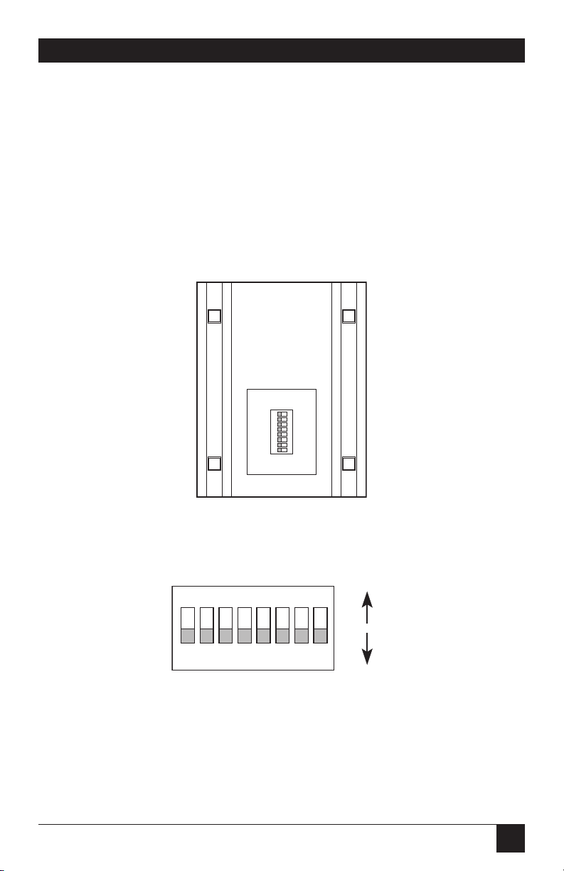
With the MultiMode FOM’s external DIP switch, you can configure the unit
for many different combinations of data rates and clocking methods for
synchronous or asynchronous applications. (Since the FOM has no internal
jumpers or other internal controls, you don’t have to open the unit’s case to
configure the unit.) Figures 3-1 and 3-2 below and Table 3-1 on the next page
show the location of the switch and the switch positions’ identities, settings,
and functions.
Figure 3-2. Closeup of the DIP switch positions showing
ON/OFF settings and position numbers.
1
ON
2
3 4 5 6 7 8
ON
OFF
Figure 3-1. The location of the DIP
switch on the underside of the unit.
1
ON
2
3 4 5 6 7 8
REAR
FRONT
3. Configuration
Page 9

6
MULTIMODE FOMS -ST AND -SMA
This section provides detailed information about the function of each
DIP switch position, and lists all possible settings. Use this section as a
configuration guide for applications where the FOM’s default settings
would not provide correct results. (Position 1 is reserved for future use.)
Positions 2 though 5: Data Rate (Sync. Mode)
Switches 2 through 5 determine two configuration parameters: synchronous
or asynchronous data rate and the mode of synchronization (Sync. Mode)
between two FOMs. Here’s how the packet-spacing option works: The “2X”
setting doubles the space between data packets compared to the “1X” setting,
so that each packet is more easily distinguishable from those before and after
it. This offsets some of the effects of signal degradation over distance, and
allows communication over as much as 5 km (3.1 miles) as opposed to the
“1X” setting’s limit of 2.5 km (1.5 miles). Table 3-2 at the top of the next
page shows every possible setting for these four switch positions.
Position 6: Reset
You can use position 6 to reset the MultiMode FOM without powering down
the unit. Move position 6 to ON to put the FOM in “reset conditon,” then
move position 6 back to OFF (the default setting) to put the FOM back in
“operating condition” (resume normal operation). Don’t leave position 6
ON: the FOM will not work properly unless this switch position is OFF.
Position Function Factory Default
1 RESERVED OFF
2 Data Rate (Sync Mode) ON
3 Data Rate (Sync Mode) OFF
4 Data Rate (Sync Mode) OFF
5 Data Rate (Sync Mode) ON
6 Reset OFF
Operating Mode
7 Handshaking ON Control Signal Mode
8 Clocking Method OFF Internal Clock
0 to 19.2
Async (2X)
}
Table 3-1. Summary of Switch Settings, Showing Factory Defaults
Page 10

7
CHAPTER 3: Configuration
Table 3-2. Possible Settings of DIP Switch Positions 2 Through 5
Pos. 2 Pos. 3 Pos. 4 Pos. 5 Data Rate (Sync. Mode)
ON OFF OFF ON Async 0 to 19.2 Kbps (2X)
ON OFF OFF OFF Async 0 to 38.4 Kbps (1X)
ON ON ON OFF Sync at 2.4 Kbps (1X)
OFF ON ON OFF Sync at 9.6 Kbps (1X)
OFF ON ON ON Sync at 9.6 Kbps (2X)
ON ON OFF OFF Sync at 19.2 Kbps (1X)
ON ON OFF ON Sync at 19.2 Kbps (2X)
OFF ON OFF OFF Sync at 38.4 Kbps (1X)
OFF ON OFF ON Sync at 38.4 Kbps (2X)
ON OFF ON OFF Sync at 48 Kbps (1X)
ON OFF ON ON Sync at 48 Kbps (2X)
OFF OFF ON OFF Sync at 56 Kbps (1X)
OFF OFF OFF OFF Sync at 64 Kbps (1X)
OFF OFF OFF ON Sync at 64 Kbps (2X)
OFF OFF ON ON Sync at 192 Kbps (1X)
ON ON ON ON Sync at 256 Kbps (1X)
Position 7: Handshake Mode
Use position 7 to set the type of flow control. (This switch position must be
moved to the same setting on both FOMs.) If position 7 is set to ON (the
default setting), the Multimode FOMs perform transparent hardware flow
control by passing the RTS/CTS and DTR/DSR signal pairs from the
attached DTEs across the modem link. In this setting, when one FOM drops
the RS-232 “RTS” signal, the other FOM drops the “CTS” signal, and when
one FOM drops the “DTR” signal, the other drops the “DSR” signal.
If position 7 is set to OFF (the “standard modem” setting), each FOM
independently performs flow control between itself and the local DTE,
automatically adapting to either hardware (RTS/CTS) or software
(X-ON/ X-OFF) flow control.
Position 8: Clock Source
Use position 8 to set the clock source. The MultiMode FOM works from an
internal clock if position 8 is set to OFF (the default setting) and provides this
clock signal on RS-232 Pin 15. The FOM receives an external clock from the
attached RS-232 device on RS-232 Pin 24 if position 8 is set to ON.
Page 11

8
MULTIMODE FOMS -ST AND -SMA
The MultiMode FOM is easy to install. After configuring the DIP switch,
simply connect the single-fiber and RS-232 cable to the FOM, plug the power
supply’s output cord into the unit, and plug the power supply into an outlet.
Figure 4-1 shows the location of the interface connections on the MultiMode
FOM’s rear panel.
4.1 Single-Fiber Connection
These short-range modems are designed to work in pairs. You’ll need one at
each end of a single 62.5-µm core, multimode fiber cable. Depending on the
data-rate setting you select, your cable can be a maximum of 2.5 or 5 km long.
Connect the fiberoptic cable to each MultiMode FOM using a single
connector (either ST or SMA type). Figure 4-2 below shows a closeup
of both connector types.
Figure 4-2. SMA and ST connectors.
SMA
ST
ALIGNMENT PIN
FACES DOWN
Figure 4-1. Rear panel of the MultiMode FOM.
RS-232 INTERFACE
POWER FIBER
4. Installation
Page 12

9
CHAPTER 4: Installation
4.2 RS-232 Connection
To connect the MultiMode FOM to a DTE (Data-Terminal Equipment: a PC,
host, terminal, etc.), use a straight-through RS-232 cable. To connect the
MultiMode FOM to a DCE (Data-Communications Equipment: a modem,
multiplexor, etc.), use a cross-pinned RS-232 cable of the null-modem type.
Whether the cable is straight-through or cross-pinned, it must have a male
DB25 connector on the FOM end.
Page 13

10
MULTIMODE FOMS -ST AND -SMA
Once you have configured each MultiMode FOM properly (see Chapter 3)
and installed them and their fiber and RS-232 cables (see Chapter 4), you are
ready to operate the units. This chapter describes how to (a) interpret the
LED indicators, (b) power the units up and down, and (c) use the built-in
loopback-test modes.
5.1 LED Indicators
The MultiMode FOM’s six front-panel status LEDs indicate the condition of
the modem and communication link. Figure 5-1 below shows the location of
each LED; after Figure 5-1 is a description of each LED’s function.
• The green “Power” LED glows if the modem is plugged in and getting
power.
• The green “Test Modes” LED glows when the modem has been set to
perform a local analog or remote digital test.
• The “TD” and “RD” indicators blink red or green in response to data
activity (transmitting data or receiving data respectively). Red indicates a
“low” level of RS-232 logic; green indicates a “high” level of RS-232 logic.
These LEDs will continuously glow red if the RS-232 cable connections
are correct and the RS-232 device to which the FOM is attached is not
transmitting or receiving data (this is equivalent to a constant “low” state).
• The “RTS” and “CD” indicators are also tri-state and will glow red for a
“low” signal or green for a “high” signal. The RTS LED lights in response
an incoming signal on RS-232 Pin 4 (normally Ready to Send). The CD
LED lights (a) in response to an incoming Carrier Detect signal on the
line side (from the remote FOM) and (b) when, as a result, the FOM
outputs the same signal on RS-232 Pin 8.
Figure 5-1. Front panel of the MultiMode FOM.
POWER
Test
Modes
Remote
Normal
Local
TD RD CDRTS
MultiMode FOM
5. Operation
Page 14

11
CHAPTER 5: Operation
5.2 Power-Up
Apply AC power to the MultiMode FOM by first plugging the output cord of
the FOM’s power supply into the rear-panel power jack, then plugging the
power supply’s input cord into a working AC power outlet. This should
activate the unit immediately—the FOM has no power switch—and the
“Power” LED should light. When both the local and remote MultiMode FOMs
are powered up, and are passing data normally, the LEDs will look like this:
• PWR = green
• TD and RD = flashing red and green
• RTS and DCD = green
• TEST = off
5.3 Loopback-Test Modes
The MultiMode FOM can perform two types of loopback tests that will help
you to evaluate the condition of the FOM pair, the communication link
between them, and the link between each FOM and the attached RS-232
device. These tests are activated from the front panel.
5.3.1 L
OCALLOOPBACK
The local loopback test is an analog test that checks the operation of the local
MultiMode FOM, and is performed separately on each unit. During this test,
any data sent to the local MultiMode FOM by the attached RS-232 device will
be echoed back to that device. For example, characters typed on the keyboard
of a local terminal will appear on the terminal screen.
To perform a local loopback test, follow these steps:
A. Activate local loopback by moving the local MultiMode FOM’s front-
panel toggle switch down to the “Local” setting: This FOM’s transmitted
output is now connected to its own receiver. Its “Test” LED should glow.
(Even though the local FOM cannot communicate with the remote FOM
in this mode, the synchronized connection between the two modems
remains intact.)
B. Verify that the RS-232 device is operating properly and can be used for a
test. If you send data from the RS-232 device and the data is corrupted
when it comes back, call a technician or replace the RS-232 device.
Page 15

12
MULTIMODE FOMS -ST AND -SMA
C. Perform a BERT (bit error rate) test on each FOM. If the BERT test
doesn’t uncover any faults, but the RS-232 device still indicates a fault,
follow the manufacturer’s suggested diagnostic procedures for the
RS-232 device. Also, check the cable between the RS-232 device and the
FOM.
5.3.2 R
EMOTELOOPBACK
The remote loopback test checks the performance of both the local and
remote MultiMode FOMs, and the communication link between them. Any
characters sent to the remote FOM in this test mode will be returned to the
originating device. For example, if your local RS-232 device is a terminal,
characters typed on the terminal’s keyboard will appear on the terminal’s
screen after having been passed to the remote FOM and looped back.
To perform a remote loopback test, follow these steps:
A. Activate remote loopback by moving the remote MultiMode FOM’s
front-panel toggle switch up to the “Remote” setting: this FOM now
automatically echoes data back across the fiberoptic line to the local
FOM. The remote unit’s “Test” LED should glow. (As with the local
loopback test, the synchronized connection between the two modems
remains intact during this test.)
B.Perform a BERT (bit error rate) test on the system.
C.If the BERT test equipment indicates a fault, and the local loopback test
was successful for both MultiMode FOMs, this suggests a problem with
the fiber cable connecting the modems. You should test the cable for
proper connections and continuity.
5.4 Power-Down
To turn off the MultiMode FOM, unplug its power supply from the outlet.
The FOM has no power switch.
Page 16

13
CHAPTER 5: Operation
6.1 Calling Black Box
If you determine that your MultiMode FOM is malfunctioning, do not
attempt to alter or repair the unit. Contact Black Box Technical Support.
Before you do, make a record of the history of the problem. We will be
able to provide more efficient and accurate assistance if you have a complete
description, including:
• The nature and duration of the problem.
• When the problem occurs.
• The components involved in the problem.
• Any particular application that, when used, appears to create the problem
or make it worse.
6.2 Shipping and Packaging
If you need to transport or ship your FOM:
• Package it carefully. We recommend that you use the original container.
• If you are shipping the FOM for repair, make sure you include its power
supply. If you are returning the FOM, make sure you include its manual
as well. Before you ship, contact Black Box to get a Return Materials
Authorization (RMA) number.
6. Troubleshooting
Page 17

14
MULTIMODE FOMS -ST AND -SMA
The figure below shows the pinout of the MultiMode FOM’s rear-mounted
RS-232 port (DB25 female connector).
Appendix: RS-232 Pinout
14
From FOM
16
From FOM
18
19
To FOM
21
22
23
To FOM
25
STANDARD DCE SETTINGDIRECTION
Transmitting Timing
Receiving Timing
Data Term. Ready (DTR)
Transmitting Timing LXC
DIRECTION
1-
14
14
-15
16
16
-17
18
18
19
19
-20
21
21
22
22
23
23
-24
25
25
(FG) Frame Ground
2-
(TD) Transmit Data
3-
(RD) Receive Data
4-
(RTS) Request to Send
5-
(CTS) Clear to Send
6-
(DSR) Data Set Ready
7-
(SG) Signal Ground
8-
(DCD) Data Carrier Detect
To FOM
From FOM
To FOM
From FOM
From FOM
From FOM
Page 18

1000 Park Drive • Lawrence, PA 15055-1018 • 724-746-5500 • Fax 724-746-0746
© Copyright 1996. Black Box Corporation. All rights reserved.
 Loading...