

Page 1
February 2004
0049-0119-500
MD1970A / MD1970A-DC /MD1970C Modem
Page 2

Contents
CHAPTER 1 INTRODUCTION............................................................................................................................3
SUMMARY OF KEY FEATURES ..........................................................................................................................3
MODELS ...........................................................................................................................................................3
USING THIS MANUAL .......................................................................................................................................3
CHAPTER 2 INSTALLING THE MODEM ...........................................................................................................4
SITE PREPARATION...........................................................................................................................................4
UNPACKING YOUR HARDWARE........................................................................................................................4
ADDITIONAL ITEMS YOU NEED ........................................................................................................................4
HARDWARE OVERVIEW....................................................................................................................................4
CONFIGURING THE MODEM ..............................................................................................................................6
Jumper S1 − Carrier Detect Control...........................................................................................................9
Jumper S2 − Transmit Level........................................................................................................................9
Jumper S3 − 2-wire/4-wire Mode................................................................................................................9
Jumper S4 − Call Turnaround Squelch .......................................................................................................9
Jumper S5 − Transmit Carrier ..................................................................................................................10
Jumper S6 − Local Copy ...........................................................................................................................10
Jumper S8 − Signal and Earth Ground .....................................................................................................10
Jumper S9 − RTS-CTS Delay ....................................................................................................................10
Jumper S10 − Carrier Detect Delay..........................................................................................................11
Jumper S11 − Turnaround Squelch Time..................................................................................................11
Jumper S12 − Soft Carrier Turn Off..........................................................................................................11
Jumper S13 − Anti-Streaming ...................................................................................................................11
Jumpers S14 and S15 − Self Test or Test Pattern......................................................................................12
CONNECTING A DTE ......................................................................................................................................12
CONNECTING TO A PRIVATE LINE COMMUNICATION CIRCUIT........................................................................12
Connecting to a DC Power Source (MD1970A-DC) ................................................................................12
Connecting to an AC Power Source (MD1970C) .....................................................................................13
CHAPTER 3 LEDS AND CONTROLS...............................................................................................................14
FRONT PANEL LEDS ......................................................................................................................................14
FRONT PANEL TEST SWITCH ..........................................................................................................................14
CHAPTER 4 TROUBLESHOOTING ..................................................................................................................17
LOCAL MODEM TEST .....................................................................................................................................17
LINE AND MODEM TEST .................................................................................................................................17
CHAPTER 5 SPECIFICATIONS ........................................................................................................................18
GENERAL........................................................................................................................................................18
DIMENSIONS AND WEIGHT .............................................................................................................................18
TEMPERATURE RANGE ...................................................................................................................................18
POWER REQUIREMENTS..................................................................................................................................19
DC POWER REQUIREMENTS (MD1970A-DC)................................................................................................19
INTERFACE PIN ASSIGNMENTS .......................................................................................................................19
APPENDIX A COMPLIANCES .........................................................................................................................20
FCC REQUIREMENTS FOR TELEPHONE-LINE EQUIPMENT ..............................................................................20
CERTIFICATION NOTICE FOR EQUIPMENT USED IN CANADA..........................................................................20
FEDERAL COMMUNICATIONS COMMISSION AND CANADIAN DEPARTMENT OF
OMMUNICATIONS RADIO FREQUENCY INTERFERENCE STATEMENTS ...........................................................21
C
NORMAS OFICIALES MEXICANAS (NOM) ELECTRICAL SAFETY STATEMENT .................................................21
INSTRUCCIONES DE SEGURIDAD.....................................................................................................................21
Page ii
Page 3

Chapter 1
Introduction
he BLACK BOX® MD1970A standalone modem and MD1970C rack-mount modem are Frequency Shift
Keyed (FSK) modems designed for asynchronous half-duplex communication on 2-wire private line circuits
or full-duplex communication on 4-wire private-line circuits.
T
Summary of Key Features
The following list summarizes the modem’s key features.
• Bell 202T compatible
• Operates over voice-grade leased lines or private lines
• 0 to 1200 bps operation for unconditioned line.
• 0 to 1800 bps operation for conditioned line (C2).
• Point-to-point or point-to-multipoint polling network
• 4-wire full-duplex or 2-wire half-duplex leased-line configuration.
• Analog Loopback Test, Digital Loopback Test, Self Test, and Test Pattern Transmit.
• LED displays for power, RS-232 control, data status, and test mode.
Models
The BLACK BOX® modems are available in three models:
The MD1970A is a desktop modem that comes with an AC power adapter for 115/230 VAC.
The MD1970A-DC is a desktop modem that uses DC power.
The MD1970C is a rack-mount modem that installs into a standard 19-inch rack.
In this manual, the term “modem” will be used to refer to both models collectively. If information pertains to one
model only, that model will be identified by its model number.
Using This Manual
This manual contains all the information you need to install, configure, use, and test your modem.
Chapter 1 contains general information on what the modem does, contents of this manual, and contact
information for Black Box.
Chapter 2 describes how to install and configure the modem.
Chapter 3 provides general operating procedures.
Chapter 4 provides troubleshooting procedures.
Chapter 5 lists the modem’s specifications.
Page 3
Page 4

Installing the Modem
Chapter 2
Installing the Modem
his chapter describes how to install the modem.
T
Site Preparation
The location where you install your modem should be:
• Within six feet of a 115 or 230 VAC grounded outlet not controlled by a wall switch
• No more than 50 feet from the data terminal equipment
• Away from extremes of temperature, humidity, and appreciable shock.
Note:
Be sure that there is a 4-inch minimum space at the back of the modem for signal line and interface cable
clearance.
Unpacking Your Hardware
Your package should include at least one MD1970A or MD1970C modem, one RJ-45 jack-to-4 wire leased line
cable, and this Installation Guide. If your package contents are damaged or missing, please contact your place of
purchase immediately.
Additional Items You Need
To use your modem, you need the following additional items:
All users: an RS-232 cable to connect a data terminal. The cable must conform to the pin assignments shown on
page 19.
Standalone modem users: a two- or four-wire transmission line or leased line and power supply.
Rack-mount modem users: a modem rack and an available slot in the rack for installing the modem.
Hardware Overview
Figures 2-1, 2-2, and 2-3 show the front and back modem panels.
Page 4
Page 5
Installing the Modem
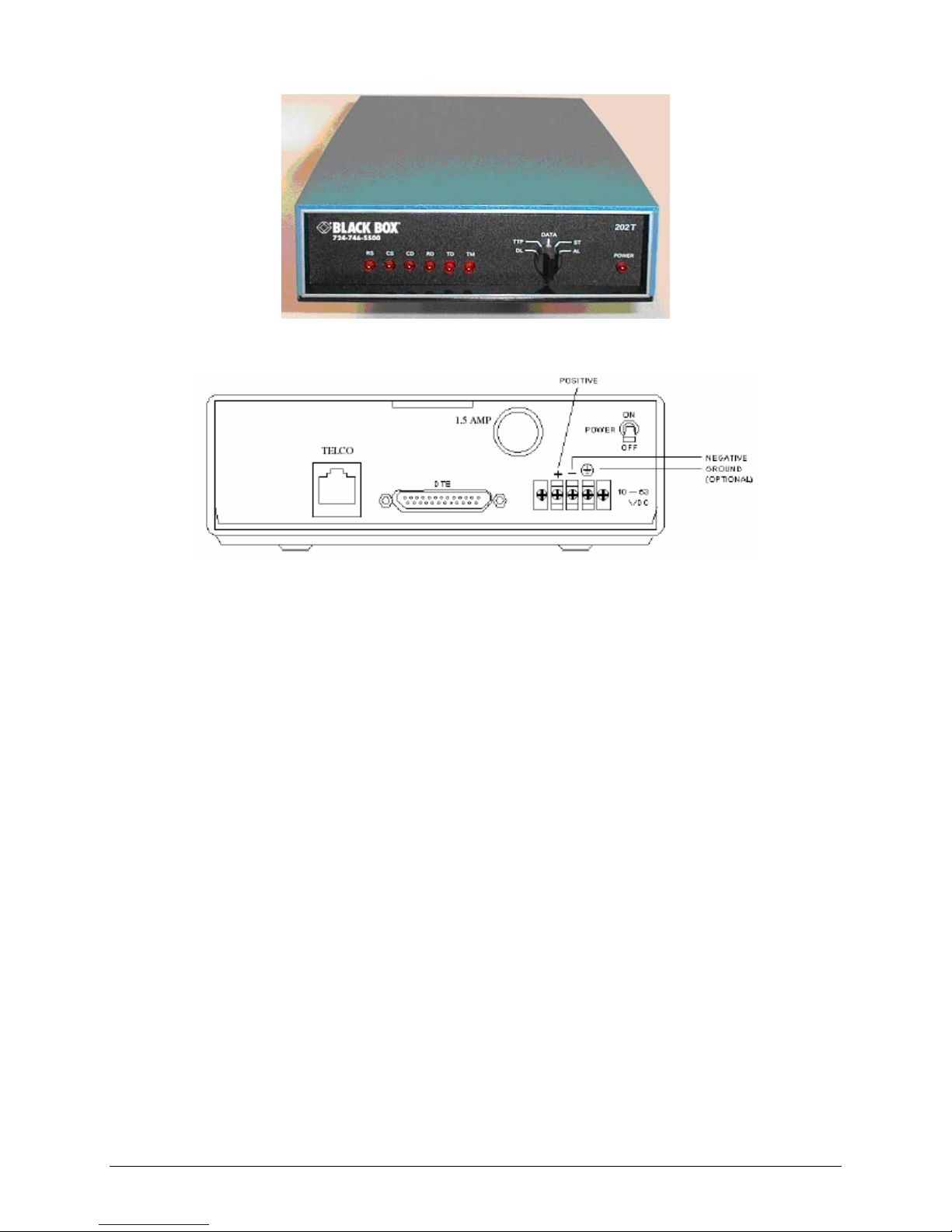
Figure 2-1. Front Panel
Figure 2-2. Back Panel
On the front panel of the modem, there are:
One Power LED and six status LEDs (see page 14)
A rotary test switch (see page 14)
On the back panel of the BLACK BOX® MD1970A modem, there are:
A power cord or power input connector
A power switch for turning the modem on and off
A fuse, 3/8 amp, 250 Volt, slow-blow
A DB25 female connector for accommodating a DTE device
An RJ-45 connector for connecting to a communications line
On the back panel of the MD1970A-DC modem, there are:
A power switch for turning the modem on and off
A fuse, 1.5 amp
A DC power connector
A DB25 female connector for accommodating a DTE device
An RJ-45 connector for connecting to a communications line
Page 5
Page 6

Installing the Modem
Configuring the Modem
The modem obtains some operating characteristics from jumper settings. The default jumper settings are for
common 4-wire full-duplex applications. To reconfigure the modem for 2-wire half-duplex and special applications,
you must change the default jumper settings.
To change jumper settings, push the two tabs on the back of the modem to open the modem cover and gain access to
the jumper settings on the printed circuit board (see Figure 2-4). Then set the jumpers to the desired settings and
replace the cover.
Figure 2-4. Gaining Access to the Modem Jumpers
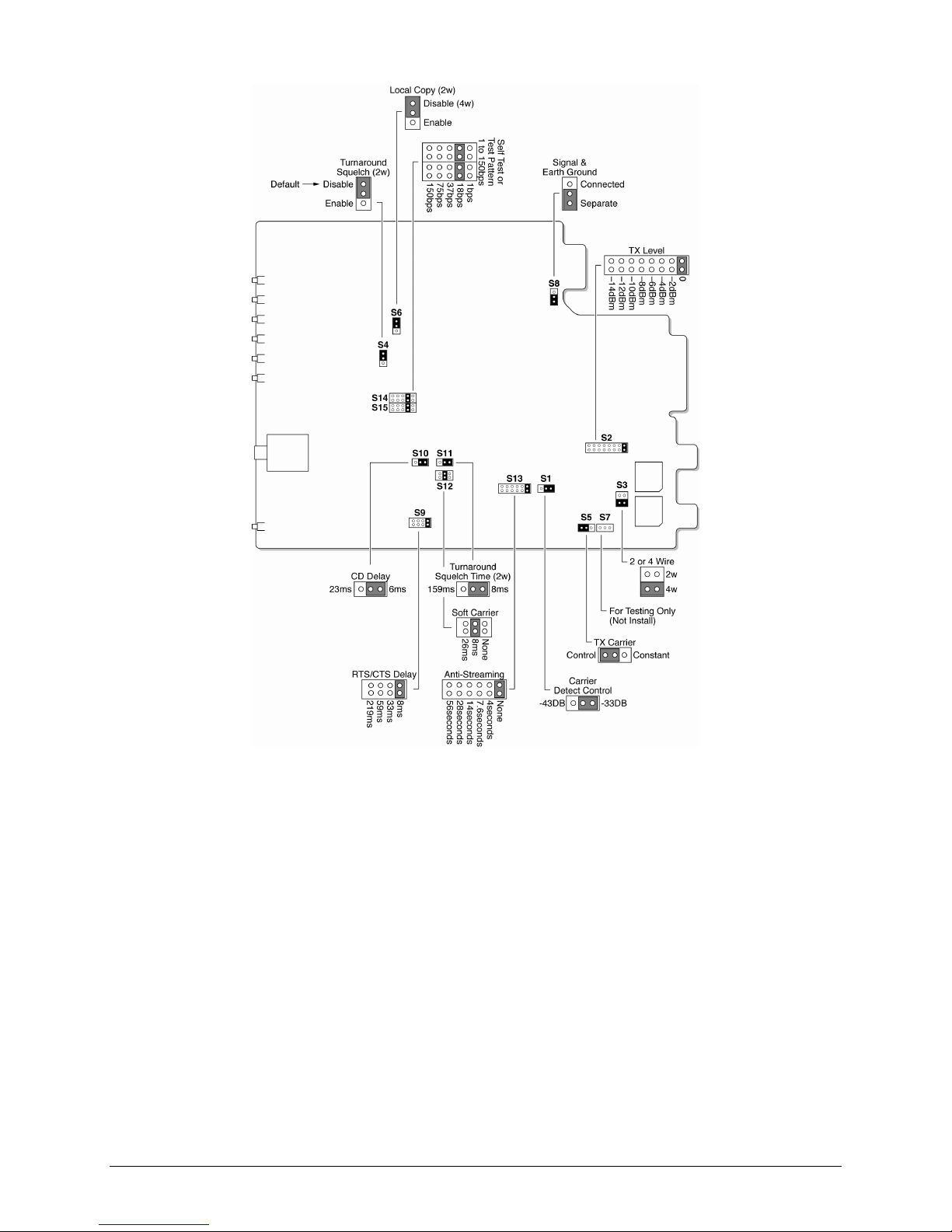
Figure 2-5 on the next page shows the location of the modem jumpers. Table 2-1 on page 8 summarizes the jumper
settings (default settings are bold).
Page 6
Page 7
Installing the Modem
Figure 2-5. Modem Jumper Locations
Page 7
Page 8

Installing the Modem
Jumper Function Settings See Page…
S1
S2
S3
S4
S5
S6
S8
S9
S10
S11 Turnaround squelch time (Enabled by jumper S4) 8 ms
S12
S13
S14 and S15
Table 2-1. Jumper Settings
Carrier Detect control
Transmit level
2-wire/4-wire mode 2-wire
Call turnaround squelch Enabled
Transmit carrier
Local copy Enabled
Signal and Earth ground Connected
RTS-CTS delay
Carrier Detect delay
Soft Carrier turn off None
Anti-streaming
Self Test or test pattern (Tx and Rx pattern speed) 1 bps
-33 dBm
-43 dBm
0dBm
-2 dBm
-4 dBm
-6 dBm
-8 dBm
-10 dBm
-12 dBm
-14 dBm
4-wire
Disabled
Control
Constant
Disabled
Separate
8 ms
33 ms
59 ms
219 ms
6 ms
23 ms
159 ms
8 ms
26 ms
None
4 seconds
7.6 seconds
14 seconds
28 seconds
56 seconds
18 bps
37 bps
75 bps
150 bps
8
9
9
9
10
10
10
10
11
11
11
11
12
Note:
The jumper positions in the following sections reflect the position of the jumpers on the modem board when
you face the board as indicated in Figure 2-5 on page 7.
Page 8
Page 9

Installing the Modem
Jumper S1 − Carrier Detect Control
Settings:
-33 dBm (default)
-43 dBm
Jumper S1 configures the dynamic range of the modem receiver. The selections are either –33 dBm or –43 dBm. If
the incoming signal is above –24 dBm, use the default –33 dBm setting. If the modem is operated on the network,
use the –43 dBm setting.
Jumper S2 − Transmit Level
Settings:
Jumper S2 adjusts the modem’s transmit level. There are eight transmit level settings you can choose. By default,
the modem uses a transmit level of 0 dBm.
0 dBm (default)
-2 dBm
-4 dBm
-6 dBm
-8 dBm
-10 dBm
-12 dBm
-14 dBm
Jumper S3 − 2-wire/4-wire Mode
Settings:
2-wire
4-wire (default)
Jumper S3 configures the modem for 2-wire or 4-wire operation.
When configured for 4-wire full-duplex operation, jumper S5 can be strapped to maintain constant carrier from
the master modem to all slave modems at all times after the initial training. This enables the master modem to
transmit data to the slave modems, with no RTS-to-CTS delay. This is the preferred operating mode when
minimum turnaround is desired.
When configured for 2-wire half-duplex operation, the modem encounters an RTS-to-CTS delay when
transmitting to slave modems, increasing the turnaround time. Set jumper S5 to controlled carrier for 2-wire
half-duplex operation.
Jumper S4 − Call Turnaround Squelch
Settings:
Jumper S4 configures the modem’s Call Turnaround Squelch setting. For 2-wire, half-duplex communications, set
this strap to the Enabled position. In this position, the receiver is inhibited for a period of time after the local
transmitter is turned OFF. This guards against echoes caused by the transmission just completed. The time is
determined by the turnaround squelch time option (jumper S11).
Enabled
Disabled (default)
Page 9
Page 10

Installing the Modem
For 4-wire, full-duplex communications, keep the jumper set to the default position of Disabled.
Jumper S5 − Transmit Carrier
Settings:
Control (default)
Constant
Jumper S5 places the transmitter under terminal control (default) or turns on the transmitter continuously in a 2-wire
half duplex system.
Jumper S6 − Local Copy
Settings:
Jumper S6 must be left is the default position of Disabled when operating on a 4-wire network. It is also normally
left in the default Disabled position when operating on a 2-wire network. Strapping this jumper as Disabled inhibits
the local receiver from receiving the transmission of the local transmitter.
Enabled
Disabled (default)
Jumper S8 − Signal and Earth Ground
Settings:
Connected
Separate (default)
Jumper S8 allows Earth GND to be tied to the modem system GND.
Jumper S9 − RTS-CTS Delay
Settings:
Jumper S9 configures the modem’s RTS-CTS delay. Four choices for selecting an RTS-CTS delay are available.
8 ms (default)
33 ms
59 ms
219 ms
Page 10
Page 11

Installing the Modem
Jumper S10 − Carrier Detect Delay
Settings:
6 ms (default)
23 ms
Jumper S10 configures the modem’s Carrier Detect turn on Delay timing. The delay chosen must be consistent with
the Clear To Send delay selection of the transmitting modem and must be less than the CTS delay. The available
delays are 6 ms (default) and 23 ms. The carrier detect drop out is less than 6 ms.
Jumper S11 − Turnaround Squelch Time
Settings:
Jumper S11 is used with the call turnaround squelch option (jumper S4). The available times are 8 ms (default) and
159 ms.
8 ms (default)
159 ms
Jumper S12 − Soft Carrier Turn Off
Settings:
None
8 ms (default)
26 ms
Jumper S12 configures the modem to either turn off the transmitter immediately upon release of Request To Send,
or send a Soft Carrier Turn Off signal of 900 Hz for 8 or 26 ms at the end of each transmission.
Jumper S13 − Anti-Streaming
Settings:
Jumper S13 lets you select an anti-streaming time or use no anti-streaming at all. Anti-streaming is typically used in
multi-point applications to prevent a malfunctioning slave from occupying the line indefinitely.
When anti-streaming is active, the modem can only transmit data for up to 56 seconds. Thereafter, the modem’s
transmitter is automatically turned off. The modem then looks for an ON-to-OFF transition of Request To Send
(RTS) before proceeding with normal operation.
None (default)
4 seconds
7.6 seconds
14 seconds
28 seconds
56 seconds
Page 11
Page 12

Installing the Modem
Jumpers S14 and S15 − Self Test or Test Pattern
Settings:
Jumpers S14 and S15 configures the modem for Self Test or Test Pattern. When the modem is in local Self Test or
Test Pattern mode, it generates a dot test pattern. The supported baud rates are 1 bps, 18 bps, 37 bps, 75 bps, or 150
bps.
1 bps
18 bps (default)
37 bps
75 bps
150 bps
Connecting a DTE
The modem back panel provides a standard, 25-pin port labeled DTE, which connects to an RS-232 device. The
connectors for this port conform to the pin assignments shown under “DTE Connector – EIA RS-232-C” on page
19.
The DTE should have a cable no longer than 50 feet, with a Cinch or Cannon plug per DB-19604-432 plus a DB51225-1 hood or equivalent.
Connecting to a Private Line Communication Circuit
The modem back panel provides an 8-pin RJ-45 connector labeled TELCO, which connects to a private line
communication circuit. The connectors for this port conform to the pin assignments shown under “Telco Connector”
on page 19.
Connecting to a DC Power Source (MD1970A-DC)
The MD1970A-DC back panel accepts a DC voltage source from 10 to 53 VDC and provides 500 Volts isolation.
Figure 2-3 on page 5 shows this connector. The MD1970A-DC modem comes with a grounded power cable for
attaching the modem to an acceptable DC power source. To attach this cable to the DC power connector on the back
panel:
1. Connect the positive wire from the supplied cable to the positive terminal block (labeled +) on the DC power
connector. Facing the back of the modem, this is the left terminal block.
2. Connect the negative wire from the supplied cable to the negative terminal block (labeled –) on the DC power
connector. Facing the back of the modem, this is the middle terminal block.
3. Connect the ground wire from the supplied cable to the earth ground terminal block (labeled
power connector. Facing the back of the modem, this is the right terminal block.
Note:
Connecting the ground wire to earth ground is optional for operation. However, it is strongly recommended
that you make this connection because doing so provides surge protection for the modem.
) on the DC
Page 12
Page 13

Installing the Modem
Connecting to an AC Power Source (MD1970A)
The MD1970A comes with an AC power adapter that connects to a 115/230 VAC power source. On the secondary
voltage side, the power adapter connects to the power block on the back of the modem. When making this
connection to the modem, align the power adapter with the positive and negative markings on the modem rear
panel.
Powering-on the Modem
To supply power to the modem, place the POWER ON switch on the modem back panel to the ON position. The
PWR LED on the front panel goes ON.
Powering-off the Modem
To turn off power to the modem, place the POWER ON switch on the modem back panel to the OFF position. The
PWR LED on the front panel goes OFF.
Page 13
Page 14

his chapter describes the LEDs and controls on the modem.
Chapter 3
LEDs and Controls
T
Front Panel LEDs
Table 3-1 describes the LEDs on the modem front panel.
Front Panel Test Switch
The modem front panel has a five-position rotary switch that lets you select the modem’s operating mode. The five
switch positions are:
Table 3-1. Front Panel LEDs
LED Status
PWR
TM
CD
RD
RS
CS
TD
ON = power is being supplied to the modem.
ON = the rotary switch is turned to Analog or Digital Loopback, or the switch is in the Test
Pattern transmit mode or Self Test mode and no error is detected.
ON = the modem is detecting a valid carrier.
ON = data is being received or receive data line is in a space condition.
ON = the Request-to-Send line from the DTE is ON.
ON = the Clear-to-Send line from the modem is ON.
ON = data to be transmitted is being furnished to the modem.
DATA use this position for normal data transmissions.
AL (Analog Loopback) this position prepares the modem for testing by the local terminal device. The
transmitter output of the modem is disconnected from the output coupling transformer and connected to the
modem receiver input. See Figure 3-1.
DL (Digital Loopback) this position configures the modem to loop back received data to the transmitter and
transmit the data to the remote end. The RS-232-C interface to the terminal is not active during this test. See
Figure 3-2.
ST (Self Test) this position inhibits the modem from transmitting and receiving data on the COMM LINE.
The RS-232-C interface to the terminal is not active during this test. See Figure 3-3.
The test pattern (dot pattern) passes through the transmitter, loops back into the receiver, is demodulated, and is
checked for errors. If errors occur, the TM LED turns OFF and remains OFF for a period of time that depends
on the pattern generator baud rate.
In Analog Loopback and Self Test modes, the received analog data is buffered, amplified by 16 dB (if output
level is set to 0 dB), and routed out on the transmit analog pair.
TTP (Transmit Test Pattern) this setting forces the transmitter on and transmits data from the test generator
to the COMM LINE. The RS-232-C interface lines (RTS, CTS, and Transmit Data) to the transmitter are not
Page 14
Page 15

LEDs and Controls
active. See Figure 3-4.
The TM LED goes ON when the receive data is good. If there are errors, or if the received data does not
compare with the transmitted data, the TM LED goes off. The RS-232-C interface lines to the receiver are
active during this mode.
Remote Modem
Data Mode
TRANSMITTER
RECEIVER
DTE
DTE
RXD
TXD
Local Modem
Analog LoopBack Mode
RECEIVER
PAD
TRANSMITTER
Amplifier
4-Wire Telephone Line
Figure 1 - Analog Loopback Test
Figure 3-1. Analog Loopback Test
Local Modem
Local Digital LoopBack Mode
RECEIVER
DTE DTE
TRANSMITTER
Remote Modem
Data Mode
TRANSMITTER
RECEIVER
4-Wire Telephone Line
Digital Loopback Test
Figure 3-2. Digital Loopback Test
Page 15
Page 16

LEDs and Controls
Modem
Self Test Mode
DTE
TEST PATTERN TRANSMITTER
ERROR CHECK RECEIVER
TM
PAD
Amplifier
4-Wire Telephone Line
TX
RX
Self Test
Figure 3-3. Self Test
Remote Modem
Local Modem
Send Test Pattern Mode
SPEED SELECT
DTE DTE
TEST
PATTERN
TRANSMITTER
Receive Test Pattern Mode
RECEIVER
ERROR
CHECK
TM
2-Wire Telephone Line
Transmit Test Pattern
Figure 3-4. Transmit Test Pattern
Page 16
Page 17

his chapter describes troubleshooting procedures you can use in the unlikely event you encounter a problem with
your modem.
T
Local Modem Test
The local modem test verifies the local modem’s transmitter, receiver, and connection to the locally attached DTE.
This test can be run either by generating a data pattern from the locally attached DTE or by having the modem
generate a test pattern.
The following procedure describes how to run the local modem test using a locally attached DTE to generate a data
pattern.
1. Using the front panel test switch, place the modem in Analog Loopback mode.
2. Turn on the Request To Send line.
3. Use the locally attached DTE to transmit the data pattern and check for data errors on the Receive Data line.
Chapter 4
Troubleshooting
The following procedure describes how to run the local modem test using the modem test pattern instead of a data
pattern originated by the local DTE.
1. Using the front panel test switch, place the modem in Self Test mode.
2. The TM indicator should turn ON. If the indicator turns OFF or flashes, errors are occurring.
Line and Modem Test
The line and modem test verifies the local modem, the remote modem, and the communications line between them.
With this test, the local modem loops back received data to the transmitter and transmits the data to the remote
modem. These characters can originate either from a locally attached DTE or by having the modem generate a test
pattern.
The following procedure describes how to run the line and modem test using a locally attached DTE to generate a
data pattern.
1. Place the remote modem in Digital Loopback mode.
2. Place the local modem in Data mode and transmit a data pattern. Check for data errors on the Receive Data line
The following procedure describes how to run the line and modem test using the modem test pattern instead of a
data pattern originated by the local DTE.
1. Place the remote modem in Remote Test mode.
2. Place the local modem in Remote Self Test mode. The TM LED should turn ON and remain ON if the data is
error free.
Page 17
Page 18

his chapter lists the specifications for the modem.
Chapter 5
Specifications
T
General
Operation:
Data rate:
Modulation:
Carrier frequencies:
Line impedance:
Transmitter output level:
RTS-CTS delay:
Carrier Detect delay:
Digital interface:
Package:
Turnaround squelch:
Anti-streaming:
Test features:
2-wire half-duplex or 4-wire full-duplex private line operation.
0-1200 bps asynchronous on worst case line. 0-1800 asynchronous on C2
conditioned line
Phase coherent. Frequency Shift Keyed (FSK)
Mark 1200 Hz ±1%
Space 2200 Hz ±1%
600 ohms ±10% transformer coupled and transient protected.
Selectable from 0 to –14 dBm, in 2 dB steps.
8, 33, 59, or 219 ms
6 or 23 ms OFF-to-ON, 6 On-to-OFF
EIA RS-232-C and CCITT V.24.
Standalone, UL approved.
8 ms or 159 ms
Option to turn transmitter OFF after selected time, even if RTS is ON
Self Test, Analog Loopback, Digital Loopback, and Test Pattern Transmit
Dimensions and Weight
Width: 7.00 inches (17.8 cm)
Length: 9.60 inches (24.4 cm)
Height: 2.25 inches (5.7 cm)
Temperature Range
Operating: -40 to +85 degrees Celsius (MD1970A and MD1970C)
0
Storage: -40 to +85 degrees Celsius
Humidity range: 95% relative, non-condensing
o
to 50o Celsius (MD1970A-DC)
Page 18
Page 19

Compliances
Power Requirements
115 VAC + or – 10%: 50/60 Hz
230 VAC + or – 10%: 50/60 Hz
12 to 60 VDC
For applicable models.
DC Power Requirements (MD1970A-DC)
DC Power Supply Voltage:
DC Current Requirements:
10 to 53 Volts DC
500 mA at 12 Volts
200 mA at 24 Volts
100 mA at 48 Volts
Isolation Voltage:
Fuse Rating:
500 Volts DC (between inputs to outputs)
1.5 Amp, Slow Blow
Interface Pin Assignments
DTE Connector - EIA RS-232-C
Pin RS-232C Circuit CCITT V.24 Circuit Function
1 AA 101 Protective Ground
2 BA 103 Transmitter Data
3 BB 104 Receive Data
4 CA 105 Request to Send
5 CB 106 Clear to Send
6 CC 107 Data Set Ready
7 AB 102 Signal Ground
8 CF 109 Data Carrier Detect
9
10
25
+12 Volts Test Only
-12 Volts Test Only
Analog Loopback
Note:
All interfaces on the RS-232-C digital connector conform to the requirements of EIA-RS-232-C.
Telco Connector
Pin Description
4, 5 2-wire mode: transmit/receive pair.
3, 6 Receive pair for 4-wire mode.
Polarity of transmit pair or receive pair is not significant. Remaining pins are not used.
4-wire mode: transmit pair.
Page 19
Page 20

Appendix A
Compliances
FCC REQUIREMENTS FOR TELEPHONE-LINE EQUIPMENT
1. The Federal Communications Commission (FCC) has established rules which permit this device to be directly
connected to the telephone network with standardized jacks. This equipment should not be used on party lines
or coin lines.
2. If this device is malfunctioning, it may also be causing harm to the telephone network; this device should be
disconnected until the source of the problem can be determined and until the repair has been made. If this is not
done, the telephone company may temporarily disconnect service.
3. If you have problems with your telephone equipment after installing this device, disconnect this device from the
line to see if it is causing the problem. If it is, contact your supplier or an authorized agent.
4. The telephone company may make changes in its technical operations and procedures. If any such changes
affect the compatibility or use of this device, the telephone company is required to give adequate notice of the
changes.
5. If the telephone company requests information on what equipment is connected to their lines, inform them of:
a. The telephone number that this unit is connected to.
b. The ringer equivalence number.
c. The USOC jack required: RJ-11C.
d. The FCC registration number.
Items (b) and (d) can be found on the unit’s FCC label. The ringer equivalence number (REN) is used
to determine how many devices can be connected to your telephone line. In most areas, the sum of the
RENs of all devices on any one line should not exceed five (5.0). If too many devices are attached,
they may not ring properly.
6. In the event of an equipment malfunction, all repairs should be performed by your supplier or an authorized
agent. It is the responsibility of users requiring service to report the need for service to the supplier or to an
authorized agent.
CERTIFICATION NOTICE FOR EQUIPMENT USED IN CANADA
The Canadian Department of Communications label identifies certified equipment. This certification means that the
equipment meets certain telecommunications-network protective, operation, and safety requirements. The
Department does not guarantee the equipment will operate to the user’s satisfaction.
Before installing this equipment, users should ensure that it is permissible to be connected to the facilities of the
local telecommunications company. The equipment must also be installed using an acceptable method of
connection. In some cases, the company’s inside wiring associated with a single-line individual service may be
extended by means of a certified connector assembly (extension cord). The customer should be aware that
compliance with the above conditions may not prevent degradation of service in some situations.
Page 20
Page 21

Compliances
Repairs to certified equipment should be made by an authorized Canadian maintenance facility—in this case, your
supplier. Any repairs or alterations made by the user to this equipment, or equipment malfunctions, may give the
telecommunications company cause to request the user to disconnect the equipment.
Users should ensure for their own protection that the electrical ground connections of the power utility, telephone
lines, and internal metallic water pipe system, if present, are connected together. This precaution may be particularly
important in rural areas.
CAUTION:
Users should not attempt to make such connections themselves, but should contact the appropriate electric
inspection authority, or electrician, as appropriate.
The LOAD NUMBER (LN) assigned to each terminal device denotes the percentage of the total load to be
connected to a telephone loop which is used by the device, to prevent overloading. The termination on a loop may
consist of any combination of devices, subject only to the requirement that the total of the load numbers of all the
devices does not exceed 100.
FEDERAL COMMUNICATIONS COMMISSION AND CANADIAN
DEPARTMENT OF COMMUNICATIONS RADIO FREQUENCY
INTERFERENCE STATEMENTS
This equipment generates, uses, and can radiate radio frequency energy and if not installed and used properly, that is, in
strict accordance with the manufacturer’s instructions, may cause interference to radio communication. It has been tested
and found to comply with the limits for a Class A computing device in accordance with the specifications in Subpart B of
Part 15 of FCC rules, which are designed to provide reasonable protection against such interference when the equipment is
operated in a commercial environment. Operation of this equipment in a residential area is likely to cause interference, in
which case the user at his own expense will be required to take whatever measures may be necessary to correct the
interference.
Changes or modifications not expressly approved by the party responsible for compliance could void the user’s authority
to operate the equipment.
This digital apparatus does not exceed the Class A limits for radio noise emission from digital apparatus set out in the
Radio Interference Regulation of the Canadian Department of Communications.
Le présent appareil numérique n’émet pas de bruits radioélectriques dépassant les limites applicables aux appareils
numériques de la classe A prescrites dans le Règlement sur le brouillage radioélectrique publié par le ministère des
Communications du Canada.
NORMAS OFICIALES MEXICANAS (NOM)
ELECTRICAL SAFETY STATEMENT
INSTRUCCIONES DE SEGURIDAD
1. Todas las instrucciones de seguridad y operación deberán ser leídas antes de que el aparato eléctrico sea
operado.
2. Las instrucciones de seguridad y operación deberán ser guardadas para referencia futura.
3. Todas las advertencias en el aparato eléctrico y en sus instrucciones de operación deben ser respetadas.
4. Todas las instrucciones de operación y uso deben ser seguidas.
5. El aparato eléctrico no deberá ser usado cerca del agua—por ejemplo, cerca de la tina de baño, lavabo, sótano
mojado o cerca de una alberca, etc.
6. El aparato eléctrico debe ser usado únicamente con carritos o pedestales que sean recomendados por el
fabricante.
Page 21
Page 22

7. El aparato eléctrico debe ser montado a la pared o al techo sólo como sea recomendado por el fabricante.
8. Servicio—El usuario no debe intentar dar servicio al equipo eléctrico más allá a lo descrito en las instrucciones
de operación. Todo otro servicio deberá ser referido a personal de servicio calificado.
9. El aparato eléctrico debe ser situado de tal manera que su posición no interfiera su uso. La colocación del
aparato eléctrico sobre una cama, sofá, alfombra o superficie similar puede bloquea la ventilación, no se debe
colocar en libreros o gabinetes que impidan el flujo de aire por los orificios de ventilación.
10. El equipo eléctrico deber ser situado fuera del alcance de fuentes de calor como radiadores, registros de calor,
estufas u otros aparatos (incluyendo amplificadores) que producen calor.
11. El aparato eléctrico deberá ser connectado a una fuente de poder solo del tipo descrito en el instructivo de
operación, o como se indique en el aparato.
12. Precaución debe ser tomada de tal manera que la tierra fisica y la polarización del equipo no sea eliminada.
13. Los cables de la fuente de poder deben ser guiados de tal manera que no sean pisados ni pellizcados por objetos
colocados sobre o contra ellos, poniendo particular atención a los contactos y receptáculos donde salen del
aparato.
14. El equipo eléctrico debe ser limpiado únicamente de acuerdo a las recomendaciones del fabricante.
15. En caso de existir, una antena externa deberá ser localizada lejos de las lineas de energia.
16. El cable de corriente deberá ser desconectado del cuando el equipo no sea usado por un largo periodo de
tiempo.
17. Cuidado debe ser tomado de tal manera que objectos liquidos no sean derramados sobre la cubierta u orificios
de ventilación.
18. Servicio por personal calificado deberá ser provisto cuando:
a. El cable de poder o el contacto ha sido dañado; u
b. Objectos han caído o líquido ha sido derramado dentro del aparato; o
c. El aparato ha sido expuesto a la lluvia; o
d. El aparato parece no operar normalmente o muestra un cambio en su desempeño; o
e. El aparato ha sido tirado o su cubierta ha sido dañad
Page 22
Page 23

 Loading...