

Page 1

FEBRUARY 2004
0049-2200-001 Rev. A
0049-2200-500
MD1276A Global 56K/V90 Modem
User’s Guide
Page 2

Contents
Introduction............................................................................................................................... 6
Installation................................................................................................................................. 7
Unpacking Your Hardware................................................................................................. 7
Additional Items You Need.................................................................................................. 7
Hardware Overview .......................................................................................................... 8
Installation Summary........................................................................................................... 9
Connecting the Cables ..................................................................................................... 10
Driver Installation...............................................................................................................11
Modem LED Display .......................................................................................................... 12
Front Panel Mode LEDs .................................................................................................... 13
The AT Commands............................................................................................................ 14
Selecting Speeds.............................................................................................................. 20
Flow Control..................................................................................................................... 24
Configuring the Modem..................................................................................................... 26
Error Correction ...................................................................................................................... 27
Error Correction Protocols................................................................................................ 27
Security & Encryption ............................................................................................................. 32
Encryption ........................................................................................................................ 39
Synchronous Modes .............................................................................................................. 47
Leased Line Operations ................................................................................................... 51
Dumb Mode Operation ............................................................................................................ 54
The Option Switches........................................................................................................ 60
V.25bis Operations ................................................................................................................. 61
Distinctive Ring....................................................................................................................... 69
Caller ID .................................................................................................................................. 70
Call Logging ...................................................................................................................... 73
Commands.............................................................................................................................. 74
+++ Escape Sequence ..................................................................................................... 74
**** Remote Access Sequence ........................................................................................ 75
AT? Interactive Command Help ......................................................................................... 77
A/ Repeat Last Command ................................................................................................. 78
ATA Answer ..................................................................................................................... 79
ATBn Select Communications Standard............................................................................ 80
ATD Dial............................................................................................................................ 84
Dial Modifiers.................................................................................................................... 85
ATE Echo.......................................................................................................................... 90
ATH Hang Up.................................................................................................................... 91
ATI Identity........................................................................................................................ 92
ATL Speaker Volume Control ............................................................................................ 93
ATM Monitor ..................................................................................................................... 94
ATO Return to On-line State ............................................................................................. 95
ATQ Quiet (Suppress Response Codes) ......................................................................... 97
ATR Set Terminal Speed ................................................................................................... 98
ATSn? Display S Register Value..................................................................................... 100
ATSn= Set S Register Value ........................................................................................... 101
ATV Verbal Response Codes ........................................................................................ 102
ATW Connection Speed Information ............................................................................... 103
ATX Extended Response Codes .................................................................................... 104
Page ii
Page 3

ATZn Restore Configuration Profile ................................................................................ 106
AT&B Character Length ................................................................................................. 107
AT&C Controlling Data Carrier Detect ............................................................................. 108
AT&D Controlling Data Terminal Ready ........................................................................... 109
AT&F. Reinitialise Modem .................................................................................................110
AT&F Restore Factory Defaults ...................................................................................... 111
AT&G Guard Tone ...........................................................................................................112
AT&H Clock Control ......................................................................................................... 113
AT&K Flow Control .......................................................................................................... 114
AT&L Leased Line ...........................................................................................................116
AT&M Synchronous/Asynchronous Mode ...................................................................... 117
AT&N Abort Connection ...................................................................................................119
AT&R RTS/CTS Control................................................................................................... 120
AT&S Controlling DSR..................................................................................................... 121
AT&Vn View Active Configuration Profile ...................................................................... 122
AT&Wn Write Configuration Parameters......................................................................... 123
AT&X Transmit Clock...................................................................................................... 124
AT&Yn Select Stored Profile on Power Up ..................................................................... 125
AT&Z Stored Phone Number ........................................................................................... 126
AT#A Universal Remote Access..................................................................................... 127
AT#B 1200bps Originate Mode....................................................................................... 129
AT#C V.25 Calling Tones ................................................................................................ 130
AT#CID Caller ID.............................................................................................................. 131
AT#D V.25bis Direct Calling ............................................................................................ 133
AT#E Encryption ............................................................................................................. 134
AT#H Display Help.......................................................................................................... 135
AT#I V.22bis Leased Line............................................................................................... 136
AT#J V.42 Capability Checking ....................................................................................... 137
AT#K MNP 10 mode ........................................................................................................ 138
AT#M Command Mode Selection..................................................................................... 139
AT#N V.25bis Character Encoding ................................................................................. 140
AT#O Buffer Overflow................................................................................................... 141
AT#Q V.25bis Terminal Speed ........................................................................................ 142
AT#R Enable Remote Control.......................................................................................... 143
AT#S Security Menu....................................................................................................... 144
AT#U V.25bis Character Set .......................................................................................... 145
AT#V Verifier ................................................................................................................. 146
AT%B AutoAnswer Setting............................................................................................ 147
AT%C Compression Control ........................................................................................... 148
AT%D Set Disconnect Delay .......................................................................................... 149
AT%E Auto EQM Retrain................................................................................................. 150
AT%F DTR/DSR override................................................................................................ 151
AT%H MNP 10 Negotiation Speed................................................................................... 152
AT%K CTS During Dial and Handshake .......................................................................... 153
AT%L Display Line Signal Level ..................................................................................... 154
AT%Ln Transmit Level (Data Mode) ............................................................................... 155
AT%M Mode LED Indication............................................................................................ 156
AT%N Non-Standard Terminal Speeds............................................................................ 157
AT%P CONNECT Message Timing .................................................................................. 158
AT%Q Line Signal Quality............................................................................................... 159
AT%R CTS Override....................................................................................................... 160
AT%S DSR Override ...................................................................................................... 161
AT%T DCD Override....................................................................................................... 162
Page iii
Page 4

AT%U V.42 Response Codes ........................................................................................ 163
AT%W Welcome Message ............................................................................................. 164
AT\A MNP Block Size ...................................................................................................... 165
AT\Bn Generate Break ................................................................................................... 166
AT\J Auto-Reliable Fallback ............................................................................................ 167
AT\K Break Control......................................................................................................... 168
AT\N Asynchronous Operating Mode ............................................................................. 170
AT\Q Extended Flow Control .......................................................................................... 172
AT\S Display Active Configuration .................................................................................. 173
AT\Tn Inactivity Timer (Data Mode)................................................................................. 174
AT\V Error Correction Response Codes ........................................................................ 175
AT\X XON/XOFF Pass Through ...................................................................................... 176
AT*K Select Primary DES KEY from Stored Keys ........................................................... 177
AT*R V.13 Remote RTS Signalling................................................................................... 178
AT*S Change Current User Password ........................................................................... 179
AT*T Auto Call Redial ...................................................................................................... 180
AT*V Maximum V.42bis Dictionary Size.......................................................................... 181
AT*W Welcome Message Text ....................................................................................... 182
AT*Y Escape Seq. Detection in Sync. ............................................................................ 183
AT+ICF Character Framing and Parity Select .................................................................. 184
AT+MS Select Modulation ............................................................................................... 185
AT+MS=? Reporting Supports Options........................................................................... 189
AT-Q MNP10 Fallback to V.22bis..................................................................................... 190
AT-DATE Time & Date ..................................................................................................... 191
AT-LOG Call Log ............................................................................................................. 192
AT:E V.32 compromise Equaliser .................................................................................... 193
V.25BIS - CIC Connect Incoming Call .............................................................................. 194
V.25BIS - CRN Dial.......................................................................................................... 195
V.25BIS - CRS Dial Stored Number ................................................................................. 197
V.25BIS - DIC Disregard Incoming Call ............................................................................ 198
V.25BIS - PRN Stored Phone Number ............................................................................. 199
V.25BIS - RST Reset ...................................................................................................... 200
S Registers ........................................................................................................................... 201
ATS0 Rings Before Answer........................................................................................... 203
ATS1 Ring Count ............................................................................................................ 204
ATS2 Escape Sequence Character................................................................................ 205
ATS3 Carriage Return Character.................................................................................... 206
ATS4 Line Feed Character ............................................................................................. 207
ATS5 Backspace Character ........................................................................................... 208
ATS6 Dial Tone Wait Time ............................................................................................... 209
ATS7 Wait for Carrier ..................................................................................................... 210
ATS8 Pause Dial Modifier Delay.......................................................................................211
ATS9 Carrier Detect Response Time.............................................................................. 212
ATS10 Lost Carrier/Hang Up Delay ................................................................................ 213
ATS11 DTMF Tone Timing ............................................................................................... 214
ATS12 Escape Sequence Guard Time ........................................................................... 215
ATS16 Test in Progress (read only) ............................................................................... 216
ATS18 Test Timer ........................................................................................................... 217
ATS25 DTR Loss Detection ............................................................................................ 218
ATS26 RTS/CTS Delay ................................................................................................... 219
ATS27 Delay Before Dial ................................................................................................ 220
ATS29 Hook Flash Duration............................................................................................ 221
ATS30 Inactivity Timer .................................................................................................... 222
Page iv
Page 5

ATS33 EQM Threshold Value ......................................................................................... 224
ATS38 Disconnect Delay................................................................................................ 225
ATS42 Modem Disconnect Reason ................................................................................ 226
ATS43 Break Sequence Length ..................................................................................... 227
ATS45 V.22bis EQM Threshold Value ............................................................................. 228
ATS57 DTR High Detection ............................................................................................. 229
ATS62 V.42 Detection Timer........................................................................................... 230
ATS66 Remote Access Guard Time ............................................................................... 231
ATS67 Remote Access Character.................................................................................. 232
ATS69 Command Line Time-out ...................................................................................... 233
ATS71 Ignore Incoming Call ............................................................................................ 234
ATS74 Disconnect Reason for Prev. Call ....................................................................... 235
ATS80 Flow Control High Water Mark ............................................................................ 236
ATS81 Flow Control Low Water Mark ............................................................................ 237
ATS82 Failsafe Flow Control Overrun............................................................................ 238
ATS95 Extended Response Codes ................................................................................ 239
ATS96 Help Page Width .................................................................................................. 240
ATS97 Help Page Length................................................................................................ 241
ATS105 Voice ‘Dead Man’ Timer..................................................................................... 242
ATS122 AutoRateChange............................................................................................... 243
ATS123 AutoRateChange............................................................................................... 244
ATS124 Duration EQM.................................................................................................... 245
Modem Response Codes...................................................................................................... 246
RS-232 Signals..................................................................................................................... 248
Abbreviated Command List................................................................................................... 251
Glossary............................................................................................................................... 261
Specifications ....................................................................................................................... 282
FCC Requirements for Telephone-Line Equipment ................................................................ 284
Page v
Page 6

Introduction
Welcome to the MD1276A Modem User Guide, a comprehensive guide to the efficient use of
your modem. Together with the Read Me First Guide supplied with your modem, this reference
manual provides all the information needed to make maximum use of your equipment and
software. This User Guide is divided into the following sections:
Getting Started
o A complete description about how to get started using your equipment, including basic
details and more advanced topics.
Error Correction
o Examines and explains the error correction features, includingV.42bis data
compression, of your equipment.
Security
o Examines and explains the data security and encryption features of your equipment.
Synchronous Modes
o Full details on how to use your modem for synchronous operations.
Dumb Mode
o Provides product specified information on Dumb Mode operation.
V.25bis Operations
o Describes how your modem implements V.25bis and how it interacts with AT
commands.
Distinctive Ring
o Explains how to use Distinctive Ring and its associated commands.
Caller Id
o Explains how to use Caller Id and its associated commands.
AT Commands
o Provides a complete description of all commands available in your modem.
S Registers
o Introduces you to S Registers and how to use them.
o Contains a description of the available S Registers.
Response Codes
o This section provides information on the response codes supported by your modem.
RS-232 Signals
o This section provides information on signals supported on the modem’s RS- 232
socket.
Abbreviated Command Listing
o This section provides a quick reference of the commands for the BLACK BOX
MD1276A modem.
Glossary of Communications Terms
o Provides descriptions of modem, facsimile and other communications terms.
®
Page 6
Page 7

Installation
Unpacking Your Hardware
Your package should include:
• The BLACK BOX® MD1276A modem
• An RJ-11 telephone-line cable
• A power supply module
• This User’s Guide
If your package contents are damaged or missing, please contact your place of
purchase immediately.
Additional Items You Need
To use your mode, you need the following additional items:
• Two- or four-wire transmission line or leased line
• A power source that provides 85 to 265 Volts AC, 50 to 60 Hz, single phase
Installation
Page 7
Page 8

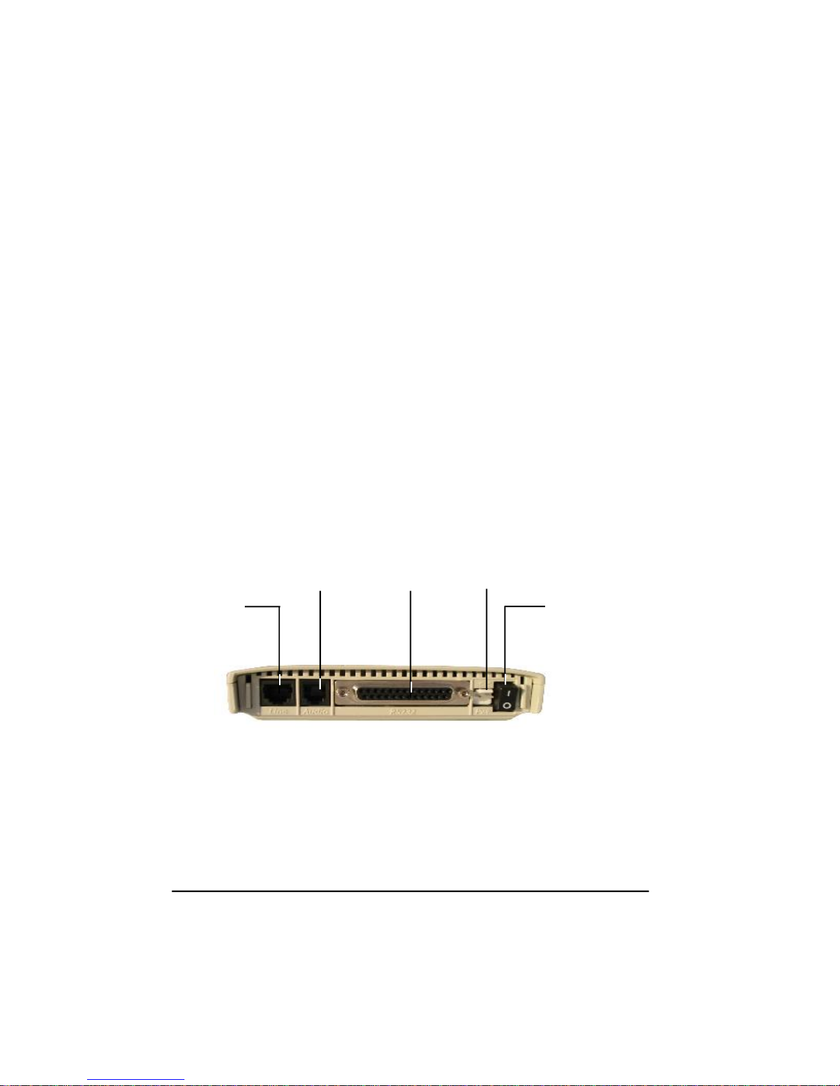
Hardware Overview
Back View
The following figure shows the back view of the modem. Starting from the left side, this
view shows:
• A line jack for connecting the modem to the communications line.
• An audio jack for leased-line operation.
• A female, 25-pin RS-232 connector for connecting a standard DTE (RTU).
• A power connector.
• An ON/OFF switch.
Telco/Dial Line
Telephone
Set
DTE RS232
Connector
Low Voltage
Power Input
ON/OFF
Front View
The front view of the modem has 10 LED status indicators. For more information about
these indicators, see “Modem LED Display” on page 14 and “Front Panel Mode LEDs”
on page 15.
Option DIP Switch
(see page 62)
LEDs (see page 15)
Mode Switch for
Dumb Operation
(see page 56)
Data/Talk Switch
(see page 58)
Page 8
Page 9

Installation
Installation Summary
The modem installation involves the following steps:
1. Finding a suitable location for the modem. See the section below.
2. Making the necessary modem connections. See page 12.
3. Installing the modem driver. See page 13.
Finding a Suitable Location
The location you select for your modem should provide easy access to the back panel
communications interfaces and provide a clear view of the front panel LED indicators.
Page 9
Page 10
Connecting the Cables
1. Turn off your computer.
2. Plug the data cable's male end (pins showing) into the connector marked RS232 at the back
of your Modem and then plug the female end (no pins showing) of the same cable into the
COM port at the back of your computer.
3. Your computer's COM port could be 9 pins or 25 pins. Use the appropriate connector on
the cable suppled to conntect your Modem to your Serial port.
4. Plug the telephone cable into the connector marked LINE at the back of your Modem and
the other end of the cable into your telephone wall socket.
+
Your Modem has a Telephone Set connector to allow 4-wire leased-line operation.
Refer to the section on Leased Line Operations for details on this feature.
5. Plug the power cable pin into the POWER connector at the back of your Modem and plug
the power supply into a suitable power point.
6. Use the ON/OFF switch to turn on your Modem. Then check that some of the Modem
lights illuminate.
7. Restart your computer.
8. Now you need to install your Modem's Driver. Which operating system is your computer
running? Read the next section for driver installation instructions.
Telco/Dial Line
Telephone
Set
DTE RS232
Connector
Page 10
Low Voltage
Power Input
ON/OFF
Page 11

Installation
Driver Installation
Windows 2000
1. Windows will detect the modem automatically. Please insert the supplied CD and click
"Next".
2. Select "Search for a suitable driver for my device [recommended]", and then click "Next".
3. Select "Specify a location" and click "Next".
4. Enter the driver location "D:\" where D:\ is the letter of your CD ROM drive and click on
"OK".
5. Windows will find the correct driver for your modem. Click "Next" to continue.
6. When the "Digital Signature Not Found" screen appears, click "Yes" to continue.
7. Click "Finish" to end this procedure.
Windows ME
1. Please insert the supplied CD and, when the "Found New Hardware Wizard" recognises the
new Modem, select "Specify the location of the driver [Advanced]" and click "Next" to
search for the driver.
2. Select "Search for the best driver in these locations" and choose "Specify a location".
Type in "D:\" (where D:\ is the letter of your CD ROM drive) and click "Next" to continue.
3. Click "Next" to start the installation.
4. Click "Finish" to end this installation procedure.
Windows 98
1. Please insert the driver CD supplied and, when the "Found New Hardware Wizard"
recognises the new Modem, click Next to search for the driver.
2. Select the "Search for the best driver your device. [Recommended]" and click "Next" to
continue.
3. Select the "Specify a location" option and type "D:\" where D:\ is the letter of your CD
ROM drive. Click "Next" to start the search for your driver.
4. Click "Next" to start the installation.
5. Click "Finish".
Page 11
Page 12

Modem LED Display
+
When your modem is using V.90, the Front Panel Mode LEDs will display the speed
closest to the K56flex speed.
Transmit Data (TXD)
LED will flash when the modem is sending data.
Receive Data (RXD)
LED will flash when the modem is transferring data from the remote to the local computer.
Off-Hook
LED will glow when the modem is on-line; ie. dialling or answering
Carrier Detect
LED will glow when the modem detects a valid carrier signal from a remote modem.
Auto-Answer
LED will glow to indicate auto-answering operation. If the modem is performing a test, the LED
will flash until the test is completed or cancelled.
Terminal Ready
LED indicates the ‘Data Terminal Ready’ (DTR) signal is asserted.
Page 12
Page 13

Installation
Front Panel Mode LEDs
Line Modulation One Two Three Four
K56flex 56000 bps Z M Z M m m
K56flex 54000 bps Z M Z M l m
K56flex 52000 bps Z M m m m
K56flex 50000 bps Z M l m m
K56flex 48000 bps Z M m l m
K56flex 46000 bps Z M l l m
K56flex 44000 bps m m m m
K56flex 42000 bps l m m m
K56flex 40000 bps m l m m
K56flex 38000 bps l l m m
K56flex 36000 bps Z M Z M m m
K56flex 34000 bps l m l m
K56flex 32000 bps m l l m
K56flex 30000 bps l l l m
33600 bps ZF ZF m l
31200 bps ZF ZF l l
28800 bps ZF m m l
26400 bps ZF m l l
24000 bps ZF l l l
21600 bps Z M m m l
19200 bps Z M l m l
16800 bps Z M m l l
14400 bps l l l l
12000 bps l l m l
9600 bps m l m l
7200 bps m l l l
4800 bps l m m l
2400 bps ZS m m l
1200 bps ZS m l l
1200/75 bps ZS l m l
300 bps ZS l l l
Fax 14400 bps m ZS ZS l
Fax 9600 bps m m ZS l
Fax 7200 bps m l ZS l
Fax 4800 bps l m ZS l
Fax 2400 bps l l ZS l
LED: l = Off m = On
Flashing:ZS = Slow, ZM = Med, ZF = Fast
Page 13
Page 14

The AT Commands
The AT commands are a group of special commands recognised by your modem. These
commands derive their name from the letters AT, which are used to prefix commands. Before
continuing:
• Run your communications software and enter local mode (or terminal mode) at 38,400 bps
Refer to your communication software manual for details.
The Attention Code
An AT (sometimes known as the ATtention code) usually precedes all commands being sent to
the modem. It is used to gain the modem’s attention, informing it that you are about to send a
command. For example:
• Type the command: ATI9 <E>
Your modem’s firmware identity message will appear on your computer screen. If you type I9
only, your modem will not respond. If you type AT19, your modem will report an ERROR.
You may enter the attention code in all upper case, or all lower case letters, such as: AT or at
Multiple Commands
You may place multiple modem commands after an AT provided the total number of characters
does not exceed 80. For example, a valid command to display the modem’s firmware identity
twice is:
• Type in the command: ATI9I9 <E>
An AT is not required in front of the second I9 command. You only need one attention code for
each command line. To make this command more readable, you can add spaces between the two
commands:
• Type in the command: AT I9 I9 <E>
The modem will execute the command as if the spaces are not there.
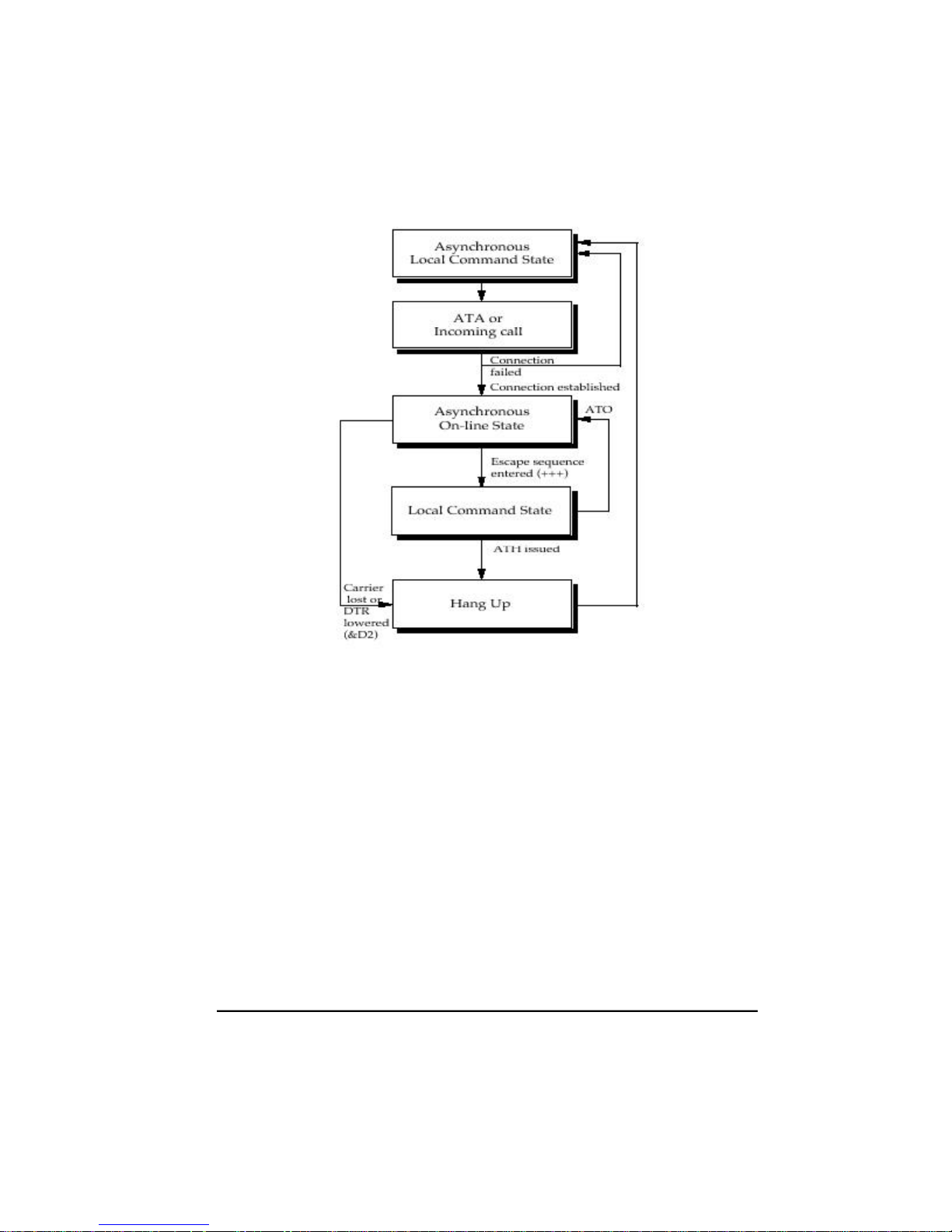
The Escape Sequence
When you issue commands to the modem all dialogue is occurring between your computer and
the modem. This situation is known as local command state.
When you connect to a remote system, dialogue will be occurring between your computer and
the remote system. This is known as on-line state. Because the modem assumes, after it enters
on-line state, all the data you send it is to be sent on to the remote modem, it ignores any AT
commands you give it while in on-line state.
To force the modem to return to local command state, enter an escapesequence. An escape
sequence consists of a one second delay, three + characters typed rapidly and another one
second delay. For example:
Page 14
Page 15

AT Commands
• Type: AT&T1 <E>
The modem will enter on-line state (this command actually causes the modem to enter test
mode, but is equivalent to entering on-line state).
Now try to view the modem’s firmware identity code:
• Type: ATI9 <E>
Your command will be ignored. This is because the modem assumes you are typing characters to
be sent to a remote system.
Now enter an escape sequence. Do not type any characters for one second, type +++ rapidly
and wait another full second. The modem will respond with an OK message to indicate it has
returned to local command state. You will be able to view the modem’s firmware identity.
Before continuing:
• Type: AT&T0 <E>
This command is used to halt the test.
The Repeat Command
The repeat command is used to re-execute the last command issued to the modem. Issue the
ATI9 command and the modem’s firmware identity code will be displayed on the screen.
• Type: A/
The identity code will appear again.
You don’t have to enter AT before the repeat command. You also do not have to press the
ENTER key. This is the only modem command which does not require you to enter AT before
it, and one of the few commands which does not require you to press the ENTER key. The A/
command is intended primarily for re-dialling a telephone number that was previously engaged.
The Help Command
Your modem will display information about the AT commands it supports if you type a
question mark (?) in your AT command.
For example:
• Type: AT? <E>
Your modem will display a list of all the commands it supports.
• Type: AT?DTR <E>
Your modem will display a summary of commands involving DTR.
• Type: AT?\N3%C2&D2 <E>
Your modem will display summaries of the \N, %C and &D commands.
Page 15
Page 16

Response Codes
Your modem is capable of telling you, with on screen messages, what it is doing. These messages
are known response codes or result codes, and you will see them from time to time.
For example:
After a command is successfully executed, the response is: OK After a connection is established,
the response is: CONNECT A complete list of Response Codes can be found in Appendix A.
Dialling
The AT commands may be used to initiate dialling with the modem. Your modem does not
require a telephone handset to be connected to it in order to dial.
The D (Dial) command is used to initiate a telephone call. The most basic form of the D
command is:
ATD number where the number is the telephone number you are dialling.
Having set your communications software for 38,400 bps operation:
• Type: ATD01234 <E>
Your modem will begin to dial.
+
If your modem receives a character from your computer while dialling is being
performed, it will immediately hang up, send a NO CARRIER response message to
the computer and return to local command state. After a few seconds the message
CONNECT will appear on the screen.
If a NO CARRIER message appears, then your modem has not been able to make a connection.
Check your communications software is set for 38,400 bps operation and your modem is
correctly connected to your computer and the telephone line. You may use the A/ command to
redial.
To hang up the modem, enter an escape sequence (+++). The modem will respond with an OK
message.
• Type: ATH <E>
The modem will hang up.
+
Your computer must assert the DTR signal before dialling can start. Usually, this
is done by your communications software. If the DTR signal is lowered at any
stage of communications, after the &D2 command has been issued, the modem
will hang up and return to local command state. Interpretation of the DTR signal
may be changed with the &D command.
Page 16
Page 17

AT Commands
Dial Modifiers
Dial modifiers are characters than can be included in a phone number to make the modem
perform special tasks while dialling. For example, not all modem users will be using a dedicated
telephone line. Some users will have their modems connected to PABXs. To allow users of
PABXs to operate their modems successfully, dial modifiers are supported on the modem.
Most PABXs require you to dial 0 or 9 (in order to obtain an outside line) and wait for a dial
tone before dialling the actual phone number. Using dial modifiers, you can successfully dial the
phone number 12345 through a PABX using the command:
ATD0,12345
The , (comma) dial modifier causes the modem to pause for a short time after dialling 0. This
allows most PABXs sufficient time to obtain a line before dialling.
The factory default delay for the , modifier is two seconds. You may change the length of this
delay if necessary. Its length is determined by the value in S Register 8.
Another method of making the modem wait for a dial tone is to include the W dial modifier. The
W modifier causes the modem to examine the phone line to ensure a dial tone has been applied
before dialling starts:
ATD0W12345
If the modem cannot detect a dial tone within the time specified by S Register 7, the modem will
return to local command state and send a NO DIALTONE message to the computer (if either the
X2, X4, or X5 commands have been issued).
Due to differences with some older telephone exchanges, dial tone detection may not be possible
with your modem. Your modem will only recognise dial tones between 200 Hz and 600 Hz.
If your telephone line supports tone dialling then a useful dial modifier is the T modifier.
Inserting a T modifier before the number you are dialling causes the modem to tone dial that
number. For example:
ATDT12345
This will cause the modem to dial the phone number 12345.
These modifiers may be placed at any point in the number you are dialling and they may be
intermingled in the same number. More information about dial modifiers can be found in the
Command Descriptions chapter of this guide.
Page 17
Page 18

Hanging Up
The H command is used to hang up the modem. After you have finished communicating with
another computer you must hang up your modem. Similarly, you must hang up the phone after
calling another person. If you don’t, no one will be able to call you and you may even be charged
for the length of time the phone was off the hook.
To hang up your modem:
• Type: ATH <E>
The modem will return an OK response message.
Stored Number Dialling
Your modem has the ability to store phone numbers which may be dialed at a later time. This is
similar to ‘abbreviated dialling’, which may be supported by your telephone.
To store a phone number use the &Z command. For example:
• Type: AT&Z1=012345 <E>
The phone number 012345 will be stored as phone number one. The S dial modifier is used to
dial a phone number that has been stored in your modem:
• Type: ATDS=1 <E>
The modem will dial stored phone number one.
+
Do not include an AT, D command, or S dial modifier in the stored phone number.
If synchronous mode 2 is being used, the ; (semi-colon) dial modifier should not
be included.
Answering Calls
As well as dialling other modems, your modem can answer calls made to it by other modems.
Page 18
Page 19
AT Commands
Your modem is pre-configured to automatically answer any incoming call, provided it is
switched on, is in local command state, DTR is high and is not performing a test. If you receive a
call on the phone line the modem is connected to, it will answer the call and attempt to connect
to the calling modem.
S Register 0 contains the number of rings the modem will wait before answering a call. If a value
of 4 is placed in S Register 0, the modem will answer an incoming call immediately after the
fourth ring. If a 0 value is placed in S Register 0, the modem will not answer an incoming call.
The communications standard used by the modem in its attempt to connect with a calling
modem is determined by the B command.
If the phone does ring, and verbal response codes are selected (ATV1), the modem will issue
RING messages until the number of rings stored in S Register 0 is reached. The modem will then
go on line, transmit an answer tone, and attempt to connect to the calling modem using the
communications standard selected by the B command.
By default the modem is set to B0. B0 is the auto range setting. This should connect to virtually
all communications standards and normally you do not have to alter this. As soon as a
connection is established, the modem will send a CONNECT message to your computer and
enter on-line state in answer mode.
Page 19
Page 20

Selecting Speeds
The following section describes how to select line and terminal speeds for your modem.
Terminal Speeds
Your modem has the ability to communicate with your computer at various speeds. The modem
offers two speed modes: variable speed mode and constant speed mode.
Constant speed mode forces your modem to maintain the terminal speed that was selected when
you dialed another modem, even if the connection speed made with the other modem does not
match the terminal speed of your modem and computer.
For example, if your modem connected to another modem at 2400 bps and its terminal speed is
9600 bps, the modem will maintain its terminal speed at 9600 bps. Because of this, you must
select flow control between the modem and your computer. To select constant speed mode:
• Type: AT\N0 <E>
For more details on constant speed mode and flow controls, see the Command Descriptions
chapter for a discussion of the \N, B and &K commands. + Some computers cannot cope with
receiving data at speeds above 19,200 bps. If you wish to run at high speeds, you should install
a COM port that has a 16550 chip in place of your regular COM port. The 16550 chip allows
your computer to accept data at very high speeds when used with suitable drivers and software.
Variable speed mode allows your modem to automatically adjust its terminal speed to match the
line speed. For example, if your modem connects to another modem at 4800 bps and its terminal
speed is 9600 bps, the modem will automatically change its terminal speed to 4800 bps (and,
thus, you or your software would have to change the speed of your computer to 4800 bps).
If you have variable speed mode and B0, B1, B2 or B9 selected, the modem will attempt to
connect at a speed to match the terminal speed.
At 300 bps, select B0 or B2 for V.21, or B1 for Bell 103. At 1200 bps, select B0 for V.23, B1 for
Bell 212A, or B2 for V.22.
Variable speed mode may be selected by:
• Type: AT\N1 <E>
For more details about the variable speed mode, see the \N and B commands in the Command
Descriptions chapter of this guide.
Page 20
Page 21

AT Commands
Setting Terminal Speeds
Your modem can sense the terminal speed of the computer and automatically change its terminal
speed to match. This is known as ‘auto bauding’, and is done each time an AT command is
issued to the modem.
Your modem can auto baud at 300 bps through 9600 bps, 14,400 bps, 19,200 bps, 38,400 bps,
57,600 bps and 115,200 bps.
The R command may also be used to disable autobauding and lock the terminal speed. Refer to
the R command for available speeds.
Line Speeds
Connection speeds higher than 33600bps can only be obtained by calling an Internet Service
Provider (ISP) or Central Site which supports the Rockwell K56flex™ protocol. The speeds at
which you will be able to connect also depend on the quality of the telephone line used when
making the connection.
The B command determines the speed at which your modem connects to another modem. The
listed B commands are provided by your modem.
In most cases you should select B0, as this setting attempts to connect at any speed supported
by the modem.
V.90 & V.34 Typical Settings
Here are some example settings that may be relevant to the way in which you wish to operate
your modem.
Example 1 - Dialling or answering other modems at the highest speed.
B Command Setting: B0
Terminal Speed: 115,200 bps
Flow Control: On (&K3 for RTS/CTS flow control)
Use this arrangement when dialling online information services or bulletin boards. With these
settings, you modem will attempt to connect at any speed from 56,000 bps to 1200 bps. These
are the default settings of your modem.
If you wish your modem to answer incoming calls, use these settings. This will allow your
modem to connect at any speed between 56,000 bps and 300 bps. If you are using a software
program that controls the answering of your modem (as some bulletin board systems do) you
may need to issue an ATS0=0 command to disable auto-answering, otherwise issue ATS0=2 to
make the modem answer calls after two rings (the default setting).
Page 21
Page 22

Example 2 - Dialling other modems at 19,200 bps (V.34 or V.FC)
B Command Setting: B18
Terminal Speed: 57,600 bps
Flow Control: On (&K3 for RTS/CTS flow control)
You may use this arrangement when dialling online information services or bulletin boards. With
these settings, you modem will attempt to connect at 19,200 bps, but may change the line speed
if the quality of the telephone line does not support this speed.
Example 3 - Dialling information services at 1200 bps (or V.22)
B Command Setting: B6
Terminal Speed: 38400 bps
Flow Control: On (&K3 for RTS/CTS flow control)
Some information services do not provide connections higher than 1200 bps; these settings allow
you to connect to such services. Problems may also occur if error correction is switched on; if
the information service does not support V.42 or MNP, issue the \N0 command before dialling.
V.32bis Modem Typical Settings
Here are some example settings that may be relevant to the way in which you wish to operate
your modem with V.32bis.
Example 1 - Dialling other modems at the highest possible V.32bis speed
B Command Setting: B0
Terminal Speed: 38,400 bps
Flow Control: On (&K3 for RTS/CTS flow control)
Use this arrangement when dialling online information services or bulletin boards. With these
settings, your modem will attempt to connect at any speed from 14,400 bps to 1200 bps. These
are the default settings of your modem.
Example 2 - Dialling other modems at 14,400 bps (or V.32bis)
B Command Setting: B15
Terminal Speed: 38,400 bps
Flow Control: On (&K3 for RTS/CTS flow control)
You may use this arrangement when dialling online information services or bulletin boards. With
these settings, your modem will attempt to connect at any speed from 14,400 bps to 1200 bps.
Because V.32bis operation is not suitable on poor-quality telephone lines, we recommend you
use these settings with caution; if you have trouble connecting to another modem using V.32bis,
revert to the settings shown in Example 1.
Page 22
Page 23

AT Commands
Example 3 - Answering incoming calls
B Command Setting: B9
Terminal Speed: 38,400 bps
Flow Control: On (&K3 for RTS/CTS flow control)
If you wish your modem to answer incoming calls, use these settings. This will allow your
modem to connect at any speed between 14,400 bps and 300 bps. If you are using a software
program that controls the answering of your modem (as some bulletin board systems do) you
may need to issue an ATS0=0 command to disable auto-answering, otherwise issue ATS0=2 to
make the modem answer calls after two rings (the default setting).
Page 23
Page 24

Flow Control
Your modem supports RTS/CTS, XON/XOFF and Transparent XON/OFF flow control. Flow
control ensures that data is not lost between your computer and your modem. Flow control will
be ignored when your modem is configured for variable speed mode (AT\N1) or is in local
command state.
RTS/CTS Flow Control
RTS/CTS flow control takes place when the modem and computer manipulate the CTS (Clear
To Send) and RTS (Request To Send) signals to stop and start data flow. This form of flow
control is recommended if supported by your computer and communications software, as it
does not interfere with file transfer protocols.
+
In order for flow control to operate correctly between your computer and the
modem, the appropriate form of flow control must be selected with your
communications software. See your communications software manual for details.
You must also have a modem cable that connects the RTS and CTS signals of your
modem to your computer.
RTS/CTS flow control is selected with the &K3 command.
XON/XOFF Flow Control
XON/XOFF flow control takes place when the modem and communications software transmit
XON and XOFF characters to start and stop data flow. This form of flow control is only
recommended when your computer or communications software does not support RTS/CTS
flow control. The ASCII values of the XON/XOFF characters are 17 (DC1) and 19 (DC3)
respectively.
XON/XOFF flow control is selected with the &K4 command.
+
XON/XOFF flow control should not be used with the XModem, YModem or
SEAlink file transfer protocols.
Transparent XON/XOFF Flow Control
Transparent XON/XOFF flow control is identical to normal XON/XOFF flow control except
the XON and XOFF characters which are part of the normal data stream are encoded to allow
flow control with file transfer protocols such as XModem. The ASCII values of the XON and
XOFF characters are 17 (DC1) and 19 (DC3) respectively.
Page 24
Page 25

AT Commands
Transparent XON/XOFF flow control is selected by issuing the &K5 command.
Failsafe Flow Control
Failsafe flow control is designed specifically for UNIX computers running the UUCP file
transfer protocol. This form of flow control only affects data being transmitted from the
computer to the modem.
When the modem’s data buffer approaches maximum capacity, the modem will lower the CTS
signal. If the computer does not pause the transmission of data within a few character durations
of CTS going low, the modem will send an XOFF to the computer.
When the modem is ready to accept more data from the computer it will assess CTS. If an
XOFF was sent to pause transmission, the modem will also send an XON character.
+
Failsafe flow control only affects data being transmitted from the computer to the
modem. Flow control is not supported for data being transmitted by the modem to
the computer. Failsafe flow control is selected by issuing the &K9 command.
The Inactivity Timer
Your modem supports an inactivity timer. When your modem is on line, if it does not
communicate with either the remote modem or your computer for a specified length of time, it
will hang up and return to local command state.
The AT\T command specifies the number of minutes the modem stays on line when no activity
is occurring. The timer may be set from 1 to 255 minutes.
For example:
AT\T5
This allows the modem to be inactive in on-line state for five minutes before hanging up the
default time is 0 minutes the timer is disabled. The inactivity timer is only available when MNP
or constant speed mode is selected. It is ignored in variable speed mode.
The Command Timer
If you do not complete an AT command within 60 seconds (that is, type the command and press
ENTER), the command will be discarded and an error message will appear. The length of time is
controlled by S Register 69 and can be turned off by setting S Register 69 to 0.
Page 25
Page 26

Configuring the Modem
Your modem allows you to tailor its operating parameters to suit your own particular
requirements.
The modem uses S Registers to alter the configuration profile. Each S Register contains a decimal
value to represent a time delay, an ASCII character or the number of times the phone should ring
before the modem answers it (the interpretation of each value differs with each S Register).
The modem allows you to save the contents of the S Registers and certain communication
settings under a profile number (0-3) in non-volatile memory (&Wn). This means the entire
configuration profile will be retained after you have switched your modem off.
The modem also has factory default settings stored internally, allowing you to change the
communication settings and S Register values and then recall the configuration profile stored in
your modem when you originally purchased it.
The factory defaults have been selected so most users will be able to make immediate use of
their modem, without the need to change any S Register values.
You may restore your modem to its factory defaults at any time:
• Type: AT&F.
There is no need to press ENTER with this command.
Viewing the Current Configuration
The &V command allows you to view the current configuration of your modem. When you issue
the &V command, your modem sends a list of the current AT command and S Register settings
to your computer.
Page 26
Page 27

AT Commands
Error Correction
Error Correction Protocols
This section examines the error correction and data compression features of your modem. The
modem offers both V.42 (LAP-M) and MNP® (Microcom Networking Protocol™) error
correction protocols. These protocols allow data errors to be detected by the receiving modem,
provide flow control between remote systems and improve the overall throughput of data
transfers.
Your modem also supports V.42bis and MNP5 data compression. V.42bis is a high performance
data compression enabling you to speed up, theoretically by four times, data throughput on
some types of data. MNP5 allows you to speed up data throughput by up to two times on
some types of data.
+
Aust Modems: Before dialling into an AUSTPAC V.22 or V.22bis
service, error correction must be disabled using the \N0 command.
Two types of error correction protocols are offered by your modem; V.42 (or LAP-M) and
MNP.
+
Error correction protocols are not available when a V.23 connection is
established.
V.42 is an international standard for error correction between modems. V.42 ensures any errors
introduced into your data by telephone line noise is automatically corrected before it is received
by your computer. Because V.42 is a ITU standard, it has become very popular in modems all
over the world.
V.42 also supports a fallback mode to MNP, in order to remain compatible with modems
introduced prior to V.42.
Before V.42 existed, MNP was the de-facto standard for modem error correction. MNP classes
2-4 are supported by your modem for error-correction (an additional class of MNP is supported
for data compression). Because MNP is a far less complex error correction protocol than V.42, it
out-performs V.42.
The section titled “Which Error Correction Do I Use?” provides more information about the
performance and compatibility merits of V.42 and MNP.
The \N command is used to select the type of error correction used by your modem.
Page 27
Page 28

Data Compression
Two forms of data compression are supported by your modem; V.42bis and MNP 5. V.42bis is
based on the Lempel-Ziv compression technique (similar to the techniques used by PC
compression programs) and can work with both V.42 and MNP. V.42bis is very good at
compressing data that has repetitions of sequences of characters. For example, in an English
sentence there are usually repetitions of ‘ions’ or ‘ings’ or ‘ere’; V.42bis works by creating a
library of these repetitions and substituting small symbols for them. V.42bis is also able to
switch off data compression if the type of data being sent is unsuitable for compression.
MNP 5 is MNP’s stable-mate; it uses ‘run length encoding’ and a variation of the Huffman
compression technique. It can double your data throughput on some types of data and MNP 5
works best when there are lots of characters repeated in sequence or a particular character
repeated. For example, if you have a file which contained 50 zero characters in sequence MNP 5
will do a good job of compressing them (in some instances, better than V.42bis) – this is run
length encoding. Or, if you had a text file where every second character was an ‘i’ and the other
characters were random, MNP 5 would again outperform V.42bis (in this instance, Huffman
coding provides superior compression). However, MNP 5 does not employ V.42bis’ automatic
switching techniques.
If the data you are sending is not suitable for compression (for example, an application file or a
graphics file), it can actually take longer to send than if data compression was not being used.
For this reason, it is best to use V.42bis whenever possible. If the modem you connect to does
not support V.42bis, it is best not to use MNP 5 unless you are only transferring plain text
information. If possible, use one of the many popular data compression programs available for
computers to compress applications, graphics and other non-text files.
The %C command is used to select the type of data correction used by your modem.
Reliable Mode
Reliable mode allows the modem to use error correction to connect to another modem. If the
modem you attempt to connect to does not support a compatible method of error correction,
your modem will hang up and return a NO CARRIER message.
Use \N6 to select V.42/MNP reliable mode, \N4 to select V.42-only reliable mode or \N2 to select
MNP-only reliable mode.
Auto-Reliable Mode
Auto-reliable mode allows your modem to use V.42 or MNP if the remote modem also supports
these. If the remote modem does not support a compatible type of error correction, your modem
will fallback to either constant speed or variable speed mode.
+
The \J command determines whether your modem falls back to constant speed or
Page 28
Page 29

AT Commands
variable speed mode.
\N3 selects V.42/MNP auto-reliable mode and \N5 selects V.42-only autoreliable mode.
Your modem supports special CONNECT messages for connections made with either reliable or
auto-reliable modes. When the AT\V1 command is issued and your modem connects in either
reliable or auto-reliable mode, a response message will be sent to your computer.
When the AT\V0 command is issued (default), your modem will generate standard CONNECT
messages for both normal and error-corrected connections. If the X0 command has been issued,
the CONNECT/REL will be the only ‘error correction’ response code generated, regardless of
the connection speed.
+
Issue the %U1 command if you want your modem to issue CONNECT/ LAP-M
response codes when a V.42 connection is established. The \V8 command will
display details of the error correction and data compression negotiated with the
remote modem. This information is displayed immediately before the CONNECT
message.
The \V9 command will display details of the error correction and data compression negotiated
with the remote modem as well as diagnostic information. This information is displayed
immediately before the CONNECT message.
Improving Performance with MNP 10
MNP 10 is neither an error correction or data compression technique. MNP 10 works in
conjunction with error correction and data compression to improve the performance of your
modem when operating with poor or varying quality telephone lines (as sometimes found with
overseas or cellular telephone connections).
With MNP 10 operating, your modem can automatically resize the MNP packets, depending
upon the line quality. When an MNP connection is established, data is transferred in small
‘chunks’ known as packets. When the line quality drops, MNP 10 reduces the size of packets
being transferred in order to maintain data throughput. MNP 10 will increase the packet size to
take advantage of improved line quality.
If the line quality becomes very good or very bad, MNP 10 can automatically step between line
speeds. MNP 10 attempts to use the highest speed applicable to the quality of the telephone
connection. If the telephone line quality drops while you are connected to another MNP 10
modem, thus introducing errors into your data, and the smallest packet size is being used, the
modems will ‘step-down’ in speed until the error rate become acceptable.
Similarly, if the line quality improves and the modems are using the largest packet sizes, the
modems will ‘step-up’ in speed until the best compromise of error rate and line speed is found.
MNP 10 will also make multiple attempts at establishing an error-corrected connection to
another modem (more so than MNP 2-4). This gives you a better chance of making a connection
Page 29
Page 30

when operating with poor line quality.
If the telephone line drops out, MNP 10 will attempt to reconnect up to the maximum time
permitted by your country’s telecommunications rules. Thus, if there is a short line drop-out,
MNP 10 will provide minimal interruption whereas other modems will disconnect entirely.
MNP is the only type of error correction allowed with MNP 10 and is only available when
connected to another modem that supports MNP 10. The #K command is used to select MNP
10.
Speed Changes
Although MNP 10 is able to cope with bad telephone connections, your modem must be able to
first make a connection with another modem before it can make use of MNP 10. For this reason
you may wish to use the AT%H1 command to force your modem to connect at 1200 bps and
then ‘upshift’. Most telephone lines will cope with V.32 or V.32bis connections, however
connecting at 1200 bps will ensure you make a connection. You may also use the J dial modifier
to force your modem to make the initial MNP 10 connection at 1200 bps.
When MNP 10 changes line speed (either up or down) there will be a slight interruption to your
communications. For this reason you should always use flow control to ensure data is not lost
when MNP 10 changes line speed.
If you wish to establish the connection prior to MNP 10 upshifting or downshifting, issue the
%H9 command. This allows you to use the connection before MNP 10 attempts to change the
connection speed.
Cellular Modem Users
If you are making modem calls with a cellular phone, issue the AT#K2 command. This tells
MNP 10 to try even harder to maintain the connection if your cellular call momentarily drops
out.
With such a choice, you may be wondering which combination you should be using. The table
below shows the relative performance of each combination of error connection and data
compression.
If you are connecting to various makes and models of modems, V.42/V.42bis auto-reliable mode
is probably the best alternative (AT\N3%C2). V.42/ V.42bis auto-reliable mode will also connect
to another modem that supports MNP with V.42bis data compression. For overseas or cellular
connections, use MNP 10 if possible (AT\N3%C2#K1).
Page 30
Page 31

AT Commands
Increasing Data Throughput with Error Correction & Data
Compression
Data throughput refers to the amount of data being transferred. Error correction and data
compression allow you to increase data throughput in comparison to if error correction and data
compression were not selected. To allow error correction and data compression to operate with
the highest possible throughput, the terminal speed of your modem (the speed it communicates
with your computer) must be higher than the line speed (the speed it communicates with the
remote modem).
The best way to operate with error correction and data compression is to set your modem for a
constant speed of 57,600 bps, 115,200 bps or higher (set the terminal speed of your computer
to 57,600 bps, 115,200 bps or higher and issue the command AT\N3 to the modem) with flow
control. RTS/CTS flow control is the preferred form of flow control. Your communications
software must also be set to use the same type of flow control.
+
Some computers cannot cope with receiving data at speeds above 19,200 bps. If
you wish to run at high speeds, you should install a COM port that has a 16550
chip in place of your regular COM port. The 16550 chip allows your computer to
accept data at very high speeds.
Page 31
Page 32

Security & Encryption
Your modem has many sophisticated security features. Your modem limits caller access by
means of user names and passwords. User names and passwords are stored in the modem’s non-
volatile memory. With each user name and password a modem command of up to 30 characters
may be specified. This allows the implementation of callback to users.
Callback is where the modem rings a specified phone number. Even if an unauthorised caller
manages to break the modem’s security, that caller must be connected to the phone number
specified in the remote modem’s database. Also discussed in this section is the topic of DES
(Data Encryption Standard) encryption, which allows you to encrypt data being passed to a
remote modem.
The Security Menu
All additions and changes to your modem’s user and password lists are performed through the
Security Menu. This menu is displayed when you use the #S command.
• Type: AT#S <E>
A prompt will appear: Enter Security Password:
When you first receive your modem, all passwords will be set as a single Carriage Return
(ENTER).
• Press the ENTER key
The Security Menu will be displayed.
Enter Security Function :...
Entering a Security Password
You may choose to have a dedicated security password, thus changing the password assigned for
the first security user. To enter a new security password:
• Select Option 8 from the Security Menu <E>
You will be prompted to enter a new security password. Your modem is case insensitive. Up
to 8 characters may be used, including spaces.
When you enter your password, each character will appear on the screen as a # character.
• Type in your new password <E>
You will be prompted to re-enter the new security password.
• Type in your new password again <E>
Your new password will be stored in your modem’s non-volatile memory.
Page 32
Page 33

AT Commands
Adding and Changing Users
Your modem allows you to add new users and change existing users. Selecting option 2 on the
Security Menu will result in a prompt: Enter Name:
To add a new user:
• Type in the name of the new user <E>
User names must not be longer than 30 characters. They are NOT case sensitive.
To change an existing user:
• Type in the name of the user you wish to change <E>
You will be prompted to enter a new name.
• Type in the new name <E>
• If the user is found you will be given the option to change the password, delete the user or
zero their access counters.
If you are adding a new user or changing a user, you will be prompted for a new Password
(maximum characters = 15).
You then will be prompted for ‘Options’ after the password has been entered.
You may key S or E or both, if you do not want either option key ENTER.
q S Specifies that the user is a supervisor and has full remote access rights to the remote
modem.
• If you key **** you will be able to issue almost all AT commands on the remote modem and
access the full security database if you have the global security password. (See remote
access)
q E Your user password does not expire.
• This would be for automated systems that cannot respond to prompts to enter a new
password when it expires The modem will now prompt you to enter a modem command.
Modem commands consist of up to 30 characters and may include spaces. When you enter a
new command, the previous command will be overwritten.
+
Do not include an Attention Code (AT) with your command. Your modem
automatically places an AT at the start of this command when it is executed.
If you do not want to specify a modem command or want to leave the current command as it
is:
• Press ENTER
If you want to remove the existing command but do not wish to replace it with another
command:
• Press the Spacebar <E>
See details on Callback Security later in this section for more information about using
commands with your user names.
Page 33
Page 34

If you do not enter a command you will be given the option of entering a SuperSecure DES
Key for the user. To use this feature refer to the ‘SuperSecure Advanced Security Mode’ or
else press ENTER to go on to the next user.
Removing Users
Your modem allows you to remove individual users or all the users currently stored in your
modem. To remove an individual user:
• Select option 2 from the Security Menu You will be prompted to enter a new user name.
• Type in the name of the user you wish to delete <E>
If the user is found, select the ‘D’ option to delete.
To delete all the users stored in your modem:
• Select option 3 from the Security Menu
You will be prompted to confirm that you wish to remove all user names, passwords and
commands
• Press Y <E>
Listing Existing Users
To list all user names, and commands.
• Select option 1 from the Security Menu <E>
Your modem will list the user names.
Passwords are never displayed.
+
Your computer must be capable of displaying at least 80 characters per line for
the user list to be displayed in its correct format.
The Access Record
Selecting option 4 and option 5 from the Security Menu allows you to view and change the
access records. Your modem keeps a tally of the number of successful (granted) and unsuccessful
(denied) attempts to connect to your modem using each user name.
Your modem allows every caller three attempts to enter the correct user name and password. If
the caller cannot correctly enter the password, a record is made by your modem that an
unsuccessful attempt has been made to use that particular user name.
If the number of unsuccessful calls for any user name reaches 255, that user name will be locked
and callers will no longer be able to use it, even if the correct password is used. You will not be
able to use that particular user name until the access record for all users has been reset.
If, however, the caller does correctly enter the password, your modem records that a successful
Page 34
Page 35

AT Commands
attempt was made to connect with that user name.
You should regularly check the number of successful and unsuccessful attempts to connect to
your modem.
• Select option 4 to view the access record <E>
An unusually high number of unsuccessful attempts to connect with a particular user name may
indicate someone is trying to violate your modem’s security.
Over a period of many months one of the security users may legitimately accumulate 255 errors,
in which case, your modem will automatically lock that user. If this occurs, select option 2, enter
the user’s name and select the Z option to clear his access record.
Each attempted access with an unknown name increments the ‘Invalid Usernames Received’
count at the top of the list.
Enabling Modem Security
Selecting option 6 or option 7 allows you to disable or enable your modem’s security mode.
With security mode enabled, whenever your modem answers an incoming call it will demand the
caller enter a user name and password — the following message will appear on the caller’s
computer screen:
Enter Name:
If only one of the modems is configured to use error correction, there will be a slight delay
between the time the modems connect and when the caller is asked to enter his user name.
When the caller enters his name all characters will be displayed as # characters.
The caller is allowed three attempts to correctly enter his name. Your modem is not case
sensitive to user names. If the caller enters a valid user name, your modem will ask the caller to
enter the password associated with that user name.
Enter Password:
If the caller enters his password correctly, your modem will send the message ACCESS
GRANTED and the caller will have access to the computer connected to your modem.
If the caller cannot, within three attempts, enter the correct user name and password, your
modem will send the message ACCESS DENIED and will hang up.
Quitting the Menu
The Quit Security Menu option allows you to return to local command state from the security
menu.
• Press 0 <E>
Page 35
Page 36

Callback Security
As mentioned earlier, your modem allows you to specify a modem command with every user
name and password. This feature allows you to implement modem callback. Callback means that
after a caller has successfully connected, your modem will hang up and then dial the caller.
Even if an unauthorised caller successfully connects to your modem, that caller will have to be
using the phone line which your modem is going to call back. Three commands are required to
implement callback. First, you must hang up your modem with a H command.
Before your modem can call the caller back, it must wait for the caller’s modem to hang up and
return to local command state. S Register 27 contains a value representing the number of seconds
your modem will wait before commencing dialling. The default value for this register is 0 — your
modem will begin to dial as soon as it receives a dial command.
It is necessary, therefore, to place another value in S Register 27 to allow the caller’s modem
sufficient time to hang up before your modem begins to dial. A 30-second delay should be
sufficient time to allow most modems to hang up, so place an S27=30 in the command.
Using a 30-second delay means the telephone exchange, in most cases, will disconnect the call.
This ensures unauthorised callers cannot ‘fool’ callback security by not hanging up after your
modem hangs up.
Alternatively, contact your telephone company — some telephone companies offer an
automatic disconnect facility, which assumes a caller cannot remain off-hook after the modem
has hung up.
Place a D command and the caller’s phone number in the command.
Assuming the caller’s phone number is 1234567, you will now have a command which looks like
this:
H S27=95 D1234567
After the user has been called back and has completed the call, your modem will hang up,
automatically issue an ATZ command to restore all the stored settings and return to local
command state. The ATZ command will effect some settings - to save your configuration, issue
a &W after you initialize the modem.
+
UK Modems. Telephone exchanges in the UK may not hangup after 30 seconds.
Consult the supplier of your telephone line for a possible solution.
+
If security is enabled, the answering modem will not assert DCD or DSR until a
valid user name and password are received. If \Q5 is selected, CTS will not be
asserted until a valid user name and password are received.
Page 36
Page 37

AT Commands
Your modem will issue an OK message. You will be returned to local command state.
Downloading the Security File
Selecting option ‘D’ from the security menu will enable a dump of the security database to your
computer for storage or editing. You will be asked to type ‘Y’ to start the download.
The file format is:
“<user name>”, “<password>”, “<command>”, nnn, mmm CR LF where nnn and mmm are the
3 digit Granted and Denied Access Counts and CR and LF are Carriage Return and Line Feed.
The last entry has only a CR LF
+
The download will take place at the current terminal speed. No flow control is
acknowledged. If your computer cannot accept the file at the current data rate
exit security and autobaud to a lower speed.
Example: “FRED”, “NURK”, “HS27=30DT3277502”, 000, 000 is a valid entry.
+
The Socket Rocket only supports a security user database of 100 users, so if this
limit is exceeded you may have to:
• Download the Security Database to diskette
• Using a text editor, delete all users except the desired users (up to 100)
• The last entry has only a CR LF
• Upload as per the following
Uploading the Security File
Selecting option ‘U’ from the security menu will enable a security file in the format described
under the Download command to be uploaded into the modem. You will first be warned that
your existing database will be overwritten and then told to start uploading the file.
When the upload is finished the modem will return to the security menu. The upload will take
place at the current terminal speed. The modem can accept data at 115Kbps.
+
If the data is not in the correct format, the file can be corrupted, so edit with care
Page 37
Page 38

and always keep a copy of the unmodified download file.
Integrating Caller ID into the Security Database
• Enter the Security Menu by typing AT#S.
You will then be presented with a request for a Password. If you have not specified a password
then key ENTER, else type in the password. The Caller ID status is displayed at the bottom of
the Security Menu. If Caller ID is enabled you have the choice of Excluding Callers who are
unknown and Accepting Callers who are unknown by using the ‘T’ command. The T command
toggles the option.
• To enter a phone number into the security database use the ‘2’ command.
The modem will prompt for the name of the user you wish to identify.
Enter the name and then skip the Password and Options fields by pressing ENTER for each.
The modem will ask for a Command or Phone Number. Simply enter the phone number you
want to recognise at this point.
If you wish to identify a range of numbers with the same user name, as in the case of a business
with a large number of phone numbers, you can use the * to match any digit in that position. For
example:
9678 79** will map all numbers from 9678 7900 to 9678 7999.
You may have multiple entries with the same name but different numbers. You are then given a
choice of barring this user by entering the ‘D’ option. If you press ENTER for this option, the
user will always be answered as long at S0 is not 0 and DTR is on.
You will then be prompted for another name. When you are finished entering names. Key
ENTER to return to the Security Menu.
You may display the users in the database by selecting the ‘1’ command. Caller ID entries are
distinguished from DIAL BACK security entries by the lack of valid AT commands in the
Command field.
Page 38
Page 39

AT Commands
Encryption
Your modem supports Data Encryption Standard (DES) encryption. DES encryption allows
you to encrypt data being passed to a remote modem. The remote modem must support Cipher
Feedback (or CFB) DES encryption in order to decrypt the data sent from your modem.
The #E1 command is used to enable DES encryption.
The modem requires you to enter an encryption Key and an Initial Value.
These are two 16-character hexadecimal numbers. Both the Key and Initial Value are specified
by the user, making the encrypted data virtually impossible to decrypt without access to the
Key and Initial Value.
Both modems must have DES encryption and error correction selected and must use the same
encryption Key and the same Initial Value.
+
Only use a reliable error correction mode when using DES encryption. This will
ensure you will only establish encrypted connections.
The modem can store up to 10 DES Key/IV pairs. Use AT*K to select the Key you wish to use.
For example AT*K5 tells the modem to use the key and IV from register 5.
To enter the DES Key and Initial Value:
• Type: AT#S <E>
• Type: 9 <E>
You will be prompted with the following message:
Select DES Key register (0-9) (Key ENTER/or main menu):
You should select one of the 10 available registers to store the new Key.
The modem will respond:
Enter New DES Key:................
Re-enter DES Key:................
Enter new DES IV:................
Re-enter DES IV:................
• Enter the Key and Initial Value as a 16-character hexadecimal number <E>
You will be prompted to re-enter the Key and Initial Value, to verify the correct Key and Initial
Value has been entered. You may then enter a new DES Key into another register or press
ENTER to return to the main menu.
To enable DES encryption, issue the AT#E1 command. The next time your modem establishes a
connection with another modem, it will encrypt outgoing data and attempt to decrypt incoming
data.
Page 39
Page 40

+
For countries other than Australia, DES encryption is only available to end users
who meet the security requirements of the Australian Department of Defence.
Contact your modem supplier for details of making application for a DES
equipped modem to be supplied to you.
DES Multikey
DES Multikey allows the answering modem to establish which primary keys the originating
modem is using and then automatically switch to that key.
• The originating modem uses AT*K to select the current Key and Initial Value. The modem
encrypts the current Initial Value with the current Key and transmits it just before
connection occurs.
• The answering modem then decrypts the 8 bytes received with each of its stored keys to see
if any transform into the Initial Value for that key. If none match, the answering modem
switches to that Key. MultiKey uses the Initial Value essentially as a password to allow the
keys to be matched. Security is not compromised in any way since both the Key and the
Initial Value are secret and no information can be extracted from the transmitted message.
Up to 10 keys can be specified via the AT#S Security Menu. A key of all zeros is ignored unless
it is selected as the current key with the *K command. The factory default is AT*K0 with Key
0 having an all zero Key and Initial Value.
+
This should not be used as a live key, both Key and Initial Value should be set up
before use.
This mechanism can be used to allow gradual key changes throughout a network since it allows
both old and new keys to be recognised until the key change is complete. It also allows some
users temporary access with a limited time key or to control access by giving different user
groups different keys.
SuperSecure Advanced Security Mode
SuperSecure mode allows you to :
q Have an individual password and an individual DES KEY.
q Automatically change the DES key in a random manner after each connection without the
keys ever being knowable.
q Have a different password on the answering modem to the originating modem.
q Timed expiry of passwords.
With these new features, a link between two modems will be very secure. No other modem can
dial either modem and connect because the third party will not know the keys of the other users,
even if both passwords are known.
Page 40
Page 41

AT Commands
Entering a Key for Each User
• Enter AT#E2 to enable SuperSecure mode
• Select the security menu using AT#S
• Enter the security password to gain access to the security menu
• Set up the modem’s primary DES KEY and Initial Value (IV) as per standard DES setup
• Select Option 2 to add new users
• Enter the username
• Enter the password to be used by your modem (not necessarily the same as the password on
the modem you are going to dial)
+
Do not use a / character in any password, because this character is reserved.
• When the modem prompts you for a command, do not enter a command because you will
not be prompted for the DES KEYS
• Enter the 16 hex digit DES secondary KEY for the user, all 16 digits must be keyed
• Enter the 16 hex digit DES secondary Initial Value (IV) for the user, all 16 digits must be
keyed
• Enter the 2 hex digit Key Encryptor (KE) for the user, both digits must be keyed
+
The Key, IV and KE can have any value but must be exactly the same on both
answering and orignating modems.
+
For maximum security do not use keys or initial values that have easy to
remember values.
+
A KE of 00 turns off random key rotation.
• Enter as many users as you wish whilst in this mode
• Press ENTER at the username prompt to return to the menu
+
You do not have to turn security on to use SuperSecure. The #E2 option forces it
on always.
• Enter 0 to exit the security menu
+
The remote modem must not only support SuperSecure but must also have a
matching username/password and KEYS before access can be gained.
Page 41
Page 42

Accessing a System Using SuperSecure
If both your modem and the remote modem have been correctly setup you can: q Dial the
remote system.
q The modems will connect and enter security dialog mode using the modem’s primary key.
q This key must be the same for both modems.
• Enter your username
• Press ENTER
• Enter your user password stored in the remote modem then ‘/’
• Enter your password stored in your modem
• Press ENTER
+
You may backspace to correct errors but you will not be able to see what is typed
since all characters are echoed as #
• Do not use the / character in any password
• If the password is the same on both modems then only one password needs to be entered
Connection
q You will then CONNECT if the username, both passwords, all of the KEYS, IVs and KEs
match.
q The data will be correct and error free, but encrypted on the line using a KEY unknown to
anyone.
Disconnection
q If the primary DES KEY mis matches you will not be able to read the “username” prompt.
q The modems will disconnect if:
• The secondary key, IV or KE mismatches (you will also receive a message)
• An error corrected link cannot be established
• Wrong username and/or password is used. You will be given another two chances to enter
them before the modem disconnects
Example:
ATDT 456 4321
RINGING
RINGING
Enter name: MarkStein
Enter password: Fudge/Vanilla
Access granted
Page 42
Page 43

AT Commands
• ‘Fudge’ is Mark Stein’s password on the remote system
• ‘Vanilla’ is the password on the local modem
• ‘Access granted’ confirms that the passwords are correct
• Secondary keys mismatch if the secondary KEY, IV or KE are different
Enabling Rotating Secondary Keys
q If you enter a KE of 00 for the user, then the secondary key will remain the same for each
connection.
q If the KE is not 00 then this value is used as a seed to create a random new secondary key
for the user on each connection.
q After the initial connection is made with the KEY, IV and KE you have entered, these values
will change on both modems to new values which are not accessible by any means.
q If an event occurs that corrupts the KEY, IV or KE on either modem, then both modems will
have to be manually set back toa known starting point.
+
To ensure random unknown keys, make two connections between the secure
modems after they have been initialised.
Symmetrical Operation
q Either modem can originate the call.
q Remote modem’s password is first.
q Local modem’s password is second.
Automatic Synchronisation
q The keys only change after a successful connection is achieved at both ends.
q If either modem drops out during the security handshake before the CONNECT message,
the modems will automatically resynchronise on the next connection.
Password Expiry Option
You may specify the number of days you have before the password must be changed. By
default this option is OFF, to enable it select the C option from the security menu. You will then
be prompted for the number of days before a password expires (1-255 days). The access record
(Option 4) displays the password age limit and the age of each user’s password.
q When a password is within 5 days of expiry a message will be given before the connect
message.
q After the password has expired, you will be informed and will not be allowed another
connection until a new password is entered. The access record also notes if you have been
informed of the expiry.
q Either the remote or the local password or both may expire.
+
There is no real time clock inside the modem. When the modem is turned off the
clock stops. Therefore the expiry timers actually time the number of days that the
modem is turned on and not elapsed days.
Page 43
Page 44

Entering a Password in the Remote Modem’s Database
When connected in SuperSecure, you may change your password.
• Enter **** with a 1 second guard time on either side of the stars
• Enter your current password
• Enter your new password
• Verify your new password
• You will then be returned online
Entering a New Password in the Local Modem’s Database
When connected in SuperSecure, to change your password:
• Enter in the escape sequence +++
• Enter in the *S command
• Enter your new password
• Verify your password
• ATO to return online
+
If you are not online or in the current session of SuperSecure, you must identify
yourself by entering your current username and password before being able to
enter your new password.
Minimum Password Length
You can specify the minimum password length accepted by the modem by the E option from
the Security Menu. Its power-on default is 3 characters.
Uploading and Downloading the SuperSecure Database
q To ensure the integrity of your modem’s security database the sensitive fields are encrypted
with the modem’s primary key. Your password and DES KEYS are scrambled but will be
restored when uploaded into a modem with the same primary key.
q You may delete unwanted records and modify the unencrypted fields, but the encrypted
fields must not be touched.
q If you wish to enter a new user, you may do so using the same format as the other records.
The three digit control field at the start of each record should be set to the following values
for a new user:
000 Not SuperSecure User, no DES keys specified (use for dialback)
001 DES keys specified
003 DES keys specified, Supervisor Status
005 DES keys specified, No password expiry
007 DES keys specified, No password expiry and Supervisor Status
Page 44
Page 45

AT Commands
q The record format is:
aaa, “<username>”, “<encrypted password>”, “<command>”,
“bbb,ccc,ddd,eee,fff,ggg”, “<encrypted key>”, “<encrypted> IV”,
“<encrypted KE>”CR,LF
• aaa is 3 digit control number
• bbb is 3 digit access granted count
• ccc is 3 digit access denied count
• ddd is 3 digit days since password change
• eee is 3 digit reserved
• fff is 3 digit reserved
• ggg is 3 digit reserved
+
The control number should not be touched on existing users.
Security Database Lock Option
From the Security Menu you may elect to LOCK the security database with the ‘L’ option.
When locked, the user cannot change the #E setting or clear the security database even with the
&F. command or power-on reset with the Mode Switch depressed.
The only way to alter the database or #E selection is to enter the Security Menu with the
security password and unlock the database with the ‘F’ (Free) command.
The current state: LOCKED or FREE is displayed below the Security Menu.
+
Shorting out the NOVRAM battery will erase the database but will result in the
modem being only partially functional. Such modems need to be returned to the
factory for re-configuration.
Outdial Disable Option
If modems are to be used only for receiving calls option ‘K’ can be selected.
This does not allow the modem to dial out. If an attempt to do so, users will be informed that a
SECURITY LOCKOUT is in place and the call will not be successful.
The outdial feature will be useful for system administrators who wish to control the use of
modems within remote offices or restrict modems to being used for receiving calls only.
Page 45
Page 46

Dial Stored Phone Numbers Only Option
Option ‘M’ is similar to Option ‘K’ but restricts the modem to dialling only those numbers
listed in the stored phone number fields as set with the &Z command.
The stored numbers must then be dialed using the ATDS=X command where X is the position
of the stored number as set with the AT&Z command. New stored numbers cannot be added by
the user once the dial restriction has been enabled.
General Notes on Data Security
q By using SuperSecure you now have
• Ensured that the phone link between two modems is secure
• Ensured that no other user can access either modem when #E2 is enabled
q The weak link in the system is now the cable between your modem and your computer.
• It should be kept visible at all times to prevent wire tapping
• The modem, computer and interconnecting cable should be physically secure to prevent
access
q With specialised equipment, the data on the lines and the image on an screen can be read, due
to wires and video screens radiating radio frequency signals which can be picked up over a
distance. You may need advice on radio frequency screening if this concerns you.
Page 46
Page 47

AT Commands
Synchronous Modes
This section explains the use of your modem in synchronous modes. A dumb mode or manual
mode allows some of the functions of your modem to be accessed via the front panel switches.
Some of the information in this section assumes you have read the Getting Started Section.
Your modem offers two synchronous modes, conforming to the Hayes modem synchronous
modes 1 and 2. These modes allow synchronous communication over two-wire PSTN or leased
lines when connected to asynchronous/ synchronous computers or dedicated synchronous
terminals.
Synchronous Operation
Your modem supports two synchronous modes. Mode 1 allows operation with computers
which support asynchronous and synchronous communication on a single RS-232 port. Mode 2
allows your modem to be operated with dedicated synchronous terminals.
Although your modem can only operate over a single two-wire connection, it will still perform
full-duplex synchronous communication. Half-duplex operation could be simulated by
controlling the state of the RTS and CTS signals.
Terminal Speeds
Your synchronous terminal or host should use the clock signals provided by the modem to
synchronise transmit and receive data. The clock speed will represent the actual connection
speed of the modem.
+
When synchronous mode is selected, your modem cannot operate in constant
speed mode or use the error correction or data compression facilities of the
modem. Only variable speed mode is available in synchronous connections (this
refers to the modem’s terminal speed).
Line Speeds
Your modem supports a number of synchronous line speeds.
When operating in synchronous mode, your modem should always be configured with a locked,
non-auto-ranging B setting (this refers to modem line speed).
For V.34 or V.FC, the B setting only sets the maximum speed. The modem will automatically
determine the highest usable speed for the line.
Page 47
Page 48

Synchronous Mode 1
Your modem is capable of dialling remote systems in asynchronous mode and then automatically
switching to synchronous mode once connection has been made. If the connection is lost, your
modem will hang up and return to asynchronous local command state.
The computer required to support synchronous communication with your modem must be
capable of switching between synchronous and asynchronous modes with the same RS-232
port, as well as controlling the state of the DTR signal under software supervision.
Selecting Synchronous Mode 1
Synchronous mode 1 is selected with the &M1 command.
• Type: AT&M1 <E>
Your modem will enter synchronous mode whenever it successfully connects to a remote
modem.
You should also:
• Type: AT&D2 <E>
This allows hang up via your computer’s DTR signal.
+
Your computer will not be able to hang up the modem if the DTR Option Switch is
in the DOWN position (DTR will always be asserted). DTR must be lowered to
make the modem hang up.
To return to asynchronous operation:
• Type: AT&M0 <E>
Dialling
Your computer must be in asynchronous mode before dialling commences. To begin dialling use
the D command. Response codes sent to the computer depend upon the settings of the X, V and
Q commands. As soon as a connection can be established, your modem will assert CTS and enter
synchronous on-line state. If connection cannot be made, your modem will hang up and return to
asynchronous local command state.
Character echo and response codes should not be selected when synchronous communications
are used. Use the E0 and Q1 commands to disable character echo and response codes.
As soon as your modem has completed dialling it will examine the state of the DTR signal. If
DTR is asserted your modem will go on line in synchronous mode, otherwise the modem will
hang up and return to asynchronous local command state.
Page 48
Page 49

AT Commands
+
Data should only be transmitted once DCD, DTR and CTS have been asserted.
Your computer should not assume that if CTS is asserted then it is safe to begin
transmitting data — your modem will keep CTS asserted whenever it is in local
command state.
Hanging Up
Your modem will hang up and return to asynchronous mode if carrier is lost for longer than the
period defined by S Register 10 or if DTR is lowered after the &D2 command has been issued.
Answering Calls
To automatically answer incoming calls, S Register 0 must be set to a non-zero value (as with
asynchronous auto-answering). Once a call has been answered there is no means of returning to
asynchronous mode apart from hanging up the modem. This will occur if the carrier is lost for a
period in excess of the time defined by S Register 0 or if DTR is lowered after the &D2
command has been issued.
Synchronous Mode 2
Synchronous mode 2 is specifically designed for use with dedicated synchronous terminals. The
phone number to be dialed is stored in the modem, the synchronous terminal causing the modem
to dial by asserting the DTR signal.
When the terminal asserts the DTR signal (DTR makes an OFF-ON transition), your modem
will dial stored phone number zero. The phone number may contain dial modifiers. See the
Command Descriptions chapter of this guide for details on the &Z command.
Before connecting your modem to your synchronous terminal, the modem must first be
configured using an asynchronous terminal or computer. The Sample Setups section of this
manual details a common configuration for synchronous mode 2.
Selecting Synchronous Mode 2
Synchronous mode 2 is selected with the &M2 command.
• Type: AT&M2 <E>
Your modem will enter synchronous mode whenever it successfully connects to a remote
modem.
You should also:
• Type: AT&D2 <E>
This allows you to dial and hang up.
To return to asynchronous mode:
• Type: AT&M0 <E>
Your modem will remain in asynchronous mode.
Page 49
Page 50

Dialling
Dialling will commence as soon as the DTR signal is asserted (an OFF-ON transition occurs).
Your modem will not generate response codes when synchronous mode 2 is selected. All call
progress is indicated by your modem’s speaker (the M command controls the operation of your
modem’s speaker). As soon as your modem connects to a remote modem it will assert the DSR
and DCD signals.
Hanging Up
Your modem will hang up and return to quiet asynchronous mode if the carrier is lost for longer
than the period defined by S Register 10 or if DTR is lowered.
Answering Calls
Whenever your modem receives an incoming call it will assert the RI signal. The terminal may
accept the call by asserting the DTR signal as soon as the number of rings defined by S Register
0 is reached. The terminal may refuse the call by keeping DTR low eight seconds after the
number of rings in S Register 0 is reached.
Your modem will not dial the stored number in response to DTR being asserted between the
time an incoming call is initially detected and the call being cleared.
Page 50
Page 51

AT Commands
Leased Line Operations
A leased line, or private line, is a telephone line that permanently connects two or more
locations. The leased line does not have any switching equipment associated with it.
Leased-line operation with the modem is selected with the &L command.
The &L command informs your modem that communications will occur over leased lines, with
no answer tones being generated by the modem. If the modem detects a loss of the remote carrier
signal while leased-line operation is selected, it will attempt to re-establish the connection rather
than hang up.
If you select leased line operation with the &L1 command, you must issue the ATA command to
answer a call, and the ATD command to initiate a call. If you use &L2 or &L3 to select Auto
leased line operation, you do not need to issue the ATA or ATD commands; &L2 selects
Originate mode automatically and &L3 selects Answer mode automatically. To dial or answer,
raise DTR; to return to local command state, lower DTR.
+
You will require a special phone cable (available from your dealer) to connect
your modem to a leased-line socket. The phone cable supplied with your modem
is suitable for use with normal, dial-up, voice (PSTN) lines.
Before commencing leased-line communications, it is recommended that a non-auto-ranging B
setting be specified.
+
If error correction is required, select a Reliable mode, not an Auto- Reliable
mode. (See the \N command.)
Auto-ranging and fallback are disabled in leased-line mode. Your modem will only attempt to
connect using the communications standard specified by the B command and the terminal speed.
Once a connection has been established, if your modem detects a loss of carrier it will
continuously attempt to re-establish the connection.
Smart Leased- Line Mode
Leased-line operation is available in both asynchronous and synchronous modeÊ 1.
Calling and AnsweringUsing &L1
When operating in smart mode (&L1 set), the ATD and ATA commands are used to initiate and
answer calls respectively.
Page 51
Page 52

+
Your modem will hang up and return to local command state if your computer
transmits characters while the modem is attempting to establish or re-establish a
connection (unless &N0 has been issued).
Auto Leased Line Operation (&L2 or &L3)
You can select Auto leased line operation with the &L2 or &L3 command. In Auto leased line
operation you do not need to issue the ATA command to answer a call, or the ATD command to
initiate a call. Issue the &L2 command to automatically select Originate mode, or the &L3
command to automatically select Answer mode.
In Auto leased line operation AT commands can only be entered while DTR is low. Irrespective
of the &D setting, your modem will remain in idle mode when DTR is low, and will go on-line
when DTR is high and the modem’s TALK/DATA switch is set to DATA. If DTR is lowered
(or the TALK/
DATA switch is set to TALK) when your modem is on-line, it will hang up and return to idle
mode. If power is lost, your modem will enter on-line state when DTR is restored.
+
Your communications software must be capable of altering the state of the DTR
signal to work successfully with the &L2 and &L3 commands.
If your modem has a TALK/DATA switch, it must be set to DATA.
Hanging Up
There are four ways of hanging up your modem when leased-line mode is selected.
o If your modem is attempting to establish or re-establish a connection, sending characters to it
will cause it to hang up (unless &N0 has been issued).
o If synchronous mode is selected, lowering the DTR signal will cause your modem to
immediately hang up.
o If asynchronous mode is selected, issuing the ATH command will cause the modem to hang
up.
o If asynchronous mode is selected (&L2 or &L3), lowering DTR will cause the modem to
hang up.
o Switch the TALK/DATA switch to TALK.
+
XON/XOFF flow control should not be selected for leased-line connections. Your
modem will prematurely hang up if your computer sends an XON/XOFF character
while the modem is attempting to reestablish a connection.
Improving the Reliability of Leased-Line Connections If you are experiencing data errors over
leased lines, issue the %L command to lower the transmit level of your modem. You may need to
experiment with the levels, but start between %L15 and %L19.
The transmit level should be changed on both modems.
Page 52
Page 53

AT Commands
4 Wire Leased Line setup via audio port
Your modem has been supplied with an audio port which enables you to setup 4 Wire Leased
Line:
1. Connect Leased Line cable (Pins 1 and 4 for TX / 2 and 3 for RX) to the Audio ports on
your modem.
2. Issue the following commands through HyperTerminal to activate the Audio port:
AT&F (Reset)
AT-LINE=1 (Set audio port active)
3. Issue the following commands to activate Leased Line mode:
a. For Auto Leased Line:
AT&L2 (Set auto LL mode) to be issued to Originate modem
AT&L3 (Set auto LL mode) to be issued to Answering modem
b. For Manual LL mode:
AT&L1 (Set LL mode) to be issued to both modems
ATA (Initiate manual answer) to be issued to answering modem
ATD (Initiate manual dial) to be issued to originate modem.
Page 53
Page 54

Dumb Mode Operation
Your modem has two methods of operating with your computer. The commonly used method is
“smart mode”, where the computer issues “AT” commands to the modem to make it dial and
hang up For computers which do not offer an asynchronous port or cannot communicate
synchronously using V.25bis commands, dumb mode permits manual control of your modem.
Selecting Dumb Mode on Desktop Modems
To select Dumb mode:
• Place front panel Option switch 4 in the Down position
To select Smart mode:
• Place front panel Option switch 4 in the Up position
The Option Switches and Mode and Talk/Data buttons
Some modems also have rear panel Option switches — check the rear panel of your modem.
HINT To restore the factory settings of your modem, switch it on holding the Mode button in,
until the modem “beeps” twice.
Setting Up your Modem
In most instances, your modem will need to be configured prior to entering Dumb mode. All
configuration of your modem is performed using the AT commands.
For example, if you wish to have your modem dial a stored telephone number when the
computer asserts (or “raises”) the DTR signal, you must first store the telephone number in the
modem and select stored number dialling operation, using the AT commands.
Selecting Communications Speeds
If you are dialling in Dumb mode, the communication speed it uses is dependant upon the
setting of the front panel Mode LEDs. To change the speed at which your modem connects after
dialling:
• Place front panel Option switches 3 and 4 in the Down position (disable auto-answering,
select Dumb mode)
• Press the Mode button (located next to the front panel Option switches) until the correct
speed is indicated on the front panel Mode LEDs
+
Your modem cannot dial if auto-answer is enabled.
Page 54
Page 55

AT Commands
Refer to the mode table at the beginning of the User Guide - it shows the meaning of each
combination of the Mode LEDs.
To change the speed at which your modem connects after answering an incoming call:
• Place front panel Option switch 4 in the Up position (select Smart mode)
• Connect your modem to a personal computer — refer to the modem Read Me First Guide for
details
• Run a communications program and enter “local mode” or “terminal mode”
• Type: ATBx&W <E>
where “x” is a valid setting of the B command. For example, ATB13&W selects V.32 (9600
bps) mode.
The B command is used to set the communications standard used by your modem.
Hints for Unix Computers and Multiplexers
Many Unix computers and multiplexers which offer synchronous communications ports cannot
cope with the response messages generated by the modem. For this reason, you may wish to
switch off response messages before you connect your modem to the Unix computer or
multiplexer.
• Place front panel Option switch 4 in the Up position to select Smart mode
• Connect your modem to a personal computer, a Unix computer or a serial server — refer to
the modem Read Me First Guide for details
• Run a communications program and enter “local mode” or “terminal mode”
• Type: ATE0Q1&N0&W <E>
• Exit the communications program
This command switches off response messages and character echo, causes the modem to ignore
characters sent to it from the host while dialling or answering, and saves the changes in the
modem.
Dialling in Dumb Mode
There are three ways of dialling in dumb mode:
o Use a telephone handset connected to the modem.
o Store a telephone number in the modem and then have the computer raise the DTR signal.
o Store a telephone number in the modem and then press the Talk/Data switch.
Dialling with a Telephone Handset
Manual dialling requires a telephone handset to be connected to the same phone line as your
modem. Use a telephone cable with a double adaptor socket to connect your modem and
telephone to the same phone line
• Set up your modem in “smart mode”, using the AT commands.
Page 55
Page 56

• Place front panel Option switch 4 in the Down position (select Dumb mode)
• Place front panel Option switch 6 in the Down position (select Originate mode)
• Place front panel Option switch 3 in the Down position (disable autoanswering)
+
Your modem cannot dial if auto-answer is enabled.
• If necessary, use the Mode button to select the required communication speed
The connection speed of the modem is indicated by the Mode LEDs..
• Press the Talk/Data button to Talk (this button is located next to the front panel Option
switches)
• Using the telephone handset, dial the number
• As soon as the other modem answers your call, press the Talk/Data button to Data
If the AT&D2 command has been issued prior to entering Dumb mode, your computer must
raise the DTR signal before you press the Talk/Data button.
• Place the handset on-hook
The OH and CD LEDs glow when the modem connects.
To hang up:
• Press the Talk/Data button to Talk
Using the Talk /Data Button to Dial
You may commence dialling by pressing the Talk/Data button, located next to the front panel
Option switches. By dialling in this manner, you do not need to use a telephone handset.
• Place front panel Option switch 4 in the Up position (select Smart mode)
• Connect your modem to a personal computer — refer to the modem Read Me First Guide for
details
• Run a communications program and enter “local mode” or “terminal mode”
• Type: AT&Z0=phoneno <E>
Where “phoneno” is the telephone number you want your modem to dial. This command
stores the number as stored telephone number zero.
+
If you are using your modem over leased lines, do not store a phone number.
• Type: AT&D2&M4 <E>
or:
Type: AT&D2E0Q1&M2 <E>
Issue the &M4 command if you wish to use asynchronous communications; issue &M2 if
you wish to use synchronous communications.
Page 56
Page 57

AT Commands
• Type: AT&W <E>
The modem set up is saved.
• Place front panel Option switch 4 in the Down position (select Dumb mode)
• Place front panel Option switch 6 in the Down position (select Originate mode)
• Place front panel Option switch 3 in the Down position (disable autoanswering)
+
Your modem cannot dial if auto-answer is enabled.
• If necessary, use the Mode button to select the required communication speed
The connection speed of the modem is indicated by the Mode LEDs. Refer to the Modem
LED display table; it shows the meaning of each combination of Mode LEDs.
• Raise the DTR signal on your computer If your modem has a TR front panel LED, it glows
when DTR is raised.
• Press the Talk/Data button to Data
The Talk/Data button must be changed from Talk to Data to cause the modem to dial.
Your modem dials stored telephone number zero. The OH and CD LEDs glow when the
modem connects.
To hang up:
• Have your computer lower the DTR signal or press the Talk/Data switch to Talk
Using DTR to Dial
You may commence dialling by having your computer raise its DTR signal.
• Place front panel Option switch 4 in the Up position (select Smart mode)
• Connect your modem to a personal computer — refer to the modem Read Me First Guide
for details • Run a communications program and enter “local mode” or “terminal mode”
• Type: AT&Z0=phoneno <E>
Where “phoneno” is the telephone number you want your modem to dial. This stores the
number as stored telephone number zero.
+
If you are using your modem over leased lines, do not store a phone number.
• Type: AT&D2&M4 <E>
or:
Type: AT&D2&M2 <E>
Issue the &M4 command if you wish to use asynchronous communications; issue &M2 if
you wish to use synchronous communications.
• Type: AT&Wn <E>
The modem set up is saved to profile n=0-3
• Place front panel Option switch 4 in the Down position (select Dumb mode)
• Place front panel Option switch 6 in the Down position (select Originate mode)
• If necessary, use the Mode button to select the required communication speed
Page 57
Page 58

The connection speed of the modem is indicated by the Mode LEDs. Refer to the Modem
LED Display table; it shows the meaning of each combination of Mode LEDs.
• Press the Talk/Data button to Data (this button is located next to the front panel Option
switches)
• Raise the DTR signal on your computer
DTR must change from “low” to “high” to commence dialling. Your modem dials the stored
telephone number zero. The OH and CD LEDs glow when the modem connects.
To hang up:
• Have your computer lower the DTR signal, or press the Talk/Data button to Talk
Answering Calls in Dumb Mode
Your modem is able to answer incoming calls, automatically or by manual intervention.
Automatic Answering
Your modem is able to auto-answer incoming calls in Dumb mode. You do not need a telephone
handset to have your modem answer incoming calls.
• Place front panel Option switch 4 in the Up position (select Smart mode)
• Connect your modem to a personal computer
• Run a communications program and enter “local mode” or “terminal mode”
• Type: ATBx <E>
where “x” is a valid setting of the B command. The B command is used to set the
communications standard used by your modem.
• Type: AT&D2&M0 <E>
or:
Type: AT&D2E0Q1&M1 <E>
Issue the &M0 command if you wish to use asynchronous communications; issue &M1 if
you wish to use synchronous communications.
• Type: AT&W <E>
The modem set up is saved.
• Place front panel Option switch 4 in the Down position (select Dumb mode)
• Place front panel Option switch 6 in the Up position (select Answer mode)
• Place front panel Option switch 3 in the Up position (allow autoanswering of incoming
calls)
If the &D2 command has been issued to the modem, DTR must be raised by your computer.
• Press the Talk/Data button (located next to the front panel Option switches) to Data
Your modem answers incoming calls after the number of rings specified in S Register 0.
Page 58
Page 59

AT Commands
Manual Answering
For reasons of data security, it may be desirable to verbally identify a caller before allowing
connection to your computer. A telephone handset must be connected to the same telephone line
as your modem to permit manual answering.
• Place front panel Option switch 4 in the Up position (select Smart mode)
• Connect your modem to a personal computer — refer to the modem Read Me First Guide
for details
• Run a communications program and enter “local mode” or “terminal mode”
• Type: ATBx <E>
where “x” is a valid setting of the B command. The B command is used to set the
communications standard used by your modem.
• Type: AT&D2&M0 <E>
or:
Type: AT&D2&M1 <E>
Issue the &M0 command if you wish to use asynchronous communications; issue &M1 if
you wish to use synchronous communications.
• Type: AT&W <E>
The modem set up is saved.
• Place front panel Option switch 4 in the Down position (select Dumb mode)
• Place front panel Option switch 6 in the Up position (select Answer mode)
• Place front panel Option switch 3 in the Down position (stop autoanswering of incoming
calls)
If the &D2 command has been issued to your modem, your computer must raise the DTR
signal
• Press the Talk/Data button to Talk (this button is located next to the front panel Option
switches)
• When the telephone handset rings, pick it up and establish the caller identity
The person calling you must perform a manual dial (that is, he/she must dial using a
telephone handset).
• When you are ready to allow access to your computer, press the Talk/ Data button to Data
• Place the handset on-hook
At the same time, the caller must make his/her modem enter “data mode” and place his/her
handset on-hook. (Refer to Dialling with a Telephone Handset section)
The OH and CD LEDs glow when the modems connect.
Page 59
Page 60

The Option Switches
The Option switches allow you to control the operation of your modem in Dumb mode, as well
as providing additional features in Smart mode.
For users of modems with front panel Option switches only
• Front panel Option switches 1 and 2 always take precedence over software setting of
behaviour of DTR and DSR. When AT%F is set to 1 (when AT%F is set to 0, behaviour of
DTR and DSR is controlled by AT commands if applicable).
Switches 1 and 2 are used to select AT command mode or V.25bis command mode, or control the
state of the DTR and DSR signals.
Description AT%F Switch 1 Switch 2
AT command mode %F0 Up Up
V.25bis asynchronous %F0 Up Down
V.25bis synchronous (HDLC framing) %F0 Down Up
V.25bis sync (BSC character framing) %F0 Down Down
DTR controlled by computer %F1 Up n/a
DTR assumed to be asserted (raised) %F1 Down n/a
DSR acts normally %F1 n/a Up
DSR mimics DTR %F1 n/a Down
+ n/a = not applicable
Switches 3 - 6 allow you to set up Dumb mode operation, as well as manually selecting
loopback tests in Smart mode.
Description AT#F Switch Switch
Smart mode n/a 4 - Up n/a
Dumb mode n/a 4 - Down n/a
Loopback Test Pattern Off #F1 3 - Up 4 - Up
Loopback Test Pattern On #F1 3 - Down 4 - Up
Analog Loopback Off #F1 5 - Up 4 - Up
Analog Loopback On #F1 5 - Down 4 - Up
Remote Digital Loopback Off #F1 6 - Up 4 - Up
Remote Digital Loopback On #F1 6 - Down 4 - Up
Auto-answer enabled n/a 3 - Up 4 - Down
Auto-answer disabled n/a 3 - Down 4 - Down
Asynchronous operation n/a 5 - Up 4 - Down
Synchronous operation n/a 5 - Down 4 - Down
Answer mode n/a 6 - Up 4 - Down
Originate mode n/a 6 - Down 4 - Down
+ n/a = not applicable
Page 60
Page 61

AT Commands
V.25bis Operations
V.25bis is a modem command set like the AT command set, which allows you to control your
modem. However, V.25bis commands may be issued to the modem in asynchronous or
synchronous mode (AT commands may only be issued when the modem is operating in
asynchronous mode). This means V.25bis is suitable for mainframe and minicomputers which
only support synchronous communications ports. The implementation of V.25bis supported by
your modem is based upon the 1988 revision of the V.25bis specification, however not all
aspects of the V.25bis specification have been implemented.
+
V.25bis operation is supported in both smart and dumb modes.
Selecting V.25bis Operation
To select V.25bis mode, issue the appropriate #M command. Three V.25bis modes are supported
by your modem:
o Asynchronous V.25bis. The modem operates in asynchronous mode using V.25bis command
rather than AT commands. Issue the AT#M1 command to select this mode.
o Synchronous V.25bis with HDLC framing. The modem communicates and accepts V.25bis
commands in synchronous mode with HDLC framing. Issue the AT#M2 command to select
this mode.
o Synchronous V.25bis/BSC mode. The modem communicates and accepts V.25bis commands
in synchronous mode with character framing (BSC mode). Issue the AT#M3 command to
select this mode.
The &W and Z commands must be issued after the #M command in order for V.25bis command
mode to be selected. Alternately, issue the &W command after the #M command and switch the
modem off and on or lower DTR (after an &D3 command has been issued).
+
When you reset the modem (for example, you issue the &F command or issue the RST
command or switch the modem off and on), you must issue an ATZ command to select
V.25bis command mode; your modem always resets and powers-up in AT command mode,
regardless of the setting of the #M command.
If your modem has Option switches to select V.25bis operation, the setting of the Option
switches always take precedence over the #M command.
The %R2 option will be required for most V.25bis setups. This setting ensures that the CTS
signal is only asserted when the modem is ready to accept a new command (in command mode).
Page 61
Page 62

Overridden Settings
Almost all AT commands and S Registers stored before entering V.25bis mode will have effect
except for the following commands.
AT Command V.25bis Operation
&D Will act as if &D2 is selected
S0 Will act as if S0=1
These override settings are not stored in your modem’s non-volatile memory; they are active
only while V.25bis command mode is active. If you issue the &V command to view the modem’s
configuration the original settings will be displayed.
V.25bis Commands
Six V.25bis commands are supported by your modem:
Command Description
CRN n Dial phone number n
CRS x Dial stored phone number x
PRN x:n Save n as stored phone number x
DIC Disregard an incoming call
CIC Connect to an incoming call
RST Restore factory default parameters
Data Formats
Not all data formats are supported when V.25bis operation is selected. Use only the types of
parity shown in the following table:
Mode Parity
Async V.25bis Even parity
Sync BSC Odd parity
Sync HDLC Bit 7 always zero in the information field.
Commands issued with the wrong parity are ignored by your modem.
Page 62
Page 63

AT Commands
V.25bis Indications
V.25bis indications are similar to the response codes, sent when your modem is operating in AT
command mode. Six V.25bis indications are supported by your modem:
Verbal Meaning
VAL Command accepted and executed
CNX Connection established
INC Incoming call detected
CFI AB Call failure, abort
CFI ET Call failure, engaged
INV Invalid command
These are the only indications supported by your modem. When operating in asynchronous
V.25bis mode, these indicators are suffixed with Carriage Return and Line Feed characters and
V.25bis indicators will only be sent to your computer if DTR is raised. In certain configurations,
a two letter suffix may be appended to the INV response.
Dialling
Your modem supports two methods of dialling in V.25bis mode; “addressed calling” (similar to
using an ATD command) and “direct calling” (similar to DTR dialling with the &M4 command).
The CRN command is used to initiate a telephone call. The most basic form of the CRN
command is:
CRN number
where the number is the telephone number you are dialling.
For example:
• Type: CRN 01234 <E>
Your modem will dial 01234
If a connection can be made to a remote modem a CNX indicator will be sent by the modem. If a
CFI AB indicator appears, your modem has not been able to make a connection.
To hang up the modem, your computer or communications software must make DTR low.
Dial Modifiers
Dial modifiers are characters than can be included in a phone number to make the modem
perform special tasks while dialling.
For example, not all modem users will be using a dedicated telephone line.
Some users will have their modems connected to PABXs. To allow users of PABXs to operate
their modems successfully, dial modifiers are supported by your modem.
Page 63
Page 64

Most PABXs require you to dial 0 or 9 (in order to obtain an outside line) and wait for a dial
tone before dialling the actual phone number.
Using dial modifiers, you can successfully dial the phone number 12345 through a PABX using
the command:
• Type: CRN 0<12345
The < dial modifier causes the modem to pause for a short time after dialling 0. This allows most
PABXs sufficient time to obtain a line before dialling.
The factory default delay for the < modifier is two seconds. You may change the length of this
delay if necessary. Its length is determined by the value in S Register 8.
Another method of making the modem wait for a dial tone is to include the : (colon) dial
modifier. The : modifier causes the modem to examine the phone line to ensure a dial tone has
been applied before dialling starts. For example:
• Type: CRN 0:12345
If the modem cannot detect a dial tone within the time specified by S Register 7, the modem will
return to local command state and send a CFI AB indicator to the computer.
+
Due to differences with some older telephone exchanges, dial tone detection may
not be possible with your modem. Your modem will only recognise dial tones
between 200 Hz and 600 Hz.
More information about dial modifiers can be found in the Command Descriptions section of
this guide.
Hanging Up
To hang up your modem when operating in V.25bis mode, lower DTR. Your modem will hang up
whenever DTR goes low.
Stored Number Dialling
Your modem has the ability to store phone numbers for redialling at a later time. For example, to
store a phone number use the PRN command:
• Type: PRN 1;012345 <E>
The phone number “012345” will be stored as phone number one.
To dial a phone number that has been stored in your modem:
• Type: CRS 1 <E>
The modem will dial stored phone number one.
Stored phone numbers are shared by V.25bis mode and AT Command mode. Thus, if you store a
phone number while AT Command mode is active, you may dial that store phone number in
V.25bis mode, or vice versa.
Page 64
Page 65

AT Commands
Direct Dialling
Direct dialling refers to your modem’s ability to dial a stored phone number when the DTR
signal of your computer is raised. This form of dialling is particularly suited to synchronous
computers and is referred in other parts of this guide as ‘DTR Dialling’.
+
The &M command (used to select various methods of DTR dialling in AT command mode)
has no effect when the mode is operating in V.25bis command mode.
To select direct dialling:
• Type: AT#D1 <E>
When DTR next goes from low to high, the modem will dial the stored phone number zero.
Please note, some dial modifiers supported in V.25bis command mode are different to those
supported in AT command mode and, thus, will be ignored by the modem if they are not
appropriate for the selected command mode. Refer to the previous section, ‘Stored Number
Dialling’, for more information about storing phone numbers in your modem; refer to the
Command Descriptions section of this guide for more information about the dial modifiers
supported in V.25bis mode.
+
Direct dialling is also supported in V.25bis dumb mode. If your modem supports
dumb mode, refer to the Dumb Mode Section.
Answering Calls
Your modem is pre-configured to automatically answer incoming calls. If you receive a call on
the phone line the modem is connected to, it will answer the call and attempt to connect to the
calling modem.
When V.25bis mode is selected, your modem will automatically answer incoming calls after one
ring – the setting of S Register 0 is ignored when V.25bis mode is selected. The communications
standard used by the modem in its attempt to connect with a calling modem is determined the B
command.
If the phone does ring, the modem will issue an INC message to indicate an incoming call has
been detected and will wait the number of seconds defined by S Register 71. S Register 71 allows
you to ignore a call by issuing a DIC command before the number of seconds defined by S
Register 71 is reached.
Thus, if S Register 71 is set to 10, you have 10 seconds after a call is detected to issue a DIC
command; if you do not issue the DIC command within 10 seconds, your modem will attempt
to connect to the calling modem.
Page 65
Page 66

+
If you issue the DIC command but then want to answer the call, issue the CIC command.
The CIC command will cause your modem to answer a call after theDIC command has
been issued.
The modem will then go on line, transmit an answer tone, and attempt to connect to the calling
modem using the communications standard selected by the B command.
As soon as a connection is established, the modem will send a CNX message to your computer
and enter on-line state in answer mode.
Selecting Speeds
The following section describes how to select the terminal and line speed of the your modem
when operating in V.25bis command mode.
Terminal Speeds
The #Q command is used to select the terminal speed in V.25bis command mode.
The AT#Q command determines whether to use a predefined terminal speed or the terminal
speed when the last AT command was issued. Refer to the Command Descriptions section for
details of the #Q command. Refer to the chapter titled ‘Getting Started’ for details of how the
terminal speed is used by your modem.
By default, your modem will use the same speed as when the last AT command was issued.
Line Speeds
The line speed at which your modem operates is determined by the ATB command. The line
speed must be selected before you select V.25bis mode.
By default B0 is selected. This will automatically select the highest common speed with the
remote modem. See B command.
Refer to the chapter titled ‘Getting Started’ for details of how to set the line speed of your
modem.
Page 66
Page 67

AT Commands
Modem Cable
In order to operate correctly, your modem cable must support the following signals:
DB25 Pin Signal
2 Transmit Data (TxD)
3 Receive Data (RxD)
4 Request to Send (RTS)
5 Clear to Send (CTS)
6 Data Set Ready (DSR)
7 Signal Ground
8 Data Carrier Detect (DCD)
15 Transmit Clock (TxC)†
17 Receive Clock (RxC)†
20 Data Terminal Ready (DTR)
22 Ring Indicator (RI)
24 External Clock (XCLK)†
† - Not required for asynchronous operation
Synchronous Character Encoding
Your modem supports both NRZ and NRZI character encoding when operating in synchronous
mode. The #N command is used to select the character encoding technique suitable for use with
the computer to which your modem is connected.
Refer to the chapter titled ‘Command Descriptions’ for details of the #N command.
Asynchronous Notes
The Backspace character may be used to edit V.25bis commands in asynchronous mode. No
other editing characters are supported by the modem.
All control characters, other than Carriage Return and Backspace, are ignored by your modem.
Your modem will echo Carriage Return characters only, even if your computer issues Carriage
Returns and Line Feeds at the end of a command.
BSC Notes
Commands must start with a STX and end with an ETX to be accepted by the modem.
Control characters that do not form part of the frame are treated as a normal characters. This
usually results in the modem issuing an INV indication.
Page 67
Page 68

HDLC Notes
Commands must be correctly framed to be accepted by the modem. The address field must be
FF, the control field must be 03 (hex) or 13 (hex) or a bad FCS field or an abort is received.
If a succession of V.25bis indications are to be sent to your computer, the poll bit (or final bit)
will be set to zero for all but the last V.25bis indication, to signify that more V.25bis indications
follow.
Control characters that do not form part of the frame are treated as a normal characters. This
usually results in the modem issuing an INV indication.
Page 68
Page 69

AT Commands
Distinctive Ring
The modem is able to discriminate between three different types of rings. This is useful if you
purchase the Telstra Duet service. With Telstra Duet, two phone numbers are shared for one
telephone line. One is for voice and the second is for your modem. To enable the modem to
answer only when your modem number is dialed, issue the command:
AT-SDR=4 S0=2 (This can be saved with AT&W). For most users, AT-SDR=4 will be suitable.
Do not set Auto Answer for less than two rings when Distinctive Ring is enabled.
Distinctive Ring Commands
AT-SDR=n,x where n=0 to 7, default=0,
x=0 Disable Distinctive Ring response suffix;
x=1 Enable Distinctive Ring response suffix (default)
AT-SDR=0 Any ring detected and reported as “RING”
AT-SDR=1,1 Single ring detected and reported as “RING1”
AT-SDR=1,0 Single ring detected and reported as “RING”
AT-SDR=2,1 Double ring detected and reported as “RING2”
AT-SDR=2,0 Double ring detected and reported as “RING”
AT-SDR=3,1 Single and double ring detected and reported as “RING1” or “RING2”
AT-SDR=3,0 Single and double ring detected and reported as “RING”
AT-SDR=4,1 Triple ring detected and reported as “RING3”
AT-SDR=4,0 Triple ring detected and reported as “RING”
AT-SDR=5,1 Single and triple ring detected and reported as “RING1” or “RING3”
AT-SDR=5,0 Single and triple ring detected and reported as “RING”
AT-SDR=6,1 Double and triple ring detected and reported as “RING2” or “RING3”
AT-SDR=6,0 Double and triple ring detected and reported as “RING”
AT-SDR=7 Any ring detected and reported as “RING1” or “RING2” or “RING3”
+
Use AT-SDR=4 for Telstra’s Duet service.
Page 69
Page 70

Caller ID
The modem has enhanced Caller ID functions integrated with its security system. The user can
set up the modem to display the number of all inbound calls and selectively answer or not
answer the call depending on whether the caller is known. The modem can also be programmed
to play a unique ‘tune’ if the caller is known.
Enabling the Caller ID Function
The user enables Caller ID by entering AT#CID1 (or AT#CID=1). It is off by default
(AT#CID0).
When enabled a message will be inserted between the 1st and 2nd RING responses from the
modem.
The message will be in the form:
DATE = mmdd where mm is the month number (01 to 12) and dd is the
day number (01-31)
TIME = hhmm where hh is the hour number (00 to 23) and mm is the
minute number (00-59)
NMBR = nnn...nnn where nnn...nnn is the calling number. If the number is
private the number is reported as ‘P’ if the network was
unable to supply the number the number is reported as
‘O’
NAME = ttt...ttt where ttt...ttt is the name of the caller, if supplied by the
network or if saved in the security database.
This format is compatible with standard Rockwell modem responses.
If the extended response option is selected (AT#CID3) the following messages are also available:
Page 70
Page 71

AT Commands
REASON NO NAME = <message> where message is ‘Out Of Area’ or ‘Private’ is
displayed if the network does not provide a name
QUAL = Long Distance is displayed if the call is long distance
REDIRECT = <message> where message can be ‘Call Forward’ or ‘Call Forward:
First Number Busy’ or ‘Call Forward: First Number
Didn’t Answer’ if the call has been re-directed from
another number.
LOOKUP NAME = ttt..ttt where ttt...ttt is the name looked up by the modem in its
security database.
CALLBACK NMBR = nnn nnn where nnn...nnn is the phone number to use to ring the
caller back (which may be different from the number he
dialed in on)
These messages are only available if the Telecommunications Carrier inserts them.
A further option of AT#CID2 is available. This tells the modem to send the entire CALLER ID
message back to the host computer in hex format to allow the host software to decode it.
The modem also supports the following commands:
AT#CID? Which returns the current setting of the #CID command
AT#CID=? Which returns the available settings of the #CID
command (0,1,2,3)
Integrating Caller ID into the Security Database
Enter the Security Menu by typing AT#S.
You will then be presented with a request for a Password. If you have not specified a password
then key ENTER, else type in the password.
The Caller ID status is displayed at the bottom of the Security Menu. If Caller ID is enabled
you have the choice of Excluding Callers who are unknown and Accepting Callers who are
unknown by using the ‘T’ command. The T command toggles the option.
To enter a phone number into the security database use the ‘2’ command. The modem will
prompt for the name of the user you wish to identify. Enter the name and then skip the
Password and Options fields by pressing ENTER for each. The modem will ask for a Command
or Phone Number. Simply enter the phone number you want to recognise at this point.
If you wish to identify a range of numbers with the same user name, as in the case of a business
with a large number of phone numbers, you can use the * to match any digit in that position. For
example: 9678 79** will map all numbers from 9678 7900 to 9678 7999.
You may have multiple entries with the same name but different numbers. You are then given a
choice of barring this user by entering the ‘D’ option. If you press ENTER for this option, the
user will always be answered as long at S0 is not 0 and DTR is on.
Page 71
Page 72

You will then be prompted for another name. When you are finished entering names. Key
ENTER to return to the Security Menu.
You may display the users in the database by selecting the ‘1’ command.
Caller ID entries are distinguished from DIAL BACK security entries by the lack of valid AT
commands in the Command field.
Distinctive Ringing ‘Tune’ Option
You may enable a feature to identify a caller by playing a unique tune for each caller on each ring.
Enter #MUS1 to turn on this feature. The modem will assign a musical note to each letter in the
user’s name ( @=A 440 A=A# B=B C=C D=C# E=D F=D# G=E H=F I=F# J=G K=G# L= A
880 ...etc).
The loudness of the tune is controlled by S register 76.
Page 72
Page 73

AT Commands
Call Logging
The modem includes a Call Logging Function that automatically records the Date, Time, Phone
Number and Name of any inbound call that has Caller ID information. In addition the modem
will also log all outbound calls that are originated by the modem and record the phone number,
connect speed, disconnect reason and call duration. The modem will also log information about
anonymous inbound calls if the call makes a data or fax connection.
If the Time and Date have been set it will also record this. The Time and Date will be set by an
inbound call with Caller ID information or by issuing the ATDATE command.
+ The modem does not have a non-volatile real time clock so the current time and date will be
forgotten if the modem is turned off.
The Call Log can be displayed, most recent calls first by issuing AT-LOG. The Call Log can be
deleted by issuing AT-LOG2 and then confirming the deletion by keying Y. AT&F and AT&F. do
not delete the call log, it can only be explicitly deleted using AT-LOG2.
If you wish to secure the call log so that it cannot be deleted by unauthorised users, the ATLOG2 command can be disabled from the security menu ‘L’ command (which also locks the
encryption mode) and re-enabled using the ‘F’ command.
The modem has enough storage for approximately 400 calls.
+
The current time and date is displayed at the end of the &V display if it has been
set.
Call Log Format
The Call Log is displayed most recent call first. The information saved in the call log is:
DATE in format mm/dd (month/day)
TIME in format hh:mm (hour/minute)
NUMBER for both inbound and outbound calls
NAME the name of an inbound call is displayed if the name was
provided in the Caller ID information or if the number
was listed in the security database.
Duration in format hh:mm:ss (hours:minutes:seconds) the total
duration of the call.
S42 the code number for the disconnect reason. Maybe
helpful for tracking down call that drop out
mysteriously. Refer to manual or help text for
information on the S42 codes.
SPEED the connect line speed
ERROR CORRECTION L for LAPM M for MNP - for no error correction
Page 73
Page 74

Commands
+++ Escape Sequence
When the modem is in on-line-state, issuing an escape sequence will force it to return it to online command state, without disconnecting.
Unlike other commands, you should not type AT before the escape sequence, nor type a carriage
return after it. Instead, wait a full second before you type the escape sequence and then a full
second after typing it. As soon as the modem returns to local command state, it will respond
with the message: OK
This waiting period before and after the escape sequence is called the Escape Sequence Guard
Time. This allows the modem to distinguish the escape sequence from the normal flow of
information between modems.
You can change the character used for the escape sequence by changing the value of S Register 2.
You can change the length of the escape sequence guard time by changing the value of S Register
12.
Options
+++ Return to local command state
See Also
S Register 2 Escape Sequence Character
S Register 12 Escape Sequence Guard Time
Page 74
Page 75

AT Commands
**** Remote Access Sequence
When the modem is connected to a remote modem and is in on-line state, the remote modem
may type this command to force the modem to enter Remote Access mode.
Remote Access mode simply means the remote modem will be able to issue AT commands to
your modem, just as if you were typing them at your computer keyboard.
Remote Access mode may be switched on or off with the #A command. Remote Access mode is
password protected by default.
To enter Remote Access mode, the operator of the remote modem should:
• Type: ****
The remote operator must wait one second before and after typing the Remote Access sequence.
The AT command must not be typed in front of the Remote Access sequence, nor type a
carriage return after it. You may change the character used in the Remote Access sequence by
changing the value of S Register 67.
If the #A2 command has been issued to your modem, when it receives a request to enter Remote
Access mode, it displays:
Enter Password:
on the computer screen of the remote operator. The remote operator must type your modem’s
security menu password and press ENTER. Each letter of the Remote Access password is
displayed on the remote computer screen as # character.
If no password has been saved, remote access is denied.
If the password is sucessfully typed, the following prompt appear on the remote computer
screen:
Remote Control Enabled
If the #A1 command has been issued, your modem does not ask for a password upon receiving
the remote access sequence.
The remote operator may then type AT commands to the remote modem. The following
commands are not allowed:
ATA, ATD, ATH, ATZ, AT&T
To exit Remote Access mode, the remote operator must:
• Type: ATO
Page 75
Page 76

Options
**** Request remote access
See Also
#A command Universal Remote Access
S Register 66 Remote Access Guard Time
S Register 67 Remote Access Character
Page 76
Page 77

AT Commands
AT? Interactive Command Help
Your modem will display information about the AT commands it supports if you type a
question mark (?) in your AT command. You can view the modem help as ‘pages’ of information.
This allows you to read the information at your own pace.
Press the Spacebar to view the next help page, Backspace or Delete to view the previous page,
or ENTER to quit from the help pages.
You may also search for certain commands or words. S Registers 96 and 97 allow you to change
the length and width of each help page to suit your communications software.
Options
AT? Display a list of all the commands your modem supports (similar to the
command summary in your Installation Guide).
AT?&T Display a summary of the &T command.
AT?\N3%C2&D2 Display summaries of the \N, %C and &D commands.
AT?MNP Display all of the commands which affect MNP.
See Also
S Register 96 Help Screen Length
S Register 97 Help Screen Width
#H Command Display Help
Page 77
Page 78

A/ Repeat Last Command
This command orders the modem to re-execute the last command you entered. Unlike other
commands, the Repeat Last Command should not be preceded by an AT, nor followed by a
carriage return.
This command must be typed on one line by itself.
Options
A/ Repeat last command
Page 78
Page 79

AT Commands
ATA Answer
This command enables you to answer an incoming call manually. On receiving an incoming call,
the modem will send a RING message code to your computer. When you see the ring message:
• Type: ATA <E>
Your modem will send an answer tone to the calling (originating) modem and wait to receive a
carrier signal in return.
The B command selects which communication standards your modem will attempt to connect
to.
If a connection cannot be established with the originating modem within the time specified in S
Register 7, your modem will hang up and return a NO CARRIER message before returning to
the local command state.
Options
ATA Answer an incoming call
See Also
B command Select Communication Standard
S Register 0 Ring to Answer On
S Register 1 Current Ring Count
S Register 7 Wait Time for Carrier
Page 79
Page 80

ATBn Select Communications Standard
Your modem is capable of connecting to remote systems using a variety of communications
standards. This command enables you to select the communications standards you want to use.
The performance of V.90 and K56flex are very similar. The main difference is the connect speeds
available for K56flex and V.90. The following speeds are available when your modem is using
V.90:
Command Speed
B0 n Auto-Connect
B1 Auto-Connect
B2 Auto-Connect
B3 V.21 at 300bps
B4 Bell 103 at 300bps
B5 V.23 at 1200/75bps
B6 V.22 at 1200bps
B7 Bell 212A at 1200bps
B8 V.22bis at 2400bps
B9 Auto-Connect
B10 V.32 at 4800bps
B11 V.32 at 7200bps
B12 V.32 (Non-TCM) at 9600bps
B13 V.32 at 9600bps
B14 V.32bis at 12000bps
B15 V.32bis at 14400bps
B16 V.34 at 14,400bps
B17 V.34 at 16,800 bps
B18 V.34 at 19,200 bps
B19 V.34 at 21,600 bps
B20 V.34 at 24,000 bps
B21 V.34 at 26,400 bps
B22 V.34 at 28,800 bps
B23 31,200 bps
B24 33,600 bps
B25 (Reserved)
B26 (Reserved)
B27 V.34 at 2400bps
B28 V.34 at 4800bps
B29 V.34 at 7200bps
Page 80
Page 81

B30 V.34 at 9600bps
B31 V.34 at 12,000bps
B40 V.90 at 28,000bps
B41 V.90 at 29,333bps
B42 V.90 at 30,667bps
B43 V.90 at 32,000bps
B44 V.90 at 33,333bps
B45 V.90 at 34,667bps
B46 V.90 at 36,000bps
B47 V.90 at 37,333bps
B48 V.90 at 38,667bps
B49 V.90 at 40,000bps
B50 V.90 at 41,333bps
B51 V.90 at 42,667bps
B52 V.90 at 44,000bps
B53 V.90 at 43,333bps
B54 V.90 at 46,667bps
B55 V.90 at 48,000bps
B56 V.90 at 49,333bps
B57 V.90 at 50,667bps
B58 V.90 at 52,000bps
B59 V.90 at 53,333bps
B60 V.90 at 54,667bps
B61 V.90 at 56,000bps
AT Commands
The following speeds are available when your modem is using K56 flex:
Command Speed
B0 n Auto-Connect
B1 Auto-Connect
B2 Auto-Connect
B3 V.21 at 300bps
B4 Bell 103 at 300bps
B5 V.23 at 1200/75bps
B6 V.22 at 1200bps
B7 Bell 212A at 1200bps
B8 V.22bis at 2400bps
B9 Auto-Connect
B10 V.32 at 4800bps
Page 81
Page 82

B11 V.32 at 7200bps
B12 V.32 (Non-TCM) at 9600bps
B13 V.32 at 9600bps
B14 V.32bis at 12000bps
B15 V.32bis at 14400bps
B16 V.34 at 14,400bps
B17 V.34 at 16,800 bps
B18 V.34 at 19,200 bps
B19 V.34 at 21,600 bps
B20 V.34 at 24,000 bps
B21 V.34 at 26,400 bps
B22 V.34 at 28,800 bps
B23 31,200 bps
B24 33,600 bps
B25 (Reserved)
B26 (Reserved)
B27 V.34 at 2400bps
B28 V.34 at 4800bps
B29 V.34 at 7200bps
B30 V.34 at 9600bps
B31 V.34 at 12,000bps
B40 K56flex at 32,000bps
B41 K56flex at 34,000bps
B42 K56flex at 36,000bps
B33 K56flex at 38,000bps
B34 K56flex at 40,000bps
B35 K56flex at 42,000bps
B36 K56flex at 44,000bps
B37 K56flex at 46,000bps
B48 K56flex at 48,000bps
B49 K56flex at 50,000bps
B50 K56flex at 52,000bps
B51 K56flex at 54,000bps
B52 K56flex at 56,000bps
Appending ! to the B command locks the modem to the specified speed e.g. ATB19! forces the
modem to operate only at V.34 21,600bps
Page 82
Page 83

See Also
A Command Answer
B Command Select Communication Standard
D Command Dial
+MS Command
AT Commands
Page 83
Page 84

ATD Dial
This command allows you to dial a telephone number. The basic dialling command is:
ATD followed by the telephone number.
For example:
To dial the number (09) 111-1234
• Type: ATD091111234 <E>
You can use hyphens, spaces or parentheses. They will be ignored by the modem, but they will
make it easier to read the command line.
For example:
ATD (09) 111-1234
+
The D command must be the final command on a command line, unless you use
the ; dial modifier.
As well as digits, you may include the following characters when using tone dialling:
A B C D * #
Dial modifiers may be included in the dial command.
Example
ATD12345 Dial number 12345
See Also
S Register 6 Dial Tone Wait Time
S Register 8 Pause Dial Modifier Delay
Page 84
Page 85

Dial Modifiers
Dial modifiers enable you to change the characteristics of dialling.
(Definitions for all modifiers appear on the following pages.)
Modifier Meaning
, pause
; return to local command state
R reverse mode
@ wait for quiet answer
J initiate MNP 10 at 1200 bps
M initiate MNP 10 at 4800 bps
K MNP 10 cellular option
L last number redial
F or ^ disable calling tones
! hook flash
AT Commands
S=n dial stored phone number n
W wait for dial tone
, Pause
This modifier orders the modem to pause before dialling the rest of the phone number. This is
useful when using a PABX and you need to dial a number to connect to an outside line.
For example: If you must dial 0 to connect to an outside line before dialling (09) 111-1234
• Type: ATD0,091111234 <E>
The length of the pause is determined by the value in S Register 8.
+
UK Modems. If your PABX requires more than four seconds to obtain a line, add no more
than one extra , to your dial command.
Page 85
Page 86

; return to local command state
This modifier orders the modem to return to local command state — without disconnecting —
after it has dialed the number.
You may use this modifier to communicate with a mainframe computer using security callback.
Your modem dials the number of the mainframe computer and then immediately returns to local
command state. Another ATD command can then be used to generate the tones required for the
callback identity number.
The ; used in conjunction with the M2 command, allows you to return to local command state
with the speaker turned on, allowing you to monitor the progress of the call at the remote
modem.
R reverse mode
This modifier enables you to switch to answer mode after dialling. When connecting to another
modem, one modem must be in originate mode and the other in answer mode to establish a
connection. When you use a dial command, your modem is normally in the originate mode.
The R dial modifier enables you to connect to originate only modems. This is also useful when
you want to send information at 1200/75 bps (CCITT V.23 standard communications).
If you communicate with another computer in originate mode at 1200/75 bps, you will be
sending data at 75 bps and receiving at 1200 bps. If you have a lot of information to send and
not much to receive, it makes sense to switch to answer mode, so that you are sending at the
faster rate.
For example:
To dial the number 999-9876 and switch to answer mode:
• Type: ATD9999876R <E>
@ wait for quiet answer
The @ modifier orders the modem to wait for one or more rings within the time specified by S
Register 7, followed by a period of five seconds of silence occuring some time before dialling the
remaining numbers in a phone number.
The default value of S Register 7 is 30. Using this default, the modem will dial the first number,
listen for a period of five seconds silence during the next 30 seconds and then, if the silence is
detected, dial the next part of the number.
If five seconds of continuous silence is not detected, the modem will hang up and return a
message: NO ANSWER If the phone number is engaged, the modem will return a message:
BUSY This modifier is useful for remote access databases which require an identification code to
be tone dialed before those databases generate an answer tone.
Page 86
Page 87

AT Commands
For example:
To tone dial a remote database on 999-1234, wait for a five-second silence and then tone dial an
ID code of 1234:
• Type: ATDT9991234@1234 <E>
J initiate MNP 10 at 1200 bps
This modifier allows you to select MNP 10 and make the initial connection at 1200 bps (V.22).
MNP 10 is able to automatically adjust the line speed to suit the quality of the phone line. Refer
to the chapter titled ‘Error Correction’ for details of MNP 10.
For example:
To dial the number 999-9876 using MNP10:
• Type: ATDJ9999876 <E>M initiate NMP 10 at 4800 bps
This modifier allows you to select MNP 10 and make the initial connection at 4800 bps (V.32).
MNP 10 is able to automatically adjust the line speed to suit the quality of the phone line.
For example:
• Type: ATDM9999876 <E>
K MNP 10 Cellular Option
The K dial modifier allows MNP 10 automatic power level adjustment for this call only.
Normally MNP 10 power level adjustment is switched on and off with the )M command.
F or ^ disable calling tones
The F dial modifier (or the dial modifier ^) allows you to switch off calling tones for a data call.
L last number redial
This modifier allows the last number dialed to be re-dialed. The L can be used as a modifier after
a number prefix ( but cannot have any number following). The last number dialed is saved in
NVRAM. The last number dialed is displayed on the &V display.
For example:
• Type: ATD9999876 <E>
ATDL will dial 9999876
• Type: ATDT02L <E>
This will set tone mode, then dial 02 and then 9999876
Page 87
Page 88

! hook flash
The ! dial modifier issues a hook flash signal — the modem hangs up for a short period.
Hook flashes are commonly used with PABXs to transfer calls.
For example:
To dial 0, hook flash and then dial 12345:
• Type: ATD0!12345 <E>
+
UK Modems. Use of the hook flash is not allowed in the United Kingdom.
SRegister 29 sets the duration of the hook flash.
S=n dial stored phone number n
The modem allows you to store phone numbers in non-volatile memory. The S dial modifier
enables you to dial these phone numbers. The n indicates which stored number you want to dial.
To store numbers, use the &Z command. Refer to your Product Guide for information regarding
how many phone numbers your modem can store.
For example:
To dial the stored number two:
• Type ATDS=2 <E>
W wait for dial tone
The W modifier causes the modem to wait for a dial tone before dialling. If the modem does not
detect a dial tone within 30 seconds, it returns a message of NO DIALTONE, hangs up and
returns to local command state.
You can change the dial tone waiting period from the default period of 30 seconds by changing
the value in S Register 7.
+
When using the W modifier, the length of time your modem waits for a dial tone is
determined by the value contained in S Register 7 (Wait for Carrier) and not the
value in S Register 6 (Wait for Dial Tone).
+
UK Modems. Setting S Register 7 with a value above 58 may invalidate the
approval of your modem. S Register 7 must be set to 20 before issuing the W dial
modifier.
Page 88
Page 89

AT Commands
If the modem received any characters from the computer while it is waiting for a dial tone, it will
hang up, return to local command state and send a NO CARRIER message.
For example:
To wait for a dial tone and then dial 111-0123:
• Type: ATDW1110123 <E>
See Also
&Z Command Store Phone Number
S Register 6 Wait Time for Dial Tone
S Register 7 Wait Time for Carrier
S Register 8 Length of Dial Pause
S Register 29 Hook Flash Duration
Page 89
Page 90

ATE Echo
The E commands enables you to select whether the characters you type at your keyboard (while
in the local command state) will be echoed back to the screen by the modem.
Options
ATE0 Disable local command state echo
ATE1 n Enable local command state echo
Range
0-1
Page 90
Page 91

AT Commands
ATH Hang Up
The H command forces the modem to hang up.
The H0 command (Hang up) is used to terminate a call.
The H1 command (Go off- hook) can be used to make your modem appear as busy to a remote
modem trying to dial in.
When you issue the H1 command, the modem goes off-hook but will not generate carrier or
answer tones.
The H2 command causes the modem to go off-hook after the current connection terminates. This
is used to take a modem out of service without interrupting the current connection.
Options
ATH0 Hang up
ATH1 Go off-hook
ATH2 Go off-hook after current connection terminates
Range
0-2
Page 91
Page 92

ATI Identity
Your modem contains a product identity code, also known as the firmware identity code.You can
use the I command to display these codes.
Options
ATI0 Display numeric identity code
ATI1 Return a checksum of modem’s firmware
ATI3 Display model identifier
ATI4 Display code revision and creation date
ATI5 Display manufacturer identification
ATI9 Display complete product identification
ATI10 Display modem statistics
Range
0-1, 3-5, 9, 10
Page 92
Page 93

AT Commands
ATL Speaker Volume Control
Your modem has a volume control which allows you to adjust the volume of its internal speaker.
Your modem is preset for comfortable listening levels in a normal office environment, so most
users will not need to change the preset volume of their modem.
There are four speaker volume levels:
0 Lowest volume level
1 Low volume level
2 Medium level
3 Highest volume level
To adjust the volume level:
• Type: ATL0 <E>
(or type 1,2,3 as appropriate)
Options
ATL0 Lowest volume level
ATL1 Low volume level
ATL2 n Medium level
ATL3 Highest volume level
Range
0-3
See Also
M Command Monitor
Page 93
Page 94

ATM Monitor
Your modem has a built-in speaker enabling you to monitor the progress of calls. You can listen
for dial tones, busy signals, a successful connection to another modem, or someone answering
your call.
The M command controls the operation of the speaker.
+
Some modems also provide volume control via the L command.
Options
ATM0 Speaker is always off
ATM1 n Speaker is on whenever the modem is dialling or answering a call. When a
connection is established, the speaker is switched off
ATM2 Speaker is always on
ATM3 Speaker is off whenever the modem is dialling or once a connection is
established
ATM4 Speaker is on whenever the modem is dialling or answering. The speaker will
also be on during retrains or rate changes.
Range
0-4
See Also
L Command Speaker Volume Control
Page 94
Page 95

AT Commands
ATO Return to On-line State
The O command enables you to return to on-line state from command state. When you are online (connected to a remote computer), anything you type is treated as data by your modem. If
you want to send commands to your modem, you must return to local command state by typing
the escape sequence (+++). When you are ready to return to on-line state, use the O command.
If you are off line (modem is on hook) when you are use an ATO command, the modem will go
off hook and attempt to connect in answer mode.
+
The O command must be the last command on the command line. If you have
established a connection at greater than 1200bps and are encountering a large
number of data errors in your communications, use the ATO1 command to go on
line and force an equaliser retrain. (An equaliser retrain conditions the phone
line frequencies to reduce the levels of interference and improve data
transmission.)
+
Retrains cannot overcome noise on the line.
Options
ATO0 Enter on-line state
ATO1 Enter on-line state and force equaliser retrain (2400bps and higher speeds
only)
ATO2 Retrain, not on-line (2400bps &higher speeds only)
ATO3 Change line speed to 4800 bps (V.32bis/V.34)
ATO4 Change line speed to 7200 bps (V.32bis/V.34)
ATO5 Change line speed to 9600 bps (V.32bis/V.34)
ATO6 Change line speed to 12,000 bps (V.32bis/V.34)
ATO7 Change line speed to 14,400 bps (V.32bis/V.34)
ATO8 Change line speed to 16,800 bps (V.34)
ATO9 Change line speed to 19,200 bps (V.34)
ATO10 Change line speed to 21,600 bps (V.34)
ATO11 Change line speed to 24,000 bps (V.34)
ATO12 Change line speed to 26,400 bps (V.34)
ATO13 Change line speed to 28,800 bps (V.34)
AT014 Change line speed to 32,000 bps (V.34)
ATO15 Change line speed to 33,600 bps (V.34)
ATO23 Change line speed to 4800 bps (V.32bis/V.34)
ATO24 Change line speed to 7200 bps (V.32bis/V.34)
ATO25 Change line speed to 9600 bps (V.32bis/V.34)
ATO66 Change line speed to 12,000 bps (V.32bis/V.34)
Page 95
Page 96

ATO27 Change line speed to 14,400 bps (V.32bis/V.34)
ATO28 Change line speed to 16,800 bps (V.32bis/V.34)
ATO29 Change line speed to 19,200 bps (V.32bis/V.34)
ATO30 Change line speed to 21,600 bps (V.32bis/V.34)
ATO31 Change line speed to 24,000 bps (V.32bis/V.34)
ATO32 Change line speed to 26,400 bps (V.32bis/V.34)
ATO33 Change line speed to 28,800 bps (V.32bis/V.34)
ATO34 Change line speed to 32,000 bps (V.32bis/V.34)
ATO35 Change line speed to 33,600 bps (V.32bis/V.34)
Range
0-35
Page 96
Page 97

AT Commands
ATQ Quiet (Suppress Response Codes)
Your modem has a variety of messages or response codes which it sends in response to various
commands.
Examples of these codes are the OK and CONNECT messages.
The Q command allows you to switch these messages on and off. If you switch the messages
off, no response codes will be displayed on your screen — with the exception of responses from
the ATSn? command and AT&V command.
Options
ATQ0 n Send response codes to the screen
ATQ1 Do not send response codes to the screen
ATQ2 Modem does not return RINGING, CONNECT or NO CARRIER messages
when in answer mode.
Range
0-2
See Also
Sn? command Display S Register Value
V command Verbal Response Codes
X command Extended Response Codes
SRegister 95 Extended Response Codes
Page 97
Page 98

ATR Set Terminal Speed
The R command allows you to switch off “autobauding” and specify the terminal speed at
which your modem operates.
Normally your modem uses autobauding, meaning that when you issue commands to your
modem, it automatically detects the speed at which you issue the commands and changes its
terminal speed to match your computers terminal speed. For example, if your computer is set to
a terminal speed of 9,600 bps and you change it to 19,200 bps, when you next issue an AT
command to the modem, the modem detects the command was issued at 19,200 bps and changes
its terminal speed (that is, the modems terminal speed) to 19,200 bps.
When autobauding is switched off, your modem does not does not change its terminal speed to
match your computers terminal speed. For example, if you set your modem to use a fixed
terminal speed of 26,400 bps, all AT commands must be issued to the modem at 26,400 bps. If
you issue commands to your modem at another speed, the modem will not accept the
commands.
When using locked speeds or autobauding at 230kbps, the character format and parity is
specified by the AT+ICF command. the defaultis 8 bits, no parity.
Your modem can autobaud at 1,200 bps through to 230,400 bps.
+
IBM PC and compatible computers cannot support some of the high speeds
provided by your modem. If you wish to use terminal speeds above 19,200 bps, we
recommend you install a serial card fitted with 16550 chip. This ensures reliable
operation at high speeds when used with the correct drivers and software setup.
If you wish to set your computer terminal speed to another speed, you must issue the
appropriate R command immediately prior to setting the computers terminal speed.
Options
ATR0 n Autobaud enabled
ATR1 1200 bps (locked terminal speed - no autobaud)
ATR2 2400 bps (locked terminal speed - no autobaud)
ATR4 4800 bps (locked terminal speed - no autobaud)
ATR7 7200 bps (locked terminal speed - no autobaud)
ATR9 9600 bps (locked terminal speed - no autobaud)
ATR12 12,000 bps (locked terminal speed - no autobaud)
ATR14 14,400 bps (locked terminal speed - no autobaud)
ATR16 16,800 bps (locked terminal speed - no autobaud)
ATR19 19,200 bps (locked terminal speed - no autobaud)
ATR21 21,600 bps (locked terminal speed - no autobaud)
ATR24 24,000 bps (locked terminal speed - no autobaud)
Page 98
Page 99

AT Commands
ATR26 26,400 bps (locked terminal speed - no autobaud)
ATR28 28,800 bps (locked terminal speed - no autobaud)
ATR38 38,400 bps (locked terminal speed - no autobaud)
ATR57 57,600 bps (locked terminal speed - no autobaud)
ATR76 76,800 bps (locked terminal speed - no autobaud)
ATR96 96,000 bps (locked terminal speed - no autobaud)
ATR115 115,200 bps (locked terminal speed - no autobaud)
ATR230 230,400 bps (locked terminal speed - no autobaud)
ATR460 460,800 bps (locked terminal speed - no autobaud)
K56 modedms can autobaud at 115kbps and 230kbps.
+
At 230kbps the modem cannot autobaud with parity. If you wish to use parity at
230kbps, use the AT+ICF command to set the format and parity.
Range
0, 1, 2, 4, 7, 9, 12, 14, 16, 19, 21, 24, 26, 28, 38, 57, 76, 96, 115, 230, 460
See Also
+ICF command Character Framing & Parity
Page 99
Page 100

ATSn? Display S Register Value
The Sn? command allows you to read the value in a particular Special Register (S Register).
The command is in the form:
ATSn?
where n is the number of the S Register you want to read.
For example:
The number of times the modem will allow the phone to ring before answering an incoming call
is determined by the value in S Register 0. To see the current value of this register:
• Type: ATS0? <E>
Options
ATS2? Display the value contained in S Register 2
See Also
Sn= command Set S Register Value
&V command View Configuration Profile
Page 100
 Loading...