

Page 1

LWN602A LWN600VMA
LWN602AE LWN600CM-1
LWN602HA LWN600CM-3
LWN602HAE LWN602WA
SmartPath™ Enterprise Wireless System User Guide
Provides the speed, range, security, adapability,
and manageability to replace wired networks at
an enterprise level.
Intelligent 802.1n wireless access points work together
to increase network efficiency.
Customer
Support
Information
Order toll-free in the U.S.: Call 877-877-BBOX (outside U.S. call 724-746-5500)
FREE technical support 24 hours a day, 7 days a week: Call 724-746-5500 or fax 724-746-0746
Mailing address: Black Box Corporation, 1000 Park Drive, Lawrence, PA 15055-1018
Web site: w ww.blackbox.com • E-mail: info@blackbox.com
Page 2

724-746-5500 | blackbox.com
Trademarks Used in this Manual
Trademarks Used in this Manual
Black Box and the Double Diamond logo are registered trademarks of BB Technologies, Inc.
Kensington is a registered trademark of Acco Brands Corporation.
AirMagnet is a registered trademark of AirMagnet, Inc.
Apple, iPad, iPhone, Mac, and Macintosh are registered trademarks of Apple Computer, Inc.
Bluetooth is a registered trademark of Bluetooth Sig, Inc.
Cicso and Catalyst are registered trademarks of Cisco Technologies, Inc.
Ekahau is a registered trademark of Ekahau Oy AKA Ekahau, Inc.
ERICO and CADDY are registered trademarks of Erico International Corporation.
Android is a trademark of Google, Inc.
HP and OpenView are registered trademarks of Hewlett-Packard Company.
Tera Term Pro, Hilgraeve, and Hyperterminal are registered trademarks of Hilgraeve, Inc.
Juniper Networks is a registered trademark of Juniper Networks, Inc.
Linux is a registered trademark of Linus Torvalds.
Microsoft, Internet Explorer, Excel, Windows, and Windows Vista are registered trademarks of Microsoft Corporation.
Mozilla and Firefox are registered trademarks of Mozilla Foundation.
UL is a registered trademark of Underwriters Laboratories, Inc.
The Wi-Fi CERTIFIED Logo is a certification mark of the Wi-Fi Alliance.
Any other trademarks mentioned in this manual are acknowledged to be the property of the trademark owners.
We‘re here to help! If you have any questions about your application
or our products, contact Black Box Tech Support at 724-746 -5500
or go to blackbox.com and click on “Talk to Black Box.”
You’ll be live with one of our technical experts in less than 30 seconds.
Page 2
724-746-5500 | blackbox.com
Page 3

FCC Statements
Federal Communication Commission Interference Statement
Each Black Box product described in this manual complies with part 15 of the FCC Rules when operating under the following
restrictions: (1) This device may not cause harmful interference, and (2) they must accept any RF interference received, including
interference that might cause an unwanted impact on their operation.
This equipment has been tested and found to comply with the limits for a Class B digital device, pursuant to Part 15 of the FCC
Rules. These limits are designed to provide reasonable protection against harmful interference in a residential installation. This
equipment generates uses, and can radiate radio frequency energy and, if not installed and used in accordance with the
instructions, may cause harmful interference to radio communications. However, there is no guarantee that interference will not
occur in a particular installation. If this equipment does cause harmful interference to radio or television reception, which can be
determined by turning the equipment off and on, the user is encouraged to try to correct the interference by one of the following
measures:
Reorient or relocate the receiving antenna.
Increase the separation between the equipment and receiver.
Connect the equipment into an outlet on a circuit different from that to which the receiver is connected.
Consult the dealer or an experienced radio/TV technician for help.
FCC Caution: Any changes or modifications not expressly approved by the party responsible for compliance could void the user's
authority to operate this equipment.
Important: FCC Regulatory Warning Notices
LWN602A devices are restricted to indoor use due to their operation in 5 GHz frequencies, which are shared by mobile satellite
systems and government radar systems. The FCC requires that these products only be used indoors to reduce the potential for
harmful interference with co-channel radar that might be operating in the 5.25–5.35 or 5.47–5.725 GHz frequency ranges in the
same area. The conflicting activity of radar stations and these devices can cause interference or damage to each other. In addition,
these devices have a radar detection function that might interrupt normal operations when they detect a radar signal. To reduce
the risk of interference even further, installing these devices away from windows is recommended.
LWN602A devices operating within the 5.15–5.25 GHz frequency range are restricted to indoor environments.
The FCC region code is set in the device during the manufacturing process, the option to set it to any region other than FCC is
disabled, and the country code selection function has been completely removed from all U.S. models. It is impossible for the end
user to change the region to anything other than FCC.
FCC Radiation Exposure Statement
This equipment complies with FCC radiation exposure limits set forth for an uncontrolled environment. This equipment should be
installed and operated with a minimum distance of 23 centimeters (9 inches) between the radiator and your body.
The availability of some specific channel and/or operational frequency bands are country dependent and are firmware
programmed at the factory to match the intended destination. The firmware setting is not accessible by end user.
Only attach antennas that are certified for use with this device. Replacing antennas with unauthorized, high-gain antennas greatly
increases the risk of interference and invalidates the FCC certification.
724-746-5500 | blackbox.com
Page 3
Page 4

724-746-5500 | blackbox.com
NOM Statement/Radiation Exposure Statement
Instrucciones de Seguridad
(Normas Oficiales Mexicanas Electrical Safety Statement)
1. Todas las instrucciones de seguridad y operación deberán ser leídas antes de que el aparato eléctrico sea operado.
2. Las instrucciones de seguridad y operación deberán ser guardadas para referencia futura.
3. Todas las advertencias en el aparato eléctrico y en sus instrucciones de operación deben ser respetadas.
4. Todas las instrucciones de operación y uso deben ser seguidas.
5. El aparato eléctrico no deberá ser usado cerca del agua—por ejemplo, cerca de la tina de baño, lavabo, sótano mojado o cerca
de una alberca, etc.
6. El aparato eléctrico debe ser usado únicamente con carritos o pedestales que sean recomendados por el fabricante.
7. El aparato eléctrico debe ser montado a la pared o al techo sólo como sea recomendado por el fabricante.
8. Servicio—El usuario no debe intentar dar servicio al equipo eléctrico más allá a lo descrito en las instrucciones de operación.
Todo otro servicio deberá ser referido a personal de servicio calificado.
9. El aparato eléctrico debe ser situado de tal manera que su posición no interfiera su uso. La colocación del aparato eléctrico
sobre una cama, sofá, alfombra o superficie similar puede bloquea la ventilación, no se debe colocar en libreros o gabinetes
que impidan el flujo de aire por los orificios de ventilación.
10. El equipo eléctrico deber ser situado fuera del alcance de fuentes de calor como radiadores, registros de calor, estufas u otros
aparatos (incluyendo amplificadores) que producen calor.
11. El aparato eléctrico deberá ser connectado a una fuente de poder sólo del tipo descrito en el instructivo de operación, o como
se indique en el aparato.
12. Precaución debe ser tomada de tal manera que la tierra fisica y la polarización del equipo no sea eliminada.
13. Los cables de la fuente de poder deben ser guiados de tal manera que no sean pisados ni pellizcados por objetos colocados
sobre o contra ellos, poniendo particular atención a los contactos y receptáculos donde salen del aparato.
14. El equipo eléctrico debe ser limpiado únicamente de acuerdo a las recomendaciones del fabricante.
15. En caso de existir, una antena externa deberá ser localizada lejos de las lineas de energia.
16. El cable de corriente deberá ser desconectado del cuando el equipo no sea usado por un largo periodo de tiempo.
17. Cuidado debe ser tomado de tal manera que objectos liquidos no sean derramados sobre la cubierta u orificios de ventilación.
18. Servicio por personal calificado deberá ser provisto cuando:
A: El cable de poder o el contacto ha sido dañado; u
B: Objectos han caído o líquido ha sido derramado dentro del aparato; o
C: El aparato ha sido expuesto a la lluvia; o
D: El aparato parece no operar normalmente o muestra un cambio en su desempeño; o
E: El aparato ha sido tirado o su cubierta ha sido dañada.
Important: Radiation Exposure Statement
This equipment complies with radiation exposure limits set forth for an uncontrolled environment. This equipment should be
installed and operated with a minimum distance of 8 inches (20 cm) between the radiator and your body. This transmitter must
not be colocated or operating with any other antenna or transmitter. For more information about RF exposure limits, visit
www.fcc.gov (U.S.) or www.ic.gc.ca (Canada).
Page 4
724-746-5500 | blackbox.com
Page 5

Wi-Fi Certification/EC Conformance/European Community
Wi-Fi Certification
The Wi-Fi CERTIFIED™ Logo is a certification mark of the Wi-Fi Alliance®. The SmartPath APs have been certified for WPA™,
WPA2™, WMM® (Wi-Fi Multimedia™), WMM Power Save, IEEE 802.11d, IEEE 802.11h, and the following types of EAP (Extensible
Authentication Protocol):
• EAP-TLS
• EAP-SIM
• EAP-TTLS/MSCHAPv2
• EAP-AKA
• PEAPv0/EAP-MSCHAPv2
• EAP-FAST
• PEAPv1/EAP-GTC
The SmarPath APs (LWN602A and LWN602HA) have also been certified for short guard interval and 40-MHz operation in the
5-GHz band.
EC Conformance Declaration
Marking by the above symbol indicates compliance with the Essential Requirements of the R&TTE Directive of the European Union
(1999/5/EC). This equipment meets the following conformance standards:
• EN 60950-1 (IEC 60950-1) - Product Safety
• EN 301 893 - Technical requirements for 5-GHz radio equipment
• EN 300 328 - Technical requirements for 2.4-GHz radio equipment
• EN 301 489-1 / EN 301 489-17 - EMC requirements for radio equipment
WEEE and RoHS Compliance
SmartPath products have been reviewed, analyzed, and found to be in compliance with the European Union (EU) directive for
Waste Electrical and Electronic Equipment (WEEE) and with the EU directive for the Restriction of Hazardous Substances (RoHS).
Countries of Operation and Conditions of Use in the European Community
SmartPath APs are intended to be operated in all countries of the European Community. Requirements for indoor vs. outdoor
operation, license requirements and allowed channels of operation apply in some countries as described below.
• Before operating a SmartPath AP, the admin or installer must properly enter the current country code as described in Black Box
product documentation.
NOTE: For U.S. model owners: To comply with U.S. FCC regulations, the country selection function has been completely removed
from all U.S. models. The above function is for non-U.S. models only.
724-746-5500 | blackbox.com
Page 5
Page 6

724-746-5500 | blackbox.com
Countries of Operation and Conditions of Use in the European Community
• SmartPath APs automatically limit the allowable channels determined by the current country of operation. Incorrectly entering
the country of operation might result in illegal operation and cause harmful interference to other systems. The admin is
obligated to ensure SmartPath APs are operating according to the channel limitations, indoor/outdoor restrictions and license
requirements for each European Community country as described in this section.
• SmartPath APs can be operated indoors or outdoors in all countries of the European Community using the 2.4 GHz band:
Channels 1–13, except where noted below:
– In Italy and Luxembourg, you must apply for a license from the national spectrum authority to operate a SmartPath AP outside
your own premises and for public use or service.
– In Belgium outdoor operation is only permitted using the 2.46- to 2.4835-GHz band: Channel 13.
– In France outdoor operation is limited to the 2.454- to 2.4835-GHz band (Channels 8 to 13) at a maximum of 10 mW EIRP
(effective isotropic radiated power).
– In Norway, the 2.4-GHz band cannot be used outdoors within a 20-km radius of the center of Ny-Ålesund.
– In Russia, the 2.4-GHz band is for indoor use only.
• Because radar systems use some bands in the 5-GHz spectrum, WLAN devices operating in these bands must use Dynamic
Frequency Selection (DFS) to detect radar activity and switch channels automatically to avoid interfering with radar operations.
For the ETSI region, the SmartPath AP (LWN602HA) is certified for the latest ETSI EN 301 893 v1.5.1 DFS requirements and can
use DFS channels 52 to 140 (5.26 GHz to 5.32 GHz, and 5.5 GHz to 5.7 GHz). To comply with ETSI regulations when deploying
a SmartPath AP (LWN602HA) device outdoors, set the 5-GHz radio to operate on the DFS channels and enable DFS. When
deploying a SmartPath AP (LWN602HA) indoors, then the 5-GHz radio can also use Channels 36 to 48 as well as the DFS channels. The maximum transmit power for channels from 36 to 48 is 17 dBm in the ETSI region. Because this maximum is enforced
by SmartPath OS, the SmartPath AP automatically limits the power to 17 dBm even if the setting is greater than that.
• The availability of some specific channels and/or operational frequency bands are country dependent and are firmware
programmed at installation to match the intended destination. The firmware setting is accessible by the end user. Some national
restrictions are noted below:
– In Italy and Luxembourg, you must apply for a license from the national spectrum authority to operate a SmartPath AP outside
your own premises and for public use or service in the 5.15- to 5.35-GHz band (Channels 36 to 64) and 5.47- to 5.725-GHz
band (Channels 100 to 140).
– In Russia, you can only use the 5.15- to 5.35-GHz band at 100 mW (20 dBm) indoors, in closed industrial and warehouse areas,
and on-board aircraft for local network and crew communications during all stages of a flight and for public WLAN access only
at an altitude of 3000 meters or higher. You can only use the 5.65- to 5.825-GHz band with 100 mW EIRP on board aircraft at
an altitude of 3000 meters or higher.
Declaration of Conformity in Languages of the European Community
English: Hereby, we declare that this Radio LAN device is in compliance with the essential requirements and other relevant
provisions of Directive 1999/5/EC.
Finnish: Valmistaja Black Box vakuuttaa täten että Radio LAN device tyyppinen laite on direktiivin 1999/5/EY oleellisten
vaatimusten ja sitä koskevien direktiivin muiden ehtojen mukainen.
Dutch: Hierbij verklaart Black Box dat het toestel Radio LAN device in overeenstemming is met de essentiële eisen en de andere
relevante bepalingen van richtlijn 1999/5/EG. Bij deze Black Box dat deze Radio LAN device voldoet aan de essentiële
eisen en aan de overige relevante bepalingen van Richtlijn 1999/5/EC.
French: Par la présente Black Box déclare que cet appareil Radio LAN est conforme aux exigences essentielles et aux autres
dispositions relatives à la directive 1999/5/CE.
Swedish: Härmed intygar Black Box att denna Radio LAN device står I överensstämmelse med de väsentliga egenskapskrav och
övriga relevanta bestämmelser som framgår av direktiv 1999/5/EG.
Page 6
724-746-5500 | blackbox.com
Page 7

SmartPath AP Safety Compliance
Danish: Undertegnede Black Box erklærer herved, at følgende udstyr Radio LAN device overholder de væsentlige krav og øvrige
relevante krav i direktiv 1999/5/EF.
German: Hiermit erklärt Black Box, dass sich dieser/diese/ dieses Radio LAN device in Übereinstimmung mit den grundlegenden
Anforderungen und den anderen relevanten Vorschriften der Richtlinie 1999/5/EG befindet". (BMWi) Hiermit erklärt
Black Box die Übereinstimmung des Gerätes Radio LAN device mit den grundlegenden Anforderungen und den
anderen relevanten Festlegungen der Richtlinie 1999/5/EG. (Wien)
Italian: Con la presente Black Box dichiara che questo Radio LAN device è conforme ai requisiti essenziali ed alle altre disposizioni
pertinenti stabilite dalla direttiva 1999/5/CE.
Spanish: Por medio de la presente Black Box declara que el Radio LAN device cumple con los requisitos esenciales y cualesquiera
otras disposiciones aplicables o exigibles de la Directiva 1999/5/CE.
Portuguese: Black Box declara que este Radio LAN device está conforme com os requisitos essenciais e outras disposições da
Directiva 1999/5/CE.
SmartPath AP Safety Compliance
Power Cord Safety
Please read the following safety information carefully before installing a SmartPath AP:
WARNING: Installation and removal of SmartPath APs must be carried out by qualified personnel only.
• SmartPath APs must be connected to a grounded (earthed) outlet to comply with international safety standards.
• Do not connect SmartPath APs to an AC outlet (power supply) without a ground (earth) connection.
• The appliance coupler (the connector to the unit and not the wall plug) must have a configuration for mating with an EN
60320/IEC320 appliance inlet.
• The socket outlet must be near the SmartPath AP and easily accessible. You can only remove power from a SmartPath AP
by disconnecting the power cord from the outlet.
• SmartPath APs operate under Safety Extra-Low Voltage (SELV) conditions according to IEC 60950. The conditions are only
maintained if the equipment to which they are connected also operates under SELV conditions.
• A SmartPath AP receiving power through its Power over Ethernet (PoE) interface must be in the same building as the equipment
from which it receives power.
France and Peru only:
SmartPath APs cannot be powered from IT* supplies. If your supplies are of IT type, then a SmartPath AP must be powered by
230 V (2P+T) via an isolation transformer ratio 1:1, with the secondary connection point labelled Neutral, connected directly to
ground (earth). *Impédance à la terre
IMPORTANT: Before making connections, make sure you have the correct cord set. Check it (read the label on the
cable) against the description in this section.
U.S.A. and Canada only:
• The cord set must be UL® and CSA certified.
• Minimum specifications for the flexible cord:
- No. 18 AWG, not longer than 2 m, or 16 AWG
- Type SV or SJ
- The cord set must have a rated current capacity of at least 10 A.
724-746-5500 | blackbox.com
Page 7
Page 8

724-746-5500 | blackbox.com
SmartPath AP Safety Compliance
• The attachment plug must be an earth-grounding type with NEMA 5-15P (15 A, 125 V) or NEMA 6-15 (15 A, 250 V)
configuration.
Denmark only:
• The supply plug must comply with Section 107-2-D1, Standard DK2-1a or DK2-5a.
• Switzerland:
• The supply plug must comply with SEV/ASE 1011.
U.K. only:
• The supply plug must comply with BS1363 (3-pin 13 A) and be fitted with a 5-A fuse that complies with BS1362.
• The power (mains) cord must be <HAR> or <BASEC> marked and be of type HO3VVF3GO.75 (minimum).
• IEC-320 receptacle.
Page 8
724-746-5500 | blackbox.com
Page 9

Table of Contents
Table of Contents
1. Specifications .............................................................................................................................................................................12
1.1 SmartPath AP (LWN602HA)................................................................................................................................................12
1.2 SmartPath AP (LWN602A) ..................................................................................................................................................12
1.3 SmartPath EMS VMA (LWN600VMA) .................................................................................................................................13
1.4 SmartPath Outdoor Access Point (LWN602WA) ..................................................................................................................13
2. Preparing for a WLAN Deployment .............................................................................................................................................14
2.1 Assessing Your Requirements .............................................................................................................................................14
2.2 Planning .............................................................................................................................................................................14
2.2.1 Upgrading from Existing Wi-Fi...............................................................................................................................14
2.2.2 New WLAN Deployment .......................................................................................................................................15
2.2.3 Site Surveys ...........................................................................................................................................................15
2.2.4 Budgetiing Wi-Fi: The Chicken and Egg Problem ...................................................................................................16
2.2.5 Bandwidth Assumptions for Wi-Fi .........................................................................................................................18
2.2.6 Overcoming Physical Impediments ........................................................................................................................18
2.2.7 Preparing the Wired Network for Wireless.............................................................................................................20
2.2.8 Online Planner.......................................................................................................................................................21
2.3 Operational Considerations ................................................................................................................................................23
2.3.1 Tuning ...................................................................................................................................................................23
2.3.2 Spectrum Analysis .................................................................................................................................................23
2.3.3 Troubleshooting ....................................................................................................................................................28
2.3.4 Management ........................................................................................................................................................28
2.3.5 Automatic and Semi-Automatic Rogue Mitigation .................................................................................................28
2.3.6 Deploying with Confidence ...................................................................................................................................30
2.4 Basic Wi-Fi Concepts ..........................................................................................................................................................30
2.5 New and Enhanced SmartPath OS Features for Release 4.0r1 ..................................................................................................... 34
2.6 New and Enhanced SmartPath EMS VMA Features for Release 4.0r1 .........................................................................................34
2.7 New and Enhanced SmartPath OS and SmartPath EMS VMA Features for Release 4.1r1 ............................................................ 35
3. The Smart Path AP (LWN602HA) Overview .................................................................................................................................36
3.1 Hardware Description .........................................................................................................................................................36
3.2 Ethernet and Console Ports ................................................................................................................................................38
3.2.1 Smart PoE .............................................................................................................................................................39
3.2.2 Aggregate and Redundant Interfaces ................................................................................................................... 40
3.2.3 Console Port .........................................................................................................................................................41
3.3 Status LEDs .........................................................................................................................................................................43
3.4 Antennas ........................................................................................................................................................................... 44
3.4.1 Multiple In, Multiple Out (MIMO) ..........................................................................................................................45
3.4.2 Using MIMO with Legacy Clients ...........................................................................................................................47
3.5 Mounting the Smart Path AP (LWN602HA) ........................................................................................................................47
3.5.1 Ceiling Mount .......................................................................................................................................................47
3.5.2 Plenum Mount ......................................................................................................................................................50
3.5.3 Suspended Mount .................................................................................................................................................52
3.5.4 Surface Mount ......................................................................................................................................................55
3.6 Device, Power, and Environmental Specifications ................................................................................................................56
4. The Smart Path AP (LWN602A) Overview ....................................................................................................................................57
4.1 Hardware Description .........................................................................................................................................................57
4.2 Ethernet Port ......................................................................................................................................................................58
4.3 Status Indicator ..................................................................................................................................................................58
4.4 Antennas ............................................................................................................................................................................59
4.5 Mounting a Smart Path AP (LWN602A) .............................................................................................................................60
4.5.1 Ceiling Mount .......................................................................................................................................................60
4.5.2 Surface Mount ......................................................................................................................................................61
724-746-5500 | blackbox.com
Page 9
Page 10

724-746-5500 | blackbox.com
Table of Contents
4.6 Device, Power, and Environmental Specifications ................................................................................................................62
5. The Smart Path EMS VMA ..........................................................................................................................................................63
6. SmartPath EMS VMA On-line (Cloud-Based Service) .................................................................................................................. 64
6.1 Captive Web Portal Enhancements .....................................................................................................................................65
6.2 SmartPath Virtual Appliance ...............................................................................................................................................66
7. Using Smart Path EMS VMA ........................................................................................................................................................67
7.1 Installling and Connecting to the Smart Path EMS VMA GUI ..............................................................................................67
7.2 Introduction to the Smart Path EMS VMA GUI ...................................................................................................................72
7.2.1 Viewing Reports ....................................................................................................................................................73
7.2.2 CAPWAP Latency Reports .....................................................................................................................................74
7.2.3 Searching ..............................................................................................................................................................75
7.2.4 Multiselecting .......................................................................................................................................................76
7.2.5 Cloning Configurations .........................................................................................................................................77
7.2.6 Sorting Displayed Data ..........................................................................................................................................78
7.3 Smart Path Configuration Workflow (Enterprise Mode) ......................................................................................................79
7.4 Updating Software on Smart Path EMS VMA .................................................................................................................... 80
7.5 Updating SmartPathOS Firmware .......................................................................................................................................81
7.6 Updating SmartPath APs in a Mesh Environment ................................................................................................................82
8. Basic Configuration Examples ..................................................................................................................................................... 84
8.1 Example 1: Defining an SSID .............................................................................................................................................. 84
8.2 Example 2: Creating a Cluster .............................................................................................................................................87
8.3 Example 3: Creating a WLAN Policy ...................................................................................................................................87
8.4 Example 4: Access and Backhaul on the Same Radio ..........................................................................................................89
8.5 Example 5: Connecting Smart Path APs to SmartPath EMS VMA ........................................................................................91
8.6 Example 6: Assigning the Configuration to SmartPath APs .................................................................................................97
8.7 Example 7: Selective Multicast Forwarding through GRE Tunnels ...................................................................................... 101
8.8 Example 8: IP Multicast Enhancements .............................................................................................................................103
9. Common Configuration Examples .............................................................................................................................................105
9.1 Example 1: Mapping Locations and Installing SmartPath APs ............................................................................................105
9.1.1 Setting Up Topology Maps ..................................................................................................................................106
9.1.2 Preparing the SmartPath APs ...............................................................................................................................109
9.1.3 NetConfig UI ....................................................................................................................................................... 111
9.2 Example 2: IEEE 802.1x with an External RADIUS Server ................................................................................................... 113
9.3 Example 3: Providing Guest Access through a Captive Web Portal .................................................................................... 119
9.3.1 Registration Types ............................................................................................................................................... 119
9.3.2 Providing Network Settings .................................................................................................................................120
9.3.3 Modifying Captive Web Portal Pages...................................................................................................................124
9.3.4 Configuring a Captive Web Portal .......................................................................................................................126
9.3.5 IP Firewall Policy Support of Domain Names ........................................................................................................133
9.3.6 VMware PCoIP and Citrix ICA..............................................................................................................................133
9.4 Example 4: Private PSKs ...................................................................................................................................................134
9.4.1 Private PSK Enhancements ..................................................................................................................................135
9.4.2 User Profiles ........................................................................................................................................................141
9.4.3 User Profile Reassignment ...................................................................................................................................142
9.4.4 Private PSK User Groups ......................................................................................................................................144
9.4.5 Importing Private PSK Users ................................................................................................................................145
9.4.6 Private PSK SSID ..................................................................................................................................................146
9.4.7 WLAN Policy .......................................................................................................................................................146
9.4.8 E-mail Notification .............................................................................................................................................. 147
9.5 Using Smart Path AP Classifiers ........................................................................................................................................147
9.5.1 Set SmartPath AP Classifiers ................................................................................................................................148
9.5.2 Create a VLAN Object with Three Definitions ......................................................................................................149
9.5.3 Reference the VLAN Object .................................................................................................................................149
Page 10
724-746-5500 | blackbox.com
Page 11

Table of Contents
9.5.4 Update SmartPath APs ........................................................................................................................................149
9.6 Multiple Default Routes ....................................................................................................................................................150
10. SmartPath Operating System (OS) .............................................................................................................................................153
10.1 Common Default Settings and Commands .......................................................................................................................153
10.2 Configuration Overview ...................................................................................................................................................155
10.2.1 Device-Level Configurations ................................................................................................................................155
10.2.2 Policy-Level Configurations..................................................................................................................................155
10.3 SmartPathOS Configuration File Types ..............................................................................................................................156
11. Deployment Examples (CLI) .......................................................................................................................................................161
11.1 Example 1: Deploying a Single SmartPath AP ....................................................................................................................162
11.2 Example 2: Deploying a Cluster ........................................................................................................................................165
11.3 Example 3: Using IEEE 802.1x Authentication ...................................................................................................................170
11.4 Active Directory Configuration Improvement ....................................................................................................................173
11.5 RADIUS Authentication for VHM Administrators ..............................................................................................................176
11.6 Example 4: Applying QoS .................................................................................................................................................177
11.7 Example 5: Loading a Bootstrap Configuration .................................................................................................................184
11.8 Command Line Interface (CLI) Commands for Examples ...................................................................................................186
11.8.1 Commands for Example 1 ...................................................................................................................................186
11.8.2 Commands for Example 2 ...................................................................................................................................186
11.8.3 Commands for Example 3 ...................................................................................................................................187
11.8.4 Commands for Example 4 ...................................................................................................................................187
11.8.5 Commands for Example 5 ...................................................................................................................................189
12. Traffic Types ...........................................................................................................................................................................191
Appendix. Country Codes .................................................................................................................................................................194
724-746-5500 | blackbox.com
Page 11
Page 12

724-746-5500 | blackbox.com
Chapter 1: Specifications
1. Specifications
1.1 Smart Path AP (LWN602HA)
Antennas: (3) omnidirectional 802.11b/g/n antennas, and (3) omnidirectional 802.11a/n antennas
NOTE: Antennas are not included.
Interface: Serial Port: 9600 bps, 8 data bits, no parity, 1 stop bit, no flow control;
Ethernet: Autosensing 10/100/1000 BASE-T/TX Mbps; both ports comply with the IEEE 802.3af and the 802.at standard
for Power over Ethernet (PoE)
Connectors: (3) RJ-45: (2) 10/100/1000BASE-T/TX Ethernet ports, (1) RJ-45 serial console port; (3) 802.11a/b/g/n RP-SMA ,
(3) 802.11a/n RP-SMA, (1) barrel connector for power
Indicators: (5) Status LEDs: (1) Power, (1) ETH0, (1) ETH1, (1) WIFI0, (1) WIFI1
Temperature Tolerance: Operating: -4 to +131° F (-20 to +55° C);
Storage: -40 to +176° F (-40 to +80° C)
Relative Humidity: 95% maximum
Power: Optional AC power adapter: Input: 100–240 VAC; Output: 48 VDC, 0.625 amps;
*PoE nominal input voltages: 802.3af: 48 VDC, 0.35 amps;
802.3at: 48 V, 0.625 amps;
RJ-45 power input pins: Wires 4, 5, 7, 8 or 1, 2, 3, 6
*NOTE: When using 802.af, power should be applied to both Ethernet ports to maintain all features (see Section 3.2.1, Smart
PoE).
Size: 1.25"H x 8.5"W x 8"D (3.2 x 21.5 x 20.3 cm)
Weight: 3 lb. (1.4 kg)
1.2 Smart Path AP (LWN602A)
Antennas: (2) omnidirectional 802.11b/g/n antennas, and (2) omnidirectional 802.11a/n antennas
Interface: RJ-45 power input pins: Wires 4, 5, 7, 8 or 1, 2, 3, 6
Connectors: (1) RJ-45 autosensing 10/100/1000BASE-T/TX Mbps port; complies with the IEEE 802.3af and the 802.at standard
for Power over Ethernet (PoE), (1) barrel connector for power
Indicators: (1) Status LED that conveys operational states for system power, firmware updates, Ethernet and wireless interface
activity and major alarms
Temperature Tolerance: Operating: +32 to +104° F (0 to +40° C);
Storage: -40 to +185° F (-40 to +85° C)
Relative Humidity: 95% maximum. noncondensing
Power: Optional AC power adapter: Input: 100–240 VAC; Output: 48 VDC, 0.625 amps;
PoE nominal input voltages: 802.3af: 48 VDC, 0.35 amps;
802.3at: 48 V, 0.625 amps;
RJ-45 power input pins: Wires 4, 5, 7, 8 or 1, 2, 3, 6
Size: 2"H x 6.5"W x 6.5"D (5.1 x 16.5 x 16.5 cm)
Weight: 1.75 lb. (0.8 kg)
Page 12
724-746-5500 | blackbox.com
Page 13

Chapter 1: Specifications
1.3 Smart Path EMS Virtual Management Appliance (VMA) Software (LWN600VMA)
Maximum Supported APs — 5000
Minimum System Requirements — Processor: Dual-core 2 GHz;
Memory: 2 GB VM, 1 GB host;
Storage: 10 GB available disk space
Tested Virtualization Platforms —ESXi 4.0 or better;
Player on CentOS;
Player on Windows Vista
1.4 SmartPath Outdoor Access Point (LWN602WA)
Antennas — (4) N-type female connectors for external antennas
Environmental Compliance — IP68
Mounting Options — Horizontal or vertical pole mount; pole must be 1" to 3.5" (2.5 cm to 8.9 cm) in diameter; wall or flat
surface mount
®
PoE Nominal Input Voltage — 48 V, 30 watts
Wind Speed Tolerance — > 165 mph (266 kph)
Connectors — (1) RJ-45 Ethernet connector: autosensing 10/100/1000 Mbps; compliant with the IEEE 802.3at standard
for PoE
Temperature Tolerance — Operating: -40 to +131° F (-40 to +55° C);
Storage: -40 to +176° F (-40 to +80° C)
Relative Humidity — Up to 100%
Size — Without antennas: 3"H x 77⁄8"W x 95⁄8"L (7.6 x 20 x 22.4 cm)
Weight — With antennas: 4.85 lb. (2.199 kg);
With antennas and brackets: 6.05 lb. (2.744 kg)
NOTE: For information on how to install the SmartPath Outdoor Wireless Access Point (LWN602WA), see the LWN602WA
Installation Guide at ftp://ftp.blackbox.com/anonymous/manuals/L/LWN602WA_install.pdf
724-746-5500 | blackbox.com
Page 13
Page 14

724-746-5500 | blackbox.com
Chapter 2: Preparing for a WAN Deployment
2. Preparing for a WAN Deployment
To ensure a smooth WLAN deployment, you need to begin with a bit of planning. A straightforward review of your deployment
plan before you begin will provide the best results in the least amount of time. The goals of this chapter are to assist you in
assessing your readiness for WLAN implementation and to provide tips and tricks to resolve any issues that might arise in your
environment.
NOTE: This guide assumes an understanding of corporate data networking and past experience with LAN configuration and
deployment. It also assumes some basic Wi-Fi understanding.
2.1 Assessing Your Requirements
To get started with your Black Box WLAN installation, examine the basic requirements of your implementation. First, consider who
your stakeholders are and take the time to fully understand their access requirements. Talk to department managers within your
organization and make sure everyone has documented the full complement of potential network users. Check if the applications
are standard employee applications or if there are other requirements, such as access for guests or consultants.
Next, make a complete list of the application types that your network will need to support. Begin your list with mission-critical
applications, paying special attention to those that generate high levels of traffic and those requiring deterministic behavior.
Identify applications with heavy data requirements and expected service levels.
Demanding applications such as voice and video will require a higher density of access points. Many enterprises are investigating
the potential of VoWLAN (Voice over WLAN) in the hopes of integrating mobile phones and IP-PBX systems. Doing so requires an
evaluation of other data transmission types that can disrupt the quality of voice conversations. Because voice traffic is sensitive to
network jitter and latency, an inadequate number of access points can degrade quality. To the user, excessive jitter and delay can
cause clipped conversations or dropped calls. Additional quality and reliability issues might arise when transmitting video, such as
for training video or surveillance operations, because of the sheer size of the data stream.
Other applications such as network backup and file transfers can also have an impact on the network. Therefore, take into
account any bandwidth-intensive applications if you expect your mobile workforce to be accessing the WLAN while these
applications or services are occurring.
Considering the above issues will result in a more informed—and therefore more successful—deployment plan.
2.2 Planning
This section reviews the fundamental elements for planning your WLAN deployment. This includes conducting a site survey, both
for an upgrade from an existing WLAN and for a completely fresh—or greenfield—deployment.
2.2.1 Upgrading from Existing Wi-Fi
If you are upgrading to SmartPath from an existing WLAN, you already have plenty of data about how your current network is
performing. This information can lead to more informed decisions about your new implementation.
To begin, perform a quick site survey with the existing access points in place. If they are less than three years old and support
802.11g, their coverage and capacity will be lower than the SmartPath 802.11n radio. If the coverage is good and has the appro-
priate density for your deployment, the simplest approach is to replace one set of access points with a new set of SmartPath APs.
However, this scenario is rare because network upgrades are usually done to improve capacity and to augment the existing layout
with a denser deployment of access points.
Be sure to take note whether your existing network uses “fat” or “thin” APs (access points). A “fat” AP is an autonomous or
standalone access point, which contains the capability to connect to any Ethernet switch. With a “thin” AP, most of the intelligence has been removed and replaced in a centralized WAN controller. An upgrade from fat APs to SmartPath APs is very natural.
Generally, with fat APs you simply need to unplug the existing ones and plug in the new SmartPath APs and provision them. With
this approach, you can maintain or enhance all existing VLANs and security policies. This is a huge advantage over migrating from
fat AP to controller-based solutions because you typically need to re-architect the network.
Page 14
724-746-5500 | blackbox.com
Page 15

Chapter 2: Preparing for a WAN Deployment
Upgrading from a thin AP solution is also easy. However, because a thin AP makes use of an overlay tunneled network, you
sometimes have to add a local VLAN for access or use tunnels to replicate the overlay network. However, because using VLANs
rather than tunnels provides significant performance and scalability advantages, this is clearly the recommended path.
2.2.2 New WLAN Deployment
In a new—or greenfield—WLAN deployment, you do not have the benefit of an existing network for testing and analysis, which
makes your job a bit more difficult. In this case, the following key questions are critical to the proper design of your WLAN:
• How many users will need wireless service and what applications will they use?
Determining the scope of your WLAN deployment will have a major impact on capacity and coverage. Will only certain groups
within the organization have WLAN access, or will it be rolled out across the enterprise? Will you provide guest access to visitors, consultants, and contractors? Most WLANs support just data applications, but many organizations are considering adding
voice services. Voice support raises other design considerations that drive the need for denser deployments of access points and
different Quality of Service (QoS) settings.
• Are there any known major sources of interference?
For example, is there a nearby cafeteria with microwave ovens? Commercial-grade microwaves are a particularly bad source of
interference. Is there a wireless telephone or video surveillance system not using Wi-Fi? Is there a radar installation nearby? If
you cannot find the answer to these questions easily, consider employing a spectrum analysis product, such as the AirMagnet®
Spectrum Analyzer.
• Are building blueprints available?
With blueprints, you can see the location of elevators, load-bearing walls, and other building characteristics that can impact
signal quality. Different materials, such as concrete walls, brick walls, cubicle walls, glass, and elevator shafts impact signal
quality differently. You can often load these blueprints into a planning or site survey tool to make the process easier.
• What devices need to access the WLAN?
Determine and document the full complement of devices that people will use to access the WLAN. The performance
requirements of the WLAN will depend on both the applications and the capabilities of the client devices. For example, design
engineers, architects, and doctors tend to work with bandwidth-hungry applications, so you might need to provide greater
capacity. Conversely, if it is a warehouse with a low client density of mostly barcode scanners, a lower access point density
might be suitable. Finally it is important to consider voice, or the future use of voice. If some or all people will use VoWLAN
(Voice over WLAN) devices, that can affect how many users each access point can accommodate.
NOTE: For some access point User Guidelines, see Section 2.2.5, Bandwidth Assumptions for Wi-Fi.
2.2.3 Site Surveys
One of the first questions IT managers ask when they are preparing for a WLAN deployment is whether or not a site survey
should be performed. In a site survey, the administrator walks around the facility with a site survey tool to measure the radio
frequency (RF) coverage of a test access point or the existing WLAN infrastructure.
Whether or not you decide to do a site survey for your enterprise depends on the cost of the survey and the complexity of the
environment. Here are the three ways to deploy a wireless network—with and without a site survey:
• Predeployment Survey
The safest approach is to perform a site survey before deployment to determine the best locations for the access points.
Typically, site survey professionals temporarily place access points in different locations, take measurements, and adjust their
settings and locations as necessary. After they complete the survey, they install the access points and then perform another site
survey to confirm that the goals have been achieved. This method is clearly the most reliable way to deploy a wireless network;
however, it can be expensive, time consuming, and impractical if an enterprise has many sites.
724-746-5500 | blackbox.com
Page 15
Page 16

724-746-5500 | blackbox.com
Chapter 2: Preparing for a WAN Deployment
• Deploy and Check
In this scenario, an initial site survey is not performed. Instead, wireless administrators make educated guesses on the best
locations for the access points, or they use a planning tool to determine the locations more reliably. After deploying the access
points, the administrators do a quick site survey. If they need to provide greater coverage, they deploy additional access points.
If there are areas where access points are interfering with each other, they then relocate one or more of them. With cooperative
RF control, SmartPath APs automatically adjust their channel and power to compensate for coverage gaps and areas of
interference.
The deploy-and-check approach is often much cheaper and faster than doing a predeployment site survey. The risk is that you
might have to move some access points and CAT5 (Category 5) Ethernet cables if you do not plan properly. SmartPath provides
a huge competitive advantage in the deploy-and-check approach, thanks to its flexible mesh networking capability. An
administrator can deploy with mesh (before running wires) and check the performance in several layouts, determine the best
layout, and then run the wires to their final location.
• Deploy without Survey
Although it is usually advisable to do a site survey, there are many situations in which it is not feasible or even necessary. If the
location is sufficiently small—for example, a deployment of only three or fewer access points—site surveys have limited value
because there is virtually no opportunity for interference. If there are numerous remote locations, a site survey might be
impractical because of the cost of traveling to each site. In these locations, you can use a slightly denser deployment to ensure
appropriate coverage and capacity. SmartPath APs automatically adjust their radio power levels to ensure that there is minimal
overlap from interfering channels. Usually the cost of extra access points is offset by the cost saved by not doing a site survey in
a remote location.
2.2.4 Budgeting Wi-Fi: The Chicken and Egg Problem
The hardware cost of a Wi-Fi solution is generally driven by the number of access points needed, and a SmartPath network is no
exception. Unfortunately, a traditional challenge of budgeting for Wi-Fi is that it is difficult to know how many access points to
plan for until you have deployed and measured them. There are methods of doing site surveys before a deployment to answer
these questions. While doing so is often worthwhile, you might just need a general idea of what you should budget. Fortunately
there are some simple guidelines that you can use to figure out how many access points you need, including the number of
access points per square foot, the number of clients per access point, and the distance between access points.
• Access Points per Square Foot
The simplest and most common way of budgeting access points is per square foot. You simply take the square footage of a
building and divide it by some number. The most common metric used today is one access point for every 4000 to 5000 square
feet for standard offices with cubicles. However, if you need to support voice applications, you need a higher concentration of
access points. In this case, the recommended formula is one access point for every 3000 square feet, or even as low as one
access point for every 2000 square feet. In the lightest weight convenience networks, it is possible to use fewer access points,
and densities as low as one access point for every 10,000 to 15,000 square feet can be successful. Keep in mind that such a
deployment often has dead spots and can only support very low client densities.
• Number of Clients for Each Access Point
Another way to determine the number of access points needed is to consider the number of clients you want each access point
to support. In a standard office environment, most enterprises plan to support an average of 5 to 15 clients per access point.
Although the specifications of most access points state that they can support up to about 120 clients, a significantly lower
density is recommended to get an acceptable throughput for standard office applications. If you expect to support voice over
Wi-Fi in the enterprise, account for those phones as well. With the addition of voice, the client density substantially increases,
requiring you to plan for an average of 5 to 10 data clients and 5 to 10 voice clients for each access point. Remember that voice
clients consume virtually zero bandwidth when they are not on a call. However, when they are on a call, it is imperative that the
traffic goes through.
Page 16
724-746-5500 | blackbox.com
Page 17

Chapter 2: Preparing for a WAN Deployment
• Distance Between Access Points
In a standard office environment, it is a good idea to ensure that access points are between 30 and 100 feet from one another.
A distance of 30 feet is needed in high-density environments and those with many walls separating access points. A distance of
100 feet is sufficient in low-density areas with plenty of open space.
These three tips can help determine how many access points to deploy in a given area. In general, the square footage estimate
provides the best budgeting estimate, with client estimations and the distance between access points confirming the square footage calculations.
As with all rules, there are exceptions. If certain locations in the network have a higher density of clients, such as conference
rooms or lecture halls, a higher density of access points is required. Conversely if there are large open areas with few active
clients, fewer access points are sufficient.
Planning Tools
If following general guidelines does not provide enough confidence or if the deployment environment is particularly challenging,
you might consider using software planning tools like AirMagnet Planner or Ekahau® Site Survey (ESS). Black Box also includes a
free planning tool with the SmartPath AP on-line software. Such tools are useful in determining the placement of access points
without performing a site survey.
Associated Access Point Costs
After you determine how many access points you need, it becomes simpler to determine the other costs involved with deploying
Wi-Fi because most are driven by the quantity of access points. These costs include the following:
• Installation and Wiring
- CAT5: CAT5 wiring is required for all SmartPath APs acting as portals.* One advantage of SmartPath networks is that you can
deploy SmartPath APs in a mesh to avoid some of the wiring costs.
- Power: Power lines are required for all SmartPath APs acting as mesh points.† Portals receive power through power lines or
through Ethernet cables by using the Power-over-Ethernet (PoE) option.
- Installation: SmartPath APs can simply snap into standard dropped-ceiling environments. However, if the installation is in a
warehouse or any environment without dropped ceilings, consider the installation costs.
• Infrastructure: PoE Switches
You must cable every SmartPath AP acting as a portal to a switch port. For PoE, there are several considerations:
- 802.3af: The current PoE specification provides enough power for all 802.11a/b/g access points.
- 802.3at: The current PoE specification supports higher power devices like 802.11n access points.
- PoE injectors and midspans: These save money on switch upgrades by injecting power into standard Ethernet connections.
• Site Survey and Debugging Software
- For a sizable deployment, you probably will use site survey and debugging software. Deployment and troubleshooting tools
from Ekahau and AirMagnet pay for themselves very quickly. These products enable the validation of a deployment and allow
you to troubleshoot client and access point issues. (For more information, see Section 2.3, Operational Considerations.)
• Professional Services
- When deploying wireless LANs, professional services are often required to perform site surveys.
*A portal is a cluster member that links one or more mesh points to the wired LAN.
†Mesh points are cluster members that use a wireless backhaul connection to link through a portal to the wired LAN.
724-746-5500 | blackbox.com
Page 17
Page 18

724-746-5500 | blackbox.com
Chapter 2: Preparing for a WAN Deployment
• Client Software
- Depending on the deployment, users can use built-in Microsoft® Windows®, Linux® and/or Macintosh® client software
(supplicants).
- For better services and troubleshooting, consider a third-party supplicant such as Juniper Networks® Odyssey Client.
2.2.5 Bandwidth Assumptions for Wi-Fi
People frequently talk about how much coverage an access point provides; however, it is capacity—not coverage—that typically
constrains an access point in an enterprise environment. The challenge is not how far the RF signal can travel (coverage), but how
to deliver enough bandwidth to meet the demands of business applications (capacity). In other words, you might be able to cover
an office of 50 people with one access point, but if all 50 people choose to access it at the same time, it might become overloaded. Indeed, if you use the formulas provided in this paper, you should find the saturation of access points on your campus to be
more than sufficient. Enterprise users are accustomed to speedy switched networks and expect similar performance from their
wireless LAN connections. This is why documenting the size and type of applications that will rely on your WLAN is so critical to
your planning. In short, if you plan for optimal capacity, complete coverage will follow automatically.
In general, the way to increase capacity is to add more access poisnts (within reason) and tune down the radio power to avoid
interference. One reason for deploying a high-capacity network is to create a WLAN for voice and data applications. In such a
WLAN, everyone has a VoIP handset running wirelessly all the time.
In general, the following table shows the standard densities for office deployments:
Table 2-1. Standard densities for office deployments.
Expected Data Rate
Office Requirements
Coverage (low capacity) 12 to 24 Mbps -39 Mbps -81 Mbps 1 access point per 8000 square feet
Standard office deployment 36 Mbps -104 M bps -216 Mbps 1 access point per 5000 square feet
Standard office deployment with voice 54 Mbps -130 to -144 Mbps -270 to -300 Mbps 1 access point per 2000 to 3000 square feet
Expected Data Rate
with 802.11g Clients
with 802.11n Clients
Access Point Density)20 MHz 40 MHz
NOTE: Data rate is not the same as TCP throughput. Because of various headers, inter-frame gaps, and session creation, real TCP
throughput usually does not exceed 22 Mbps at data rates of 54 Mbps.
2.2.6 Overcoming Physical Impediments
Not every potential deployment is a standard business campus. The following scenarios are a few that merit special consideration.
• Open Space
Open spaces, such as a large foyer or an outdoor area, are very easy to cover with Wi-Fi because there are few impediments to
propagation and fewer opportunities for multipath interference. In such spaces, Wi-Fi signals can propagate many hundreds of
feet. This is good if you want to provide coverage for just a few users.
You will run into challenges if there are many users and high-capacity service goals. In these situations, it is important to tune
down the RF to a minimal level. The SmartPath APs do this on their own automatically. Another trick is to take advantage of
obstacles that block Wi-Fi. Look for trees or walls and put neighboring access points on either side of them. Doing so limits the
interference of the two access points and allows for the installation of more access points with less interference.
• Warehouse and Retail
Warehouse and retail environments present many challenges. One of the largest challenges is that RF characteristics often
change because of varying inventory levels and, in the case of retail, seasonal displays (such as tinsel or a stack of soda cans on
an end cap). Additionally, metal shelves and high ceilings can be challenges to propagation. To resolve with these issues, it is
wise to put at least one access point per aisle to ensure coverage for that aisle. This usually requires a higher density of access
points than would otherwise be required.
Page 18
724-746-5500 | blackbox.com
Page 19

Chapter 2: Preparing for a WAN Deployment
Higher Gain
Lower Gain
(Bird’s Eye View)
Patch
Antennas
Higher Gain
• Configuring Antennas
As anyone who has administered a WLAN system in the past knows, proper configuration of the access point antennas
at the outset can save you lots of trouble. The SmartPath AP (LWN602A) has internal antennas that cannot be adjusted.
However, the antennas for the SmartPath (LWN602HA) are adjustable. The SmartPath AP (LWN602A) has a pair of fixed, dualband omnidirectional antennas; and the SmartPath AP (LWN602HA) can support up to six single-band omnidirectional antennas
(three for the 2.4-GHz radio and three for the 5-GHz radio). You typically orient these antennas vertically, positioning the antennas on all SmartPath APs in the same direction. Omnidirectional antennas create a coverage areas that can be toroidal (doughnut-shaped) or cardioid (heart- or plum-shaped), broadcasting to the sides much more effectively than up or down (see Figure
2-1). In general, this is good for most office environments because you have large flat floors. However, it can be a problem in
environments with high ceilings.
Toroidal Pattern Cardioid Pattern
The SmartPath AP can accommodate external antennas via coaxial jacks on its chassis. The jack is a standard male RP-SMA connector. Various patch, directional, and omnidirectional antennas can be used to change the coverage pattern. The most common
external antennas are patch antennas. These are directional antennas that provide coverage in a single direction. Most commonly
they have a transmission pattern as shown in Figure 2-2. Based on the gain, the signal will be wide (like the low gain antenna
shown on top) or narrow and long (like the high gain antenna shown on the bottom). Note that the coverage patterns are not
perfect for these antennas and that they often broadcast slightly in other directions than the primary one. These extra “lobes”
can be seen in both of the patterns shown below.
Figure 2-1. Omnidirectional antenna radiation patterns.
Bird’s Eye View
Patch Antennas
Lower Gain
Higher Gain
Figure 2-2. Directional antenna patterns.
724-746-5500 | blackbox.com
Page 19
Page 20

724-746-5500 | blackbox.com
Chapter 2: Preparing for a WAN Deployment
The following are some quick hints for deploying access points:
• Standard sheetrock walls and dropped ceilings are the best locations for mounting access points.
• When deploying WLANs in retail stores, doing a site survey at each store is likely to be impractical. It is more common to run
detailed site surveys at a few locations and use the results to set up User Guidelines for the remaining sites.
• Be aware of metal-lined firewalls, steel pillars, and other metallic surfaces. RF signals can reflect off metal surfaces, which can
cause unexpected coverage patterns. Also watch out for objects that can block or reflect signals, such as mirrors, plants, walls,
steel doors, elevator shafts, and bathroom stalls.
• The quality and performance of a Wi-Fi network is a function of the signal-to-noise ratio. To avoid noise issues, check the area
for common noise generators such as industrial microwave ovens, wireless video cameras, cordless phones and headsets, and
Bluetooth devices. Such devices especially cause interference in the 2.4-GHz spectrum.
• Plan appropriately for high ceilings. With an omnidirectional antenna, the downward coverage is not great. In normal office
space, the ceilings rarely exceed 15 feet, so this issue does not come up very often. In environments such as warehouses, where
ceilings can be up to 50 feet high, ceiling-mounted access points are not optimal. It is best to deploy them on non-metallic walls
about 10 feet to 15 feet above the floor. If this is not feasible, using patch antennas can help direct the RF energy downward.
• In high-density or high-capacity environments, placing access points on exterior walls allows for a greater number of cells inside
the building and more capacity. In other deployments, it is recommended that the outer access points be no farther than
30 feet from the exterior walls to ensure coverage.
2.2.7 Preparing the Wired Network for Wireless
One of the advantages of moving to a Black Box WLAN is that you do not have to make changes to the underlying network, such
as putting controllers into wiring closets. This can save you considerable time and effort during installation. However, some
network changes might make sense for some deployments. For example, you might want to add additional VLANs or security
settings. This section covers a few of the more common considerations that IT departments are handling.
• 802.1Q VLANs
SmartPath APs can segment users into VLANs if an administrator wants. This decision can be made by a returned RADIUS attri-
bute or it can be configured as part of a user profile or SSID. Enterprises often set up separate VLANs for wireless and guest
access, so that this traffic is segmented from the rest of the network; however, it is possible to set up any number of other
VLANs for further segmentation.
• Firewalls
Depending on the environment, enterprises might use firewalls to segment wired and wireless data. This can be implemented
as a discrete firewall enforcing traffic between VLANs or between ports, or you might use the stateful firewall that is integrated
in SmartPath OS (the SmartPath AP operating system).
• RADIUS Authentication
If RADIUS authentication is required, then a RADIUS server must be in place and be able to support the necessary protocols for
wireless—often called 802.1X EAP types: PEAP, EAP-TLS, EAP-TTLS, WEP 8021.x (dynamic WEP), LEAP, EAP-FAST, and captive
web portal authentication using CHAP.
• DNS and DHCP Configuration
If you use the SmartPath EMS VMA (see Section 2.3, Operational Considerations), it is possible to install SmartPath APs without
any extra configuration and they will be able to contact SmartPath EMS VMA for management. If the SmartPath APs are linked
to a different subnet than the one to which SmartPath EMS VMA is connected, then you can set either a DHCP option or DNS
entry to give the location of SmartPath EMS VMA (see “How SmartPath APs Connect to SmartPath EMS VMA” in Section 8.4,
Example 4: Connecting SmartPath Units).
Page 20
724-746-5500 | blackbox.com
Page 21

Chapter 2: Preparing for a WAN Deployment
2.2.8 Online Planner Enhancements
Several enhancements were made to improve the usability and accuracy of the on-line planner.
Perimeter Wall Type: You can now specify a wall type for building perimeter walls. The perimeter is the blue line that defines the
area of a building in which SmartPath EMS VMA can automatically place SmartPath AP icons. To apply a wall type to a perimeter
that you have already drawn, right-click the perimeter line, click “Change Wall Type," and then choose Dry Wall (3 dB), Brick Wall
(10 dB), or Concrete (12 dB). (See Figure 2-3.) To apply a wall type in previous releases, you had to draw a blue perimeter, and
then trace over it with another wall type, such as a brick wall. The new approach is much more efficient.
Figure 2-3. Choosing wall type.
Wall Opacity: The main purpose of adding walls to a map is to show their effect on signal attenuation. After adding walls—
including perimeter walls—you can diminish their opacity so that they blend into the background map instead of standing out
prominently in the foreground. To adjust their opacity, click Operation > Global Settings, or right-click the top-level map name,
and click “Global Settings.” Then choose the percent of opacity that you want for the walls from the Opacity of walls drop-down
list (see Figure 2-4).
Figure 2-4. Wall opacity.
Meaningful SmartPath AP Host Names: When using the Auto Placement feature, SmartPath EMS VMA automatically names the
SmartPath AP icons. However, names like “LWN602A-0021400” are not particularly meaningful. You can give them names like
"Lobby" or "Conf Room 1," which makes it easier for installers to use an exported PDF report to know where each one goes. To
change the host name of a SmartPath AP icon, right-click it, and then edit the Host Name field in the AP Details dialog box that
appears (see Figure 2-5). To see the host names in the GUI and in PDF reports, choose “Host Name” from the AP Labels dropdown list on the View tab.
724-746-5500 | blackbox.com
Page 21
Page 22

724-746-5500 | blackbox.com
Chapter 2: Preparing for a WAN Deployment
Figure 2-5. AP details.
Setting the Navigation Tree Width: By default, the width of the navigation tree is 180 pixels. If you want to make the tree wider
or narrower, based on the length of map names and the depth of the nested structure, you can reset the width by clicking
Operation > Update Tree Width (see Figure 2-6). Then enter a different value in pixels and click “Update.” Different administrators
can define different settings, which SmartPath EMS VMA retains for each one when they return to the topology section. Note
that making the tree width too narrow can cause some of the information in the notifications section at the bottom of the tree
panel to be cut off.
Auto Placement Improvements: The calculation for the automatic placement of SmartPath AP icons on a map has been revised
to leave smaller coverage holes on maps (see Figure 2-7). The automatic placement of icons, especially on smaller floor plans,
sometimes left considerable coverage holes. With the new improvements, coverage is now greater than 90% and often greater
than 95%.
Page 22
Figure 2-6. Navigation tree width.
724-746-5500 | blackbox.com
Page 23

Chapter 2: Preparing for a WAN Deployment
Figure 2-7. Auto placement.
2.3 Operational Considerations
To make your WLAN deployment process as smooth as possible, you should consider more than just the distribution and
installation of access points. You should also consider how you will manage, optimize, and troubleshoot your WLAN after
deployment.
2.3.1 Tuning
Approach building an enterprise WLAN with the same life-cycle approach you would apply to a wired network. After you deploy
the WLAN, revisit key network engineering processes to account for changes in the environment. Watch for access points that are
overloaded or are underused, and check for potential dead spots. Furthermore, be aware that the likely points of failure can
change as the environment changes. For example, a neighboring business might install access points that cause RF interference on
your network. You should schedule and perform periodic walkthroughs to ensure that the design goals of the wireless network
continue to be met. The SmartPath EMS VMA provides quick views into how the network is behaving, which SmartPath APs are
the most heavily loaded, and which have the most clients.
2.3.2 Spectrum Analysis
Black Box SmartPath APs have the ability to perform spectrum analysis in both the 2.4-GHz and 5-GHz band. Spectrum analysis
provides a live view of the RF environment so that you can plan for further WLAN deployment or troubleshoot WLAN issues such
as high retransmission rates caused by device interference or slow connections from overuse.
There are two main spectrum analysis functions: the graphical rendering of the RF environment in an FFT trace and swept
spectrogram, and the identification of interference devices such as cordless phones, microwave ovens, video bridges, and
Bluetooth devices. The SmartPath APs that support each of the spectrum analysis functions are listed in the following table:
Table 2-2. Supported spectrum analysis functions.
Access Point FFT Graphs and Swept Spectrographs Interference Device Identification
SmartPath AP (LWN602A) Yes Yes
SmartPath AP (LWN602HA) No No
724-746-5500 | blackbox.com
Page 23
Page 24

724-746-5500 | blackbox.com
Chapter 2: Preparing for a WAN Deployment
The number of SmartPath APs that can perform a spectral scan concurrently varies depending on the SmartPath EMS VMA
platform you use. SmartPath EMS VMA Virtual Appliance limits the number of concurrent scans to two (that is, only two
SmartPath APs can perform spectrum analysis functions as the same time); the physical SmartPath EMS VMA permits up to 20
concurrent scans.
To start the spectrum analyzer feature:
1. Click Monitor > Access Points > SmartPath APs, select the SmartPath AP on which you want to start the spectrum analyzer
feature, and then click Tools > Spectrum Analysis.
A message appears with a warning that performing spectrum analysis on the selected SmartPath AP will affect performance and
prompts you to confirm your decision. As a general rule, try to use this tool on SmartPath AP portals that are not actively serving
clients rather than on mesh points with which clients are currently associated.
2. If you want to continue, click “Yes.”
SmartPath EMS VMA immediately initiates the analysis tool on the selected SmartPath AP and displays the analysis pane, which
contains three main areas: a status bar at the top of the pane, an area containing the graphical analysis feedback, and an
interference reporting area at the bottom of the pane.
NOTE: To use the spectrum analysis feature on a radio in access mode, you must have at least one SSID configured on your
WLAN on at least one SmartPath AP running SmartPath OS 4.0r1.
Status Bar
The status bar contains a brief overview of the current analysis parameters, including which SmartPath AP is employed, the
frequency band and channels, and the time remaining in the analysis. In addition to the parametric information, four navigation
buttons are also displayed.
Figure 2-8. Status bar.
Settings: Click to open a dialog box in which you can change the parameters of the spectrum analysis. Modify the following
settings, and then click “Update:”
Interface: Choose which interface you want to use to collect data by the band with which it is associated. If you choose 2.4 GHz
(11n/b/g), then the SmartPath AP uses its wifi0 interface to monitor the 2.4-GHz band. If you choose 5 GHz (11n/a), then it uses
its wifi1 interface to monitor the 5-GHz band.
2.4-GHz Channels: This field only appears if you choose 2.4 GHz (11n/b/g) from the Interface drop-down list. In this field, you
can enter any combination of channels that occurs in the 2.4-GHz band. If you are entering noncontiguous channels, then separate the channel numbers by commas. If you are entering a range of channels, use the hyphen ( - ) to indicate the range. For
example, to monitor Channel 1, 5, and the range 7 through 11, then enter 1, 5, 7-11 into this field. To monitor the entire band,
enter 1-11, or 1-13, or 1-14, depending on the channels allowed for your region.
5.0-GHz Channels: This field only appears if you choose 5 GHz (11n/a) from the Interface drop-down list. In this field you can
enter any combination of channels that occurs in the 5-GHz band. If you are entering noncontiguous channels, then separate the
channel numbers by commas. If you are entering a range of channels, use a hyphen ( - ) to indicate the range. For example, to
monitor Channel 36, 48, and the range 149 through 165, then enter 36, 48, 149-165 into this field. To monitor the entire band,
enter 36-165.
Data Collect Interval: The data collection interval refers to the time interval between scans of the spectrum. Each time the
SmartPath AP scans the spectrum, it updates the display. If the data collection interval is five seconds, then the SmartPath AP
scans every five seconds and updates the display. You can change the interval from 1 to 30 seconds. The default is a one-second
interval.
Page 24
724-746-5500 | blackbox.com
Page 25

Chapter 2: Preparing for a WAN Deployment
Run Time: The run time determines how long the scanning process lasts. The default run time is five minutes, which is generally
long enough to get a rough idea of the RF (radio frequency) environment. For more intense scrutiny of the RF environment,
longer run times are called for. The maximum run time is eight hours.
Return: The Return button returns you to the Monitor > Access Points > SmartPath APs page without stopping the analysis.
When you return to the Monitor > Access Points > SmartPath APs page, an icon appears to the right of the SmartPath AP name
indicating that the spectrum analysis feature is enabled, which means that an analysis is running. To return again to the spectrum
analysis page, simply click this icon or perform the same steps to start an analysis. Attempting to start an analysis while one is
already running does not start a new instance; rather, it returns to the view of the current analysis in progress.
Stop: When you click “Stop,” the current analysis ends. SmartPath EMS VMA appliance allows for 10 concurrent scans, and
SmartPath EMS Online displays the Monitor > Access Points > SmartPath APs page again.
Maximize: Clicking the maximize button (four outward-pointing arrows) on the status bar causes the entire pane to be maximized to fill the browser frame. To return to the normal view, simply click the Restore Down button (four inward-pointing arrows)
in the upper right corner of the browser.
Graphical Analysis Feedback Area
The graphical analysis feedback area displays four representations of the received signals, arranged by default in a two-by-two
array.
Figure 2-9. Graphical analysis.
724-746-5500 | blackbox.com
Page 25
Page 26

724-746-5500 | blackbox.com
Chapter 2: Preparing for a WAN Deployment
Each of the representations can be enlarged to fill the entire analysis pane to provide more detail or to increase its visibility, or be
deleted from the array to simplify the display. To change the display in this manner, use the buttons in the upper right corner of
each of the representations.
Pause/Resume: You can suspend a trace by clicking the Pause button. When you click “Pause,” the button becomes a Resume
button (right-pointing triangle). To resume the trace, click “Resume.”
NOTE: Pausing one of the displays does not affect any of the other displays and does not stop the collection of data. When you
resume a display, it returns to displaying data as if there were no interruption.
Maximize: Click the Maximize button (four outward-pointing arrows). This causes the small display to enlarge to fill the entire
content pane of the page. This is distinct from the Maximize button on the status bar, which maximizes the content pane to fill
the browser. To return to the smaller view, click the Restore Down button. This causes the display to return to the previous
arrangement.
Close: When you click the Close [ x ] button, the affected display disappears and the neighboring display expands to fill the
vacated area. To recover a closed display, navigate away from the spectrum analysis page and then return to it. When you return,
SmartPath EMS VMA again organizes the display in its default arrangement.
A description of each of the four graphical representations of the RF environment follows:
Real-time FFT: The real-time FFT is a trace that indicates the power of a signal (vertical axis) along a domain of frequencies
(horizontal axis). The term FFT (fast Fourier transform) refers to the mathematical algorithm used to decompose received signals
into their component’s frequencies. Within this display, there are two traces: the red trace indicates the real-time power levels,
whereas the gray trace indicates the maximum power level reached during the current data collection session.
On maximizing this display, you gain access to the following additional display parameters:
Band: You can choose which band you want to monitor in this display: 2.400-2.500 GHz, 5.150-5.350 GHz, 5.470-5.725 GHz, or
5.725-5.850 GHz.
Channels: Choose one of the channel combinations in the drop-down list to display channel boundaries within the graph.
Center: Use this control to scroll the graph right or left. You can use the Center control in combination with the Span control to
zoom in on a specific area of the frequency domain.
Span: This control establishes the width of the viewable area, effectively zooming in on the center frequency. Use this control
with the Center control to zoom in on a specific area of the frequency domain.
Reference Level: By default, the reference level of the graph (the top line) is 0 dBm. When used with the Vertical Scale control,
you can zoom in on a specific portion of the actual trace.
By changing the reference level using this control, you can also view very low power levels near the noise floor. In a very quiet
environment, the noise floor is generally between -130 dBm and -90 dBm; in very noisy or busy environments, it is much higher.
Vertical Scale: The vertical scale of a graph indicates how much vertical distance on the graph corresponds to power. By default,
the vertical scale is set to 10 dB, which means that a power change of 10 dB corresponds to a specific, physical vertical distance
on the graphic display. Changing that setting to 5 dB doubles the vertical resolution of the graph. Because there are many
different sizes of monitors, the actual scale that you see in your browser is relative.
Max Hold: By default, this check box is selected and SmartPath EMS VMA displays the gray trace that indicates the maximum
power level reached during the current data collection session. To turn off the gray trace, clear the check box.
FFT Duty Cycle: The FFT duty cycle is the amount of time as a percent of total time that the SmartPath AP receives a signal
above 20 dB above the noise floor. FFT duty cycle is often referred to as channel utilization because it indicates to what extent a
channel is actually in use in terms of the relative amount of time the signal is present (vertical axis). Within this display, there are
two traces: the red trace indicates the real-time duty cycle, whereas the gray trace indicates the maximum duty cycle reached
during this data collection session.
Page 26
724-746-5500 | blackbox.com
Page 27

Chapter 2: Preparing for a WAN Deployment
On maximizing this display, you gain access to the following additional display parameters:
Band: You can choose which band you want to monitor in this display: 2.400-2.500 GHz, 5.150-5.350 GHz, 5.470-5.725 GHZ, or
5.725-5.850 GHz.
Channels: Choose one of the channel combinations in the drop-down list to display channel boundaries within the graph.
Center: Use this control to scroll the graph right or left. You can use this control in combination with the Span control to zoom in
on a specific area of the frequency domain.
Span: This control establishes the width of the viewable area, effectively zooming in on the center frequency. Use this control
with the Center control to zoom in on a specific area of the frequency domain.
Maximum: By default, the maximum is set to 100%. This means that when the trace reaches the top of the graph, it has a duty
cycle of 100%. You can use this control to set a lower maximum to gain resolution. When used with the Minimum control, you
can zoom in on a specific portion of the trace.
Minimum: By default, the minimum is set to 0%. This means that when the trace reaches the bottom of the graph, it has a duty
cycle of 0%. You can use this control to set a higher minimum to gain resolution. When used with the Maximum control, you can
zoom in on a specific portion of the trace.
Max Hold: By default, this check box is selected and SmartPath EMS VMA allows for 10 concurrent scans, and SmartPath EMS
Online displays the gray trace that indicates the maximum duty cycle reached during this data collection session. To turn off the
gray trace, clear the checkbox.
Swept Spectrogram: A swept spectrogram tracks the signal power over time. That is, it produces a color-coded sweep of
spectral information such that the admin can view the real-time FFT in terms of its historical values. The swept spectrogram—also
called a heat map—reports the frequency on the horizontal axis, the history (in sweeps) on the vertical axis, and the power
encoded as a set of colors. Blue indicates low power levels, whereas red indicates high power levels; the gradient of colors from
light blue, through green, yellow, and orange, indicates intermediate power levels.
On maximizing this display, you gain access to the following additional display parameters:
Band: You can choose which band you want to monitor in this display: 2.400-2.500 GHz, 5.150-5.350 GHz, 5.470-5.725 GHz, or
5.725-5.850 GHz.
Channels: Choose one of the channel combinations in the drop-down list to display channel boundaries within the graph.
Swept Spectrogram-FFT Duty Cycle: A swept spectrogram of the FFT duty cycle tracks the duty cycle over time. This spectro-
gram produces a color-coded sweep of duty cycle information with frequency on the horizontal axis, history (in sweeps) on the
vertical axis, and the duty cycle encoded as a set of colors. Blue colors indicate low duty cycle (the darkest blue is 0%), whereas
red colors indicate high duty cycles (the darkest red is 100%); the gradient of colors from light blue, through green, yellow, and
orange, indicates intermediate duty cycle values.
On maximizing this display, you gain access to the following additional display parameters:
Band: You can choose which band you want to monitor in this display: 2.400-2.500 GHz, 5.150-5.350 GHz, 5.470-5.725 GHz, or
5.725-5.850 GHz.
Channels: Choose one of the channel combinations in the drop-down list to display channel boundaries within the graph.
Both swept spectrograms together provide a useful view of how the RF environment behaves over time, which in turn provides
clues to uncovering problems, such as identifying intermittent interference sources.
Interference Reporting Area
The interference reporting area at the bottom of the pane displays any sources of RF interference that the spectrum analyzer can
identify. This area provides a summary of all interference sources for quick review. This area contains six columns to help identify
the affected channels and the approximate position of the interference.
724-746-5500 | blackbox.com
Page 27
Page 28

724-746-5500 | blackbox.com
Chapter 2: Preparing for a WAN Deployment
AP Name: The name of the SmartPath AP that is reporting the interference. If an interference source is reported by a few
SmartPath APs, but not others, you can use this to approximate the physical location of the interference.
Device Type: SmartPath EMS VMA maps the signature of the interference to a specific device type such as a cordless phone,
microwave oven, or Bluetooth, which it then reports in the Device Type column. The device type listing can help determine
whether the interference source might be a security concern.
Discovered: This column shows the date and time that the SmartPath AP discovered the source of the interference. You can track
regular, periodic, and intermittent interference sources using this information.
Channel Affected: When SmartPath EMS VMA identifies an interference source, the channel in which it occurs appears here.
Center Frequency: The center frequency of the affected channel appears in this column.
Occupied Bandwidth: This column displays the bandwidth of the affected range of frequencies.
NOTE: The last three columns contain redundant information and provide the same information from different perspectives so
that you can gain a more a complete understanding of the affected frequencies and channels.
Table 2-3. Interference reporting.
AP Name Device Ty pe Discovered Channel Affected Center Frequency Occupied Bandwidth
SmartPathAP-0e5580 Microwave oven 2011- 05 -17 12 :0 9:17 9 2542 20
SmartPathAP-0e5580 Microwave oven 2011 - 05 -17 12 : 04 : 22 10 2457 20
During the brief intervals of time that the spectrum analyzer is sampling, no data transfer occurs. However, if the SmartPath AP is
very busy processing wireless traffic (that is, it has a high duty cycle), then the sampling and analysis can subtly impact the performance. In addition, any analysis that monitors multiple channels must accommodate the added time needed for the scanning
interface to switch channels.
2.3.3 Troubleshooting
Some of the most common issues that arise after deploying a new wireless network are RF interference, RADIUS issues, and desktop client issues. The first step in troubleshooting is to look at logs and use debug commands. Black Box offers an extensive set of
event monitoring and debug tools that you can use through SmartPath EMS VMA, the SmartPath AP network management system. For additional troubleshooting, particularly of clients or neighboring networks, Black Box recommends two tools, which are
available on the Internet: Ethereal Warehouser (http://www.wireshark.org/) and AirMagnet Laptop Analyzer (http://www.airmagnet.com/products/laptop.htm).
2.3.4 Management
Current Wi-Fi networks typically span an entire company and have complex security policies. Fortunately, the SmartPath EMS
VMA Network Management System makes it simple to manage large networks from a central location. It provides a single centralized management instance for the entire wireless network. Although managed SmartPath APs can operate without SmartPath
EMS VMA, it simplifies the provisioning of global policy management and centralized configuration and monitoring. SmartPath
EMS VMA lowers operating costs by speeding deployment, configuration, and monitoring of the wireless network.
Managing faults and alarms is critical to maintaining uptime. You can view and manage events through SmartPath EMS VMA logging. Optionally, you can use a third-party tool such as HP® OpenView®.
SmartPath EMS VMA makes it easy to monitor and troubleshoot SmartPath APs within a WLAN infrastructure. SmartPath EMS
VMA can import hierarchical map views that represent the physical location of the network, from the perspective of the entire
world down to the floor level.
2.3.5 Manual, Automatic, and Semi-Automatic Rogue Mitigation
You can manually mitigate rogue APs and their clients, or you can configure SmartPath APs to mitigate them automatically upon
detection. You can also use a semi-automatic approach in which you determine when to start and stop the mitigation and allow
the SmartPath APs to determine which SmartPath APs carry out the deauth attacks that comprise the mitigation effort.
Page 28
724-746-5500 | blackbox.com
Page 29

Chapter 2: Preparing for a WAN Deployment
After creating a WIPS policy on the Configuration > Advanced Configuration > Security Policies > WIPS Policies > New page,
define how you want to perform rogue AP and client mitigation: manually, automatically, or semi-automatically. Each approach is
described below.
Manual Mitigation
To mitigate rogue APs and their clients manually, expand the Optional Settings section and select Manual. The following
mitigation parameters apply when operating in manual mode:
Period for client detection and mitigation: After you enable rogue detection on a SmartPath AP, it scans detected rogue APs
for clients during the period of time that you specify. If you manually start mitigation against a rogue, the SmartPath AP not only
continues scanning for clients during this period, it also sends deauth frames to the rogue AP and any detected clients during the
same period. For example, if you leave this at its default setting of 1 second, the SmartPath AP checks for rogues and attacks
them every second.
Consecutive number of mitigation periods: This specifies how many consecutive periods of time to spend attacking a rogue
AP and its clients before allowing client inactivity to cause a ceasefire and commence a countdown to end the mitigation. The
default setting is 60 consecutive periods.
Max time limit for mitigation efforts per rogue AP: This is the maximum amount of time that an attack against a rogue AP
can last. If the length of client inactivity does not cause the attack to be suspended or if you do not manually stop the attack, the
SmartPath AP will stop it when this time limit elapses. The default duration is 14,400 seconds (4 hours), which means that a
SmartPath AP continues checking for clients of a detected rogue for up to four hours and mitigating them if it finds them.
Length of client inactivity needed to stop mitigation: The SmartPath AP stops an attack when there are no more clients
associated with the mitigated rogue AP for this length of time. The default setting is 3600 seconds (1 hour). If the SmartPath AP
detects any associated clients before this length of time elapses, it sends a deauth flood attack and resets the counter to begin
the countdown again. If there are no more clients associated with the AP after this length of time elapses, the SmartPath AP
stops the mitigation process—even if there is still time remaining in the maximum time limit.
NOTE: The remaining parameter—max number of mitigator APs per rogue AP—only applies when using automatic and
semi-automatic modes.
In Manual mode, you must periodically check for rogue APs and their clients on the Monitor > Access Points > Rogue APs page. If
you find a rogue that you want to mitigate, select the checkbox in each row of a reporting SmartPath AP that you want to use to
perform the mitigation, and then click “Mitigation > Start.” When you think that the mitigation process has continued long
enough and you want to stop it, select the check box of each attacking SmartPath AP and then click Mitigation > Stop. With
manual
mitigation, you manually control the entire mitigation process: which rogues to attack, which SmartPath APs to use in the attack,
when to start the attack, and when to stop it.
Automatic Mitigation
To configure SmartPath APs to mitigate rogue APs and their clients automatically, expand the Optional Settings section and select
Automatic. In this mode, SmartPath APs automatically start and stop the mitigation process without any administrator
involvement.
When you select Automatic, the following option appears: Automatically mitigate rogue APs only if they are connected to your
network. By default, this check box is selected. This ensures that SmartPath APs only attack rogue APs that are in their backhaul
network, not APs in external networks that happen to be within radio range.
NOTE: Be careful not to attack legitimate external APs. If there are neighboring wireless LANs within radio detection range, only
enable automatic mitigation of rogue APs detected in your own network.
724-746-5500 | blackbox.com
Page 29
Page 30

724-746-5500 | blackbox.com
Chapter 2: Preparing for a WAN Deployment
All the parameters in the Mitigation Parameters for Rogue APs and Their Clients section apply to SmartPath APs that perform
automatic mitigation. In addition to the parameters explained above, there is one other:
Max number of mitigator APs per rogue AP: For automatic and semi-automatic mitigation, cluster members choose one
SmartPath AP to be the arbitrator AP, which is the one to which all the detector APs send reports. The arbitrator AP also determines which detector APs perform mitigation. When they start, they become mitigator APs. Set the number of mitigator APs that
the arbitrator AP can automatically assign to attack a rogue AP and its clients.
Semi-Automatic Mitigation
To configure SmartPath APs to mitigate rogue APs and their clients semi-automatically, expand the Optional Settings section and
select Semi-Automatic. This approach combines elements of both the manual and automatic approaches. Like manual mitigation,
you must periodically check for rogue APs and their clients on the Monitor > Access Points > Rogue APs page, choose a rogue AP
to mitigate, and start the mitigation process. Like automatic mitigation, the arbitrator AP automatically chooses which SmartPath
APs perform the attack. Because the arbitrator AP determines which SmartPath APs perform the mitigation, it does not matter
which entries on the Rogue APs page you select or how many you select. The arbitrator AP decides which SmartPath AP to assign
to do mitigation based on two factors: radio channels and RSSI values. If a SmartPath AP is already using the same channel as a
rogue AP, the arbitrator is likely to assign it as a mitigator AP so that it does not have to change channels to launch its attack. If
one SmartPath AP reports a stronger RSSI value for a rogue AP than another SmartPath AP, that also increases the likelihood of it
being selected as a mitigator because it is within closer attack range of the rogue and its clients.
2.3.6 Deploying with Confidence
Moving a large enterprise—or even a small one—to a WLAN for the very first time need not be daunting. If you have moderate
experience with LAN deployments of other types and you have taken time to get answers to the important questions that will
affect the network data load, you have every prerequisite for success. The bottom line is to remember to take stock of your
project before you begin to ward against unforeseen costs and performance bottlenecks. If you have considered the issues and
guidelines presented here, you are not far away from a successful WLAN deployment.
2.4 Basic Wi-Fi Concepts
The goal of this section is to provide some background on Wi-Fi propagation and how to lay out a wireless network. Although
radio frequency (RF) engineering is a rather complicated science, this section provides a simple overview on the basics of Wi-Fi
propagation and channel layout that you need to be able to install an enterprise WLAN.
The first thing to know is that Wi-Fi is forgiving. Wi-Fi tends to transmit a bit farther than you expect, and even in cases of
interference, it tends to just work. This can be both a blessing and a curse. It is a blessing because people will likely have access
to the network, and it is a curse because your overall performance might be suboptimal without obvious symptoms, like lack of
connectivity. Understanding the basics presented in this section will help ensure a high-performance layout.
The first concept to understand is signal strength and how it relates to throughput. Radio power is measured in decibels relative
to one milliwatt (dBm) where 0 dBm = 1 milliwatt, but decibels increase using a log10 math function. Rather than dusting off
your old math books and pulling out your calculator, look at the dBm-to-milliwatt converter that appears below. Often in Wi-Fi,
dBm and milliwatts (mW)—and microwatts (µW) —are used interchangeably. The following table converts between the two units
of measurement:
Table 2-4. dBm-to-milliwatt conversions.
dBm-to-milliwatt dBm-to-milliwatt
20 dBm = 100 mW 2 dBm = 1.6 mW
15 dBm = 32 mW 1 dBm = 1.3 mW
10 dBm = 10 mW 0 dBm = 1.0 mW
5 dBm = 3.2 mW -1 dBm = 794 µW
4 dBm = 2.5 mW -5 dBm = 316 µW
3 dBm = 2.0 mW -10 dBm = 100 µW
Page 30
724-746-5500 | blackbox.com
Page 31
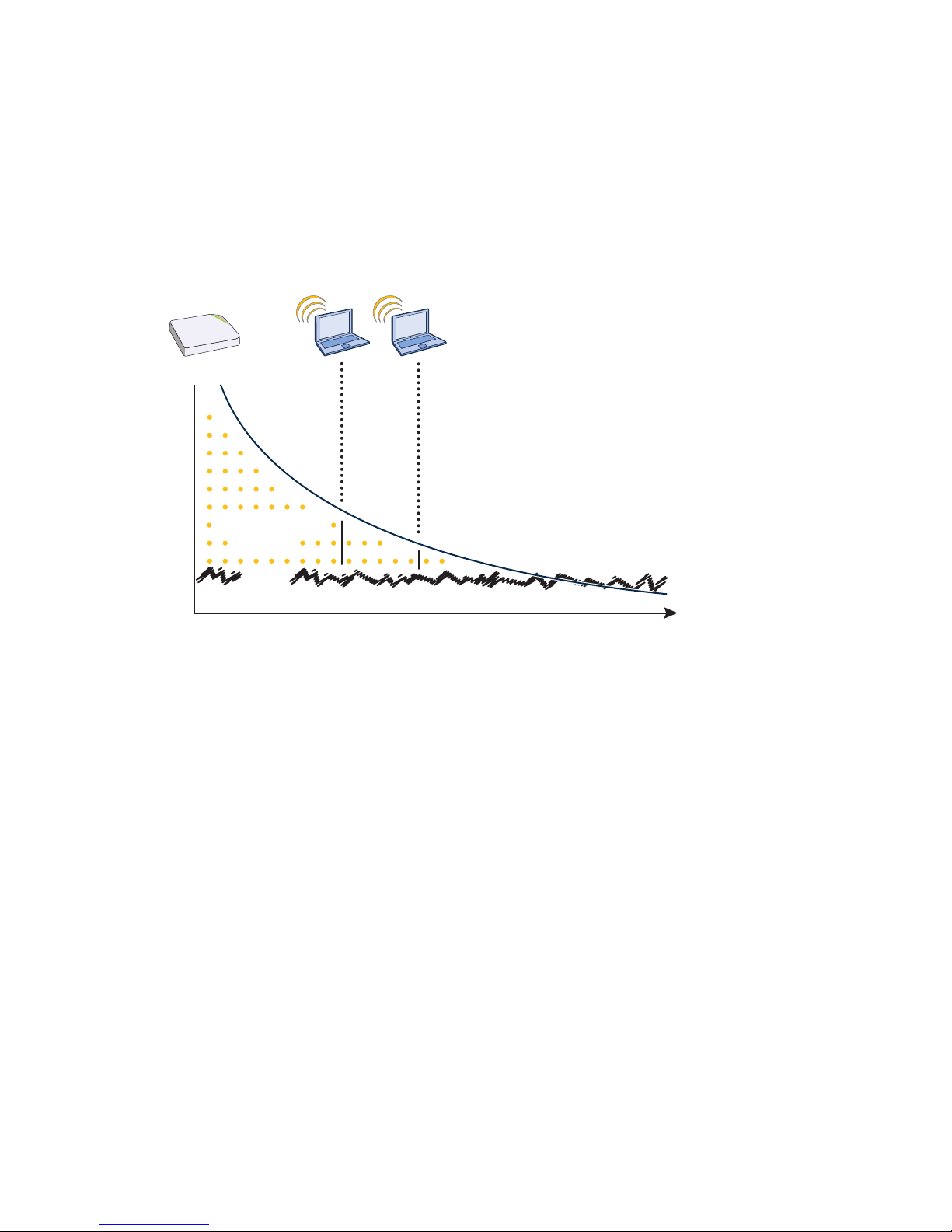
Chapter 2: Preparing for a WAN Deployment
Signal-to-Noise
Ratio
Distance
Noise
Received Signal
In RF, there is also a relative measurement that you can use to compare two numbers. This measurement is simply dB (without the
“m”). To see how this concept is applied, consider how radio signal propagation changes over a distance and how it can be
affected. Figure 2-3 shows signal strength over distance as a curve that has the best signal strength closer to the access point. It
also shows noise. In general, noise is considered to be low-level background RF signals that can interfere with a WLAN. This noise
tends to be the garbled background RF that comes from everything from the sun and stars to man-made interfering devices like
Bluetooth® headsets. It is impossible to block out noise, and it should not be attempted. This low level of background noise is
called the “noise floor.”
When clients send a packet, the ratio of the signal-to-noise (SNR) level defines the quality of the link, which is directly related to
the performance of the network. Based on the SNR, the client and AP negotiate a data rate in which to send the packet, so the
higher the SNR the better. For good performance, the SNR should be greater than 20 dB, and for optimal performance it should
be at least 25 dB.
Signal strength not only diminishes over distance, but it can also be affected by objects in the way (see Figure 2-4). This can be a
wall, a tree, or even a person. There is a fairly predictable dB drop through most objects that also decreases the SNR, thus
decreasing the data rate. Although this appears to be a bad thing, clever Wi-Fi installers use it to their advantage. It enables them
to place more access points in a tighter spot by using pre-existing walls and other impediments to Wi-Fi propagation to keep
them from interfering with each other.
Figure 2-10. Path loss in an open space.
724-746-5500 | blackbox.com
Page 31
Page 32

724-746-5500 | blackbox.com
Chapter 2: Preparing for a WAN Deployment
Signal-to-Noise
Ratio
Distance
Noise
Received Signal
Wall
Signal-to-Noise
Ratio
Distance
Noise
Received Signal
Figure 2-11. Path loss through a wall.
Microwave ovens, wireless video cameras, Bluetooth headsets, and cordless phones can all interfere with Wi-Fi signals (see Figure
2-5). Excess noise in an environment is often difficult to diagnose and can have a major negative impact on network performance.
To discover noise sources, a spectrum analysis system is needed. AirMagnet provides an affordable spectrum analysis tool that
operates in the 2.4-GHz and 5-GHz spectra.
Now that you have a sense of how Wi-Fi performance changes over distance and with noise, look at some ways to perform
channel assignment. If two access points are on the same channel right next to each other, they are forced to share the same
spectrum. This means that they share the 54-Mbps speeds available in 802.11a/g or the 300-Mbps speeds in 80211n rather than
each being capable of 54- or 300-Mbps speeds independently. This essentially halves the bandwidth for each access point. To
manage this situation, make sure that neighboring APs are on different channels and that their power is adjusted so that it does
not overlap that of other APs with the same channel.
Figure 2-12. Path loss with noise (from a microwave).
Page 32
724-746-5500 | blackbox.com
Page 33

Chapter 2: Preparing for a WAN Deployment
6460
52
56
36
44
40
6460
52
56
36
44
40
6460
52
56
36
44
40
6460
52
56
36
44
40
6460
52
56
36
44
40
6460
52
56
36
44
40
6460
52
56
36
44
40
7-to-1 Layout Pattern
116
1
116
1
61
11
61
11
111
6 111
6
6
1
11
6
1
11
11
61
3-to-1 Layout Pattern
1161
Primary Path
Secondary Path
Secondary Path
In the 2.4 GHz spectrum, there are 11 channels in the United States. However, a Wi-Fi signal consumes more than one channel.
Consequently, there are only 3 non-overlapping channels: 1, 6, and 11. To achieve optimal performance, you need to design a
channel layout pattern such as the one on the left in Figure 2-6.
Figure 2-13. Channel layout patterns.
NOTE: There are alternative 2.4-GHz channel layouts, such as one for four channels using 1, 4, 8 and 11 and another using
channels 1, 5, 9 to counter interference from microwaves, which tend to cause interference in the high end of the
spectrum. Black Box recommends alternative channel layouts only for the most challenging radio environments.
Designing a channel pattern is easier for the 5-GHz spectrum. Depending on the country and the device being used, there are
between 4 and 24 channels available for Wi-Fi use. However, in most countries there are at least eight 40-MHz-wide channels
with which to work. To simplify the layout of more than 3 channels, most use a 7-to-1 pattern, as is shown on the right in Figure
2-6. This channel layout is much more flexible than the 3-channel system and allows for much better capacity over all channels.
The last topic to cover is the concept of multipath. When a client receives a transmission from an access point (or vice versa), the
RF signal reaches the client first through a “direct path,” but then shortly thereafter by the “indirect paths” reflected off other
objects. The direct path combined with the indirect paths make up multipaths (see Figure 2-7). RF signals can bounce off almost
anything—walls, people, plants, and so on—but they bounce off metal most. As the RF signals bounce about while propagating,
one or more of the secondary paths can interfere with the primary path, causing the signal strength of the direct path to
diminish. In doing so, multipath can greatly decrease signal-to-noise ratio with legacy 802.11a/g radios. With 802.11n, a certain
amount of multipath is desirable and increases performance.
NOTE: If you would like to learn more about how radio-frequency propagation works or the details of 802.11, Wikipedia provides
excellent background information under the entries “IEEE 802.11,” “radio propagation,” and “multipath.” Additionally,
spending a few hours with a site survey tool such as AirMagnet Surveyor or the Ekahau Site Survey (ESS) and a few test
APs can increase both your familiarity with Wi-Fi propagation and your confidence about how it behaves.
Figure 2-14. Multipath radio waves.
724-746-5500 | blackbox.com
Page 33
Page 34

724-746-5500 | blackbox.com
Chapter 2: Preparing for a WAN Deployment
2.5 New and Enhanced SmartPath OS Features for Release 4.0r1
Spectrum Analysis: You can use up to ten SmartPath APs to function as spectrum analyzers for fixed lengths of time. You can
use the spectrum analyzer feature to monitor both the 2.4-GHz and 5-GHz bands. Each SmartPath AP performing spectrum analysis provides a real-time FFT (fast Fourier transform) trace that displays the frequency-power relationship, along with a swept spectrogram to monitor power and frequency changes over time. It also provides an FFT duty cycle trace that indicates how busy the
medium is, along with another swept spectrogram to monitor changes in the duty cycle over time. Additionally, SmartPath APs
can identify many sources of interference by their RF (radio frequency) signatures.
Access and Backhaul on the Same Radio: When operating SmartPath APs as mesh points, you can configure SmartPath AP
radios to operate simultaneously as an access interface and a backhaul interface. This not only provides a failover mechanism if
one of the wireless interfaces fails or loses connectivity, it also allows single radio implementations to service clients and act as
mesh points at the same time.
Automatic and Semi-Automatic Rogue Mitigation: In addition to manually mitigating rogue APs and their clients, you can
configure SmartPath APs to mitigate them automatically upon detection. You can also use a semi-automatic approach in which
you determine when to start the mitigation and allow the SmartPath APs to determine which SmartPath APs carry out the deauth
attacks that comprise the mitigation effort.
Private PSK Enhancements: You can set up a captive Web portal that allows users to self-register and receive their own
individual private PSKs. You can also configure SmartPath APs to generate private PSKs in bulk on a recurring basis with varying
expiration times. Finally, you can configure an SSID so that it automatically binds a private PSK to the MAC address of the first
client that uses it, reserving the key for exclusive use by that client until the private PSK lifetime expires or until an admin manually
unbinds it.
User Profile Reassignment: SmartPath APs can reassign users to different user profiles based on their MAC addresses or OUIs,
operating systems, and device domain names. This allows a user to go on the network with the same credentials, but be assigned
one user profile when using one type of device and a different profile when using another.
NetConfig UI: By default, SmartPath APs act as DHCP clients, so that when you put them on a network, they automatically
obtain appropriate network settings from a DHCP server. However, when a network uses static IP addressing, you must configure
network settings manually on all devices attached to that network. To ease deployment in such circumstances, SmartPath APs
support a NetConfig UI that allows you to ready a SmartPath AP for use on your network quickly and easily. The NetConfig UI is a
Web user interface through which you can manually configure the IP address, netmask, and gateway for a SmartPath AP and
configure SmartPath EMS VMA connectivity settings so that after the SmartPath AP is connected to the network, you can continue configuring and managing it through SmartPath EMS VMA.
IP Firewall Policy Support of Domain Names: IP firewall policies now support domain names as the source and destination in
their rules.
VMware PCoIP and Citrix ICA: With both PCoIP (PC-over-IP) and Citrix ICA (Independent Computing Architecture) desktop
virtualization protocols now predefined as services, you can quickly create firewall rules to allow or block these two services.
2.6 New and Enhanced SmartPath EMS VMA Features for Release 4.0r1
Active Directory Configuration Improvement: The internal processes used to connect to or query an Active Directory domain
are now more streamlined to simplify the initial setup required to integrate a SmartPath AP RADIUS server with an Active
Directory server. Also, you can now use SmartPath EMS VMA in Express mode to configure a SmartPath AP RADIUS server to
work with an Active Directory server—a feature formerly available only when using Enterprise mode.
RADIUS Authentication for VHM Administrators: In previous SmartPath EMS VMA versions, it was only possible to use
RADIUS authentication for home system administrators when no VHMs were present. Now both home system and VHM
administrators can be authenticated through an external RADIUS server.
Page 34
724-746-5500 | blackbox.com
Page 35

Chapter 2: Preparing for a WAN Deployment
CAPWAP Latency Reports: SmartPath EMS VMA tracks the average latency in its CAPWAP connections to each managed
SmartPath AP and displays an icon indicating the average amount of current latency in the Connection column on the Monitor >
Access Points > SmartPath APs page when viewed in Monitor mode. A green hexagon indicates normal latency, based on an
average that SmartPath EMS VMA has calculated from periodic SmartPath AP reports. The icon changes to yellow when the
latency increases to the point that responsiveness has slowed noticeably; however, configuration and image uploads can still
succeed. It changes to orange when connectivity issues reach the point that configuration and image upload attempts might no
longer be successful.
Online Planner: Several enhancements were made to improve the usability and accuracy of the on-line planner.
2.7 New and Enhanced SmartPath OS and SmartPath EMS VMA Features for Release 4.1r1
Selective Multicast Forwarding through GRE Tunnels: SmartPath APs can selectively block or allow broadcast and multicast
traffic through GRE tunnels to reduce traffic congestion. You can filter traffic either by using a blacklist to block all broadcast and
multicast traffic (or to block all except to a few select destinations) or by using a whitelist to allow all broadcast and multicast
traffic (or to allow all except to a few destinations).
Multiple Default Routing: It is now possible to configure multiple Layer 2 routes based on the VLAN ID of a user so that the
SmartPath AP can route Layer 2 traffic through different Ethernet interfaces as appropriate. This allows, for example, a guest user
on a corporate network segment to access a more appropriate segment for routing to the Internet while the SmartPath AP
forwards traffic from an employee on a different VLAN through a different Ethernet interface.
Captive Web Portal Enhancements: The default captive Web portal pages have been redesigned to resize automatically for
optimal viewing per device type: smartphone, tablet, and computer monitor. In addition, captive Web portals can now support a
registration page with buttons linking to various URLs.
IP Multicast Enhancements: To minimize airtime consumption caused by multicast frame transmissions, SmartPath APs can
convert multicast to unicast frames when channel use is high or multicast group membership is low. Furthermore, when a
SmartPath AP cannot detect any multicast group members among its active clients, it can automatically suppress multicast frame
transmissions completely.
LLDP Maximum Power: To avoid SmartPath APs sending LLDP (Link Layer Discovery Protocol) transmissions requesting more
power through PoE from the connecting switch than the switch can provide, you can set a maximum power level that SmartPath
APs can request in their LLDP advertisements on the Configuration > Advanced Configuration > Network Objects > LLDP/CDP
Profiles > New page. By default, the maximum is 15.4 watts.
724-746-5500 | blackbox.com
Page 35
Page 36

724-746-5500 | blackbox.com
Chapter 3: The SmartPath AP (LWN602HA) Overview
5 GHz (A)
5 GHz (B)5 GHz (C)
2.4 GHz (A) 2.4 GHz (B) 2.4 GHz (C)
ETH0
ETH1
48V DC
(.625A)
CONSOLE
RESET
3. The SmartPath AP (LWN602HA) Overview
The SmartPath AP is a high-performance and highly reliable 802.11n wireless access point. The SmartPath AP provides dual
concurrent 802.11b/g/n and 802.11a/n radios for 3x3 MIMO (Multiple In, Multiple Out) and dual 10/100/1000 Ethernet ports for
link aggregation or link redundancy. Its power management system uses a concept called smart Power over Ethernet (PoE) to
adjust its power consumption automatically in response to the available power in different environments. Smart PoE supports the
IEEE 802.3af and 802.3at standards.
3.1 Hardware Description
The SmartPath AP is a multichannel wireless access point. It is compatible with IEEE 802.11b/g/n (2.4 GHz) and IEEE 802.11a/n
(5 GHz) standards and supports a variety of wireless fidelity (Wi-Fi) security protocols, including Wi-Fi Protected Access (WPA) and
WPA2.
You can see the hardware components on the SmartPath AP in Figures 3-1 and 3-2. Each component is described in Table 3-1.
Device
Lock Slot
Status LEDs
802.11b/g/n RP-SMA Connectors for Detachable Single-Band Antennas
Figure 3-1. SmartPath AP front panel.
802.11a/n RP-SMA Connectors for Detachable Single-Band Antennas
10-/100-/ Power Console Reset
1000-Mbps Connector Port Button
PoE Ports
Figure 3-2. SmartPath AP back panel.
Page 36
724-746-5500 | blackbox.com
Page 37

Chapter 3: The SmartPath AP (LWN602HA) Overview
Table 3-1. SmartPath (LWN602HA) component descriptions.
Component Description
Status LEDs
Device lock slot
802.11a/b/g/n RP-SMA connectors
10- /100-/1000 -Mbps ports
The status LEDs convey operational states for system power, firmware, Ethernet
interfaces, and radios. For details, see Section 3.3, Status LEDs.
Y
ou can physically secure the SmartPath AP by attaching a lock and cable
(such as a Kensington
adapter that is included in the mounting kit and a padlock. For more information,
see “Locking the SmartPath AP” in Section 3.5.1, Ceiling Mount.
You can connect up to six detachable single-band antennas to the male
802.11a/b/g/n reverse polarity-subminiature version A (RP-SMA) connectors.
Connect the longer antennas, which support 2.4-GHz frequencies (for IEEE
802.11b/g /n), to the connectors on the side panel with the Ethernet ports.
Connect the shorter antennas, which support 5-GHz frequencies (for IEEE
802.11a/n), to the connectors on the side panel with the device lock slot.
For details, see Section 3.4, Antennas.
The two 10-/100-/1000-Mbps Ethernet ports—ETH0 and ETH1—support IEEE
802.3af and 802.3at PoE and have RJ-45 connectors. The SmartPath AP can
receive power through one or both Ethernet connections from power sourcing
equipment (PSE) that is compatible with the 802.3af standard and the 802.3at
standard, such as one of the PoE injectors available as an optional accessory from
Black Box. (If you connect the SmartPath AP to a power source through the power
connector and PoE ports simultaneously, the device draws power through the
power connector and automatically disables PoE.)
You can configure ETH0 and ETH1 as two individual Ethernet interfaces, combine
them into an aggregate interface to increase throughput, or combine them into a
redundant interface to increase reliability. You can connect the SmartPath AP to a
wired network or to a wired device (such as a security camera) through these
ports using bridging. They are compatible with 10/100/1000BASE-T/TX and automatically negotiate half- and full-duplex connections with the connecting device.
They are autosensing and adjust to straight-through and cross-over Ethernet
cables automatically. For details, see Section 3.2, Ethernet and Console Ports.
®
notebook lock) to the device lock slot or by using the lock
Power connector
Console port
Reset button
The 48-volt DC power connector (0.625 amps) is one of two methods through
which you can power the SmartPath AP. To connect it to a 100–240-volt AC
power source, use the AC/DC power adapter that is available as an extra option
(LWN600PS-US, LWN600PS-UK, or LWN600PS-EU). Because the SmartPath AP
does not have an on/off switch, connecting it to a power source automatically
powers on the device.
You can access the CLI by making a serial connection to the RJ-45 console port.
The management station from which you make a serial connection to the
SmartPath AP must have a VT100 emulation program, such as Tera Term Pro
(a free terminal emulator) or Hilgraeve
operating systems). The following are the serial connection settings: bits per second: 9600, data bits: 8, parity: none, stop bits: 1, flow control: none. For details,
see Section 3.2, Ethernet and Console Ports.
The reset button allows you to reboot the device or reset the SmartPath AP to its
factory default settings. Insert a paper clip, or something similar, into the Reset
pinhole and press the reset button. To reboot the device, hold the button down
between 1 and 5 seconds. To return the configuration to the factory default settings, hold it down for at least 5 seconds. After releasing the button, the Power
LED goes dark as the system reboots. Then it pulses green while the firmware
loads and the system performs a self-test. After the software finishes loading, the
Power LED glows steady green.
To disable the reset button from resetting the configuration, enter this command:
no reset-button reset-config-enable Pressing the button between 1 and 5 seconds
will still reboot the SmartPath AP, but pressing it for more than 5 seconds will not
reset its configuration.
®
Hyperterminal® (provided with Windows®
724-746-5500 | blackbox.com
Page 37
Page 38

724-746-5500 | blackbox.com
Chapter 3: The SmartPath AP (LWN602HA) Overview
ETH0
NOTE: The rear surface of the SmartPath AP is used for heat dissipation to reduce the internal temperature. Consequently, it can
become hot, so use caution when handling it.
3.2 Ethernet and Console Ports
There are three ports on the SmartPath AP: two RJ-45 10/100/1000BASE-T/TX Ethernet ports and an RJ-45 console port. The pin
assignments in the PoE (Power over Ethernet) Ethernet ports follow the TIA/EIA-568-B standard (see Figure 3-3 and Table 3-2).
The ports accept standard types of Ethernet cable—CAT3, CAT5, CAT5e, or CAT6—and can receive power over this cable from
power sourcing equipment (PSE) that is 802.3af-compatible. If you use CAT5, CAT5e, or CAT6 cables, the SmartPath AP can also
support 802.3at-compliant PSE. Such equipment can be embedded in a switch or router, or it can come from purpose-built devices that inject power into the Ethernet line en route to the SmartPath AP. Because the PoE ports have autosensing capabilities, the
wiring termination in the Ethernet cable can be either straight-through or cross-over.
8 1
Figure 3-3. View of the ETH0
PoE port on the SmartPath AP
(LWN602HA).
Pin Data Signal
1 Transmit + D C+ D C- — DC1+ DC1- DC1+ D C1-
2 Transmit - DC+ D C- — D C1+ DC1- DC1+ DC1-
3 Receive + D C- DC+ — D C1- DC1+ DC1 - DC1+
4 Not used — — D C+ DC2+ DC2+ DC2- DC2-
5 Not used — — D C+ DC2+ DC2+ DC2- DC2-
6 Receive - D C- D C+ — DC1- DC1 + DC1- D C1+
7 Not used — — D C- DC2- DC2- DC2+ DC2+
8 Not used — — D C- DC2- DC2- DC2+ DC2+
Table 3-2. PoE wire usage and pin assignments.
802.3af Alternative
A (Data and Power
on the Same Wires)
MDI MDI-X MDI or MDI-X 1 2 3 4
802.3af Alternative B
(Data and Power on
Separate Wires) 802.3at Wiring Options
MDI = Medium-dependent interface for straight-through connections.
MDI-X = Medium-dependent interface for crossover connections
The PoE ports are autosensing and can automatically adjust to transmit and receive data over straight-through or crossover
Ethernet connections. Likewise, they can automatically adjust to 802.3af Alternative A and B power delivery methods.
Furthermore, when the Alternative A method is used, the ports automatically allow for polarity reversals depending on their role
as either MDI or MDI-X. In 802.3at, the 1/2 and 3/6 wire pairs connect to DC source 1 and 4/5 and 7/8 pairs to DC source 2 in
PSE. Although the exact polarity depends on the PSE design, the SmartPath AP Ethernet ports can support all possible options.
Page 38
724-746-5500 | blackbox.com
Page 39

Chapter 3: The SmartPath AP (LWN602HA) Overview
Table 3-3. T568A Wire
Color.
Pin T568A Wire Color
1 White/Green
2 Green
1
8
Figure 3-4. T568A Terminated Ethernet Cable with an RJ-45 connector.
3 White/Orange
4 Blue
5 White/Blue
6 Orange
7 White/Brown
8 Brown
Table 3-4. T568B Wire
Color.
Pin T568A Wire Color
1
8
1 White/Orange
2 Orange
3 White/Green
4 Blue
5 White/Blue
6 Green
7 White/Brown
8 Brown
Figure 3-5. T568B Terminated Ethernet Cable with an RJ-45 connector.
T568A and T568B are two standard wiring termination schemes. Note that the only difference between them is that the white/
green + solid green pair of wires and the white/orange + solid orange pair are reversed.
For straight-through Ethernet cables—using either the T568A or T568B standard—the eight wires terminate at the same pins on
each end.
For cross-over Ethernet cables, the wires terminate at one end according to the T568A standard and at the other according to
T568B.
3.2.1 Smart PoE
The SmartPath AP (LWN602HA) applies the concept of smart PoE to adjust power consumption as necessitated by varying levels
of available power. The SmartPath AP supports PoE on both its ETH0 or ETH1 interfaces and can draw power through either one
or through both simultaneously. Based on the available power that the SmartPath AP detects, it manages its internal power use
by making the following adjustments:
724-746-5500 | blackbox.com
Page 39
Page 40

724-746-5500 | blackbox.com
Chapter 3: The SmartPath AP (LWN602HA) Overview
• No adjustments are needed when the power level is 20 W (watts) or higher. If the available power drops to a range between 18
and 20 W, the SmartPath AP disables its ETH1 interface, assuming that it is drawing power through its ETH0 interface. If it is
drawing power solely through its ETH1 interface, then it disables its ETH0 interface instead.
• If the power level drops to the 15–18 W range, the SmartPath AP then switches from 3x3 MIMO (Multiple In, Multiple Out) to
2x3 (see Section 3.4.1, MIMO).
• In rare cases when the power drops between 13.6 and 15 W and further power conservation is necessary, the SmartPath AP
reduces the speed on its active Ethernet interface—ETH0 or ETH1—from 10/100/1000 Mbps to 10/100 Mbps.
• Finally, if there is a problem with the PoE switch or Ethernet cable, and the power falls between 0 and 13.6 W, the SmartPath
AP disables its wireless interfaces and returns its ETH0 and ETH1 interfaces to 10-/100-/1000-Mbps speeds.
Through the application of smart PoE, the SmartPath AP can make power usage adjustments so that it can continue functioning
even when the available power level drops.
3.2.2 Aggregate and Redundant Interfaces
By default ETH0 and ETH1 act as two individual Ethernet interfaces. When both interfaces are connected to the network and are
in backhaul mode, the SmartPath AP transmits broadcast traffic only through ETH0. The SmartPath AP transmits broadcast traffic
through ETH1 only when ETH0 does not have network connectivity. When both Ethernet interfaces are connected to the network
and are in access mode, then the SmartPath AP transmits broadcast traffic through all the access interfaces: ETH0, ETH1, and all
wireless subinterfaces in access mode.
In addition to using ETH0 and ETH1 as individual interfaces, you can combine them into an aggregate interface (agg0) to increase
throughput, or combine them into a redundant interface (red0) to increase reliability. The logical red0 and agg0 interfaces support
all the settings that you can configure for Ethernet interfaces except those pertaining to physical link characteristics such as link
speed. For configuration information, see the next sections.
Aggregate Interface
You can increase throughput onto the wired network by combining ETH0 and ETH1 into a single logically aggregated interface
called "agg0". The aggregate interface effectively doubles the bandwidth that each physical interface has when used individually.
In this configuration, both Ethernet ports actively forward traffic, the SmartPath AP applying an internal scheduling mechanism
based on the source MAC address of each packet to send traffic through the aggregate member interfaces. To configure an
aggregate interface, enter the following commands:
interface eth0 bind agg0
interface eth1 bind agg0
In addition to configuring the SmartPath AP, you must also configure the connecting switch to support EtherChannel. For example, the following commands bind two physical Ethernet ports—0/1 and 0/2—to the logical interface port-channel group 1 on a
Cisco® Catalyst® 2900 switch running Cisco IOS 12.2:
Switch#conf t
Switch(config)#interface port-channel 1
Switch(config-if)#switchp ort mode access
Switch(config-if)#spanning-tree portfast
Switch(config-if)#exit
Switch(config)#interface fastEthernet 0/1
Switch(config-if)#switchp ort mode access
Switch(config-if)#channel-group 1 mode on
Switch(config-if)#spanning-tree portfast
Page 40
724-746-5500 | blackbox.com
Page 41

Chapter 3: The SmartPath AP (LWN602HA) Overview
Switch(config-if)#exi
Switch(config)#int fastEthernet 0/2
Switch(config-if)#switchp ort mode access
Switch(config-if)#channel-group 1 mode on
Switch(config-if)#spanning-tree portfast
Switch(config-if)#exit
Switch(config)#exit
Switch#wr mem
Finally, you must cable the Cisco switch and the SmartPath AP together: Cisco 0/1 to SmartPath AP eth0, and Cisco 0/2 to
SmartPath AP eth1.
Redundant Interface
If a single Ethernet link provides sufficient bandwidth and speed, such as a 1000-Mbps link, but you want to ensure link redundancy, you can connect the two Ethernet ports to the same switch—or to two different switches—and configure them to act as
a redundant interface called "red0". In this mode, only one Ethernet interface is actively forwarding traffic at any one time. If eth0
is active and eth1 is passive and eth0 loses its connection, the SmartPath AP switches over to eth1. To configure a redundant
interface, enter the following commands:
interface eth0 bind red0 primary
interface eth1 bind red0
The interface that you specify as primary is the one that the SmartPath AP uses when both interfaces have network connectivity.
Because the SmartPath AP uses eth0 as the primary interface by default, it is unnecessary to specify “primary” in the first
command above. However, it is included to make the role of eth0 as the primary interface obvious.
NOTE: No extra configuration is necessary on the connecting switch or switches to support a redundant interface.
Interface Selection for the Default Route
In cases where there are multiple active interfaces in backhaul mode, the SmartPath AP uses the following logic to choose which
interface to use in its default route:
• If there is an Ethernet interface and a wireless interface in backhaul mode, the SmartPath AP uses the Ethernet interface in its
default route.
• If there are multiple Ethernet interfaces in backhaul mode, the SmartPath AP chooses which one to use in its default route in
the following order:
- It uses red0 or agg0 if one of them has at least one member interface bound to it and its link state is UP.
- It uses ETH0 if neither red0 nor agg0 has any member interfaces and the link state for ETH0 is UP.
- It uses ETH1 if neither red0 nor agg0 has any member interfaces, the link state for ETH0 is DOWN, and the link state for ETH1 is
U P.
3.2.3 Console Port
The pin-to-signal mapping in the RJ-45 console port is shown shown in Figure 3-6.
724-746-5500 | blackbox.com
Page 41
Page 42
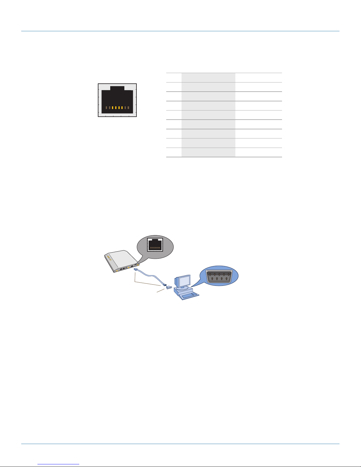
724-746-5500 | blackbox.com
Chapter 3: The SmartPath AP (LWN602HA) Overview
CONSOLE
Rollover Cable with
RJ-45 Connectors
RJ-45-to-Female DB-9 Adapter
Console Port
COM Port
(on Back Panel)
CONSOLE
Management System
SmartPath AP
Table 3-5. Console port pin assignments.
8 1
Pin Signal Direction
1 RTS (Request to Send) Output, unused
2 DTR (Data Terminal Ready) Output, unused
3 TXD (Transmitted Data) Output
4 Ground Ground
5 Ground Ground
6 RXD (Received Data) Input
Figure 3-6. View of the console
port on the SmartPath AP
(LWN602HA).
To make a serial connection between your management system and the SmartPath AP, you can use the console cable that is
available as an extra accessory. Insert the RJ-45 connector into the SmartPath AP console port and attach the DB9 connector to
the serial (or COM) port on your management system. The management system must have a VT100 terminal emulation program,
such as Tera Term Pro (a free terminal emulator) or Hilgraeve Hyperterminal (provided with Windows operating systems). If you
want to make your own serial cable and adapter, refer to Figure 3-7 and Table 3-6.
7 DSR (Data Set Ready) Input, unused
8 CTS (Clear to Send) Input, unused
Figure 3-7. Wiring details for making a serial cable with an RJ-45-to-female DB9 adapter.
Page 42
Management System
724-746-5500 | blackbox.com
Page 43

Chapter 3: The SmartPath AP (LWN602HA) Overview
Table 3-6. Wiring details for making a serial cable with an RJ-45-to-female DB9 adapter.
Console Port
(LW N602H A) RJ-45 -to-RJ-45 Rollover Cable RJ-45-to-Female DB9 Adapter Management System
Signal RJ- 45 Pin R J- 45 Pin RJ-45 Pin DB9 Pin Signal
RTS (Request to Send) 1 8 1 8 CTS (unused)
DTR (Data Terminal Ready) 2 7 2 6 DSR (unused)
TXD (Transmitted Data) 3 6 3 2 RXD
Ground 4 5 4 5 Ground
Ground 5 4 5 1 Ground
RXD (Received Data) 6 3 6 3 TXD
DSR (Data Set Ready) 7 2 7 4 DTR (unused)
CTS (Clear to Send) 8 1 8 7 RTS (unused)
— — — — 9 RI (Ring Indicator, unused)
3.3 Status LEDs
The five status LEDs on the top of the SmartPath AP indicate various states of activity through their color (dark, green, amber, and
red) and illumination patterns (steady glow or pulsing).
Power
• Dark: No power
• Steady green: Powered on and the firmware is running normally
• Pulsing green: Firmware is booting up
• Steady amber: Firmware is being updated
• Pulsing amber: Alarm indicating a firmware issue has occurred
• Steady red: Alarm indicating a hardware issue has occurred
ETH0 and ETH1
• Dark: Ethernet link is down or disabled
• Steady green: 1000-Mbps Ethernet link is up but inactive
• Pulsing green: 1000-Mbps Ethernet link is up and active
• Steady amber: 10-/100-Mbps Ethernet link is up but inactive
• Pulsing amber: 10-/100-Mbps Ethernet link is up and active
WIFI0 and WIFI1
• Dark: Wireless interface is disabled
• Steady green: Wireless interface is in access mode but inactive
• Pulsing green: Wireless interface is in access mode and active
• Steady amber: Wireless interface is in backhaul mode but inactive
• Pulsing amber: Wireless interface is in backhaul mode and is connected with other cluster members
• Alternating green and amber: Wireless interface is in backhaul mode and is searching for other cluster members
724-746-5500 | blackbox.com
Page 43
Page 44

724-746-5500 | blackbox.com
Chapter 3: The SmartPath AP (LWN602HA) Overview
5 GHz Antenna for IEEE
802.11a/n
Length when fully
extended: 5 15/16” (15 cm)
2.4 GHz Antenna for
IEEE 802.11b/g/n
Length when fully
extended: 7 7/8” (20 cm)
3.4 Antennas
Antennas are an integral part of the SmartPath AP. The SmartPath AP can accept up to six detachable dipole antennas. The three
shorter antennas are designed for the 5-GHz band and have a 2-dBi gain. The three longer antennas are designed for the
2.4-GHz band and have a 4.9-dBi gain. These antennas are omnidirectional, providing fairly equal coverage in all directions in a
toroidal (donut-shaped) pattern around each antenna (see Figure 2-1). For greater coverage on a horizontal plane, it is best to orient the antennas vertically. So that you can easily do that whether the SmartPath AP chassis is mounted horizontally or vertically,
the antennas hinge and swivel (see Figure 3-8).
Although cluster members automatically adjust their signal strength according to their environments, you can resize the area of
coverage by increasing or decreasing the signal strength manually by entering the interface { wifi0 | wifi1 } radio power <number>
command, where <number> can be from 1 to 20 and represents a value in dBm.
2.4-GHz Antenna
for IEEE 802.11b/g/n
Length when fully
extended: 77⁄8"
(20 cm)
5-GHz Antenna
for IEEE 802.11a/n
Length when fully
extended: 515⁄16"
(15 cm)
The base of the antennas hinge up to 90 degrees so that
you can orient the antennas independently of the orientation
of the SmartPath AP chassis. The antennas also rotate
in a full circle.
Figure 3-8. SmartPath AP (LWN602HA) antennas.
Page 44
724-746-5500 | blackbox.com
Page 45
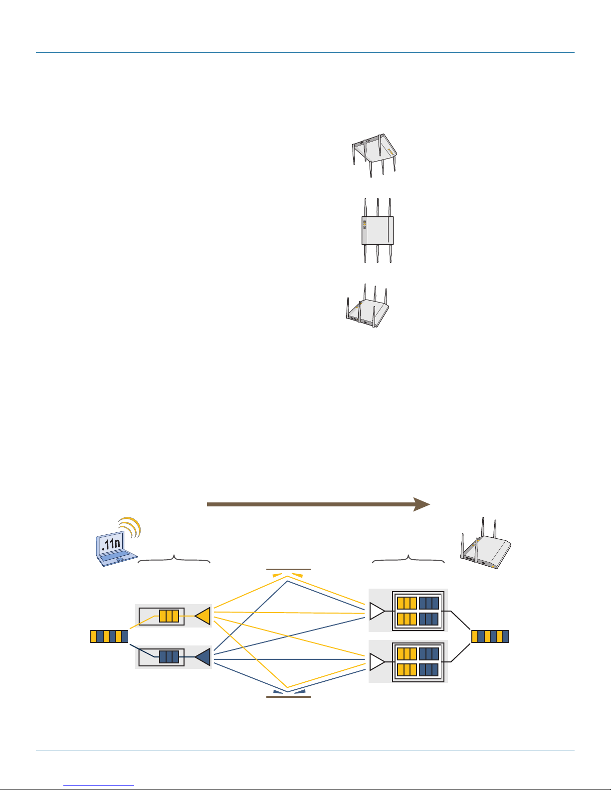
Chapter 3: The SmartPath AP (LWN602HA) Overview
Transmit
Antennas
Digital Signal
Processors
RF Chains RF Signals (Multipath)
Receive
Antennas
Digital Signal
Processors
RF Chains
802.11n wireless client
with two antennas
SmartPath AP using
two antennas
Object
Data
Reassembled
Data
Generally, orient the antennas vertically
for improved radio coverage, as shown here:
When mounting the SmartPath
AP (LWN602HA) on a ceiling,
orient its antennas downward.
When mounting the SmartPath AP
on a wall or post, fully extend its
antennas upward and downward.
When mounting the SmartPath AP
above a ceiling or on a horizontal
beam, orient its antennas upward.
Figure 3-9. SmartPath AP antennas, installed.
3.4.1 Multiple In, Multiple Out (MIMO)
Multiple In, Multiple Out (MIMO) is a major WLAN advancement introduced in the IEEE 802.11n standard in which multiple RF
links are formed on the same channel between the transmitter and receiver simultaneously. To accomplish this, the transmitter
separates a single data stream into multiple spatial streams, one for each RF chain (an antenna + various digital signal processing
modules linked to the antenna). The transmit antennas at the end of each RF chain then transmit their spatial streams. The recipient’s receive antennas obtain streams from all the transmit antennas. In fact, because of multipath, they receive multiple streams
from each transmit antenna. The receive antennas pass the spatial streams to the digital signal processors in their RF chains, which
take the best data from all the spatial streams and reassemble them into a single data stream once again (see Figure 3-10).
Data
Figure 3-10. 2x2 MIMO (2 transmit antennas x 2 receive antennas).
724-746-5500 | blackbox.com
Page 45
Page 46
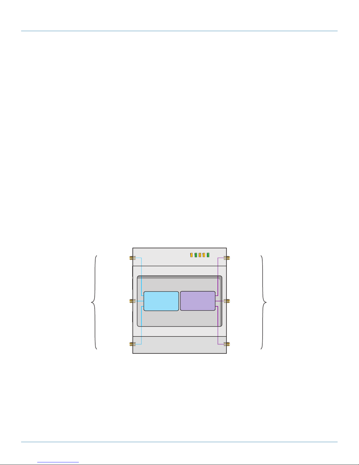
724-746-5500 | blackbox.com
Chapter 3: The SmartPath AP (LWN602HA) Overview
PWR
ETH1
ETH0
WIFI1
WIFI0
Radio 1
RF 802.11b/g/n
2.4 GHz
Radio 2
RF 802.11a/n
5 GHz
2.4 GHz (A)
2.4 GHz (B)
2.4 GHz (C)
5 GHz (A)
5 GHz (B)
5 GHz (C)
RP-SMA
Connectors
RP-SMA
Connectors
In previous 802.11 standards, access points and clients each used a single set of components, or RF chain, for transmitting or
receiving. Although two antennas are often used for diversity, only the one with the best signal-to-noise ratio is used at any given
moment, and that antenna makes use of the single RF chain while the other antenna remains inactive. A significant improvement
that MIMO introduces is to permit each antenna to have its own RF chain and for all antennas to function simultaneously. For the
SmartPath AP, you can connect up to three antennas per radio and configure the radio to use two or three transmit chains and
two or three receive chains.* Using two or three transmit and receive chains simultaneously increases the amount of data that can
flow across the WLAN and accelerates the processing of that data at each end of the wireless link.
*The convention for presenting the configuration of transmitting and receiving MIMO RF chains is TxR. For example, a SmartPath
AP radio functioning in access mode might be configured to use two RF chains for transmitting and three for receiving. In that
case, its configuration can be presented as “2x3.” In general, the number of receive antennas is equal to or greater than the
number of transmit antennas.
Another major aspect of MIMO is how it turns multipath signals from a curse to a boon. As a radio signal moves through space,
some objects reflect it, others interfere with it, and still others absorb it. The receiver can end up receiving multiple copies of the
original signal, all kind of muddled together. However, the digital signal processors in the multiple receive chains are able to
combine their processing efforts to sort through all the received data and reconstruct the original message. Furthermore, because
the transmitter makes use of multiple RF chains, there is an even richer supply of signals for the receive chains to use in their
processing. To set the transmit and receive RF chains for a radio profile, enter the following commands:
radio profile <name> transmit-chain { 2 | 3 }
radio profile <name> receive-chain { 2 | 3 }
There are two sets of antennas—three antennas per set—that operate concurrently in two different frequency ranges: 2.4 GHz
(IEEE 802.11b/g/n) and 5 GHz (IEEE 802.11a/n). Using two different frequency ranges reduces the probability of interference that
can occur when numerous channels operate within the same range. Conceptually, the relationship of antennas and radios is
shown in Figure 3-11.
Cut-away view of the SmartPath AP to show the relationship of the antennas and the two internal radios
Figure 3-11. Antennas and radios.
The wifi0 interface links to radio 1 (frequency range = 2.4 GHz for IEEE 802.11b/g), and the wifi1 interface links to radio 2
(frequency range = 5 GHz for IEEE 802.11a). These interface-to-radio relationships are permanent.
When deciding how many antennas to use, consider the types of wireless clients—802.11n only, 802.11g/n, 802.11b/g/n, or
802.11a/n—the area needing coverage, and the RF environment.
Page 46
724-746-5500 | blackbox.com
Page 47

Chapter 3: The SmartPath AP (LWN602HA) Overview
3.4.2 Using MIMO with Legacy Clients
In addition to supporting up to 300-Mbps throughput per radio for 802.11n clients, MIMO can improve the reliability and speed
of legacy 802.11a/b/g client traffic. When an 802.11a/b/g access point does not receive acknowledgement that a frame it sent
was received, it resends that frame, possibly at a somewhat lower transmission rate. If the access point must continue resending
frames, it will continue lowering its transmission rate. As a result, clients that could get 54-Mbps throughput in an interferencefree environment might have to drop to 48- or 36-Mbps speeds because of multipath interface. However, because MIMO
technology makes better use of multipath, an access point using MIMO can continue transmitting at 54 Mbps, or at least at a
better rate than it would in a pure 802.11a/b/g environment, thus improving the reliability and speed of 802.11a/b/g client traffic.
Although 802.11a/b/g client traffic can benefit somewhat from an 802.11n access point using MIMO, supporting such legacy
clients along with 802.11n clients can have a negative impact on 802.11n client traffic. Legacy clients take longer to send the same
amount of data as 802.11n clients. Consequently, legacy clients consume more airtime than 802.11n clients do, causing greater
congestion in the WLAN and reducing 802.11n performance.
By default, the SmartPath AP supports 802.11a/b/g clients. You can restrict access only to clients using the IEEE 802.11n standard.
By only allowing traffic from clients using 802.11n, you can increase the overall bandwidth capacity of the access point so that
there will not be an impact on 802.11n clients during times of network congestion. To do that, enter the following command:
radio profile <string> 11n-clients-only
You can also deny access just to clients using the IEEE 802.11b standard, which has the slowest data rates of the three legacy
standards, while continuing to support 802.11a and 802.11g clients. To do that, enter the following command:
no radio profile <string> allow-11b-clients
By blocking access to 802.11b clients, their slower data rates cannot clog the WLAN when the amount of wireless traffic
increases.
3.5 Mounting the SmartPath AP (LWN602HA)
Using the mounting plate and track clips, you can mount the SmartPath AP to the tracks of a dropped ceiling grid. Using just the
mounting plate, you can mount the SmartPath AP to any surface that can support its weight (3.3 lb., 1.5 kg).
This document covers the following methods for mounting the SmartPath AP (LWN602HA):
• Section 3.5.1, Ceiling Mount—Using the mounting plate and track clips, you can mount the SmartPath AP to the tracks of a
dropped ceiling grid so that it is suspended upside down against the ceiling.
• Section 3.5.2, Plenum Mount—Using the mounting plate, hanger clip, and hanger frame, you can mount it in the plenum
above a dropped ceiling.
• Section 3.5.3, Suspended Mount—Using the mounting plate, cable, quad-toggle, and locking device, you can suspend the
device from a beam, bracket, or any object that can support its weight (3.3 lb. [1.5 kg]).
• Section 3.5.4, Surface Mount—Using just the mounting plate and some screws or nails, you can mount the SmartPath AP
directly to any surface that can support its weight.
NOTE: In addition to these methods, you can also mount the SmartPath AP on a table using the set of four rubber feet that ship
with the product. Simply peel the rubber feet off the adhesive sheet and press them against the underside of the
SmartPath AP in its four corners.
3.5.1 Ceiling Mount
To mount the SmartPath AP to a standard 1"-wide track in a dropped ceiling, you need the mounting plate, two track clips, and
two Keps nuts that ship with the SmartPath AP. You also need a drill, a wrench, and—most likely—a ladder. Nudge the ceiling
tiles slightly away from the track to clear some space. Attach the track clips to the ceiling track, and then fasten the mounting
plate to the clips, as shown in Figure 3-12. When you have the mounting plate in the correct location, cut or drill a hole in the
ceiling. Use it to pass through the Ethernet and power cables.
724-746-5500 | blackbox.com
Page 47
Page 48

724-746-5500 | blackbox.com
Chapter 3: The SmartPath AP (LWN602HA) Overview
Mounting Plate
1
2
Press the track clips against the
ceiling track and swivel them until
they snap into place, gripping the
edges of the track.
If necessary, slide one or both of
the clips along the track to position
them at the proper distance (2 1/4”
or 7 cm) to fit through the holes in
the mounting plate.
Insert the mounting plate over the
screws attached to the track clips,
and use the Keps nuts to fasten
the plate firmly to the screws on
the clips.
Use a wrench to tighten the nuts
firmly to the bolts and secure the
plate to the track.
3
Through the oblong opening in the
plate, drill a hole in the ceiling tile (not
shown). Then pass one or both
Ethernet cables through the hole, and
if you plan to supply power from an
AC power source rather than through
PoE, pass the power cable through
as well.
Drill a hole in the ceiling tile
and feed cables through here.
Ceiling Track
Track Clip
(worms’s eye view with ceiling
tiles removed for clarity)
2 1/4 “ (7 cm)
Worm’s eye view with ceiling
tiles removed for clarity.
21⁄4" (7 cm)
21⁄4"
Figure 3-12. Attaching the track clips and mounting plate to the ceiling track.
Attach the SmartPath AP to the mounting plate and connect the cables, as shown in Figure 3-13.
NOTE: You can tie the cables to the tie points (small arched strips) on the mounting plate to prevent them from being pulled out
Page 48
of their connections accidentally.
724-746-5500 | blackbox.com
Page 49

With the SmartPath AP upside
down, align its port side with
the bottom end of the plate.
Push the SmartPath AP
upward, inserting the four tabs
on the plate into the four slots
on the SmartPath AP.
Slide the SmartPath AP toward
the bottom end of the plate,
locking the tabs inside the slots.
Attach the antennas and connect the
cables to complete the installation.
4
6
7
5
Tab
inside
slot.
Tab
locked in
place.
Mounting Plate
SmartPath AP (shown as transparent for clairty)
Tab
Slot
(side view)
Mounting Plate
SmartPath AP
Ceiling
Cables pass through the hole in
the mounting plate and ceiling
(side view)
5 GHz (A)
5 GHz (B)5 GHz (C)
Rotate the
lock adapter
clockwise.
Insert a lock
through the
opening.
Chapter 3: The SmartPath AP (LWN602HA) Overview
Ceiling
Figure 3-13. Attaching the SmartPath AP to the mounting plate and connecting cables.
When done, adjust the ceiling tiles back into their former position.
Locking the SmartPath AP (LWN602HA)
To lock the SmartPath AP to the mounting plate, use either a Kensington lock or the lock adapter that is included with the
mounting kit and a small padlock (not included).
To use a Kensington lock, loop the cable attached to the lock around a secure object, insert the T-bar component of the lock into
the device lock slot on the SmartPath AP, and then turn the key to engage the lock mechanism.
To use the lock adapter:
1. Insert the T-shaped extension on the adapter into the device lock slot, and rotate it clockwise so that the curved section
extends through the slot in the mounting plate (see Figure 3-14).
Insert a lock
through the
opening.
Figure 3-14. Locking the SmartPath AP to the mounting plate.
SmartPath AP
Mounting plate
2. Link a padlock through the opening in the adapter and engage the lock to secure the SmartPath AP to the mounting plate.
The opening is
1
⁄8" (0.3 cm) in diameter at its narrowest.
724-746-5500 | blackbox.com
Page 49
Page 50

724-746-5500 | blackbox.com
Chapter 3: The SmartPath AP (LWN602HA) Overview
With the SmartPath AP upside
down, align its port side with
the bottom end of the plate.
Push the SmartPath AP
upward, inserting the four tabs
on the plate into the four slots
on the SmartPath AP.
Slide the SmartPath AP toward
the bottom end of the plate,
locking the tabs inside the slots.
Attach the antennas to the
antenna connectors.
3
Tab
inside
slot.
Tab
locked in
place.
Mounting Plate
SmartPath AP (shown as transparent for clairty)
Tab
Slot
(side view)
3.5.2 Plenum Mount
To mount the SmartPath AP in the plenum space above a dropped ceiling grid, you need the mounting plate, hanger clip, and a
standard 24"-wide hanger frame, which can be ordered separately (call Black Box Technical Support at 724-746-5500 for details).
1. With the recessed side of the mounting plate facing downward, insert the hanger clip through the large hole in the center of
the plate.
2. Squeeze the clip until the projecting tabs at the ends of its two feet snap into the smaller holes on both sides of the larger hole
(see Figure 3-15).
Insert the hanger clip through the large hole in the mounting plate.
Squeeze the hanger clip to pull the tabs on its feet inward until they snap upward into the two holes on either side of the larger
hole.
Hanger clip
3. Attach the SmartPath AP to the mounting plate, and then attach the antennas to the connectors (see Figure 3-16).
side view
Figure 3-15. Fitting the hanger clip to the mounting plate.
Mounting
plate
Mounting Plate
Figure 3-16. Attaching the SmartPath AP to the mounting plate.
Page 50
724-746-5500 | blackbox.com
Page 51

Chapter 3: The SmartPath AP (LWN602HA) Overview
4. Remove the ceiling tile next to the area where you want to mount the device.
5. Press the hanger frame downward into place on the ceiling track until the claws on each leg grips the track below the top
ridge (see Figure 3-17).
Remove the ceiling tile and enter the plenum.
Press the hanger frame onto the ceiling track.
Figure 3-17. Clipping the hanger frame onto the track.
6. Insert the hanger clip upward through the center slot in the hanger frame, and then twist it counterclockwise until the clip
snaps into a locked position against the sides of the crossbar (see Figure 3-18).
724-746-5500 | blackbox.com
Page 51
Page 52

724-746-5500 | blackbox.com
Chapter 3: The SmartPath AP (LWN602HA) Overview
SmartPath AP attached
Bird’s eye view with the ceiling
tiles and ceiling tracks removed
for clarity
Insert the hanger clip
upward through the center
slot in the hanger frame.
Rotate the SmartPath AP and the
attached mounting accessories counterclockwise until the clip locks in
place against the sides of the crossbar.
to the mounting plate
Hanger frame
Figure 3-18. Securing the SmartPath AP to the hanger frame.
7. Connect one or two Ethernet cables to the network, and—if not using PoE—connect the power cord to a power source.
8. Replace the ceiling tile to complete the installation.
3.5.3 Suspended Mount
You can suspend the SmartPath AP from a horizontal beam, post, strut, or girder. As well as the mounting plate, you need a
quad-toggle, a 1.5 mm (0.059 inch) wire rope with hook, and a locking device. ERICO® supplies these items in its CADDY® SPEED
LINK product line. The part number for the quad-toggle is SLD15QT250 and that for the set that includes the wire rope, hook,
and locking device is SLD15L2T. These items are available through various suppliers.
1. With the recessed side of the mounting plate facing downward, insert the four ends of the quad-toggle through holes in the
mounting plate.
2. Turn the SmartPath AP face down and attach it to the mounting plate (see Figure 3-19).
To secure each of the four strands to the mounting plate:
1. Insert the metal cleat at the end of a strand through a hole in the plate.
2. Sliding the oblong washer along the strand; pass it through the hole.
3. Pull the strand upward to lock the cleat and washer against the underside of the plate.
To attach the SmartPath AP to the mounting plate:
1. Align the tabs on the plate with the wider, circular section of the keyhole shaped slots on the underside of the device, which is
face down as shown.
Page 52
724-746-5500 | blackbox.com
Page 53
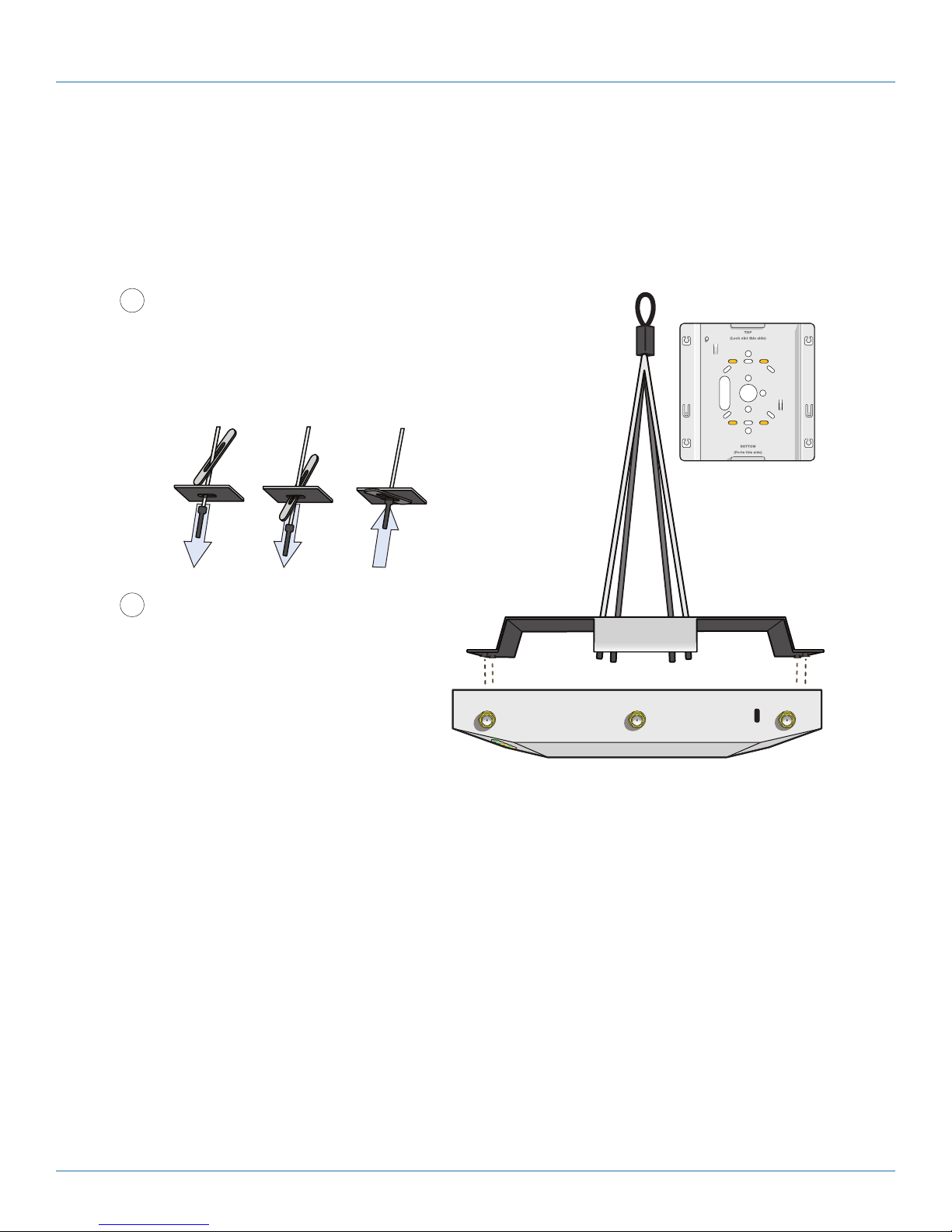
Chapter 3: The SmartPath AP (LWN602HA) Overview
5 GHz (A)
5 GHz (B)5 GHz (C)
To secure each of the four strands to the mounting plate:
1. Insert the metal cleat at the end of a strand through a hole
in the plate.
2. Sliding the oblong washer along the strand, pass it through
the hole.
3. Pull the strand upward to lock the cleat and washer against
the underside of the plate.
To attach the SmartPath AP to the mounting plate:
1. Align the tabs on the plate with the wider,
circular section of the keyhole-shaped slots
on the underside of the device, which is
face down as shown.
2. Push the tabs into the slots and slide the
SmartPath AP toward its port panel. This
repositions the tabs in the narrower,
rectangular section of the slots and holds
the device firmly in place below the
mounting plate.
1
2
Mounting Plate
The recommended
holes for the four
strands are shaded in.
2. Push the tabs into the slots and slide the SmartPath AP toward its port panel. This repositions the tabs in the narrower,
rectangular section of the slots and holds the device firmly in place below the mounting plate.
Mounting Plate
The recommended holes for the four strands are shaded in.
Mounting plate
3. Draw the wire rope over a support beam, fasten the hook around the wire, and pull the wire until the hook is snug against the
underside of the beam.
Figure 3-19. Connecting the quad-toggle and SmartPath AP to the mounting plate.
4. Push the plain end of the wire rope—the end without the hook—through the side hole in the locking device in the direction
indicated by the arrow on its side, and then pass it through the loop at the end of the quad-toggle.
5. Insert the wire rope back through the center hole in the locking device, and then continue pulling it through the locking device
until the SmartPath AP is suspended at the height you want (see Figure 3-20).
The center tube that runs through the locking device is designed to allow you to pull the rope wire up through it while prevent-
ing the rope from slipping back down. If you ever pull too much rope through and need to pull it back down, use a tool such
as a screwdriver to press against the inner tube in the locking device to release the rope. Then you can pull it back out (see
“Height Correction,” next page).
724-746-5500 | blackbox.com
Page 53
Page 54

724-746-5500 | blackbox.com
Chapter 3: The SmartPath AP (LWN602HA) Overview
Clip
3
Wrap the wire rope around a beam, clip the hook to the rope, and
then pull the rope downward until it is taut against the beam.
Pull downward
on the rope.
Beam
Locking
Device
Loop at Top of
Quad-Toggle
Quad-Toggle
Mounting Plate
SmartPath AP
Locking Device
4
Push the wire rope through the
side hole in the locking device
and then through the loop in the
quad-toggle.
5
Pass the wire rope upward through the
center hole in the locking device, and
continue pulling the rope to raise the
SmartPath AP to the height you want.
Press against the lip of
the inner tube and hold.
While pushing the tube inward, pull the wire rope out.
Locking Device
Wire Rope Screw Driver
Clip
Locking
Device
Loop at Top of
Quad Toggle
Quad Toggle
Mounting Plate
Figure 3-20. Suspending the SmartPath AP.
6. Attach antennas to the antenna connectors on the SmartPath AP, connect one or two Ethernet cables to the network, and—
if not using PoE—connect the power cord to a power source.
Height Correction
If you accidentally pull too much wire rope through the locking device, raising the SmartPath AP too high, and you then need to
lower it, do the following: Take a tool, such as a screwdriver with a
opposite direction from the arrow on the outside of the locking device (see Figure 3-21). This releases its grip on the rope,
enabling you to pull out the rope the same way it was inserted. While maintaining pressure on the tube, adjust the rope until the
SmartPath AP is at the height you want. When you are satisfied, stop pressing against the tube so that it can regain its grip on
1
⁄8" flat tip, and press it against the lip of the inner tube in the
the rope.
Press against the lip
Locking Device
of the inner tube and
hold.
While pushing the tube inward, pull the rope out.
Figure 3-21. Releasing the wire rope from the locking device.
Page 54
Wire Rope
724-746-5500 | blackbox.com
Screwdriver
Page 55

Chapter 3: The SmartPath AP (LWN602HA) Overview
Mounting Plate
SmartPath AP
Wall
3.5.4 Surface Mount
You can use the mounting plate to attach the SmartPath AP to any surface that supports its weight, and to which you can screw
or nail the plate. First, mount the plate to the surface. Then, through one of the two large openings in the plate, make a hole in
the wall so that you can pass the cables through to the SmartPath AP.
NOTE: You can tie the cables to the tie points on the mounting plate to prevent them from being pulled out of their connections
accidentally.
Finally, attach the device to the plate, and connect the cables, as shown in Figure 3-22.
1. With the two wings at the sides
of the plate extending away from
the surface, attach the mounting
plate to a secure object such as a
wall or beam. Use #8 screws
for the oblong holes, and #10
for the larger round ones.
2. Cut or drill a hole through one of
the openings in the mounting plate
to pass the cables through to the
SmartPath AP.
3. Insert the tabs on the mounting
plate into the slots on the underside
of the SmartPath AP. Then push the
SmartPath AP downward to lock it
in place.
Mounting Plate
4. Connect the cables to the
SmartPath AP.
Depending on the deploy-
ment, you might connect one
or two Ethernet cables and a
power cable.
Wall
NOTE: There are a variety of holes through which you
Figure 3-22. Mounting the SmartPath AP on a wall.
can screw or nail the plate in place. Choose the
two or three that best suit the object to which
you are attaching it.
724-746-5500 | blackbox.com
Page 55
Page 56

724-746-5500 | blackbox.com
Chapter 3: The SmartPath AP (LWN602HA) Overview
3.6 Device, Power, and Environmental Specifications
Understanding the range of specifications for the SmartPath AP is necessary for optimal deployment and device operation. The
following specifications describe the physical features and hardware components, the power adapter and PoE electrical requirements, and the temperature and humidity ranges in which the device can operate.
Device Specifications
• Chassis dimensions: 8.5" W x 1.25" H x 8" D (21.5 x 3.2 x 20.3 cm)
• Weight: 3 lb. (1.36 kg)
• Antennas: Three omnidirectional 802.11b/g/n antennas, and three omnidirectional 802.11a/n antennas
• Serial port: RJ-45 (bits per second: 9600, data bits: 8, parity: none, stop bits: 1, flow control: none)
• Ethernet ports: autosensing 10/100/1000 Mbps; both ports are compliant with the IEEE 802.3af standard and the forthcoming
802.at standard for PoE (Power over Ethernet)
Power Specifications
• AC/DC power adapter:
• Input: 100–240 VAC
• Output: 48 V/0.625 A
• PoE nominal input voltages:
• 802.3af: 48 V/0.35 A
• Pre-802.3at: 48 V/0.625 A
• RJ-45 power input pins: Wires 4, 5, 7, 8 or 1, 2, 3, 6
Environmental Specifications
• Operating temperature: -4 to +131° F (-20 to +55° C)
• Storage temperature: -40 to +176° F (-40 to +80° C)
• Relative Humidity: Maximum 95%
Page 56
724-746-5500 | blackbox.com
Page 57

Chapter 4: The SmartPath AP (LWN602A) Overview
Reset PinDevice Lock Slot ETH0
PoE Port
48 VDC
Status Indicator
4. SmartPath AP (LWN602A) Overview
The SmartPath AP LWN602A is a high-performance wireless access point suitable for small offices, mobile employees, and tele-
commuters. The SmartPath AP has two radios—one for 802.11a/n and one for 802.11b/g/n, both of which can operate concurrently. Both platforms provide 2x2 MIMO and a single 10/100/1000 Ethernet port through which they can be powered using PoE
that follows the IEEE 802.3af standard or the 802.3at pre-standard. Optionally, they can be powered by an AC/DC desktop power
adapter.
NOTE: SmartPath AP (LWN602A) devices support 802.11n features. Of particular interest is their support of 2x2 MIMO. For more
information, see Section 3.4.1, MIMO and Section 3.4.2, Using MIMO with Legacy Clients.
4.1 Hardware Description
The SmartPath AP (LWN602A) is a multichannel wireless access point. It contains a dual-band radio that can operate at either 2.4
GHz or 5 GHz—but not in both bands simultaneously. The SmartPath AP contains a 2.4-GHz radio and a 5-GHz radio that can
operate concurrently through four internal antennas. The SmartPath AP supports a variety of Wi-Fi security protocols, including
WPA, and WPA2.
You can see the hardware components on the SmartPath AP in Figure 4-1. Each component is described in Table 4-1.
Status Indicator
Device Lock Slot
Figure 4-1. SmartPath LWN602A hardware components.
Reset Pin
724-746-5500 | blackbox.com
ETH0
PoE Port
48 VDC
Page 57
Page 58

724-746-5500 | blackbox.com
Chapter 4: The SmartPath AP (LWN602A) Overview
Table 4-1. SmartPath AP component descriptions.
Component Description
Status Indicator
The status indicator conveys operational states for system power, firmware updates, Ethernet and wireless interface activity, and major alarms. For details, see Section 4.3, Status Indicator.
Device Lock Slot
Reset Button
ETH0 PoE Port
48-VDC Power Connector
You can physically secure the SmartPath AP by attaching a Kensington lock and cable to the device lock slot. For
more information, see Locking the SmartPath AP in Section 4.5.1, Ceiling Mount.
The reset button allows you to reboot the device or reset the SmartPath AP to its factory default settings. Insert a
paper clip, or something similar, into the Reset pinhole and press the reset button. To reboot the device, hold the
button down between 1 and 5 seconds. To return the configuration to the factory default settings, hold it down
for at least 5 seconds. After releasing the button, the status indicator goes dark as the system reboots. Then it
glows blue while the device boots and the system performs a self-test. After the firmware finishes loading and
the SmartPath AP is ready to serve clients, the status indicator glows white.
To disable the reset button from resetting the configuration, enter this command: no reset-button reset-configenable. Pressing the button between 1 and 5 seconds will still reboot the SmartPath AP, but pressing it for more
than 5 seconds will not reset its configuration.
The 10- /100 -/1000-Mbps Ethernet port— ETH0— receives an RJ-45 connector. The SmartPath AP can receive
power through an Ethernet connection to the ETH0 port from power sourcing equipment (PSE) that is compatible
with the 802.3af standard and the forthcoming 802.3at standard. Black Box provides suitable PoE injectors as an
optional accessory. (If you connect the SmartPath AP to a power source through the power connector and the
ETH0 PoE port simultaneously, the device draws power through the power connector and automatically disables
PoE.)
The ETH0 port is compatible with 10 /100/1000BASE-T/ TX and automatically negotiates half- and full-duplex
connections with the connecting device. It is autosensing and adjusts to straight-through and cross-over Ethernet
cables automatically. For details, see Section 4.2, Ethernet Port.
The 48-volt DC power connector (0.3 amps), with a voltage range of 36 to 57 volts DC, is one of two methods
through which you can power the SmartPath AP (the other is PoE). To connect it to a 100 – 240 -volt AC power
source, use the AC/DC power adapter that is available as an extra accessory. Because the SmartPath AP does not
have an on/off switch, connecting it to a power source automatically powers on the device.
4.2 Ethernet Port
The pin assignments in the PoE 10/100/1000BASE-T/TX Ethernet port follow the TIA/EIA-568-B standard (see Figure 3-3 and
Table 3-2). The port accepts standard types of Ethernet cable—CAT3, CAT5, CAT5e, or CAT6—and can receive power over the
Ethernet cable from PSE that is 802.3af compatible. If you use CAT5, CAT5e, or CAT6 cables, the ETH0 port can also support
802.3at-compliant PSE. Such equipment can be embedded in a switch or router, or it can come from purpose-built devices that
inject power into the Ethernet line en route to the SmartPath AP. Because the PoE port has autosensing capabilities, the wiring
termination in the Ethernet cable can be either straight-through or cross-over.
4.3 Status Indicator
The status indicator has been incorporated into the Black Box logo on the top of the SmartPath AP LWN602A. It is illuminated by
various colors to indicate different states of activity. The meanings of the colors are as follows:
• Dark: There is no power or the status indicator is disabled.
• Blue: solid: The device is booting up or there is no backhaul link; flashing: the device is shutting down.
• Green: The default route is through the backhaul Ethernet interface, but not all conditions for normal operations (white) have
been met.
Page 58
724-746-5500 | blackbox.com
Page 59

Chapter 4: The SmartPath AP (LWN602A) Overview
Bright Soft DimOff
Radio 1
RF 802.11b/g/n
2.4 GHz
Radio 2
RF 802.11a/n
5 GHz
5 GHz
Antenna
5 GHz
Antenna
2.4 GHz
Antenna
2.4 GHz
Antenna
• Yellow: The default route is through a backhaul Wi-Fi interface, but not all conditions for normal operations (white) have been
met.
• White: The device is powered on and the firmware is operating normally; that is, a wireless interface in access mode is up,
a wired or wireless backhaul link is up, and the SmartPath AP has a CAPWAP connection to either SmartPath EMS VMA or a
management AP.
• Purple: A new image is being loaded from SmartPath EMS VMA or a management AP.
• Orange: An alarm indicating a firmware or hardware issue has occurred.
For locations where the status indicator might be a distraction or attract unwanted attention, you can adjust its brightness level
from bright (the default) to soft to dim. You can even turn it off completely. In SmartPath EMS VMA, choose the brightness level
that you want from the LED Brightness drop-down list on the Configuration > Management Services > Management Options
page. Through the CLI, enter [ no ] system led brightness { soft | dim | off }. The four settings are represented graphically in Figure
4-2.
Bright Soft Dim Off
Figure 4-2. Adjustable status indicator brightness levels.
4.4 Antennas
Antennas are an integral part of the SmartPath AP (LWN602A). The SmartPath AP LWN602A has four internal single-band
antennas. Two of the antennas operate in the 2.4-GHz band (IEEE 802.11b/g/n) and have a 0-dBi gain. The other two antennas
operate in the 5-GHz band (IEEE 802.11a/n) and have a 3-dBi gain. All antennas are omnidirectional, providing fairly equal cover-
age in all directions in a cardioid (heart-shaped) pattern around each antenna (see Figure 2-1).
On the SmartPath AP LWN602A, the two 2.4-GHz antennas link to one radio, and the two 5-GHz antennas link to the other
radio, both of which can operate concurrently. The relationship of antennas and radios is shown in Figure 4-3.
5-GHz
antenna
2.4-GHz
antenna
2.4-GHz
antenna
5-GHz
antenna
Figure 4-3. Cut-away view of the SmartPath AP (LWN602A) showing the relationship of the internal antennas and radios.
724-746-5500 | blackbox.com
Page 59
Page 60
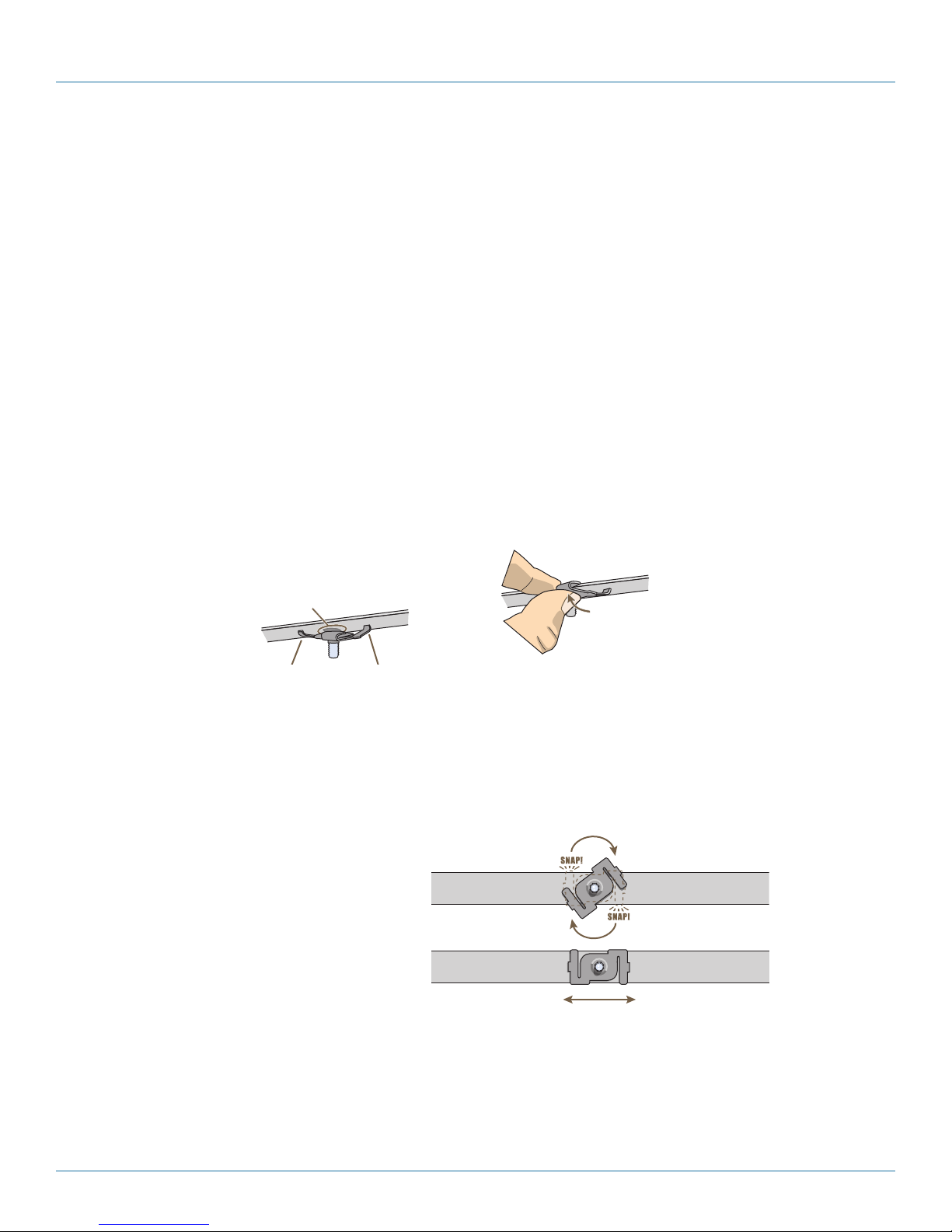
724-746-5500 | blackbox.com
Chapter 4: The SmartPath AP (LWN602A) Overview
1
Position the clip so one tab is over the
edge of the ceiling track. (The ceiling
track is shown as transparent to expose
the tab above the track.)
The two prongs press upward against
the middle of the ceiling track.
2
Press the other tab upward,
flexing the prongs against
the track until the tab clears
the edge of the track.
Twist the clip until the prongs
snap into place and grip the
edges of the track.
If necessary, slide the clip along
the track to position it exactly
where you want it to be.
(worms’s eye view with ceiling tiles removed for clarity)
3
4.5 Mounting a SmartPath AP (LWN602A)
Using one of the track clips included in the box with the SmartPath AP, you can mount it to a track in a dropped ceiling grid. To
mount the SmartPath AP to any flat surface that can support its weight (1.75 lb., 0.8 kg), use two #6 or #8 screws to mount it on
a wall and three screws to mount it on a ceiling.
NOTE: In addition to these methods, you can also mount the SmartPath AP on a table using the set of four rubber feet that ship
with the product. Simply peel the rubber feet off the adhesive sheet and press them against the underside of the
SmartPath AP in its four corners.
4.5.1 Ceiling Mount
To mount a SmartPath AP series device to a track in a dropped ceiling, use the appropriate track clip for the width of the ceiling
track. Two clips come with the SmartPath AP: one for 1" (2.54 cm) tracks and one for 1⁄2" (1.27 cm) tracks.
1. Nudge the ceiling tiles slightly away from the track to clear some space and slide one tab of the track clip over the edge of the
track.
2. With the tips of the track clip prongs positioned against the middle of the track, press upward on the other tab until it clears
the track edge, as shown in Figure 4-4. Keeping the prongs away from the track edges until both tabs grip the track ensures
that the clip does not snap into place prematurely with only one tab in position.
Position the clip so one tab is over the edge
of the ceiling track. (The ceiling track is shown
as transparent to expose the tab above the
track.)
The two prongs press upward
against the middle of the ceiling track.
Figure 4-4. Attaching the track clip to the ceiling track.
3. Twist the track clip until it snaps onto the ceiling track, as shown in Figure 4-5. You can then slide the clip along the track to
reposition it if necessary.
Twist the clip until the prongs snap
into place and grip the edges of
the track.
If necessary, slide the clip along the
track to position it exactly where you
want it to be.
4. Holding the SmartPath AP upside down, raise it until the threaded stud on the track clip enters the hole on the SmartPath AP.
Then rotate the SmartPath AP until it is firmly attached to the clip (see Figure 4-6).
Page 60
Figure 4-5. Securing the clip to the track and repositioning it if necessary.
Press the other tab upward,
flexing the prongs against
the track until the tab clears
the edge of the track.
Worms’s eye view with ceiling tiles removed for clarity
724-746-5500 | blackbox.com
Page 61
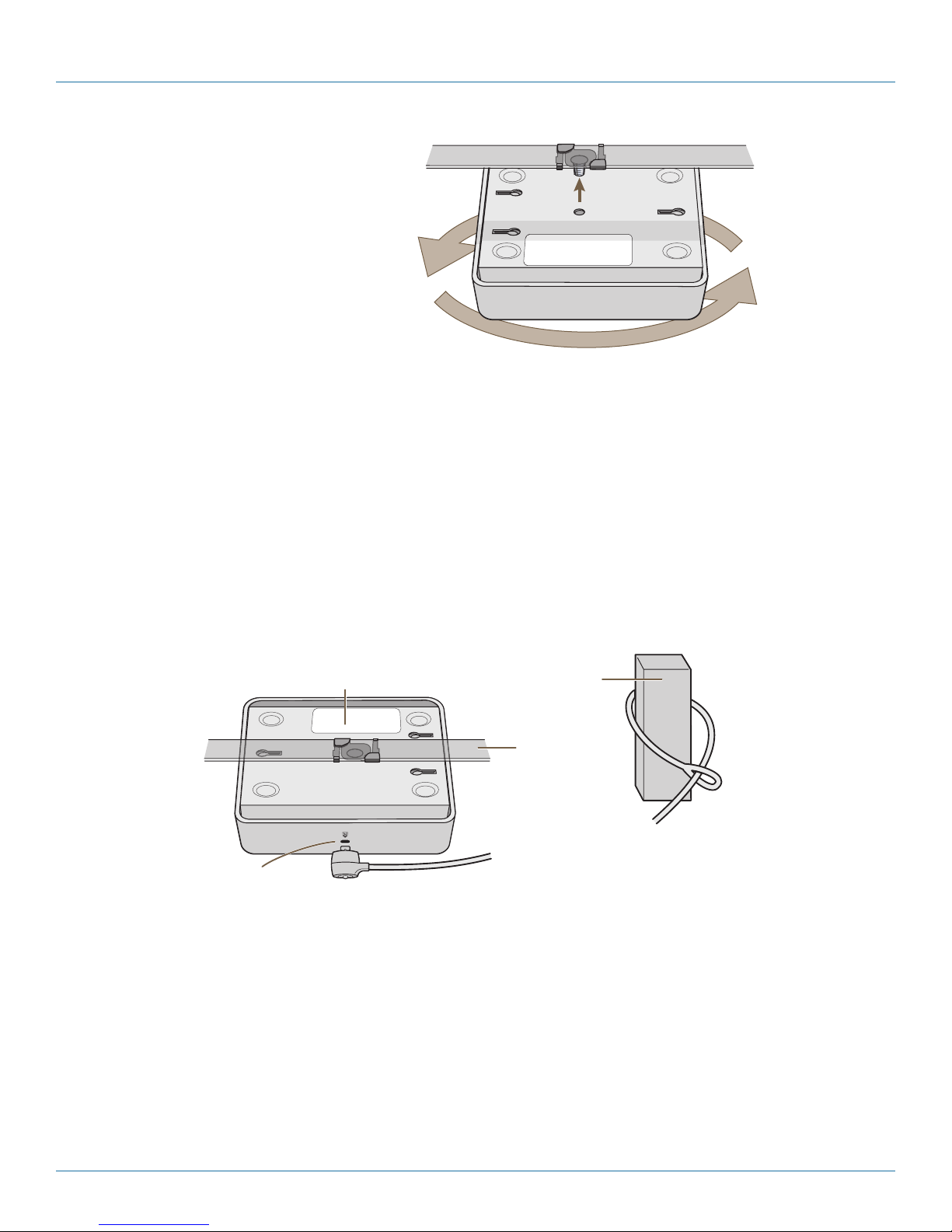
Chapter 4: The SmartPath AP (LWN602A) Overview
4
With the SmartPath AP upside
down, lift it until the threaded stud
on the track clip enters the hole in
the SmartPath AP. Revolve the
SmartPath AP until it is securely
attached to the clip.
SmartPath AP
Device Lock Slot
Kensington Security Lock
Loop the cable around a secure object, such
as a support beam, and then insert the T-bar
component of the lock into the device lock
slot on the SmartPath AP and turn the key to
engage the lock mechanism.
SmartPath AP mounted
to a ceiling track
Support Beam
Ceiling Track
(shown as
transparent)
With the SmartPath AP upside
down, lift it until the threaded stud
on the track clip enters the hole in
the SmartPath AP. Rotate the
SmartPath AP until it is securely
attached to the clip.
Figure 4-6. Attaching the SmartPath AP to the track clip.
5. When you have the SmartPath AP in the correct location, cut or drill a hole in the ceiling through which you can then pass the
Ethernet and power cables. Pass the cables through the hole and attach them to the SmartPath AP.
6. When done, adjust the ceiling tiles back into their former position.
NOTE: You can also mount the SmartPath AP to a solid ceiling—or the underside of any horizontal object such as a cross beam—
using three #6 or #8 screws. Position the three screws in a T-shaped layout: two screws 2" (5 cm) apart from each other
and the third screw center-aligned between them and 4.75" (12 cm) away. Then attach the SmartPath AP to the screws as
explained in Section 4.5.2, Surface Mount.
\
Locking the SmartPath AP
To lock the SmartPath AP to a secure object, use a Kensington lock and cable. Loop the cable around a securely anchored object,
insert the Kensington lock in the device lock slot in the SmartPath AP, and engage the locking mechanism (Figure 4-7).
4.5.2 Surface Mount
You can attach the SmartPath AP LWN602A to any flat surface that supports its weight. First, attach two screws to the surface.
Then, make a hole in the wall a few inches or centimeters above the screws so that you can pass the cables through the wall to
the SmartPath AP. Finally, attach the device to the screws, and connect the cables (see Figure 4-8).
Loop the cable around a secure object,
such as a support beam, and then insert the
T-bar component of the lock into the device
lock slot on the SmartPath AP and turn the
key to engage the mechanism.
Figure 4-7. Locking the SmartPath AP with a Kensington security lock.
724-746-5500 | blackbox.com
Page 61
Page 62

724-746-5500 | blackbox.com
Chapter 4: The SmartPath AP (LWN602A) Overview
1. Position two #6 or #8 screws 2" (5 cm) apart
and fasten them to a secure object such as a
wall, post, or beam.
2. Cut or drill a hole in the wall 1–2"
(2.5–5 cm) above the screws to pass
the cables through to the SmartPath AP.
3. Position the SmartPath AP so that the
screws enter the two upper keyhole-shaped
slots on the underside of the SmartPath AP.
Then push the SmartPath AP downward
to lock it in place.
4. Connect the cables to the SmartPath AP.
SmartPath AP
(LWN602A)
Instead of passing the cables through a hole in the wall, you can also simply run them along the wall from the port side of the
SmartPath AP, which is located at the top of the device when it is mounted on a wall.
Depending on the power source, you might
connect just one Ethernet cable or an
Ethernet cable and a power cord.
Figure 4-8. Mounting the SmartPath AP on a wall.
Wall
NOTE: You can use a Kensington lock to secure the SmartPath AP to a stationary object. For information, see “Locking the
SmartPath AP” in Section 4.5.1.
4.6 Device, Power, and Environmental Specifications
Understanding the specifications for the SmartPath AP LWN602A is necessary for optimal deployment and device operation. The
following specifications describe the physical features and hardware components, the power adapter and PoE (Power over
Ethernet) electrical requirements, and the temperature and humidity ranges in which the device can operate.
Device Specifications
• Chassis dimensions: 6.5" W x 2" H x 6.5" D (16.3 cm W x 4.6 cm H x 16.3 cm D)
• Weight: 1.75 lb. (0.8 kg)
• Antennas: SmartPath AP (LWN602A): two omnidirectional 802.11b/g/n antennas, and two omnidirectional 802.11a/n antennas
• Ethernet port: one autosensing 10/100/1000 Base-T/TX Mbps port; compliant with the IEEE 802.3af standard and the 802.at
standard for PoE (Power over Ethernet)
Power Specifications
• DC Input: 36 - 57VDC (48 V/0.3A)
• PoE input:
• 802.3af
• Pre-802.3at
• RJ-45 power input pins: Wires 4, 5, 7, 8 or 1, 2, 3, 6
Environmental Specifications
• Operating temperature: +32 to +104 degrees F (0 to +40 degrees C)
• Storage temperature: -40 to +185 degrees F (-40 to +85 degrees C)
• Relative Humidity: Maximum 95% noncondensing
Page 62
724-746-5500 | blackbox.com
Page 63
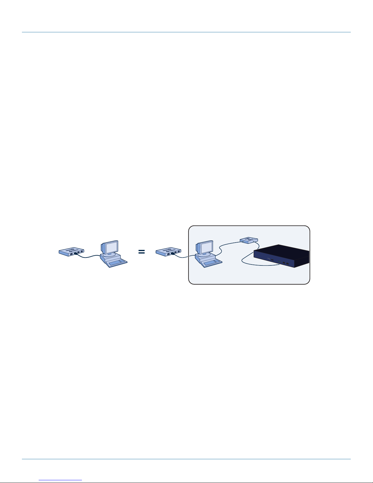
Chapter 5: The SmartPath EMS
Virtual Layer 2 Switch
Computer
10.1.1.5/24
Computer Hosting SmartPath
EMS VMA Virtual Appliance
SmartPath EMS VMA
10.1.1.8/24
Logical view of the computer hosting
SmartPath EMS VMA Virtual Appliance
Switch
to
network
Switch
to
network
5. The SmartPath EMS
The SmartPath Enterprise Management System (EMS), available as a cloud-based service (LWN600CM-1 or LWN600CM-3) or as a
virtual management appliance (VMA) (LWN600VMA), is a GUI for centrally configuring and monitoring the APs as well as setting
security and guest log-in parameters.
• Simplified installations and management of up to 2000 SmartPath APs
• Profile-based configurations that simplify the deployment of large numbers of SmartPath APs
• Scheduled firmware upgrades on SmartPath APs by location
• Exportation of detailed information on SmartPath APs for reporting
Server Requirements
Minimum Hardware:
Processor: Dual-core 2 GHz or better
Memory: 2 GB dedicated to SmartPath EMS Virtual Appliance, at least 1 GB for the computer hosting it
Disk: 60 GB dedicated to SmartPath EMS Virtual Appliance
Figure 5-1. Typical application.
724-746-5500 | blackbox.com
Page 63
Page 64

724-746-5500 | blackbox.com
Chapter 6: SmartPath EMS VMA Online (Cloud-Based Service)
Virtual PC
10.1.1.5/24
SmartPath EMS
10.1.1.8/24
Admin’s PC
10.1.1.5/24
Virtual
Switch
SmartPath.blackbox.com
SmartPath EMS Online SmartPath EMS Virtual Appliance
SwitchSwitch
Firewall
Internal Network
10.1.1.0/24
Managed
SmartPath APs
Managed
SmartPath APs
Internal Network
10.1.1.0/24
6. SmartPath EMS VMA On-line (Cloud-Based Service)
In addition to a SmartPath EMS VMA, the SmartPath EMS VMA network management system is available in one other form.
SmartPath EMS Online is a cloud-based service running on hardware hosted and maintained by Black Box (see Figure 6-1). This
management system provides cost-effective alternatives for managing WLAN networks that might not require the investment of a
physical appliance.
Figure 6-1. SmartPath EMS Online. Figure 6-2. SmartPath EMS VMA.
Black Box hosts SmartPath EMS Online at smartpath.blackbox.com, maintaining the SmartPath EMS VMA hardware and updating
the SmartPath EMS VMA software as new releases become available. You receive access to a VEMS (virtual SmartPath EMS VMA)
running on the SmartPath EMS VMA hardware. Each VEMS is an independent management system with its own administrators
managing their own set of SmartPath APs. Without the expense of buying a physical appliance or SmartPath EMS VMA Virtual
Appliance, SmartPath EMS Online can be the most cost-efficient choice for managing a small number of SmartPath APs.
After purchasing SmartPath EMS Online, you receive your login URL and credentials in an e-mail message. After logging in, you
enter the SmartPath landing space. From there, you can access your VEMS.
Through your VEMS, you can manage SmartPath APs deployed remotely. By default, SmartPath APs first try to connect
to a local SmartPath EMS VMA. If the MAC address or serial number of the SmartPath AP is already assigned to a VEMS,
SmartPath.blackbox.com redirects the SmartPath AP to it (see Figure 6-2).
NOTE: Once ordered for use with the VEMS, the SmartPath APs will be preconfigured to try and reach the online VEMS
(SmartPath.blackbox.com).
NOTE: If you factory-reset an AP that has been provisioned to look for the online manager at SmartPath.Blackbox.com, it will
default to looking for a local EMS. You have to create an SSH connection to the AP and send two config lines using the
Enter:
VEMS CLI (see below).
Capwap client server primary name: Smartpath.blackbox.com and press the <Enter> key.
Save config run boot and press the <Enter> key
Once this is done, when the AP is connected to an Internet connection, the AP will look to the VEMS at SmartPath.blackbox.com
and show there.
Page 64
724-746-5500 | blackbox.com
Page 65

Chapter 6: SmartPath EMS VMA Online (Cloud-Based Service)
Home Page
Online
Server
VSPM-1
SmartPath.blackbox.com
Host Name Node ID . . .
. . .
Serial Number Virtual HM
BB-13C210 00197713C210 VSPM-112000831100034
Host Name: BB-13C210
Node ID: 00197713C210
Serial Number: 12000831100034
1
2
(1) The SmartPath AP initially forms a
CAPWAP connection with
SmartPath.blackbox.com.
(2) When the online server discovers an
entry for the SmartPath AP assigning it to
VSPM-1, it redirects the SmartPath AP to
that VSPM.
(3) When you log in to
SmartPath.blackbox.com
VSPM-1, you can see the
SmartPath AP listed on the
Monitor > Access Points >
SmartPath APs page.
Figure 6-3. Online server.
If the SmartPath AP MAC address or serial number is in Smartpath.blackbox.com, but not yet assigned to the VHM, the
SmartPath AP that forms a CAPWAP connection with Smartpath.blackbox.com remains connected to it. If the SmartPath AP MAC
address or serialnumber is not in Smartpath.blackbox.com, then Smartpath.blackbox.com does not respond to the CAPWAP
connection attempts from that SmartPath AP. For details about the initial CAPWAP connection process, see "How SmartPath APs
Connect to SmartPath EMS VMA" in Section 8.4.
6.1 Captive Web Portal Enhancements
The default captive Web portal pages have been redesigned to resize automatically for optimal viewing per device type: smartphone, tablet, and computer monitor. In addition, captive Web portals can now support a registration page with buttons linking
to various URLs.
Two significant enhancements have been made to the captive Web portal feature: the default pages have been revised, and
support for a new type of user registration has been added.
New Default Captive Web Portal Pages
With the proliferation of mobile devices, the default captive Web portal registration, success, and failure pages have been
redesigned to resize automatically to fit the screen of the device accessing them.
724-746-5500 | blackbox.com
Page 65
Page 66

724-746-5500 | blackbox.com
Chapter 6: SmartPath EMS VMA Online (Cloud-Based Service)
Registration Page with Links to Multiple URLs
You can create a custom registration page that has hyperlinks to various URLs. To register successfully, a user only has to click one
of the links. The act of clicking a link signals the SmartPath AP that the user has registered. After visiting the selected URL, the
user then has access to the rest of the network and can browse freely.
Here is a sample of the HTML code required for a SmartPath AP to register a user that has clicked a link:
<form name="form1" action="reg.php" method="post">
<input type="hidden" name="redir_url" value="http://www.Black Box.com"/>
<input type="hidden" name="checkbox" value="checkbox"/>
<img src="Black Box.gif" style="cursor:hand;" onClick="document.form1.submit();" />
</form>
In the preceding example, the redir_url parameter performs the same function as the Submit button on other registration pages.
When the SmartPath AP receives a request containing this parameter, which in this case occurs when a user clicks an image of
the Black Box logo (img src="Black Box.gif") on a form with the action set as reg.php, the method set as post, and an attribute
set with the value of checkbox, it then considers the user as having passed the registration process. You can add as many links to
the page as you like as long as each one has a different form name, such as "form1", "form2", "form3", and so on.
6.2 SmartPath Virtual Appliance
SmartPath Virtual Appliance (SmartPath EMS VMA) is similar to a physical appliance except that it is available as VMware that you
load onto a computer of your choice. SmartPath EMS VMA ships as VMware on a CD.
You must first install a VMware product such as VMware Workstation or VMware Player on your computer. Then install SmartPath
EMS VMA on the VMware workstation or player, where it runs like a virtual server inside your computer. SmartPath EMS VMA
forms a virtual Layer 2 connection to your computer—much as if the two were connected by a layer 2 switch internally—and
shares the Ethernet connection with your computer.
NOTE: You can find full installation instructions on the SmartPath EMS VMA Virtual Appliance QuickStart, which is also included on
the CD.
Page 66
724-746-5500 | blackbox.com
Page 67

Chapter 7: Using SmartPath EMS VMA
The management
plane is the logical division of
administrative traffic relating to the
configuration and monitoring of SmartPath APs.
From a management system, an admin can use the SmartPath
EMS to configure, maintain, and monitor multiple SmartPath APs,
essentially coordinating the control and data planes from a single, central location.
Data Plane
Control Plane
Management Plane
The data plane
is the logical division of
wireless client traffic (user data)
traversing a wireless-to-wired LAN. Traffic
in the data plane follows optimal paths
that various mechanisms in the control
plane determine.
The control plane is
the logical division of traffic that
Cluster members use to collaborate on
how best to forward user data, coordinate
radio frequencies, and provide Layer2
and Layer3 roaming capabilities with
each other.
To the wired
network ...
Management
System
7. Using SmartPath EMS VMA
Think of the cooperative control architecture as consisting of three broad planes of communication. On the data plane, wireless
clients gain network access by forming associations with SmartPath APs. On the control plane, SmartPath APs communicate with
each other to coordinate functions such as best-path forwarding, fast roaming, and automatic RF management. On the manage-
ment plane, SmartPath EMS VMA provides centralized configuration, monitoring, and reporting of multiple SmartPath APs. These
three planes are shown in Figure 7-1.
Figure 7-1. Three communication planes in the cooperative control architecture.
As you can see in Figure 7-1, SmartPath EMS VMA operates solely on the management plane. Any loss of connectivity between
SmartPath EMS VMA and the SmartPath APs it manages only affects SmartPath AP manageability; such a loss has no impact on
communications occurring on the control and data planes.
7.1 Installing and Connecting to the SmartPath EMS VMA GUI
To begin using the SmartPath EMS VMA GUI, you must first configure the MGT interface to be accessible on the network, cable
SmartPath EMS VMA and your management system (that is, your computer) to the network, and then make an HTTP connection
from your system to the MGT interface.
NOTE: SmartPath EMS VMA has two Ethernet interfaces—MGT and LAN. You can put just the MGT interface on the network
and use it for all types of traffic, or you can use both interfaces—which must be in different subnets—and separate
SmartPath EMS VMA management traffic (MGT) from SmartPath AP management traffic (LAN).
724-746-5500 | blackbox.com
Page 67
Page 68

724-746-5500 | blackbox.com
Chapter 7: Using SmartPath EMS VMA
Besides SmartPath EMS VMA and your management system, you need two or three Ethernet cables and a serial cable (or “null
modem”). The Ethernet cables can be standard CAT3, CAT5, CAT5e, or CAT6 cables with T568A or T568B terminations and
RJ-45 connectors. The serial cable must comply with the RS-232 standard and terminate on the SmartPath EMS VMA end with a
female DB9 connector. (For more details, see Section 5.2, Ethernet and Console Ports.)
The GUI requirements for the management system are as follows:
• Minimum screen resolution of 1280 x 1024 pixels
• Standard browser—Black Box recommends Internet Explorer® v7.0 or Mozilla® Firefox® v2.0.0 or later—with Flash v9.0 or later,
which is required for viewing charts with dynamically updated SmartPath AP alarms and wireless client data
Your management system also needs a VT100 terminal emulation program, such as Tera Term Pro (a free terminal emulator) or
Hilgraeve Hyperterminal (provided with Windows 95 to Windows XP operating systems).
Finally, you need an license key or, for a physical SmartPath EMS VMA appliance that does not have Internet access to the
entitlement server, a license key. You should have received this when you purchased your SmartPath EMS VMA software license.
Changing Network Settings
To connect SmartPath EMS VMA to the network, you must first set the IP address/netmask of its MGT interface so that it is in the
subnet to which you plan to cable it. To do this, you can use the SmartPath EMS VMA console port.
1. Connect the power cable to a 100–240-volt power source, and turn on SmartPath EMS VMA. The power switch is on the back
panel of the device.
2. Connect one end of an RS-232 serial cable to the serial port (or COM port) on your management system.
3. Connect the other end of the cable to the male DB9 console port on SmartPath EMS VMA.
4. On your management system, run a VT100 emulation program using the following settings:
• Bits per second (baud rate): 9600
• Data bits: 8
• Parity: none
• Stop bits: 1
• Flow control: none
5. Log in by entering the default user name (admin) and password (blackbox).
6. The SmartPath EMS VMA CLI shell launches. To change network settings, enter 1 (1 Network Settings and Tools),
and then enter 1 again (1 View/Set IP/Netmask /Gateway/DNS Settings).
7. Follow the instructions to configure the IP address and netmask for the MGT interface, its default gateway, the SmartPath EMS
VMA host name and domain name, and its primary DNS server.
NOTE: The default IP address/netmask for the MGT interface is 192.168.2.10/24. The default gateway IP address is 192.168.2.1.
The LAN interface is disabled by default and does not have a default IP address. You can define network settings for the
LAN interface through the SmartPath EMS VMA GUI after you log in.
When deciding to use one interface (MGT) or both (MGT and LAN), keep in mind that there are two main types of traffic to and
from SmartPath EMS VMA:
• SmartPath EMS VMA management traffic for admin access and file uploads
• SmartPath AP management traffic and configuration, file, and SmartPathOS image downloads to managed SmartPath APs
When you enable both interfaces, SmartPath EMS VMA management traffic uses the MGT interface while SmartPath AP manage-
ment traffic uses the LAN interface, as shown in Figure 7-2.
Page 68
724-746-5500 | blackbox.com
Page 69

Chapter 7: Using SmartPath EMS VMA
MGT
10.1.2.8/24
LAN
10.1.1.8/24
Switch
Router
Clusters in different subnets
Router
10.1.3.0/24
10.1.4.0/24
10.1.5.0/24
10.1.1.1
10.1.2.1
Admin
10.1.7.34
SCP Server
10.1.6.12
SmartPath EMS VMA
Each cluster contains
multiple SmartPath APs.
MGT
10.1.1.8/24
LAN
0.0.0.0/0
Switch Router Clusters in different subnets
10.1.3.0/24
10.1.4.0/24
10.1.5.0/24
10.1.1.1
Admin
10.1.7.34
SCP Server
10.1.6.12
SmartPath EMS VMA
Each cluster contains
multiple SmartPath APs.
Clusters in different subnets
Static Routes: SmartPath EMS VMA sends traffic destined for 10.1.6.0/24 to 10.1.2.1.
SmartPath EMS VMA sends traffic destined for 10.1.7.0/24 to 10.1.2.1.
Default Gateway: 10.1.1.1 (SmartPath EMS VMA sends traffic here when there are no specific routes to a destination.)
Figure 7-2. Using both MGT and LAN interfaces.
NOTE: To set static routes after you log in to the GUI, click Home > Administration > SmartPath EMS VMA Settings > Routing >
Add, set the destination IP address, netmask, and gateway, and then click “Apply.”
When only the MGT interface is enabled, both types of management traffic use it. A possible drawback to this approach is that
you cannot separate the two types of management traffic into two different networks. For example, if you have an existing man-
agement network, you would not be able to use it for SmartPath EMS VMA management traffic. Both SmartPath EMS VMA and
SmartPath AP management traffic would need to flow on the operational network because SmartPath EMS VMA would need to
communicate with the SmartPath APs from its MGT interface (see Figure 7-3). However, if the separation of both types of traffic
is not an issue, then using just the MGT interface is a simple approach to consider.
Clusters in different subnets
Each cluster contains
multiple SmartPath APs
Default Gateway: 10.1.1.1 (SmartPath EMS VMA sends all traffic to the default gateway.)
Figure 7-3. Using just the MGT interface.
8. After you finish configuring the network settings, restart network services by entering 6 (6 Restart Network Services) and then
enter yes to confirm the action. You can now disconnect the serial cable.
Connecting to the GUI through the MGT Interface
1. Connect Ethernet cables from the MGT interface and LAN interface—if you are using it—to the network.
2. Connect an Ethernet cable from your management system to the network so that you can make an HTTPS connection to the
IP address that you set for the MGT interface.
724-746-5500 | blackbox.com
Page 69
Page 70

724-746-5500 | blackbox.com
Chapter 7: Using SmartPath EMS VMA
3. Open a Web browser and enter the IP address of the MGT interface in the address field. For example, if you changed the IP
address to 10.1.1.8, enter this in the address field: https://10.1.1.8.
NOTE: If you ever forget the IP address of the MGT interface and cannot make an HTTPS connection to SmartPath EMS VMA,
make a serial connection to its console port and enter 1 for "Network Settings and Tools" and then 1 again for "View/Set
IP/Netmask/Gateway/DNS Settings.” The serial connection settings are explained in "Changing Network Settings" in
Section 7.1, Installing and Connecting to the SmartPath EMS VMA GUI.
A login prompt appears.
4. Type the default name (admin) and password (blackbox) in the login fields, and then click Log in.
Figure 7-4. Login screen.
5. After logging in to SmartPath EMS VMA Virtual Appliance, the Black Box End User License Agreement appears. Read it over,
and if you agree with its content, click Agree.
6. An initial "Welcome to SmartPath EMS VMA" dialog box appears as shown below.
Page 70
Figure 7-5. Welcome screen.
724-746-5500 | blackbox.com
Page 71

Chapter 7: Using SmartPath EMS VMA
Change the cluster name for your SmartPath APs (default: blackbox), change your SmartPath EMS VMA login password, and set
the time zone where you are located, which might be the same time zone as that for SmartPath EMS VMA or a different one. If
you have an entitlement key, click Enter Key. The following dialog box appears.
Figure 7-6. Entitlement key screen.
For a physical appliance with Internet access, select “Enter Entitlement Key.” Copy the entitlement key text string that Black Box
sent you in an e-mail message, paste it in the Entitlement Key field, and then click “Enter.” You also have the option of installing a
SmartPath EMS VMA license key, which is useful if you are working with an appliance in a location that does not have Internet
access, such as a test lab. If you already have a license, select “Install License Key,” copy the license key text string previously supplied by Black Box in an email message, paste it in the License Key field, and then click “Enter.”
For SmartPath EMS Online and SmartPath EMS VMA Virtual Appliance, copy the entitlement key text string, paste it in the
Entitlement Key field, and then click “Enter.” SmartPath EMS Online transmits the entitlement key to the on-line Black Box
entitlement server, which replies with all licenses associated with that key.
If you do not have an entitlement key or license key yet, click “Continue.” You can access the GUI for a 30-day period without a
key. To request an entitlement key or license key, you can send an e-mail to orders@blackbox.com. Make sure to include your
customer name and sales order number in the request. When you receive the key, click “Enter Now” in the prompt displayed at
the top of the GUI (shown below) or click Home > Administration > License Management. Copy the key from the e-mail and
paste it in the appropriate field.
Figure 7-7. GUI.
You are now logged in to the SmartPath EMS VMA GUI. Later, after completing the Global Settings page in the next steps, you
can check details about the installed entitlement key and licenses on the Home > Administration > License Management page.
You can also enter more licenses there if necessary.
7. SmartPath EMS VMA can operate in one of two administrative modes: Express and Enterprise. Express mode (the default)
provides a simple set of configuration components designed for managing a single network. Enterprise mode provides
configuration components for managing multiple networks that require more advanced settings. Because the examples
throughout this guide are based on Enterprise mode, switch to that mode by clicking Home > Global Settings and selecting
Enterprise (recommended for more advanced networks).*
*If you choose Express, you can later switch to Enterprise mode, and SmartPath EMS VMA will automatically convert your settings
from the structure used in Express mode to that used in Enterprise mode. However, after choosing Enterprise, you cannot later
switch to Express mode and preserve your settings. To change from Enterprise to Express mode, you must erase the database,
and then choose Express after you log back in.
8. After selecting Enterprise mode, you have the option of changing the root admin password for logging in to SmartPathAPs.
SmartPath EMS VMA uses this password when making SSH connections and uploading a full configuration to SmartPathAPs.
The default root admin name and password is admin and blackbox. To set a different password, enter it in the New SmartPath
AP Password and Confirm Password fields. The SmartPath AP password can be any alphanumeric string from 5 to 32
characters long. To see the password string that you enter, clear Obscure Password.
724-746-5500 | blackbox.com
Page 71
Page 72

724-746-5500 | blackbox.com
Chapter 7: Using SmartPath EMS VMA
Figure 7-8. Start here screen.
9. To save your settings and enter the SmartPath EMS VMA GUI in Enterprise mode, click “Update.”
10. A message appears prompting you to confirm your selection of Enterprise mode. After reading the confirmation message,
click “Yes.”
NOTE: You can change the SmartPath AP root admin name in the Credentials section of the SmartPath AP configuration dialog
box (Monitor > Access Points >SmartPath AP > smartpathap_name > Modify).
SmartPath EMS VMA displays the Guided Configuration page to assist you with the main configuration steps:
• Device-level settings for SmartPath APs
• The three major WLAN policy-level configuration objects, which reference all other configuration objects: user profiles,
SSIDs, and WLAN policies
• The transfer of the device- and policy-level settings from SmartPath EMS VMA to SmartPath APs
7.2 Introduction to the SmartPath EMS VMA GUI
Using the SmartPath EMS VMA GUI, you can set up the configurations needed to deploy, manage, and monitor large numbers of
SmartPath APs. The configuration workflow is described in Section 7.3. The GUI consists of several important sections, which are
shown in Figure 7-9.
Page 72
724-746-5500 | blackbox.com
Page 73
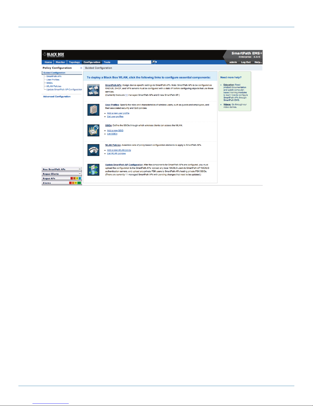
Chapter 7: Using SmartPath EMS VMA
Figure 7-9. Important sections of the SmartPath EMS VMA GUI.
Menu Bar: The items in the menu bar open the major sections of the GUI. You can then use the navigation tree to navigate to
specific topics within the selected section.
Search: This is a tool for finding a text string anywhere in the GUI (except in Reports). You can do a global search or confine a
search to a specific part of the GUI.
Log Out: Click to log out of your administrative session. If you are logged in as an admin with super user privileges and there are
virtual systems, you can exit the home system and enter a different virtual system from here.
Navigation Tree: The navigation tree contains all the topics within the GUI section that you chose in the menu bar. Items you
select in the navigation tree appear in the main panel.
Main Panel: The main panel contains the windows in which you set and view various parameters.
Notifications: SmartPath EMS VMA displays a summary of new SmartPath APs, rogue clients, rogue APs, and alarms detected on
managed SmartPath APs here. Clicking a displayed number opens the relevant page with more details.
Some convenient aspects that the SmartPath EMS VMA GUI offers are the ability to clone configurations, apply configurations to
multiple SmartPath APs at once, and sort displayed information. Brief overviews of these functions are presented in the following
sections.
7.2.1 Viewing Reports
When viewing reports that contain graphs (Monitor > Reports …), you can use your mouse to control what information
SmartPath EMS VMA displays. Moving your mouse over a measurement point on any line in a graph displays the type of data
being reported and the date, time, and value of the measurement. In the graph for active client details (Monitor > Clients > Active
Clients > client_mac_addr) or a report defined as a "New Report Version", moving your mouse over a color box in the legend
hides all other lines except the one matching that color (see Figures 7-10 and 7-11).
724-746-5500 | blackbox.com
Page 73
Page 74
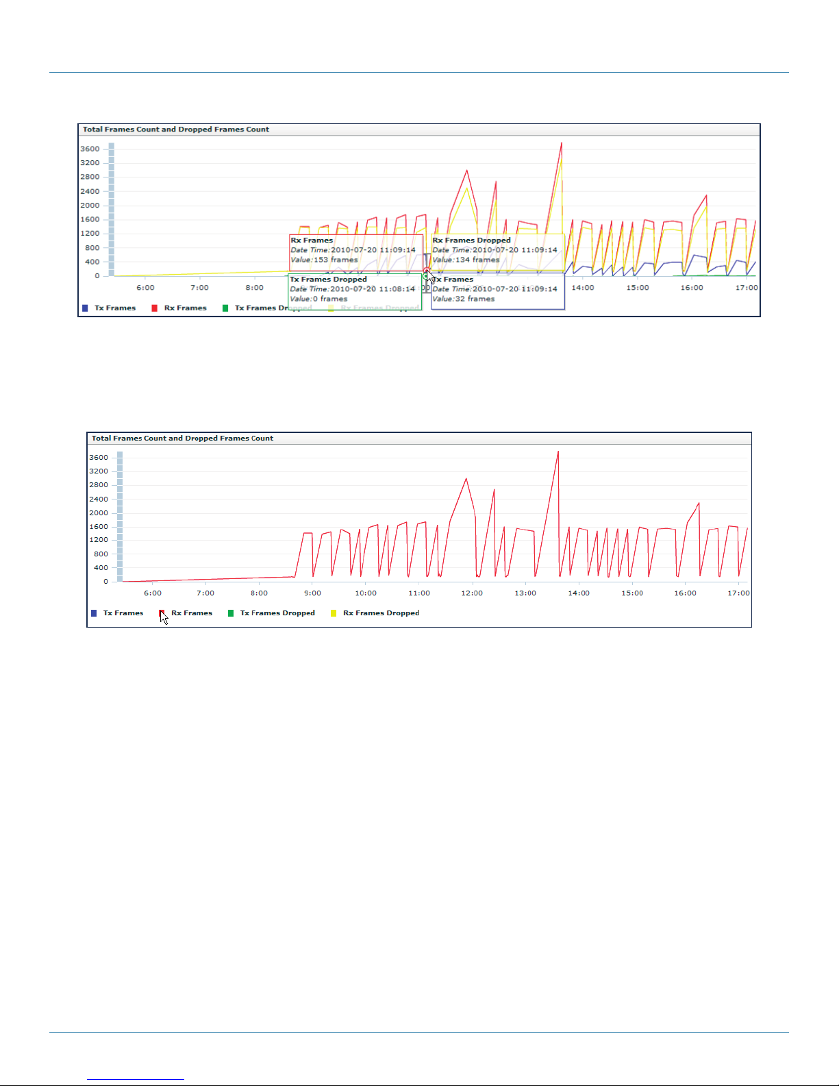
724-746-5500 | blackbox.com
Chapter 7: Using SmartPath EMS VMA
Figure 7-10. Working with graphs in reports.
Moving the mouse over a measurement point in a graph displays data about that measurement. If measurement points on multi-
ple lines happen to converge at the same point, SmartPath EMS VMA displays data for all of them. Here you can see information
about the total number of transmitted (Tx) and received (Rx) frames and dropped frames.
Figure 7-11. Working with graphs in reports.
In the graph showing details for a selected active client, moving the mouse over a colored box in the legend hides all other lines
except the one that is the same color as the box under the mouse. Here SmartPath EMS VMA only shows the red line for
transmitted frames because the mouse is over the red box next to Rx Frames in the legend.
7.2.2 CAPWAP Latency Reports
CAPWAP Latency Reports: SmartPath EMS VMA tracks the average latency in its CAPWAP connections to each managed
SmartPath AP and displays an icon indicating the average amount of current latency in the Connection column on the Monitor >
Access Points > SmartPath APs page when viewed in Monitor mode. A green hexagon indicates normal latency, based on an
average that SmartPath EMS VMA has calculated from periodic SmartPath AP reports. The icon changes to yellow when the
latency increases to the point that responsiveness has slowed noticeably; however, configuration and image uploads can still
succeed. It changes to orange when connectivity issues reach the point that configuration and image upload attempts might no
longer be successful.
Page 74
724-746-5500 | blackbox.com
Page 75
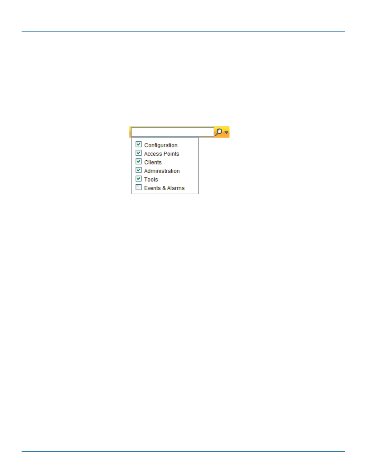
Chapter 7: Using SmartPath EMS VMA
7.2.3 Searching
The SmartPath EMS VMA GUI provides a search feature that you can use to find text strings throughout the SmartPath EMS VMA
database and the entire GUI (except in Reports and Topology) or within one or more specified sections of the GUI. By default,
SmartPath EMS VMA searches through the following sections of the GUI: Configuration, Access Points, Clients, Administration,
and Tools. You can also include Events and Alarms in your search, but not Topology. To restrict the scope of your search, click the
down arrow to the right of the search icon and select the areas of the GUI that you want to include and clear those that you
want to exclude (see Figure 7-12).
Figure 7-12. Search tool.
The following items are ignored when using the search tool:
• The names of fields in dialog boxes
• The settings on the following Home > Administration pages: SmartPath EMS VMA Settings, SmartPath EMS VMA Services, and
SPM Notification Mail List
• Certificates, captive web portal web page files, and image files
• Reports
When you enter a word or phrase in the search field and then click the Search icon—or press the Enter key on your keyboard—
SmartPath EMS VMA displays the search results in the left panel that usually contains the navigation tree. The first item in the list
is displayed in the main window. To view a different page, click the page name (see Figure 7-13).
724-746-5500 | blackbox.com
Page 75
Page 76

724-746-5500 | blackbox.com
Chapter 7: Using SmartPath EMS VMA
Figure 7-13. Search results.
NOTE: Do not use quotation marks to enclose a phrase of two or more words. Simply enter the phrase that you want to find with
spaces. See the SmartPath EMS VMA on-line Help for more information on the Search tool.
7.2.4 Multiselecting
You can select multiple objects to make the same modifications or perform the same operation to all of them at once.
Select the check boxes to select multiple noncontiguous objects, or shift-click to select check boxes for multiple contiguous
objects.
Page 76
724-746-5500 | blackbox.com
Page 77
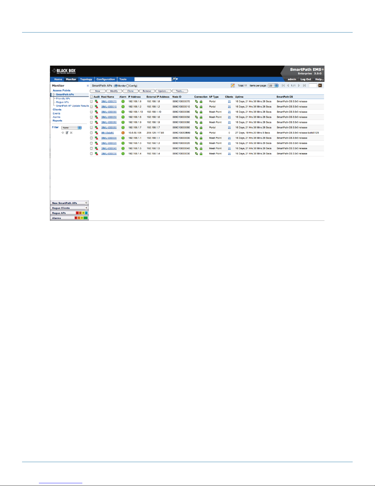
Then click the Modify button to configure them with the same settings.
Chapter 7: Using SmartPath EMS VMA
Figure 7-14. Selecting multiple new SmartPath APs.
Here, you use the shift-click multiselection method to select a set of the topmost eight SmartPath APs in the list; that is, you
select the checkbox for the top SmartPath AP and hold down the SHIFT key while selecting the checkbox for the eighth
SmartPath AP from the top.
7.2.5 Cloning Configurations
When you need to configure multiple similar objects, you can save time by configuring just the first object, cloning it, and then
making slight modifications to the subsequent objects. With this approach, you can avoid re-entering repeated data.
To clone an object, select it in an open window, and then click the Clone button. Retain the settings you want to keep, and
modify those you want to change.
724-746-5500 | blackbox.com
Page 77
Page 78
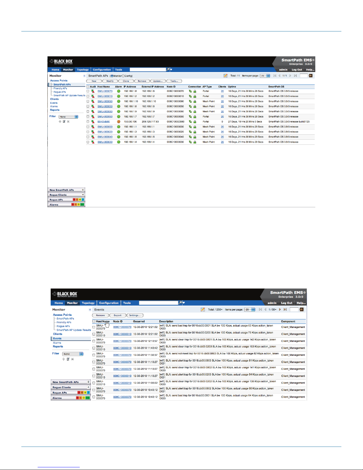
724-746-5500 | blackbox.com
Chapter 7: Using SmartPath EMS VMA
Figure 7-15. Cloning a cluster.
7.2.6 Sorting Displayed Data
You can control how the GUI displays data in the main panel by clicking a column header. This causes the displayed content to
reorder itself alphanumerically or chronologically in either ascending or descending order. Clicking the header a second time
reverses the order in which the data is displayed.
By default, displayed objects are sorted alphanumerically from the top by name. If you click the name again, the order is reversed;
that is, the objects are ordered alphanumerically from the bottom.
Figure 7-16. Sorting event log entries by SmartPath AP host name and then chronologically.
Page 78
724-746-5500 | blackbox.com
Page 79
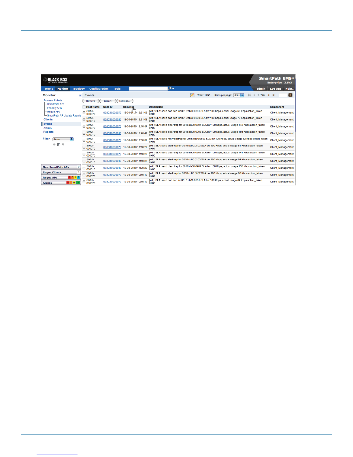
Chapter 7: Using SmartPath EMS VMA
By clicking the heading of a column, you can reorder the display of objects either alphanumerically or chronologically, depending
on the content of the selected column. Here you reorder the data chronologically.
Figure 7-17. Click to reorder the display of objects.
Indicates that the list appears in descending order from the top
Indicates that the list appears in ascending order from the bottom
7.3 SmartPath Configuration Workflow (Enterprise Mode)
Assuming that you have already set SmartPath EMS VMA in Enterprise mode and configured its basic settings, and that you have
deployed SmartPath APs, which are now connected to SmartPath EMS VMA, you can start configuring the SmartPath APs
through SmartPath EMS VMA.* You can configure numerous objects, some of which might need to reference other objects. An
efficient configuration strategy is first to define any objects that you will later need to use when configuring other objects. If one
object must reference another that has not yet been defined, there is usually a “New” button that you can click, define the object
you need, and then return to the first dialog box to continue with its configuration.
*When SmartPath APs are in the same subnet as SmartPath EMS VMA, they can use CAPWAP (Control and Provisioning of
Wireless Access Points) to discover SmartPath EMS VMA on the network. CAPWAP works within a Layer 2 broadcast domain and
is enabled by default on all SmartPath APs. If the SmartPath APs and SmartPath EMS VMA are in different subnets, then you can
use one of several approaches to enable SmartPath APs to connect to SmartPath EMS VMA. For information about these options,
see “How SmartPath APs Connect to SmartPath EMS VMA” in Section 8.4, Example 4: Connecting SmartPath APs to SmartPath
EMS VMA.
NOTE: An important initial configuration task to perform is to synchronize the internal clocks of all the managed SmartPath APs
either with the clock on SmartPath EMS VMA or with the time on an NTP server. If you plan on having the SmartPath APs
validate RADIUS, VPN, and HTTPS (captive web portal) certificates, synchronizing all the devices with the same NTP server
helps ensure synchronization.
The typical workflow proceeds like this:
1. Use default settings or configure new settings for various features that, when combined, constitute a user profile, an SSID, and
a WLAN policy. These are the three main objects that reference most of the other ones. Together these features define policies
that you can apply to multiple SmartPath APs.
724-746-5500 | blackbox.com
Page 79
Page 80

724-746-5500 | blackbox.com
Chapter 7: Using SmartPath EMS VMA
Table 7-1. Typical Workflow.
User Profile —> SSID —> WLAN P
QoS rate control and queuing User profiles SSIDs
IP firewall rules
MAC firewall rules MAC filters Management options
Captive Web portal (possibly including a
RADIUS server profile and certificates)
Cluster (possibly including MAC filters and
MAC DoS)
GRE and VPN tunnel policies Schedules
VLAN IP DoS Traffic filters
SLA (service-level agreement) settings MAC DoS VPN service
Attribute number — DNS, NTP, SNMP, syslog, location services
User manager control CTS (Clear to Send)
QoS classifier and marker maps, dynamic
airtime scheduling
Service settings for WIPS, virtual access
console, ALG services, Mgt IP filter, LLDP/ CDP
link discovery protocols, and IP tracking
2. Define various device-level configuration objects to apply to individual SmartPath APs. These include map, CAPWAP servers,
radio profiles, scheduled configuration audits, RADIUS authentication server settings, and DHCP server or DHCP relay agent
settings.
3. Apply the policy-level settings (contained within a WLAN policy) and device-level settings to one or more SmartPath APs, and
then push the configurations to physical SmartPath AP devices across the network.
LLDP Maximum Power:
To avoid SmartPath APs sending LLDP (Link Layer Discovery Protocol) transmissions requesting more power through PoE from the
connecting switch than the switch can provide, you can set a maximum power level that SmartPath APs can request in their LLDP
advertisements on the Configuration > Advanced Configuration > Network Objects > LLDP/CDP Profiles > New page. By default,
the maximum is 15.4 watts.
7.4 Updating Software on SmartPath EMS VMA
You can update the software running on SmartPath EMS VMA from either a local directory on your management system or an
SCP (Secure Copy) server. If you download an image and save it to a local directory, you can load it from there. If you save the
image to an SCP server, you can direct SmartPath EMS VMA to log in and load it from a directory there.
1. I f you do not yet have an account on the Black Box Support portal, send an e-mail request to (info@blackbox.com) to set one
up.
2. When you have login credentials, visit www.blackbox.com/support/login and log in.
3. Navigate to the software image that you want to load onto SmartPath EMS VMA (Customer Support > Software Downloads >
SmartPath EMS VMA software images) and download the file.
4. Save the SmartPath EMS VMA image file to a local directory or an SCP server.
5. Log in to SmartPath EMS VMA and navigate to Home > Administration > SmartPath EMS VMA Operations > Update Software.
6. To load files from a directory on your local management system, choose either Update and clear alarm and event logs or Full
update (to keep existing log entries after the upgrade), and then enter the following: File from local host: (select); type the
directory path and a file name; or click Browse, navigate to the software file, and select it.
or
Page 80
724-746-5500 | blackbox.com
Page 81

Chapter 7: Using SmartPath EMS VMA
To load a file from an SCP server:
File from remote server: (select)
IP Address: Enter the IP address of the SCP server.
SCP Port: Enter the port number of the SCP server (the default port number for SCP is 22).
File Path: Enter the directory path and SmartPath EMS VMA software file name. If the file is in the root directory of the SCP
server, you can simply enter the file name.
User Name: Type a user name with which SmartPath EMS VMA can access the SCP server.
Password: Type a password with which SmartPath EMS VMA can use to log in securely to the SCP server.
or
To load a file from the Black Box update server:
File from Black Box update server: (select)
A pop-up window appears with a list of newer SmartPath EMS VMA image files. If you have the latest available version, the list
will be empty. If there are newer images, select the one you want, and upgrade SmartPath EMS VMA to that image by transferring the file over an HTTPS connection from the server to SmartPath EMS VMA.
7. To save the new software and reboot SmartPath EMS VMA, click “OK.”
7.5 Updating SmartPathOS Firmware
SmartPath EMS VMA makes it easy to update SmartPathOS firmware running on managed SmartPath APs. First, you obtain new
SmartPath AP firmware from Black Box Technical Support and upload it onto SmartPath EMS VMA. Then you push the firmware
to the SmartPath APs and activate it by rebooting them.
NOTE: When upgrading both SmartPath EMS VMA software and SmartPathOS firmware, do so in this order:
• Upgrade SmartPath EMS VMA (SmartPath EMS VMA can manage SmartPath APs running the current version of
SmartPathOS and also previous versions going back two major releases).
• Upload the new SmartPathOS firmware to the managed SmartPath APs, and reboot them to activate it.
• Reload the SmartPathOS configurations to the managed SmartPath APs—even if nothing in the configurations has
changed—and reboot them to activate the configuration that is compatible with the new SmartPathOS image.
1. Log in to the Black Box SmartPath Portal to obtain a new SmartPathOS image.
2. Save the SmartPathOS image file to a directory on your local management system or network.
3. Log in to SmartPath EMS VMA and navigate to Monitor > Access Points > SmartPath APs.
4. In the SmartPath APs window, select one or more SmartPath APs, and then click “Update > Upload and Activate SmartPathOS
Software.”
The Upload and Activate SmartPathOS Software dialog box appears.
5. To the right of the SmartPathOS Image field, click “Add/Remove.”
6. In the Add/Remove SmartPathOS Image dialog box that appears, enter one of the following—depending on how you intend
to upload the SmartPathOS image file to SmartPath EMS VMA—and then click “Upload:”
To load a SmartPathOS image file from the Black Box update server:
SmartPathOS <version> images from Black Box update server: (select)
To load a SmartPathOS image file from a directory on your local management system:
Local File: (select); type the directory path and image file name, or click Browse, navigate to the image file, and select it.
724-746-5500 | blackbox.com
Page 81
Page 82

724-746-5500 | blackbox.com
Chapter 7: Using SmartPath EMS VMA
To load a SmartPathOS image file from an SCP server:
SCP Server: (select) IP Address : Enter the IP address of the SCP server.
SCP Port: Enter the port number of the SCP server (the default port number for SCP is 22).
File Path: Enter the path to the SmartPathOS image file and the file name. If the file is in the root directory of the SCP
server, you can simply enter the file name.
User Name: Type a user name with which SmartPath EMS VMA can access the SCP server.
Password: Type a password that SmartPath EMS VMA can use to log in securely to the SCP server.
NOTE: To delete an old SmartPathOS file, select the file in the "Available Images" list, and then click Remove.
7. Click Upload.
8. Close the dialog box by clicking the Close icon ( X ) in the upper right corner.
9. By default, the SmartPath EMS VMA uses SCP to transfer the file to the selected SmartPath APs and requires a manual reboot
of the SmartPath APs to activate it. If you want to change these settings, click Settings in the upper right corner of the Upload
and Activate SmartPathOS Software page.
A section expands allowing you to change how SmartPathOS images are displayed (by software version or by file name),
how the software is activated (these options are explained below), which transfer protocol to use (SCP or TFTP), the type of
connection between SmartPath EMS VMA and the SmartPath APs, and how long to wait before timing out an incomplete
update attempt.
In the Activation Time section, select one of the following options, depending on when you want to activate the firmware—by
rebooting the SmartPath APs—after SmartPath EMS VMA finishes loading it:
• Activate at: Select and set the time at which you want the SmartPath APs to activate the firmware. To use this option
accurately, make sure that both SmartPath EMS VMA and managed SmartPath AP clocks are synchronized.
• Activate after: Select to load the firmware on the selected SmartPath APs and activate it after a specified interval. The
range is 0–3600 seconds; that is, immediately to one hour. The default is 5 seconds.
• Activate at next reboot: Select to load the firmware and not activate it. The loaded firmware gets activated the next
time the SmartPath AP reboots.
NOTE: When choosing which option to use, consider how SmartPath EMS VMA connects to the SmartPath APs it is updating. See
Section 7.6.
10. To save your settings, click the Save icon in the upper right corner. Otherwise, click the Close icon to use these settings just
this time. If you do not save your modified settings, the next time you upload a SmartPathOS image to SmartPath APs,
SmartPath EMS VMA will again apply the default settings.
11. Select the file you just loaded from the SmartPath OS Image drop-down list, select one or more SmartPath APs at the bottom
of the dialog box, and then click Upload.
SmartPath EMS VMA displays the progress of the SmartPathOS image upload—and its eventual success or failure—on the
Monitor > Access Points > SmartPath AP Update Results page.
7.6 Updating SmartPath APs in a Mesh Environment
When updating cluster members in a mesh environment, be careful of the order in which the SmartPath APs reboot. If a portal
completes the upload and reboots before a mesh point beyond it completes its upload—which most likely would happen
because portals receive the uploaded content first and then forward it to mesh points—the reboot will interrupt the data transfer
to the mesh point. This can also happen if a mesh point linking SmartPath EMS VMA to another mesh point reboots before the
more distant mesh point completes its upload. As a result of such an interruption, the affected mesh point receives an incomplete
firmware or configuration file and aborts the update.
Page 82
724-746-5500 | blackbox.com
Page 83

Chapter 7: Using SmartPath EMS VMA
Switch
SmartPath AP
(Portal)
SmartPath AP
(Mesh Point 1)
SmartPath AP
(Mesh Point 2)
SmartPath EMS
NOTE: A mesh point is a cluster member that uses a wireless backhaul connection to communicate with the rest of the cluster.
SmartPath EMS VMA manages mesh points through another cluster member that acts as a portal, which links mesh points
to the wired LAN.
When updating SmartPath APs in a mesh environment, the SmartPath EMS VMA communicates with mesh points through their
portal and, if there are any intervening mesh points, through them as well. While updating SmartPath APs in such an environ-
ment, it is important to keep the path from the SmartPath EMS VMA to all SmartPath APs clear so that the data transfer along
that path is not disrupted. Therefore, when updating a firmware image or configuration on SmartPath APs in a mesh environment, make sure that the portal or a mesh point closer to the portal does not reboot before the upload to a mesh point farther
away completes.
= Wired Link
- - - - - = Wireless Link
Figure 7-18. SmartPath APs in a mesh environment.
To avoid the reboot of an intervening SmartPath AP from interfering with an ongoing upload to a mesh point beyond it, allow
enough time for the firmware to reach the farthest mesh points before activating the firmware. After all the SmartPath APs have
the firmware, rebooting any SmartPath APs between them and SmartPath EMS VMA becomes inconsequential.
724-746-5500 | blackbox.com
Page 83
Page 84

724-746-5500 | blackbox.com
Chapter 8: Basic Configuration Examples
8. Basic Configuration Examples
This chapter introduces the SmartPath EMS VMA GUI in Enterprise mode through a series of examples showing how to create a
basic configuration of an SSID, cluster, and WLAN policy. It then explains how to connect several SmartPath APs to SmartPath
EMS VMA, accept them for management, and push the configuration to them over the network.
NOTE: Although maps provide a convenient method for organizing and managing your SmartPath AP deployment, they are not
strictly required and are not covered in this chapter. For information about using maps, see Section 9.1.
You can look at any of the following examples individually to study how to configure a specific feature or view all of them
sequentially to understand the basic workflow for configuring and managing SmartPath APs through SmartPath EMS VMA.
The examples are as follows:
• Section 8.1, Example 1: Defining an SSID: Define the security and network settings that wireless clients and SmartPath APs use
to communicate.
• Section 8.2, Example 2: Creating a Cluster: Create a cluster so that the SmartPath APs can exchange information with each
other to coordinate client access, provide best-path forwarding, and enforce QoS policy.
• Section 8.3, Example 3: Creating a WLAN Policy: Define a WLAN policy, which contains the SSID and cluster defined in the first
two examples.
• Section 8.4, Example 4: Access and Backhaul on the Same Radio.
• Section 8.5, Example 5: Connecting SmartPath APs to SmartPath EMS VMA: Cable two SmartPath APs to the network to act as
portals and set up a third one as a mesh point. Put the SmartPath APs on the same subnet as SmartPath EMS VMA and allow
them to make a CAPWAP connection to SmartPath EMS VMA.
• Section 8.6, Example 6: Assigning the Configuration to SmartPath APs: Assign the WLAN policy to the SmartPath APs. Also,
change SmartPath AP login settings and—if necessary—country codes.
• Section 8.7, Example 7: Selective Multicast Forwarding through GRE Tunnels.
• Section 8.8, Example 8: IP Multicast Enhancements.
Physical devices on the network
Configuration
The conceptual relationships among the
configuration examples in this chapter.
Figure 8-1. The conceptual relationships among the configuration examples in this chapter.
In the first three examples, you define configuration objects in the Configuration section of the GUI. In the last two examples, you
connect some SmartPath APs to the network, enable them to make a CAPWAP connection to SmartPath EMS VMA, and then
manage them in the Monitor section of the GUI.
8.1 Example 1: Defining an SSID
A service set identifier (SSID) is an alphanumeric string that identifies a group of security and network settings that wireless clients
and access points use when establishing wireless communications with each other. In this example, you define the following SSID,
which uses a preshared key (PSK) for client authentication and data encryption:
SSID name: test1-psk
Page 84
724-746-5500 | blackbox.com
Page 85

Chapter 8: Basic Configuration Examples
SSID access security: WPA/WPA2 PSK (Personal)
Preshared key: CmFwbo1121
A PSK is the simplest way to provide client authentication and data encryption: simply configure an SSID with the same PSK on
the SmartPath AP and its clients. A PSK authenticates clients by the simple fact that the clients and SmartPath AP have the same
key. For data encryption, both the SmartPath AP and clients use the PSK as a pairwise master key (PMK) from which they
generate a pairwise transient key (PTK), which they use to encrypt unicast traffic. Although the PSK/PMK is the same on all
clients, the generated PTKs are different not only for each client but for each session.
Because of its simplicity, a PSK is suitable for testing and small deployments; however, there is a drawback with using PSKs on a
larger scale. All clients connecting through the same SSID use the same PSK, so if the key is compromised or a user leaves the
company, you must change the PSK on the SmartPath AP and all its clients. With a large number of clients, this can be very time-
consuming. For examples of key management solutions that are more suitable for large-scale deployments, see the 802.1X and
private PSK examples in Chapter 9. For the present goal of showing how to use SmartPath EMS VMA to configure an SSID, the
PSK method works well.
To configure the SSID, log in to the SmartPath EMS VMA GUI (see Section 7.1), click Configuration > SSIDs > New, enter the following, and then click Save:
Profile Name: test1-psk (A profile name does not support spaces, although an SSID name does.)
The profile name is the name for the entire group of settings for an SSID. It can reference a captive Web portal;
include default or modified data rate settings; apply denial of service (DoS) policies, MAC filters, and schedules;
and specify the SSID name that the SmartPath AP advertises in beacons and probe responses. The profile
name—not the SSID name (although they can both be the same)—is the one that appears in the Available
SSIDs list in the WLAN Policy dialog box. You will later choose this SSID when defining a WLAN policy in Section
8.3.
When you type in a profile name, SmartPath EMS VMA automatically fills in the SSID field with the same text
string. By default, the profile and SSID names are the same, yet they can also be different. You can create many
different SSID profiles, each with a different group of settings, but each with the same SSID name. For users,
their clients connect to the same SSID at different locations. From the SmartPath AP perspective, each SSID profile applies a different group of settings.
SSID: test1-psk
This is the SSID name that clients discover from beacons and probe responses.
Description: Test SSID for learning how to use the GUI; remove later
This note and the very name "test1-psk" are deliberately being used as reminders to replace this configuration later
with an SSID profile and SSID name that you really intend to use in your WLAN.
SSID Access Security: WPA/WPA2 PSK (Personal)
Use Default WPA/WPA2 PSK Settings: (select)
By default, when a SmartPath AP hosts a WPA/WPA2 PSK (Personal) SSID, it negotiates with clients over the use of WPA
or WPA2 for key management and TKIP or CCMP (AES) for encryption, and uses whichever methods each client supports. Also, the PSK text string is in ASCII format by default.
Key Value and Confirm Value: CmFwbo1121 (To see the text strings that you enter, clear the Obscure Password checkbox.)
With these settings, the SmartPath AP and its clients can use either WPA or WPA2 for key management, CCMP (AES) or
TKIP for data encryption, and the preshared key "CmFwbo1121" as the pairwise master key from which they each
generate pairwise transient keys.
Enable Captive Web Portal: (clear)
724-746-5500 | blackbox.com
Page 85
Page 86

724-746-5500 | blackbox.com
Chapter 8: Basic Configuration Examples
Beacons
Client
SSID: test1-psk
Key method: WPA-PSK or WPA2-PSK
Encryption: CCMP (AES) or TKIP
Supported rates and capabilities
The SmartPath AP broadcasts beacons advertising
the SSID “test1-psk” and its security and network
capabilities on the 2.4 GHz band.
If the client sends a probe request to discover
available SSIDs, the SmartPath AP responds with
the same information as that in its beacons.
The client sends an authentication request, and
because WPA and WPA2 use open authentication,
the response always accepts the request.
The client sends its capabilities, and the SmartPath AP
replies if these are acceptable or not. If they are, it
creates an association ID and sends it to the client.
The SmartPath AP and client exchange the preshared
key and other information to derive keys to encrypt
unicast traffic. (Later, they derive encryption keys for
multicast and broadcast traffic as well.)
Beacons
Probe Request
Probe Response
Authentication Request
Authentication Response
Association Request
Association Response
Four-Way Handshake
SmartPath AP
Enable MAC Authentication: (clear)
User profile assigned to users that associate with this SSID: default-profile
The predefined user profile "default-profile" applies the standard SmartPath Quality of Service level through the
predefined QoS policy "def-user-qos" and assigns user traffic to VLAN 1.
SSID Broadcast Band: 2.4 GHz (11n/b/g)
SmartPath APs have two radios: a 2.4-GHz radio, which supports 802.11n/b/g, and a 5-GHz radio, which supports
802.11n/a. On all SmartPath AP models, both radios can function concurrently. This setting broadcasts the SSID on the
wifi0 interface, which is bound to the 2.4-GHz radio. (There is an assumption that your clients support at least one of the
following IEEE standards: 802.11n, 802.11g, or 802.11b.)
As will be seen later in this chapter, one SmartPath AP will be deployed as a mesh point; that is, it will not have an
Ethernet connection but will connect to the wired network over a wireless backhaul link through another SmartPath AP
that does have an Ethernet connection (see Section 8.5). Because of this, the SmartPath APs must use one radio for
wireless backhaul communications and the other radio for client access. By default, both the 2.4-GHz and 5-GHz radios
are in access mode.
In the series of examples in this chapter, you set the 5-GHz radio in backhaul mode, and the 2.4-GHz radio in access
mode. Therefore, you assign the SSID to the 2.4-GHz band.
To see how the different SSID settings determine the way that the SmartPath AP advertises the SSID and how clients form
associations with it, see Figure 8-2.
Figure 8-2. How a client discovers the SSID and forms a secure association.
Page 86
724-746-5500 | blackbox.com
Page 87

Chapter 8: Basic Configuration Examples
8.2 Example 2: Creating a Cluster
A cluster is a group of SmartPath APs that exchanges information with each other to form a collaborative whole. Through
coordinated actions based on shared information, cluster members can provide the following services:
• Consistent Quality of Service (QoS) policy enforcement across all cluster members
• Coordinated and predictive wireless access control that provides seamless Layer 2 and Layer 3 roaming to clients moving from
one cluster member to another (The members of a cluster can be in the same subnet or different subnets, allowing clients to
roam across subnet boundaries.)
• Dynamic best-path routing for optimized data forwarding and network path redundancy
• Automatic radio frequency and power selection for wireless mesh and access radios
• Tunneling of client traffic from one cluster member to another, such as the tunneling of guest traffic from a SmartPath AP in the
internal network to another SmartPath AP in the corporate DMZ
Cluster members use Wi-Fi Protected Access with a preshared key (WPA-PSK) to exchange keys and secure wireless cluster
communications. To authenticate and encrypt wireless cluster communications, cluster members use open authentication and
CCMP (AES) encryption. CCMP is a rough acronym for "Counter Mode with Cipher Block Chaining Message Authentication Code
Protocol" that makes use of Advanced Encryption Standard (AES). This is very similar to the security provided by the SSID in the
preceding example.
In this example, you define a cluster and name it "cluster-test1". Later, in Section 8.3, you assign the cluster to a WLAN policy,
which in turn, you assign to SmartPath AP devices in Section 8.5.
NOTE: A WLAN policy is different from a cluster. Unlike the members of a WLAN policy who share a set of policy-based
configurations, the members of a cluster communicate with each other and coordinate their activities as access points.
WLAN policy members share configurations. Cluster members work together collaboratively.
Click Configuration > Advanced Configuration > Clusters > New, enter the following, leave the other options at their default
settings, and then click Save:
Cluster: cluster1-test (You cannot include spaces in the name of a cluster.)
Description: Test cluster for learning how to use the GUI; remove later
As was done in the previous example, this note and the name "cluster1-test" are intended to act as reminders to replace
this configuration later with a cluster name that you really intend to use.
Modify Encryption Protection: (select)
Automatically generate password: (select)
The password is what cluster members use when authenticating themselves to each other over the wireless backhaul link
using WPA-PSK CCMP (AES). As an admin, you never need to see or know what this string is; therefore, using the
automatic password generation method saves you the trouble of inventing a long—up to 63 characters—and random
alphanumeric string.
Optional Settings: Leave the optional settings as they are by default. For information about these settings, and about any setting
in the GUI for that matter, see the SmartPath EMS VMA on-line Help system.
8.3 Example 3: Creating a WLAN Policy
Through SmartPath EMS VMA, you can configure two broad types of features:
• Policy-level features—In combination, these features form policies that control how users access the network: SSIDs, user
profiles, QoS forwarding mechanisms and rates, clusters, AAA (authentication, authorization, accounting) services, management
services (DNS, NTP, SNMP, and syslog), tunnel policies, IP and MAC firewall policies, and VLAN assignments.
724-746-5500 | blackbox.com
Page 87
Page 88

724-746-5500 | blackbox.com
Chapter 8: Basic Configuration Examples
• Device-level features—These features control how cluster members communicate with the network and how radios operate in
different modes, frequencies, and signal strengths.
A WLAN policy is an assembly of policy-level feature configurations that SmartPath EMS VMA pushes to all SmartPath APs that
you assign to the policy. Because these configurations are policy-based, they can apply across multiple physical devices. In contrast, device-level configurations are more appropriately applied to smaller sets of devices or to individual devices themselves.
In this example, you create a WLAN policy that includes the SSID and cluster configured in the previous two examples. Although
the New WLAN Policy dialog box consists of several pages, for this basic configuration, you only need to configure items on the
first page (see Figure 8-3).
Click Configuration > WLAN Policies > New, enter the following on the first page of the new WLAN policy dialog box, leave all
the other settings as they are, and then click Save:
Name: wlan-policy-test1 (You cannot use spaces in the WLAN policy name.)
Description: Test WLAN policy for learning how to use the GUI; remove later
Cluster: cluster1-test (The cluster was previously configured in “Example 2: Creating a Cluster” in Section 8.2.)
SSID Profiles: Click Add/Remove SSID Profile, choose test1-psk in the Available SSID Profiles list, click the right arrow ( > ) to
move it to the Selected SSID Profiles list, and then click Apply. (The SSID was previously configured in Section 8.1.)
The creation of a WLAN policy that puts the SmartPath APs to which you apply it in a cluster and provides them with an SSID is
complete. In the following examples, you deploy several SmartPath APs on a network, accept them for SmartPath EMS VMA
management, and then apply the WLAN policy to them.
Page 88
Figure 8-3. WLAN policy general settings.
724-746-5500 | blackbox.com
Page 89

Chapter 8: Basic Configuration Examples
8.4 Example 4: Access and Backhaul on the Same Radio
Black Box SmartPath APs have the ability to provide both wireless client access and backhaul services on the same interface. When
you configure a SmartPath AP mesh point to operate in this way, you create a redundant pathway if one of the interfaces fails.
This capability allows single radio SmartPath APs to operate as a mesh point with client access abilities, which was not possible
previously.
Mesh Failover Overview
Mesh failover is the process by which a SmartPath AP maintains a network connection if the physical Ethernet connection is lost.
SmartPath APs constantly check the health of the Ethernet connection and begin scanning for a SmartPath AP with which to form
a mesh link using ACSP (Advanced Channel Selection Protocol). For mesh failover to occur, both client access and mesh communications must be possible simultaneously. If wifi0 is in access mode and wifi1 is in either backhaul or dual mode (access and backhaul, see below), then the SmartPath AP selects the wifi1 interface to form the mesh link.
NOTE: There are two places in the GUI that affect mesh failover: the backhaul failover settings in the specified radio profile and
the radio mode settings for the SmartPath AP. To enable backhaul failover, it must be enabled in the radio profile and the
radio must be in either backhaul or dual mode. (Backhaul mode provides a mesh link to another SmartPath AP. Dual mode
provides both client access and backhaul mesh link on the same radio.)
See the following table for how these settings affect failover ability and client support.
Table 8-1. Failover ability and client support.
SmartPath AP Radio Service Settings Services Clients on Both Bands Provides Mesh Link Failover
Use both radios for client access Yes No
Use radio (2.4 GHz) for client access, radio (5 GHz) for a mesh link No No
Use radio (2.4 GHz) for client access, radio (5 GHz) for client access,
radio (5 GHz) for client access and a mesh link (default setting)
Yes Yes
The following illustration provides an overview of how the failover occurs. Three SmartPath APs are connected to an Ethernet
backhaul, and each has clients on both the wifi0 and wifi1 interfaces on the channels and in the modes shown:
724-746-5500 | blackbox.com
Page 89
Page 90

724-746-5500 | blackbox.com
Chapter 8: Basic Configuration Examples
Wired Ethernet
Backhaul
SmartPath AP loses its Ethernet
connectivity. SmartPathOS 4.0
detects the failure and begins
scanning on wifi1 for the best
neighbor.
All SmartPath APs:
wifi0 = access
wifi1 = dual
(default settings)
SmartPath AP judges signal conditions
and determines that SmartPath AP 3 has
the best signal quality. SmartPath AP 2
changes its channel to match that of
SmartPath AP 3, and establishes a mesh
link on Channel 161.
To configure a SmartPath AP to use access and backhaul simultaneously:
Click Monitor > Access Points > SmartPath APs, select the check box next to the SmartPath AP you want to configure, click
“Modify,” select the “Use radio (2.4 GHz) for client access, radio (5 GHz) for client access as well as a mesh link radio,” and then
click “Save.”
Page 90
Figure 8-4. Overview of failover.
724-746-5500 | blackbox.com
Page 91

Chapter 8: Basic Configuration Examples
= Wired Link
= Wireless Link
SmartPath EMS VMA
Single Subnet
Layer-2 Broadcasting Domain
Router/Firewall/DHCP Server
Switch/PSE The switch delivers power to
SmartPath AP1 and SmartPath AP2 through PoE.
SmartPath AP1
(Portal)
SmartPath AP3
(Mesh Point)
SmartPath AP3 receives power
from a 100-240 VAC outlet.
SmartPath AP2
(Portal)
Figure 8-5. Select radio.
By selecting the Enable the bridging of Ethernet connection devices over the wireless mesh network checkbox, you enable
advanced bridging features, such as bridge-access and bridge-802.1Q modes. To configure these modes, click Optional Settings >
Interface and Network Settings.
8.5 Example 5: Connecting SmartPath APs to SmartPath EMS VMA
In this example, you set up three SmartPath APs for management through SmartPath EMS VMA. Cable two of the SmartPath
APs—SmartPath AP1 and SmartPath AP2—to the network. Run an Ethernet cable from the eth0 port on each SmartPath AP to a
switch so that they are in the same subnet as the IP address of the MGT interface on SmartPath EMS VMA. (Neither the
SmartPath AP 300 eth1 port nor the SmartPath EMS VMA LAN port are used in this example.) You can use AC/DC power adapters to connect them to a 100–240 VAC power source or allow them to obtain power through PoE from PSE on the network.
(Both power adapters and PoE injectors are available from Black Box as options.) Place the third SmartPath AP—SmartPath AP3—
within range of the other two, and use a power adapter to connect it to an AC power source. See Figure 8-6, in which the switch
uses PoE to provide power to SmartPath APs 1 and 2.
By default, the SmartPath APs obtain their network settings dynamically from a DHCP server. SmartPath AP3 reaches the DHCP
server after first forming a wireless link with the other two SmartPath APs. (A SmartPath AP in the position of SmartPath AP3 is
Figure 8-6. Connecting SmartPath APs to the network.
referred to as a mesh point, and SmartPath APs such as SmartPath AP1 and 2 are called portals.)
Within the framework of the CAPWAP protocol, SmartPath APs act as CAPWAP clients and SmartPath EMS VMA as a CAPWAP
server. Because all devices are in the same subnet in this example, the clients can broadcast CAPWAP Discovery Request messages
to discover and establish a secure connection with the server automatically. During the connection process, each client proceeds
through a series of CAPWAP states, resulting in the establishment of a secure Datagram Transport Layer Security (DTLS)
connection. These states and the basic events that trigger the client to transition from one state to another are shown
in Figure 8-7.
SmartPath AP3 receives power from a
100–240 VAC outlet.
724-746-5500 | blackbox.com
Page 91
Page 92

724-746-5500 | blackbox.com
Chapter 8: Basic Configuration Examples
NOTE: To illustrate all possible CAPWAP states, Figure 8-5 begins by showing a SmartPath AP and SmartPath EMS VMA already in
the Run state. When a SmartPath AP first attempts to discover a SmartPath EMS VMA—after the SmartPath AP has an IP
address for its mgt0 interface and has discovered or has been configured with the SmartPath EMS VMA IP address—it
begins in the Discovery state.
For information about various ways that SmartPath APs can form a secure CAPWAP connection with a physical SmartPath EMS
VMA appliance or a SmartPath EMS VMA Virtual Appliance in the same or different subnets, and with SmartPath EMS Online,
see “How SmartPath APs Connect to SmartPath EMS VMA” in this section.
Page 92
724-746-5500 | blackbox.com
Page 93
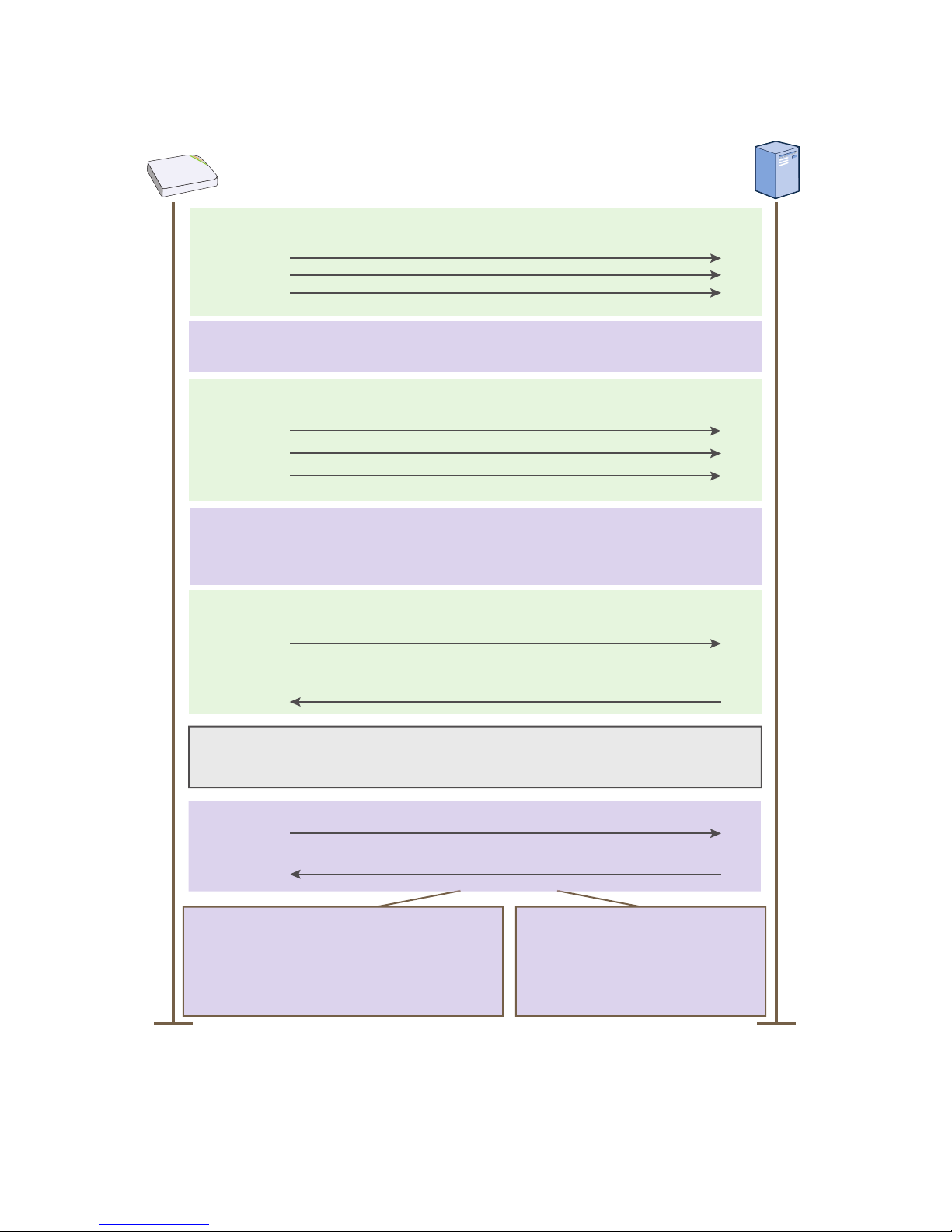
Chapter 8: Basic Configuration Examples
The CAPWAP client (SmartPath AP) pings the CAPWAP server (SmartPath
EMS VMA) but receives no responses within the neighbor-dead-interval.
The client transitions to the Discovery state and begins sending
Discovery Request messages (broadcast or unicast).
If the client continues to send Discovery Request messages until it
reaches the max-discovery-interval and max-discovery-count but
receives no Discovery Responses, the client then enters the Sulking
state and remains in this state until the silent-interval elapses.
CAPWAP Client
(SmartPath AP)
CAPWAP Server
(SmartPath EMS VMA)
Discovery
State
The CAPWAP client returns to the Discovery state and sends
Discovery Request messages.
The CAPWAP server receives the Discovery Request message
and responds with a Discovery Response.
Discovery
State
Sulking
State
The client sends a Join Request.
Join
State
. . .
. . .
Run
State
Idle
State
When the client determines its neighbor is dead, it transitions
from the Run state to the Idle state.
The CAPWAP client and server perform a DTLS (Datagram Transport
Layer Security) handshake to establish a secure DTLS connection.
The server sends a Join Response.
If the Join Response indicates “success”, the client
clears its WaitJoin timer and enters the Run state.
Note: If the WaitJoin timer expires before the client
receives a successful Join Response, the client
terminates the DTLS connection and returns to the
Discover state.
If the Join Response indicates “failure”,
the CAPWAP server enters a Reset
state and terminates the DTLS session.
Check that the SmartPath APs have made a CAPWAP connection with SmartPath EMS VMA:
Click “Monitor > Access Points > SmartPath APs.”
Figure 8-7. CAPWAP Connection process—beginning from the run state.
724-746-5500 | blackbox.com
Page 93
Page 94

724-746-5500 | blackbox.com
Chapter 8: Basic Configuration Examples
The page displays the three SmartPath APs that you put on the network. If you see the three SmartPath APs, refer to Figure 8-6.
If you do not see them, check the following:
• Do the SmartPath APs have power?
Check the PWR (Power) status LED on the top of the devices. If it is glowing steady green, it has power and has finished boot-
ing up. If the PWR status LED on a SmartPath AP (LWN602HA) is pulsing green, it is still loading the SmartPathOS firmware. If
the PWR status LED is dark, the device does not have power. If a SmartPath AP is getting power through PoE from the switch
or from a power injector, make sure that the PSE is configured and cabled correctly. If a SmartPath AP is powered from an AC
outlet, make sure that the power cable is firmly attached to the power connector, the AC/DC power adapter, and the outlet.
• Are the two portals—SmartPath AP1 and SmartPath AP2—connected to the Ethernet network?
When the devices are properly connected, the ETH0 status LED on the SmartPath AP (LWN602HA) pulses green to indicate a
1000-Mbps link or amber for a 10-/100-Mbps link. If the ETH0 is dark, make sure that both ends of the Ethernet cable are
fully seated in the SmartPath AP and switch ports. If the ETH0 status LED is still dark, try a different cable.
• Did the SmartPath APs receive network settings from a DHCP server? At a minimum, each SmartPath AP needs to receive an IP
address, netmask, and default gateway in the same subnet as SmartPath EMS VMA. To check their settings, make a physical or
virtual console connection to the SmartPath APs,* and do the following:
To check the IP address, netmask, and default gateway of the mgt0 interface on a SmartPath AP, enter show interface mgt0,
and look at the settings displayed in the output.
* To make a physical console connection, connect a console cable to the SmartPath AP as explained in Chapter 5 (the SmartPath
AP platform chapter). A virtual access console is an SSID that the SmartPath AP automatically makes available for administrative
access when it does not yet have a configuration and cannot reach its default gateway. By default, the SSID name is “<hostname>_ac”. Form a wireless association with the SmartPath AP through this SSID, check the IP address of the default gateway
that the SmartPath AP assigns to your wireless client, and then make an SSH or Telnet connection to the SmartPath AP at that IP
address. When you first connect, the Initial CLI Configuration Wizard appears. Because you do need to configure all the settings
presented in the wizard, enter N to cancel it. When prompted to log in, enter the default admin name: BB-(last six digits of MAC
address) (for example, BB-123456) and password: blackbox. For SmartPath APs set with "world" as the region code, enter the
boot-param country-code number command. For number, enter the country code for the location where you intend to deploy the
SmartPath AP. For a list of country codes, see Appendix: Country Codes.
A mesh point must first establish a wireless link to a portal over their backhaul interfaces before it can contact a DHCP server.
To see that the mesh point (SmartPath AP3) has successfully formed a link with a portal using the default cluster "cluster0",
enter show cluster cluster0 neighbor and check the Cstate column. If at least one other SmartPath AP is listed as a neighbor
and its cluster state is Auth, the mesh point has successfully formed a link and can access the network. If the cluster state is
anything else, it might still be in the process of forming a link. The following are the various cluster states:
Disv (Discover)—Another SmartPath AP has been discovered, but there is a mismatch with its cluster ID.
Neibor (Neighbor)—Another SmartPath AP has been discovered whose cluster ID matches, but it has not yet been
authenticated.
CandPr (Candidate Peer)—The cluster ID on a discovered SmartPath AP matches, and it can accept more neighbors.
AssocPd (Association Pending)—A SmartPath AP is on the same backhaul channel, and an association process in
progress.
Assocd (Associated) —A SmartPath AP has associated with the local SmartPath AP and can now start the authentication
process.
Auth (Authenticated)—The SmartPath AP has been authenticated and can now exchange data traffic. You can also
check the presence of cluster neighbors by viewing the entries listed in the Supplicant column for the wifi1.1 interface in
the output of the show auth command.
Page 94
724-746-5500 | blackbox.com
Page 95
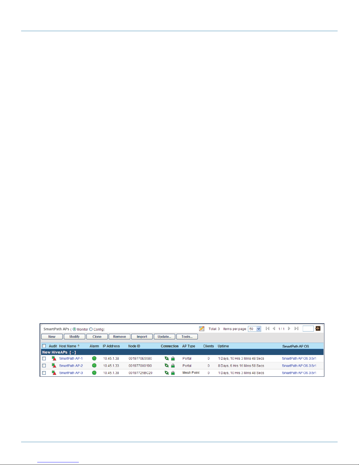
Chapter 8: Basic Configuration Examples
If the SmartPath AP does not have any network settings, check that it can reach the DHCP server. To check if a DHCP
server is accessible, enter interface mgt0 dhcp-probe vlan-range <number1> <number2>, in which <number1> and
<number2> indicate the range of VLAN IDs on which you want the SmartPath AP to probe for DHCP servers. The results
of this probe indicate if a DHCP server is present and has responded. If the probe succeeds, check the DHCP server for
MAC address filters or any other settings that might interfere with delivery of network settings to the SmartPath AP.
• Are the SmartPath APs in the same subnet as SmartPath EMS VMA?
SmartPath APs must be in the same subnet and the same VLAN as SmartPath EMS VMA for their broadcast CAPWAP Discovery
messages to reach it. If you can move the SmartPath APs or SmartPath EMS VMA so that they are all in the same subnet, do so.
If they must be in different subnets from each other, it is still possible for the SmartPath APs to contact SmartPath EMS VMA,
but not by broadcasting CAPWAP messages. For a list of other connection options, see "How SmartPath APs Connect to
SmartPath EMS VMA" on the next page.
• Can the SmartPath APs ping the IP address of the SmartPath EMS VMA MGT interface?
Enter the ping <ip_addr> command on the SmartPath AP, where the variable <ip_addr> is the IP address of the SmartPath EMS
VMA MGT interface. If it does not elicit any ICMP echo replies from SmartPath EMS VMA, make sure that SmartPath EMS VMA
is connected to the network through its MGT interface, not its LAN interface, and that the IP address settings for the MGT
interface are accurate (see SP Admin > SmartPath EMS VMA Settings > Interface Settings in the SmartPath EMS VMA GUI).
• What is the status of the CAPWAP client running on the SmartPath AP?
To check the CAPWAP status of a SmartPath AP, enter the show capwap client command. Compare the "RUN state" with the
CAPWAP states explained in Figure 8-5. Check that the SmartPath AP has an IP address for itself and the correct address for
SmartPath EMS VMA. If for some reason, the SmartPath AP does not have the correct address for SmartPath EMS VMA, you
can set it manually by entering the capwap client server name <ip_addr> command, in which <ip_addr> is the SmartPath EMS
VMA MGT interface IP address.
When SmartPath APs have contacted SmartPath EMS VMA, they appear in the Monitor > Access Points > SmartPath APs page, as
shown in Figure 8-8.
Audit icons:
Green square + red triangle: The
configuration on a SmartPath AP
does not match that on the
SmartPath EMS VMA.
Two green squares: they match.
CAPWAP connection and security icons:
Green linked chain/red unlinked chain: The
SmartPath AP is connected or disconnected.
Green locked padlock/red unlocked padlock:
Connection is secured through DTLS or not.
You can customize the table contents
by clicking the Edit Table icon. You can
add more columns (radio channels and
power, for example), remove columns,
and reorder them.
The host names have been changed
to match those in the example.
By default, the host name is BB- +
the last six bytes of its MAC address.
(Example: BB-0E5580)
Figure 8-8. Monitor > Access Points > SmartPath APs (view mode: Monitor).
The AP type for SmartPath AP1 and SmartPath
AP2 is “Portal.” They have Ethernet connections
to the network. SmartPath AP3 is the “Mesh
Point.” It connects to the network through a
portal.
724-746-5500 | blackbox.com
Page 95
Page 96

724-746-5500 | blackbox.com
Chapter 8: Basic Configuration Examples
NOTE: If you see a different group of SmartPath AP settings, make sure that Monitor is selected as the view mode at the top of
the SmartPath APs page. The GUI provides two view modes for SmartPath APs, one that focuses on monitoring SmartPath
APs (Monitor) and another that focuses on configuring them (Config).
How SmartPath APs Connect to SmartPath EMS VMA
SmartPath APs and SmartPath EMS communicate with one another through CAPWAP (Control and Provisioning of Wireless
Access Points). SmartPath APs act as CAPWAP clients and SmartPath EMS acts as a CAPWAP server. SmartPath APs can form a
CAPWAP connection with SmartPath EMS in any of the following ways:
• When SmartPath APs are in the same layer 2 broadcast domain as a SmartPath EMS appliance or SmartPath EMS VMA Virtual
Appliance, the SmartPath APs broadcast CAPWAP Discovery Request messages to discover SmartPath EMS and establish a
secure connection with it automatically.
• If there is no SmartPath EMS VMA in the same broadcast domain but the SmartPath APs can reach the SmartPath EMS Online
redirector—and serial number entries for the SmartPath APs have already been added to the SmartPath EMS Online ACL (access
control list)—then they can form secure CAPWAP connections with the redirector (redirection server). From there, an adminis-
trator can assign the connected SmartPath APs to a SmartPath EMS VMA (virtual management appliance) at the cluster site or
to a SmartPath EMS VMA appliance—virtual or otherwise—at another site.
• Finally, SmartPath APs and a local SmartPath EMS VMA might be in different subnets and the SmartPath APs either cannot
reach SmartPath EMS Online or they can but they are not listed in the ACL (perhaps because they are not included in any
SmartPath EMS Online account). In this case, the SmartPath APs cannot discover SmartPath EMS by broadcasting CAPWAP
Discovery Request messages, nor can they reach the redirector. So that the SmartPath APS can form a CAPWAP connection to
SmartPath EMS, you can use one of the following methods to configure them with the SmartPath EMS VMA domain name or
IP address or configure them so that they can learn it through DHCP or DNS settings. When SmartPath APs have the IP address
of the CAPWAP server, they then send unicast CAPWAP Discovery Request messages to that address.
• Log in to the CLI on the SmartPath AP and enter the IP address or domain name of the CAPWAP server:
capwap client server name <string>
• Configure the DHCP server to supply the SmartPath EMS VMA domain name as DHCP option 225 or its IP address as option
226 in its DHCPOFFER. (If you use a domain name, the authoritative DNS server for that domain must also be configured with
an A record that maps the domain name to the SmartPath EMS VMA IP address.) A SmartPath AP requests options 225 and
226 by default when it broadcasts DHCPDISCOVER and DHCPREQUEST messages.
NOTE: If you need to change the DHCP option number (perhaps because another custom option with that number is already in
use on the DHCP server), enter this command with a different option number:
interface mgt0 dhcp client option custom clustermanager <number> { ip | string }
• If SmartPath EMS VMA continues to use its default domain name (“smartpathemsvma”) plus the name of the local domain to
which it and the SmartPath APs belong, configure an authoritative DNS server with an A record that resolves
"clustermanager.<local_domain>" to an IP address. If a SmartPath AP does not have an IP address or domain name configured
for the CAPWAP server and does not receive an address or a domain name returned in a DHCP option, then it tries to resolve
the domain name to an IP address.
If you are using SmartPath EMS Online instead of a physical SmartPath EMS VMA appliance or SmartPath EMS VMA Virtual
Appliance and the SmartPath APs go on-line for the first time without any specific CAPWAP server configuration entered manually or received as a DHCP option, they progress through the following cycle of CAPWAP connection attempts. First, they try to
connect with a CAPWAP server at clustermanager.<local_domain>. If that is unsuccessful, they next try to elicit a response from
the broadcast of CAPWAP Discovery messages on their local subnet. If neither of these efforts produces a response, they try to
connect to SmartPath EMS Online, first using the CAPWAP UDP port 12222 and then using CAPWAP over the HTTP TCP port of
80. This cycle is shown in Figure 8-9.
Page 96
724-746-5500 | blackbox.com
Page 97

Chapter 8: Basic Configuration Examples
SmartPath EMS VMA
SmartPath EMS
VMA Online
1
2
3
4
If the DNS server cannot resolve
the domain name to an IP
address, the SmartPath AP
broadcasts CAPWAP Discovery
messages on its local subnet for
a CAPWAP server (SmartPath
EMS VMA). If SmartPath EMS
VMA is on the local network and
responds, they form a secure
CAPWAP connection.
The SmartPath AP tries to connect to
SmartPath EMS VMA using the following
default domain name:
smartpathemsvma<local_domain>, where
“<local_domain>” is the domain
name that a DHCP server
supplied to the SmartPath AP. If
a DNS server has been
configured with an A record to
resolve that domain name to an
IP address, the SmartPath AP
and SmartPath EMS VMA then
form a secure CAPWAP
connection.
If the first two searches for a
local SmartPath EMS VMA
produce no results, the
SmartPath AP broadens its
search even wider and tries to
contact SmartPath EMS VMA
Online at
staging.blackbox.com:12222. If
the staging server has a serial
number or MAC address for that
SmartPath AP, it responds and
they form a secure CAPWAP
connection.
If the SmartPath AP cannot
make a CAPWAP connection
to SmartPath EMS VMA Online
using UDP port 12222, it tries to
reach it by using TCP port 80:
staging.blackbox.com:80.
If that proves unsuccessful,
the SmartPath AP returns to
its initial search through a DNS
lookup and repeats the cycle.
1. If the DNS server cannot resolve the domain name to an IP address, the SmartPath AP broadcasts CAPWAP Discovery messages
on its local subnet for a CAPWAP server (SmartPath EMS VMA). If SmartPath EMS VMA is on the local network and responds,
they form a secure CAPWAP connection.
The SmartPath AP tries to connect to SmartPath EMS VMA using the following default domain name: smartpathEMS.<local_
domain>,
where “<local_domain>” is the domain name that a DHCP server supplied to the SmartPath AP.
If a DNS server has been configured with an A record to resolve that domain name to an IP address, the SmartPath AP and
SmartPath EMS VMA then form a secure CAPWAP connection.
If the first two searches for a local SmartPath EMS VMA produce no results, the SmartPath AP broadens its search even wider and
tries to contact SmartPath EMS Online at SmartPath.blackbox.com:12222. If the online server has a serial number or MAC address
for that SmartPath AP, it responds and they form a secure CAPWAP connection.
If the SmartPath AP cannot make a CAPWAP connection to SmartPath EMS Online using UDP Port 12222, it tries to reach it by
using TCP Port 80:smartpath.blackbox.com:80. If that proves unsuccessful, the SmartPath AP returns to its initial search through a
DNS lookup and repeats the cycle.
8.6 Example 6: Assigning the Configuration to SmartPath APs
After completing the steps in the previous examples, you now assign the WLAN policy to the SmartPath APs. In addition, you set
one radio in access mode and one in backhaul mode, and you change their login settings (and country code if necessary).
Finally, you push the configuration to the SmartPath APs. The transfer of SmartPath AP configuration assignments is presented
conceptually in Figure 8-10.
Figure 8-9. Discovering the CAPWAP server.
724-746-5500 | blackbox.com
Page 97
Page 98

724-746-5500 | blackbox.com
Chapter 8: Basic Configuration Examples
CAPWAP traffic secured with DTLS
Note: The CAPWAP path to SmartPath AP3 really passes
through one of the portals (SmartPath AP1 or
SmartPathAP2) before reaching it.
SmartPath EMS VMA
Members of “cluster1-test”
SmartPath AP3
(Mesh Point)
SmartPath AP2
(Portal)
SmartPath AP1
(Portal)
WLAN Policy:
wlan-policy-test1
SSID: test1-psk
Cluster: cluster1-test
DHCP client: enabled
Credentials:
Name: testadmin1
Password: testpass1
SSID: test1-psk
Cluster: cluster1-test
DHCP client: enabled
Credentials:
Name: testadmin1
Password: testpass1
Figure 8-10. SmartPath AP configuration assignments.
Assigning Configurations
Members of “cluster 1 test”
1. Click “Monitor > Access Points > SmartPath APs (View mode: Config).”
2. Because you can only set radio modes on individual SmartPath APs, click one of their names, select Use one radio (2.4 GHz) for
client access and one radio (5 GHz) for a mesh link, and then click Save. Repeat this step for all the other SmartPath APs as
well.
3. To modify all the SmartPath APs at the same time, select the checkbox in the header to the left of Host Name, which selects
the checkboxes of all the SmartPath APs, and then click “Modify.”
The SmartPath APs > Modify (Multiple) dialog box appears.
4. From the WLAN Policy drop-down list, choose wlan-policy-test1. This is the WLAN policy that you created in Section 8.3. Do
not modify any of the other basic settings.
5. In the Optional Settings section, expand Credentials, and then enter the following in the Root Admin Configuration section:
New Admin Name: testadmin1
This is the root admin name that SmartPath EMS VMA uses to make SSH connections and upload a full configuration to
managed SmartPath APs. The default root admin name and password is admin and blackbox.
New Password: testpass1
Confirm New Password: testpass1
Although changing the login credentials is not necessary, it is good practice, which is why it is included here. When you
NOTE: To see the text strings that you enter, clear the Obscure Password check box.
6. Leave the other settings as they are, and then click Save to save your configuration and close the dialog box.
7. Check your settings in the SmartPath APs window (see Figure 8-11).
are ready to deploy the SmartPath APs on your network, change the admin name and password again.
Page 98
724-746-5500 | blackbox.com
Page 99

Chapter 8: Basic Configuration Examples
Figure 8-11. Monitor > Access Points > SmartPath APs (view mode: Config).
Updating the Country Code
For SmartPath APs intended for use in the United States, the region code is preset as "FCC"—for "Federal Communications
Commission"—and the country code is preset as "United States". If this is the case, you can skip this section.
If the preset region code for the managed SmartPath APs is "World", you must set the appropriate country code to control the
radio channel and power selections that SmartPath APs can use. If this is the case, set the country code as follows:
1. On the Monitor > Access Points > SmartPath APs page, select the checkbox for SmartPath AP3, and then click Update >
Update Country Code.*
*When updating the country code on SmartPath APs in a mesh environment, you do not want the rebooting of portals to
interrupt the data path between the SmartPath EMS VMA and mesh points before they can complete their update process.
Therefore, try to update and reboot mesh points first. Then, update and reboot the portals. See Section 7.6.
2. In the Update Country Code dialog box, enter the following, and then click Upload:
• Choose the country where they are deployed from the New Country Code drop-down list.
NOTE: Be sure to choose the correct country. An incorrect choice might result in illegal radio operation and cause harmful
interference to other systems.
• In the Activate after field, set an interval in seconds after which the SmartPath AP reboots to activate the updated country code
settings.
• Make sure that the checkbox for SmartPath AP3 is selected.
SmartPath EMS VMA updates the country code on SmartPath AP3 and then reboots it after the activation interval that you set
elapses. After SmartPath AP3 reboots, it puts the appropriate radio settings for the updated country code into effect.
3. Select the checkboxes for the two portals SmartPath AP1 and SmartPath AP2, and then repeat the previous steps to update
their country codes.
After they reboot, all the SmartPath APs will have the correct country code, will reform into a cluster, and reconnect to
SmartPath EMS VMA.
Uploading SmartPath AP Configurations
At this point, you have finished assigning configurations to the managed SmartPath AP objects on SmartPath EMS VMA, and it is
time to push these configurations from SmartPath EMS VMA to the physical SmartPath AP devices. Because this is the first time to
use SmartPath EMS VMA to update the configuration on these SmartPath APs, you must perform a full upload, which requires
rebooting the SmartPath APs to activate their new configurations.
724-746-5500 | blackbox.com
Page 99
Page 100

724-746-5500 | blackbox.com
Chapter 8: Basic Configuration Examples
Because SmartPath AP3 is a mesh point and the update involves changing its cluster—from cluster0 to cluster1-test—you must
make sure to update its configuration before updating the configurations on SmartPath AP1 and SmartPath AP2. If you upload
the configuration on all of them at the same time and schedule them to reboot too quickly (say, 1 second after the upload process completes), there is a chance that the portal through which the configuration for the mesh point is passing will reboot before
the mesh point finishes receiving its configuration. If that happens, only the configuration on the portals will be updated. As a
result, the portals will become members of a different cluster (cluster1-test) from the mesh point (cluster0). The mesh point will
no longer be able to connect to the network through a portal using cluster0 and will become disconnected from the network
and from SmartPath EMS VMA.
To avoid the preceding scenario, you must first change the cluster on mesh points while they can still connect to the network.
After you change the cluster to which the mesh points belong, they will will lose network and SmartPath EMS VMA connectivity
temporarily until you update the configuration on the portals. After they also join the new cluster, the mesh points will once again
be able to connect through their portals to the network and to SmartPath EMS VMA. For more information on this topic, see
Section 7.6.
1. On the Monitor > Access Points > SmartPath APs page, select the checkbox for SmartPath AP3, and then click Update >
Upload and Activate Configuration.
The Upload and Activate Configuration dialog box appears.
2. When initially sending the configuration to SmartPath APs, SmartPath EMS VMA must perform a complete upload, which it
does automatically. After that, it automatically performs a delta upload by comparing the current configuration for the
SmartPath AP stored on SmartPath EMS VMA with that running on the SmartPath AP and then uploading only the parts that
are different. The three options (found in the Settings section) for uploading configurations are as follows:
Complete Upload: This option uploads the complete configuration to the selected SmartPath APs and reboots them to
activate their new configuration.
Delta Upload (Compare with last SmartPath EMS VMA config): This option uploads only the parts of the configuration
that were not previously pushed to the SmartPath APs from SmartPath EMS VMA.
Delta Upload (Compare with running SmartPath AP config): This option uploads only the changes to the configuration
based on a comparison of the current configuration for the selected SmartPath APs on SmartPath EMS VMA with the
current configuration running on the SmartPath APs.
Uploading a delta configuration does not require activation by rebooting the SmartPath AP and is, therefore, less disruptive.
However, before SmartPath EMS VMA can upload a delta configuration to a managed SmartPath AP, it must first upload the full
configuration and activate it by rebooting the SmartPath AP. After that, you can use the delta options.
NOTE: If there is any failure when performing a delta upload, use a complete upload the next time.
3. Click Settings, select Activate after, leave the default interval of 5 seconds, and then click Save. The three options for controlling
the activation of an uploaded configuration are as follows:
Activate at: Select this option and set the time when you want the updated SmartPath APs to activate their new configuration.
This is a good choice if you want to stagger the activation, or if you want to load a configuration now but activate it when the
network is less busy. To use this option accurately, both SmartPath EMS VMA and the managed SmartPath APs need to have
NTP enabled.
Activate after: Select this option to load a configuration on the selected SmartPath APs and activate it after a specified interval.
The range is 0–3600 seconds; that is, immediately to one hour. The default is 5 seconds.
Activate at next reboot: Select this option to load the configuration and not activate it. The loaded configuration is activated
the next time the SmartPath AP reboots.
4. Select Upload and activate configuration (the other items that can be uploaded are inapplicable at this point), make sure that
SmartPath AP3 is selected, and then click Upload.
Page 100
724-746-5500 | blackbox.com
 Loading...