

Page 1

CUSTOMER
SUPPORT
INFORMATION
Order toll-free in the U.S. 24 hours, 7 A.M. Monday to midnight Friday: 877-877-BBOX
FREE technical support, 24 hours a day, 7 days a week: Call 724-746-5500 or fax 724-746-0746
Mail order: Black Box Corporation, 1000 Park Drive, Lawrence, PA 15055-1018
Web site: www.blackbox.com • E-mail: info@blackbox.com
JANUARY 1997
LT221A
LT222A
Fiber Optic Converter I
Fiber Optic Converter II
POWER DATA
RX TX
DATA
RX TXCONFIG
Page 2

3
FCC STATEMENT
FEDERAL COMMUNICATIONS COMMISSION
AND
INDUSTRY CANADA
RADIO FREQUENCY INTERFERENCE STATEMENTS
This equipment generates, uses, and can radiate radio frequency energy
and if not installed and used properly, that is, in strict accordance with the
manufacturer’s instructions, may cause interference to radio communication.
It has been tested and found to comply with the limits for a Class A
computing device in accordance with the specifications in Subpart J of
Part 15 of FCC rules, which are designed to provide reasonable protection
against such interference when the equipment is operated in a commercial
environment. Operation of this equipment in a residential area is likely to
cause interference, in which case the user at his own expense will be required
to take whatever measures may be necessary to correct the interference.
Changes or modifications not expressly approved by the party responsible
for compliance could void the user’s authority to operate the equipment.
This digital apparatus does not exceed the Class A limits for radio noise emission from
digital apparatus set out in the Radio Interference Regulation of Industry Canada.
Le présent appareil numérique n’émet pas de bruits radioélectriques dépassant les limites
applicables aux appareils numériques de classe A prescrites dans le Règlement sur le
brouillage radioélectrique publié par Industrie Canada.
Page 3

4
INSTRUCCIONES DE SEGURIDAD
NORMAS OFICIALES MEXICANAS (NOM)
ELECTRICAL SAFETY STATEMENT
INSTRUCCIONES DE SEGURIDAD
1. Todas las instrucciones de seguridad y operación deberán ser leídas
antes de que el aparato eléctrico sea operado.
2. Las instrucciones de seguridad y operación deberán ser guardadas
para referencia futura.
3. Todas las advertencias en el aparato eléctrico y en sus instrucciones
de operación deben ser respetadas.
4. Todas las instrucciones de operación y uso deben ser seguidas.
5. El aparato eléctrico no deberá ser usado cerca del agua—por ejemplo,
cerca de la tina de baño, lavabo, sótano mojado o cerca de una alberca,
etc..
6. El aparato eléctrico debe ser usado únicamente con carritos o pedestales
que sean recomendados por el fabricante.
7. El aparato eléctrico debe ser montado a la pared o al techo sólo como
sea recomendado por el fabricante.
8. Servicio—El usuario no debe intentar dar servicio al equipo eléctrico más
allá a lo descrito en las instrucciones de operación. Todo otro servicio
deberá ser referido a personal de servicio calificado.
9. El aparato eléctrico debe ser situado de tal manera que su posición no
interfiera su uso. La colocación del aparato eléctrico sobre una cama,
sofá, alfombra o superficie similar puede bloquea la ventilación, no se
debe colocar en libreros o gabinetes que impidan el flujo de aire por
los orificios de ventilación.
10. El equipo eléctrico deber ser situado fuera del alcance de fuentes
de calor como radiadores, registros de calor, estufas u otros aparatos
(incluyendo amplificadores) que producen calor.
Page 4

5
INSTRUCCIONES DE SEGURIDAD
11. El aparato eléctrico deberá ser connectado a una fuente de poder sólo
del tipo descrito en el instructivo de operación, o como se indique en
el aparato.
12. Precaución debe ser tomada de tal manera que la tierra fisica y la
polarización del equipo no sea eliminada.
13. Los cables de la fuente de poder deben ser guiados de tal manera que
no sean pisados ni pellizcados por objetos colocados sobre o contra ellos,
poniendo particular atención a los contactos y receptáculos donde salen
del aparato.
14. El equipo eléctrico debe ser limpiado únicamente de acuerdo a las
recomendaciones del fabricante.
15. En caso de existir, una antena externa deberá ser localizada lejos
de las lineas de energia.
16. El cable de corriente deberá ser desconectado del cuando el equipo
no sea usado por un largo periodo de tiempo.
17. Cuidado debe ser tomado de tal manera que objectos liquidos
no sean derramados sobre la cubierta u orificios de ventilación.
18. Servicio por personal calificado deberá ser provisto cuando:
A: El cable de poder o el contacto ha sido dañado; u
B: Objectos han caído o líquido ha sido derramado dentro
del aparato; o
C: El aparato ha sido expuesto a la lluvia; o
D: El aparato parece no operar normalmente o muestra un cambio
en su desempeño; o
E: El aparato ha sido tirado o su cubierta ha sido dañada.
Page 5

6
FIBER OPTIC CONVERTERS I & II
TRADEMARKS
All applied-for and registered trademarks are the property of their respective
owners.
Page 6

7
FIBER OPTIC CONVERTERS I & II
CONTENTS
1. SPECIFICATIONS...................................................................................8
2. INTRODUCTION ...................................................................................9
2.1 Main Ring Applications .................................................................9
3. HARDWARE ..........................................................................................13
3.1 Front Panel ...................................................................................13
3.2 LEDs ...........................................................................................14
3.3 RJ-45 Connectors..........................................................................14
3.4 Config Switch................................................................................16
4. INSTALLATION....................................................................................17
4.1 Network Planning.........................................................................17
4.1.1 Fiberoptic Sections...........................................................17
4.1.2 Copper Sections ...............................................................18
4.1.3 Converter Placement .......................................................18
4.2 Installation in the Main Ring.......................................................18
4.3 Installation Between a MAU and a Station .................................20
Page 7

8
FIBER OPTIC CONVERTERS I & II
Indicators — (1) Power and (1) Data
Speed — 4 or 16 Mbps
Connectors — LT221A: (1) RJ-45 female, (2) ST;
LT222A: (2) RJ-45 female, (4) ST
Power — 115/230 VAC switch-selectable, 6 watts
Size — 1.7"H x 11.4"W x 4"D (4.3 x 29 x 10.2 cm)
Weight — 2.1 lb. (0.9 kg)
1. Specifications
Page 8

9
CHAPTER 2: Introduction
Fiber Optic Converters allow you to
expand the geographic distance of
a token ring network. They are also
a useful tool in eliminating the
electromagnetic interference which
often causes problems with copper
cabling. And, because fiberoptic
cable is much more difficult to tap
than copper cable, Fiber Optic
Converters are desirable for networks requiring higher security.
2.1 Main Ring Applications
Fiber Optic Converters are used in
pairs. The Fiber Optic Converter II
converts the signal of both the
primary and backup paths of the
network.
A typical token ring network using
type 3 copper cable without
Converters is shown in Figure 2-1.
The maximum geographical size of
the network is determined according
to rules given in token ring network
planning documents.
2. Introduction
Figure 2-1. Typical Token Ring Network.
MAU MAU
300 feet 300 feet
300 feet
MAU MAU
300 feet
Page 9

10
FIBER OPTIC CONVERTERS I & II
The same network using the Fiber
Optic Converter I is shown in Figure
2-2. In Figure 2-1 the main ring size
is 1200 feet (365.8 m); in Figure 2-2,
the same main ring using the Fiber
Optic Converter I is 7200 feet
(2194.6 m). For planning purposes,
fiberoptic sections of the ring can be
disregarded, making the functional
main ring length only 600 feet
(182.9 m). Distances vary depending
on network configuration and
copper cable type.
An application using the Fiber Optic
Coverter II is shown in Figure 2-3.
The Fiber Optic Converters may also
be used to extend the length of
Figure 2-2. Token Ring Network Using Fiber Optic Converter I.
Copper Section
Fiber Optic
MAU
LT221A
Copper
300 feet
Fiber Optic
MAU
LT221A
Copper Section
Section
Optical
3300 feet
Section
Optical
3300 feet
LT221A
LT221A
MAU
MAU
Copper
300 feet
Page 10

11
CHAPTER 2: Introduction
Figure 2-3. Token Ring Network Using Fiber Optic Converter II.
MAU
MAU
LT222A LT222A
Optical Optical
MAU
MAU
Optical
LT222A
MAU
MAU
MAU
Page 11

12
FIBER OPTIC CONVERTERS I & II
individual station lobes. Extending
an individual lobe is more
economical than extending the main
ring using two Fiber Optic
Converters (II) and a MAU.
Figure 2-4. Extending the Main Ring.
Figure 2-5. Extending a Station Lobe.
Extending the main ring
MAU
MAU
MAU
MAU
Building A
RI
RO
LT222A
Extending a lobe
RO
LT222A
Optical
RI
MAU
Building B
Optical
LT221ALT221A
MAU
MAU
Building A Building B
Page 12
13
CHAPTER 3: Hardware
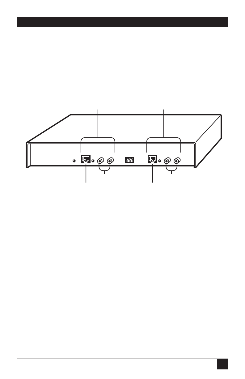
3.1 Front Panel
The Fiber Optic Converter I has one
female RJ-45 copper connector on
the front panel. The Fiber Optic
Converter II has two RJ-45
connectors on the front panel.
Figure 3-1 shows the front panel
of the Fiber Optic Converter II.
You can configure the RJ-45
3. Hardware
Figure 3-1. Front Panel of the Fiber Optic Converter II.
connectors in several ways by using
the Config switch on the Converter’s
front panel. The RJ-45 connectors
can be configured to connect to
either the Ring In or Ring Out
port of a MAU. You can also
configure them for lobe extension
applications.
Configuration of the RJ-45
connectors is covered in Chapter 4.
The connectors labeled RX (for
receive) and TX (for transmit) are
ST receptacles for connection to
fiberoptic cables. The Fiber Optic
Converter I has two fiberoptic
connectors. The Fiber Optic
Converter II has four. SMA fiberoptic connectors are an option on
all models.
The power cord receptacle and fuse
are located on the back panel.
Channel 1 Channel 2
POWER DATA
RJ45 Copper Connector
RX TX
Fiber Connectors
RX TXCONFIG
DATA
Fiber Connectors
RJ45 Copper Connector
Page 13

14
FIBER OPTIC CONVERTERS I & II
3.2 LEDs
Figure 3-2 shows the front-panel
LEDs.
Figure 3-2. Front Panel LEDs.
When the Power LED is lit, power is
being supplied to the unit. When the
Data LED is lit, data is being
transmitted on the RJ-45 side.
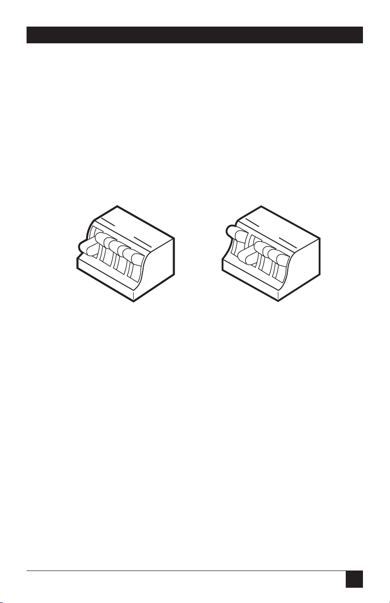
3.3 RJ-45 Connectors
Figure 3-3 shows the transmit and
receive pins of the RJ-45 connectors
in all configurations. Configuration
of the RJ-45 copper connectors is
discussed in Chapter 4.
RJ-11 male connectors may be used
instead of RJ-45 male connectors on
the twisted-pair cable connected to
the RJ-45 connector. Whether you
use RJ-45 or RJ-11 male connectors,
the transmit and receive pins are
always the four center pins in the
connector, as shown in Figure 3-3.
NOTE
The shielded or unshielded
twisted-pair copper cable
used with the Converters
must have at least two
twisted pairs of wire. This
means a minimum of four
separate wires, whether or
not all four will be used.
Also, the cable must be
wired “straight through,” as
shown in Figure 3-4. Do not
twist transmit and receive
wires in the same twisted
pair; Figure 3-4 shows how
to avoid this.
POWER DATA
RX TX
RX TXCONFIG
DATA
Page 14

15
CHAPTER 3: Hardware
Figure 3-3. RJ-45 Copper Connector Transmit and Receive Pins.
RJ-45 Connector
Pin Function
Configuration A Pins B Pins
Ring In Transmit Receive
Ring Out Receive Transmit
Lobe Extension Receive Transmit
Station End
Lobe Extension Transmit Receive
MAU End
Figure 3-4. Straight-through Wiring.
A pins
RJ45 connector
B pins
A, B, C, and D represent the four center pins of an RJ45 or RJ11 connector.
A
B
C
D
A & D in the same pair
D
A
C
B
B & C in the same pair
D
C
B
A
Page 15

16
FIBER OPTIC CONVERTERS I & II
3.4 Config Switch
The Config switch on a Converter’s
front panel is used to configure the
RJ-45 copper connectors for the
different applications mentioned
in the previous section, RJ-45
Connectors. Figure 3-5 shows the
functions of different positions of
the switch.
Phantom refers to the phantom
voltage that is required from the
Converter when it is connected
directly to a station port on a MAU,
such as in a lobe extension
application. When the switch is on
the On position, phantom voltage
is presented.
The Station switch is used in lobeextension applications when the
converter is on the station end of the
lobe. When the Station switch is in
the On position, phantom voltage
from the station is detected by the
converter.
NOTE
The converter will not
operate if Switch 3
(Phantom) and Switch 4
(Station) are in the On
position at the same time.
Specific instructions for setting the
Config Switch are given in Chapter 4.
Figure 3-5. Config Switch Functions.
(Phantom)
(Station)
Ring In
Ring Out
1 2 3 4
OPEN
Off
Channel 1
Channel 2
On
Channel 3
Channel 4
Page 16

17
CHAPTER 4: Installation
In this chapter, installation
procedures are given for the
following:
• Main ring installation
• Lobe extension installation
4.1 Network Planning
A floor plan of the area in which
your network will operate is vital for
planning. You should also draw a
detailed map of the installation. You
should know where you want all
MAUs, stations, Fiber Optic
Converters, and bridges to be
located, and what wire gauge or
cable type the main ring and station
lobes will use.
Plan the network to have the
smallest possible number of wiring
closets. This allows for greater lobe
lengths and can facilitate network
expansion at a later date.
The maximum number of attaching
devices on a single ring using Type 3
cable is 72. The maximum number
of attaching devices on a ring using
Type I or Type 2 cable is 260.
Source-routing token-ring bridges
may be used to more efficiently
partition the network. They connect
rings and allow greater control over
network traffic.
4.1.1 F
IBEROPTICSECTIONS
As long as the fiberoptic sections of
the network do not exceed maximum
distances, their lengths can be
disregarded when you calculate
main ring and station lobe lengths.
There may be as many as four pairs
of optical fiber connectors between
Converters, including the connectors
used to attach to the Converters.
With the Fiber Optic Converter II,
which has two channels, each
channel may have up to four pairs
of optical fiber connectors.
4. Installation
Figure 4-1. Max. Number of Fiber Connectors Between Converters.
LT221A LT221A
RX
TX
Optical cables and Connectors
1st
pair
2nd
pair
3rd
pair
4th
pair
TX
RX
Page 17

18
FIBER OPTIC CONVERTERS I & II
4.1.2 C
OPPERSECTIONS
Copper sections of the ring are
planned in the usual way, taking into
account the main ring length, lobe
lengths, number and type of MAUs,
copper cable type, and other factors.
4.1.3 C
ONVERTERPLACEMENT
The Fiber Optic Converter may be
either rack-mounted or placed on
a shelf or table. An optional rackmount kit (model RM-S00) is
available which allows installation
in a standard 19” equipment rack.
4.2 Installation in the Main Ring
Once the network has been fully
planned, all devices have been
placed and the proper cabling has
been routed to all areas where it will
be needed, use the following
procedure to finish the installation.
(If you are using Converters to
extend an individual lobe, don’t
use this section. See Chapter 4.)
1.Configure each Converter’s
RJ-45 connectors for their
intended use with the Config
Switch, located on a convertor’s
front panel. A Fiber Optic
Converter II has two RJ-45
connectors; a Fiber Optic
Converter I has one. Figure 4-2
shows a sample application and
tells how the RJ-45 connectors
must be configured.
Figure 4-2. Configuration Example.
Ring In Ring Out
Configure channel 1
as ring out
POWER DATA
RX TX CONFIG
Configure channel 2
as ring in
RX TX
DATA
LT221A
MAU
Page 18
19
CHAPTER 4: Installation
NOTE
a) Because the Fiber Optic
Converter I has only one
RJ-45 connector (it uses
only Channel 1), the setting
of Switch 2 can be
disregarded.
b) When converters are used
in the main ring, Switches 3
and 4 should always be in
the up position (open).
Refer to Figure 4-3 for switch setting
information. Configure the RJ-45
connector as Ring In if it connects
to Ring Out of a MAU, and vice
versa. See Figure 4-2 for an example.
(More information on the Config
switch is given in Chapter 3.)
Channel 1 - Ring Out
Channel 2 - Ring In
Channel 1 - Ring In
Channel 2 - Ring Out
OPEN
1 2 3 4
Switch 1 - down
Switch 2 - up
Switch 3 - up
Switch 4 - up
OPEN
1 2 3 4
Switch 1 - up
Switch 2 - down
Switch 3 - up
Switch 4 - up
Figure 4-3. Config Switch Settings for Main Ring Installations.
2.Plug the power cords into the
backs of all Converters and into
electrical outlets.
3.Connect the fiberoptic cables to
the appropriate connectors on
the Converters. TX on a
converter must connect to RX
on its mate. Two optical fibers
are required between each pair
of the Fiber Optic Converter I;
four optical fibers are required
between each pair of the Fiber
Optic Converter II.
4.If the network is not activated,
connect the RJ-45 pins on the
converters to the appropriate
Ring In and Ring Out
connectors on the MAUs. (Ring
In receives the cable from the
previous MAU or Converter;
Ring Out connects to the cable
going to the next MAU or
converter.)
Bring up the network and make
sure it is operating properly.
Page 19

20
FIBER OPTIC CONVERTERS I & II
If the network is already
operating, the Converters may
be installed in the main ring by
connecting the RJ-45 ports on
the Converters to the
appropriate Ring In and Ring
Out connectors on the MAUs, as
long as the ring is not broken for
more than five to ten seconds.
CAUTION
If the main ring is broken for
more than five to ten
seconds, the network will be
completely disabled and will
have to be restarted. Data
loss may occur.
5. The installation is complete. See
Chapter 3 for a description of
LED operation.
4.3 Installation Between a MAU
and a Station
The Fiber Optic Converters can be
used to extend individual station
lobes.
The network should be fully planned
before installation of converters.
Refer to Section 4.1.
The Converters may be either rackmounted or placed on a she!f or
table.
Follow these steps to install the Fiber
Optic Converter between a MAU
and a station.
1. Decide which lobes require
converters.
2. Refer to Figure 4-4 to determine
the maximum copper and
fiberoptic cable lengths.
Figure 4-4. Maximum Cable Lengths.
MAU
A
LT221A LT221A
3300 feet
maximum
B
CopperCopper Optical
PC
Page 20

21
CHAPTER 4: Installation
3. Connect optical cable to the
transmit and receive connectors
on the Converters. TX on a
Converter must connect to RX
on its mate.
There may be as many as four
pairs of optical fiber connectors
between Converters, including
the connectors used to attach
the cable to the Converters. With
the Fiber Optic Converter II,
which has two channels, each
channel may have up to four
pairs of connectors.
Figure 4-5. Connecting the Cable to the Converters.
4.Configure each Converter using
the Config switch on its front
panel. The Converter that is
closest to the MAU requires a
different switch setting than the
Converter closest to the station.
Use the Figure 4-6. (More
information on the Config
switch is given in Chapter 3.)
Converter
nearest station
Converter
nearest MAU
Switch 1 - up
Switch 2 - up
Switch 3 - down
Switch 4 - up
OPEN
1 2 3 4
Switch 1 - down
Switch 2 - down
Switch 3 - up
Switch 4 - down
OPEN
1 2 3 4
Figure 4-6. Config Switch Settings for Lobe Extensions.
LT222A LT222A
RX
TX
Optical cables and Connectors
1st
pair
2nd
pair
TX
3rd
pair
4th
pair
RX
Page 21

22
FIBER OPTIC CONVERTERS I & II
NOTE
Because Switches 3 and 4
control both channels of the
Fiber Optic Converter II, both
channels must be used for
the same purpose. For
example, if Channel 1
connects to a station, then
Channel 2, if used, must also
connect to the station.
5. Turn off the stations to which
the lobes will attach, and
connect the copper cable
between the stations and the
Converter. Connect the copper
cable between the MAU and its
closest Converter.
6. Attach the power cords to the
Converters and plug them into
a power source.
7. Turn on the station or stations.
8. The installation is complete. See
Chapter 3 for a description of
LED operation.
Page 22

1000 Park Drive • Lawrence, PA 15055-1018 • 724-746-5500 • Fax 724-746-0746
© Copyright 2002. Black Box Corporation. All rights reserved.
 Loading...