

Page 1

LRU4240
Dual Trunk E1 Router
User Guide
Software revision 2.3RT
Part 098-04240-18 Rev. 12
October 2003
TECHNICAL: 0118 96 56 000
SALES: 0870 90 10 750
FAX: 0118 96 55 001
ADDRESS: 464 Basingstoke Road, Reading, Berkshire RG2 0BG
WEB: www.blackbox.co.uk
Page 2

Dual Trunk E1 Router
How to Contact Your Local Black Box
Austria: Sweden:
Black Box gmbh Black Box AB
Tel: 01 256 98 56 Tel: +46 8 44 55 870
Fax: 01 256 98 50-100 Fax: +46 8 38 04 30
Web Site: www.black-box.at Web Site: www.Blackbox.ab.se
France: Italy:
Black Box Catalogue Black Box Italia s.p.a.
Tel: 01 45 60 67 00 Tel: 02 27404 280
Fax: 01 45 60 67 47 Fax: 02 27400 219
Web Site: www.blackbox.fr Web Site: www.blackbox.it
Deutschland: Denmark:
Black Box Deutschland Black Box Denmark
Tel: 0811/5541-0 Tel: +45 5663 3010
Fax: 0811/5541-499 Fax: +45 5665 0805
Web Site: Web Site:
www.blackbox-deutschland.com Web Site: Web Site: www.blackbox.dk
Switzerland: Spain:
Black Box (Schweiz) AG Black Box Comunicaciones S.A.
Tel: 055 451 70 70 Tel: 91 659 0191
Fax: 055 451 70 75 Fax: 91 623 9784
Web Site: www.black-box.ch Web Site: www.blackbox.es
Netherlands: Belgium:
Black Box Datacom BV Black Box Communications S.A. N.V.
Tel: 03032417700 Tel: 02 725 85 50
Fax: 0302414746 Fax: 02 725 92 12
Web Site: www.blackbox.nl Web Site: www.blackbox.be
Norway: Finland:
Black Box Norge as. Black Box Finland Oy.
Tel: +47 55 300 700 Tel: +358 (0) 201 888 888
Fax: +47 55 300 701 Fax: +358 (0) 201 888 808
Web Site: www.blackboxnorge.no Web Site: www.blackbox.fi
U.S.A. : Chile:
Black Box Corporation Black Box Chile
Tel: 724-746-5500 Tel: 00 562 6680 141
Fax: 724-746-0746 Fax: 00 562 6680 140
Web Site: www.blackbox.com Web Site: www.Blackbox.cl
Brazil: Australia:
Black Box Do Brasil. Black Box Network Services Australia P/L
Tel: (011) 5515-4000 Tel: 03-9879-7100
Fax: (011) 5515-4002 Fax: 03-9870-2955
Web Site: www.blackbox.com.br Web Site: www.blackboxoz.com.au
ii SALES: 0870 90 10 750 Dual Trunk E1 Router User’s Guide
Page 3

Copyright
ISO Compliance
Warning
Caution
Dual Trunk E1 Router
Copyright © 1998, BLACK BOX Ltd
World copyright reserved. No part of this publication may be stored in a retrieval system,
transmitted, or reproduced in any way, including but not limited to photocopy, photograph,
magnetic, chemical, or other record, without the prior agreement and written permission of
BLACK BOX Ltd.
Products Manufactured Under
An ISO 9001 Certified
Quality Management System
The Dual Trunk E1 Router complies with FCC Part 15 of the Federal Communications
Commission (FCC) Rules concerning radio frequency emissions for Class A computing
devices. The following section is required by the FCC.
In accordance with FCC Part 15 section 15.21, changes or modifications made by the buyer that
are not expressly approved by BLACK BOX Ltd could void the buyer’s authority to operate
this equipment.
This equipment has been tested and found to comply with the limits for a Class A digital
device, pursuant to Part 15 of the FCC Rules. These limits are designed to provide reasonable
protection against harmful interference when the equipment is operated in a commercial
environment. This equipment generates, uses, and can radiate radio frequency energy and, if not
installed and used in accordance with the instruction manual, may cause harmful interference to
radio communications. Operation of this equipment in a residential area is likely to cause
harmful interference in which case the user will be required to correct the interference at his
own expense.
This Class A digital device meets all requirementsof the Canadian Interference-Causing
Equipment Regulations.
Cet Appareil numerique de la classe A respecte toutes les exigences du Reglement sur le
materiel brouilleur du Canada.
Dual Trunk E1 Router User’s Guide TECHNICAL: 0118 96 56 000 iii
Page 4

Dual Trunk E1 Router
NOTE: As per the Voluntary Control Council for Interference by Information Technology
Equipment (VCCI), the Dual Trunk E1 Router complies with VCCI Class 1 ITE. This
equipment is in the 1st Class category (information equipment to be used in commercial and/or
industrial areas) and conforms to the standards set by the Voluntary Control Council for
Interference by Information Technology Equipment aimed at preventing radio interference in
commercial and/or industrial areas. Consequently, when used in a residential area or in an
adjacent area thereto, radio interference may be caused to radios and TV receivers, etc. Read
the instructions for correct handling.
Regulatory Information
The equipment complies with the following applicable European Directives 73/23/EEC,
89/336/EEC, 92/31/EEC, 93/68/EEC and 1995/5-EC.
Customer Information
The equipment complies with Part 68 of the FCC Rules. You will find the label located on the
bottom of the enclosure. This label contains the FCC Registration Number and Ringer
Equivalence Number (REN) for this equipment. You must, upon request, provide this
information to your telephone company.
Incidence of harm: If your telephone equipment causes harm to the telephone network, the
telephone company may discontinue your service temporarily. If possible, they will notify you
in advance. But if advance notice is not practical, you will be notified as soon as possible. You
will be informed of your right to file a complaint with the FCC.
Rights of the telephone company: Your telephone company may make changes in its facilities,
equipment, operations or procedures that could affect the proper functioning of your equipment.
If they do, you will be notified in advance to give you an opportunity to maintain uninterrupted
telephone service.
Malfunction of the equipment: In the event this equipment should fail to operate properly,
disconnect the unit from the telephone line. Try using another FCC approved telephone in the
same telephone jack. If the trouble does not persist and appears to be with this unit, disconnect
the unit from the telephone line and discontinue use of the unit until it is repaired. Please note
that the telephone company may ask that you disconnect this equipment from the telephone
network until the problem has been corrected or until you’re sure that the equipment is not
malfunctioning.
iv SALES: 0870 90 10 750 Dual Trunk E1 Router User’s Guide
Page 5

Dual Trunk E1 Router
Preface 9
Audience 9
Organization 9
Conventions 10
Symbols 10
Typography 11
Black Box Technical Support 11
Returning a Unit 12
Send Us Your Comments 12
Chapter 1, Product Overview 13
Product Overview 13
Applications 14
Dual independent links application 14
Load balancing 14
Redundancy 14
Multilink application 15
Redundancy 15
Monitoring the Entire WAN Protocol Stack 16
Monitoring Higher Protocol Layers 16
Chapter 2, Installation 17
Unpacking and Checking Equipment 17
Package Contents 17
Before You Install 17
Site Requirements 17
Installation 18
Installing the Dual Trunk E1 Router 18
Installation Using AC Power 18
Installation Using DC Power 19
Chapter 3, Terminal Setup 21
Navigating The Front Panel 21
Front Panel Display 23
Dual Trunk E1 Router User’s Guide
Default Display 23
The EFS Field 23
TECHNICAL: 0118 96 56 000 1
Page 6

Dual Trunk E1 Router
The Configuration Options 23
The Test Options 24
To Stop a Test 25
The Monitor Options 25
Terminal User Interface Mode 25
Terminal Interface Navigation 26
Setting a Menu Parameter 26
Attaching to a Terminal 26
Using the Ethernet port as management interface 27
Using Terminal Software 27
Terminal Setup 27
Hyperterm Windows Setup 27
Logging On from a Terminal 30
Logging Off from a Terminal 31
Adjusting COMM Port Settings 31
Logging on from a Telnet Connection 31
Configuring Access Rights 32
Assigning User Passwords 32
Chapter 4, Access Configuration 33
Overview of Access Configuration 33
Configuring LAN Interface 35
Setting ID, Date, Time, and Network Timing 35
Unit Configuration− Menu 4A 35
Net Configuration and Status 37
Configuring Timeslot Allocations 37
Configuring WAN Protocol 38
Configuring Single Link PPP Interface 38
Configuring independent PPP links Interfaces 39
Configuring MLPPP Interface 39
Configuring PPP Protocol Parameters 39
Configuring single link Frame Relay 40
Configuring independent Frame Relay links 40
Configuring Multilink Frame Relay 40
Configuring Frame Relay DLCIs 40
Dynamic configuration (LMI) 40
Dual Trunk E1 Router User’s Guide
Manual DLCI configuration 41
TECHNICAL: 0118 96 56 000 2
Page 7

Dual Trunk E1 Router
Mapping DLCIs to IP Addresses 41
Configuring SLIP 41
Configuring TUI Access Rights 42
Configuring Radius Authentication 42
Enabling/Disabling Traffic Monitoring 44
Configuring SNMP. 44
Configuring Time and Date Synchronization 45
Configuring DHCP 46
Chapter 5, Bridging Configuration 47
Overview of the Configuration 47
Bridging Configuration 47
Managing the unit in Bridging mode 48
VLAN Forwarding support 48
Management VLAN ID 48
Bridging Application Examples 48
WAN Gateway for IP VPN Application 48
Point-to-point LAN Extension 48
Multipoint Bridge example 48
Configuring Bridging 50
Configuring static MAC Bridge Routes 50
Displaying MAC to Port Map Table 51
Configuring the Firewall 52
52
Chapter 6, Routing Configuration 53
Overview of the Configuration 53
Configuring Routing Mode 54
Configuring Default Gateway 54
Configuring Static Routes 55
Load balancing over independent links 57
Configuring Dynamic Routing 57
Configuring NAT 57
NAT Configuration menus 58
Configuring NAT for single link ISP 59
Configuring NAT for Multihoming 60
Configuring NAT for Internet access and Frame Relay network 61
Dual Trunk E1 Router User’s Guide
Single link Internet Example 60
TECHNICAL: 0118 96 56 000 3
Page 8

Dual Trunk E1 Router
Chapter 7, Firewall Configuration 63
Configuring the Firewall 63
64
Chapter 8, Diagnostics 65
Required Tools and Equipment 65
Performing Tests from the Front Panel 65
Self Test 65
Loopback Tests 66
Loop NET Test 66
Loop Payload Test 67
Loop Up Remote and Loop Down Remote Tests 67
Pattern Tests 68
QRW Pattern Test 68
Other Pattern Tests 68
Lamp Test 69
Performing Diagnostics from the Terminal 70
Menu-9 Diagnostics 70
Menu-9A Physical Layer Diagnostics 70
Performing a Test from Menu-9A Physical Layer Diagnostics 70
Performing Diagnostics From Telnet 70
Link Layer Diagnostics and Delay Monitoring 71
Link-based Testing for Public Packet Networks 72
Delay Monitoring for TCP/IP 72
Non-Disruptive Testing 72
Menu-9B—Link Layer Diagnostics 72
Chapter 9, Monitoring and Management 75
Monitoring and Management 75
Terminal User Interface Access Methods 76
Monitoring Performance 76
Displaying Performance Reports 76
Routing Monitoring 79
Dual Trunk E1 Router User’s Guide
Performance Report Menus 76
Performance Data Report Events 78
Event Log 78
TECHNICAL: 0118 96 56 000 4
Page 9

Dual Trunk E1 Router
Delay Monitoring 79
Monitoring Status 80
Menu-1 Main Status 80
Main Status Fields 80
Clearing Error Counters 80
Menu-2 Data Status 80
In–band Management 80
In-band Network Registers, 24 Hour Detail 81
RMON-2 81
Protocol Directory 81
Protocol Distribution 82
Network Layer and Application Layer Host Tables 82
Network Layer and Application LayerMatrix Tables 83
Chapter 10, Alarms 85
Configuring Alarm Conditions 85
How Alarm Reports Are Displayed 85
Menu-8 Alarm 86
Menu-8A Alarm Configuration 86
Menu-8C Miscellaneous Management Configuration 86
Menu-8E Modem Initialization Strings 86
Chapter 11, Troubleshooting 87
Troubleshooting the Unit 87
Unit Problems 87
Network Problems 90
Appendix A, Specifications 95
Technical Specifications 95
Performance 95
LRU4240 Network Interface 95
LRU4240 Data Interface 95
Power Options 96
Physical 96
Environmental 96
Reliability 96
LRU4240 Diagnostics 96
Dual Trunk E1 Router User’s Guide
TECHNICAL: 0118 96 56 000 5
Page 10

Dual Trunk E1 Router
Dual Trunk E1 Router 98
99
Appendix B, Cable and Connector Pin Assignments 101
E1 Network Pin Assignments 101
Communication Port Pin Assignments 102
DE-9 to DB-25 Adapter Pin Assignments 102
102
Appendix C, Software Upgrade 103
Software Download 103
Using the Download Menu Utility 103
Setting Up for TFTP 103
Abnormal Termination 104
Error Indicators 104
Download Aborted by User 105
Programming software upgrades remotely 106
Software-Only Upgrades 107
Changing software 107
107
Appendix D, Menus 109
Appendix E, Router Command Line Interface Reference 137
Access To Router Command Line 137
Configuring the router automatically 137
Router Command Line Help 138
CLI Command Modes 140
Unit Command Reference 141
configure terminal 142
quit 142
show running-config 142
show unit id 142
e1 framing 143
e1 line-impedance 143
e1 timeslot 143
interface IFNAME icmp-redirect 143
interface IFNAME ip-addr 143
Dual Trunk E1 Router User’s Guide
TECHNICAL: 0118 96 56 000 6
Page 11

Dual Trunk E1 Router
interface enet 144
interface frame-relay dlci 144
interface frame-relay lmi 144
interface frame-relay map 145
interface frame-relay map clear 145
ip bridge static-route 145
ip dhcp-relay 145
ip firewall 145
ip nat 146
ip nat global 146
ip nat local-addr 146
ip nat static 146
ip route 146
ip route bridge-route-aging-time 147
ip route default-gateway 147
ip route load-balancing 147
ip route mode 147
ip route vlan-id 148
ip route vlan-priority 148
ip static-route clear 148
multilink 148
multilink mfr 148
multilink mlppp 148
t1 framing 148
t1 lbo 149
t1 timeslot 149
time-sync 149
time-zone 149
traffic monitoring 149
traffic type 150
unit alarm 150
unit ansi-fdl 150
unit clock 150
unit comm-port 150
unit id 150
unit idle-code 150
unit management 150
Dual Trunk E1 Router User’s Guide
TECHNICAL: 0118 96 56 000 7
Page 12

Dual Trunk E1 Router
unit modem 151
unit outage 151
unit protect-mode 151
unit radius 151
unit remote-comm 151
unit sla 151
unit snmp 151
unit yellow-alarm 151
wan-port in-service 151
Kernel Command Reference 152
interface IFNAME 152
quit 152
debug zebos events 152
debug zebos kernel 153
debug zebos packet 153
show debugging zebos 153
show interface IFNAME 153
show ip route 153
show running-config 154
RIP Command Reference 155
configure terminal 155
router rip 155
interface IFNAME 155
quit 155
debug rip 155
distance 156
ip rip receive-packet 156
ip rip receive version 156
ip rip send-packet 156
ip rip send version 157
ip rip send version 1-compatible 157
ip split-horizon 157
neighbor 158
network 158
passive-interface 158
route 158
router rip 159
Dual Trunk E1 Router User’s Guide
TECHNICAL: 0118 96 56 000 8
Page 13

Dual Trunk E1 Router
show debugging rip 159
show ip protocols 159
show running-config 160
show ip rip 160
timers 160
version 161
OSPF Command Reference 161
area authentication 161
area default-cost 162
area export-list 162
area import-list 162
area range 163
area shortcut 163
area stub 164
area virtual-link 164
auto-cost 165
compatible rfc1583 166
debug ospf event 166
debug ospf ism 166
debug ospf lsa 167
debug ospf nsm 167
debug ospf packet 168
debug ospf route 168
debug ospf zebos 168
default-information originate 169
default-metric 169
description 170
distance 170
distribute-list 170
ip ospf authentication 171
ip ospf authentication-key 171
ip ospf cost 172
ip ospf database-filter 172
ip ospf dead-interval 173
ip ospf hello-interval 173
ip ospf network 174
ip ospf priority 174
Dual Trunk E1 Router User’s Guide
TECHNICAL: 0118 96 56 000 9
Page 14

Dual Trunk E1 Router
ip ospf retransmit-interval 175
ip ospf transmit-delay 175
login 176
match interface 176
match metric 177
match route-type external 177
match tag 177
neighbor 178
network area 178
opaque 179
opaque-lsa-capable 179
ospf abr-type 180
ospf authentication-key 180
ospf cost 180
ospf dead-interval 181
ospf hello-interval 181
ospf network 182
ospf priority 182
ospf router-id 183
ospf transmit-delay 183
passive-interface 183
redistribute 184
refresh timer 184
router-id 185
router ospf 185
set metric-type 185
set next-hop 186
set tag 186
show debugging ospf 187
show ip ospf 187
show ip ospf border-routers 188
show ip ospf database 189
show ip ospf database asbr-summary 190
show ip ospf database external 190
show ip ospf database network 191
show ip ospf database opaque-area 192
show ip ospf database opaque-link 193
Dual Trunk E1 Router User’s Guide
TECHNICAL: 0118 96 56 000 10
Page 15

Dual Trunk E1 Router
show ip ospf database router 193
show ip ospf database summary 194
show ip ospf interface 195
show ip ospf neighbor 196
show ip ospf route 197
show ip protocols 198
show memory all 198
show memory lib 200
show memory ospf 201
summary-address 202
timers spf 202
Index 203
Dual Trunk E1 Router User’s Guide
TECHNICAL: 0118 96 56 000 11
Page 16

Dual Trunk E1 Router
Dual Trunk E1 Router User’s Guide
TECHNICAL: 0118 96 56 000 12
Page 17

Dual Trunk E1 Router
Dual Trunk E1 Router User’s Guide
TECHNICAL: 0118 96 56 000 13
Page 18

Dual Trunk E1 Router
Dual Trunk E1 Router User’s Guide
TECHNICAL: 0118 96 56 000 14
Page 19

Dual Trunk E1 Router
Dual Trunk E1 Router User’s Guide
TECHNICAL: 0118 96 56 000 15
Page 20

E1 NTU with QoS User’s Guide
16 SALES:0870 90 10 750 Dual Trunk E1 Router User’s Guide
Page 21

AUDIENCE
This Dual Trunk E1 Router User’s Guide is intended for network professionals who want
instructions for installing and configuring their digital service unit router.
ORGANIZATION
Chapter 1, “Product Overview,” provides a description of the features of the Dual Trunk
E1 Router, and its placement in a Wide Area Network.
Chapter 2, “Installation,” provides a description of the LRU4240, the components you
should have received in your shipping carton, and the hardware requirements for setting up
the LRU4240 in your network.
Chapter 3, “Terminal Setup,” provides instructions on connecting your device to a
terminal, logging on to the device; explains how to navigate the terminal screens and
configure your device to work with your network.
Chapter 4, “Access Configuration,” contains information about configuring the LAN and
WAN interfaces, the interface IP addresses, NMS IP addresses, Radius authentication,
DHCP, and miscellanous management settings.
Dula Trunk E1 Router
Preface
Chapter 5, “Bridging Configuration,” contains configuration procedures for bridging and
VLAN Bridging applications
Chapter 6, “Routing Configuration,” contains configuration procedures for static and
dynamic routing, and Network Address Translation (NAT)
Chapter 7, “Firewall Configuration,” contains configuration procedures for the firewall
access list
Chapter 8, “Diagnostics,” describes the E1 and in-band tests that can be used to verify the
operation of the device and its associated cabling and equipment.
Chapter 9, “Monitoring and Management,” describes how to monitor and manage the
LRU4240 router. Provides instructions on the option of collecting RMON-2 data.
Chapter 10, “Alarms,” describes alarm conditions and alarm configuration parameters.
Chapter 11, “Troubleshooting,” provides solutions to specific problems.
Appendix A, “Specifications,” provides regulatory compliance information, as well as the
electrical, physical, and networking characteristics.
Appendix B, “Cables and Connector Pin Assignments,” details connector and pin
assignments.
Appendix C, “Software Upgrade” software upgrades and download procedures.
Appendix D, “Menus,” details software menus command and parameters.
Dual Trunk E1 Router User’s Guide TECHNICAL: 0118 96 56 000 9
Page 22

Dual Trunk E1 Router
Appendix E, “Router Command Line Interface Reference” details the router command line
interface commands and parameters
CONVENTIONS
This section describes the conventions used to delineate specific types of information
throughout Black Box user guides.
Symbols
Symbols denote text that requires special attention. The information contained alongside a
symbol corresponds to one of four levels of severity:
NOTE: Follow guidelines in this, or the previous, paragraph to use the Black
Box product more effectively.
CAUTION: Follow guidelines in this, or the previous, paragraph to avoid
equipment damage or faulty application.
WARNING: Follow the instructions in this, or the previous, paragraph to
avoid personal injury.
ELECTRO-STATIC DISCHARGE — CAUTION: Follow the instructions in this,
or the previous, paragraph to avoid the discharge of static electricity, and
subsequent damage to the equipment.
10 SALES: 0870 90 10 750 Dual Trunk E1 Router User’s Guide
Page 23

Typography
Typeface or
Symbol
Dual Trunk E1 Router
This manual delineates the names of files, commands, and actions by using the fonts and
typefaces described in the following table:
Purpose Example
Courier
Font
AaBbCc123
Courier
Font, Bold
AaBbCc123
Palatino Font,
Italic
AaBbCc123
▼
Zapf Dingbats
Font
Palatino Font,
Bold Blue,
Underscore
AaBbCc123
Palatino Font,
Blue
AaBbCc123
or
AaBbCc123
Helvetica Bold Denotes actual markings on front or back
The names of commands, files, and
directories, as well as on-screen
computer output.
The input you provide, as contrasted with
on-screen computer output.
Keystrokes that you must provide to use
the application.
Command-line placeholder that you
replace with a real name or value.
Book titles, new words or terms, or
words that need to be emphasized.
Symbol that denotes a single-step
procedure or task. Procedures requiring
more than one task are numbered.
Hyperlinks in the table of contents.When
viewing the Portable Document Format
(PDF) version of the user guide, you can
click on one of these to jump directly to
the selected subject matter.
Hyperlinks throughout general text.
panels.
Edit your.login file.
Use ls -a to list all files.
machine_name% You have
mail.
machine_name% su
Press Ctrl-L to refresh the screen.
To delete a file, type rm filename
Refer to Chapter 6 in the User Guide.
These are called class options.
Yo u must be logged in as root to access
this directory.
Attach the cable to the TERMINAL port
BLACK BOX TECHNICAL SUPPORT
If you should experience difficulty with the setup and/or operation of your Black Box
equipment, the Black Box Technical Support staff can assist you at any time.
Telephone 0118 96 56 000
FAX 0118 96 55 001
Dual Trunk E1 Router User’s Guide TECHNICAL: 0118 96 56 000 11
Page 24

Dual Trunk E1 Router
Internet www.blackbox.co.uk
RETURNING A UNIT
Use the following procedure if you need to return a unit for service or repair,
1. Contact the Black Box Customer Service Department at
0870 90 10 750, or fax a request to 0118 96 55 001 to obtain an ERN
(Equipment Returns Number) number.
2. Package the unit carefully and, before sealing the shipping carton, include any
information you can provide about the problems you are currently experiencing
with the unit.
3. Attach an address label to the shipping carton. Be sure to include the ERN
number:
Customer Service Department
Black Box
464 Basingstoke Road
Reading, Berkshire RG2 0BG
ERN # ___________
SEND US YOUR COMMENTS
Please let us know if this user guide meets your requirements.
Does the manual answer your questions?
Is the manual thorough?
Is the manual easy to use: can you find the information you need?
Is anything missing from the manual?
What would you like to see in the manual?
Black Box
FAX 0118 96 55 001
All suggestions and comments are appreciated.
12 SALES: 0870 90 10 750 Dual Trunk E1 Router User’s Guide
Page 25
PRODUCT OVERVIEW
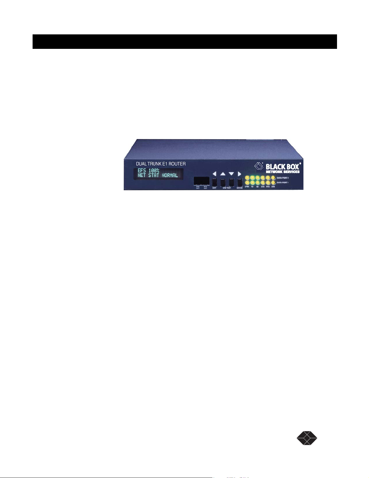
The Dual Trunk E1 Router is an intelligent network access solution providing connectivity to public
and private packet-based networks. Available as a standalone unit it integrates a dual CSU/DSU,
routing, and WAN Probe in one single platform.
Figure 1-1 Dual Trunk E1 Router
Dual Trunk E1 Router
Product Overview 1
The Dual Trunk E1 Router supports bridging, static routing, and dynamic routing RIP1, RIP2, and
OSPF. The two E1 links can be configured as either two independent PPP or Frame Relay links to
different destinations, or a single multilink connection (MLPPP or MLFR FRF.16 ) to one
destination for load balancing and link redundancy application. A firewall permits or denies access
based on source and destination IP addresses.
Configuration and troubleshooting is accessible to novice and advanced users with the availability
of a menu-based Terminal User Interface and an industry-standard Command Line Interface (CLI).
Complete router configuration can be automated remotely by downloading router configuration
files.
The Dual Trunk E1 Router is SNMP-manageable, offers menu-driven configuration, includes
comprehensive diagnostics, in-band management, and network performance monitoring (RMON1
and RMON2). These tools provide visibility on the usage of the WAN connections.
Dual Trunk E1 Router User’s Guide TECHNICAL: 0118 96 56 000 13
Page 26
Dual Trunk E1 Router
APPLICATIONS
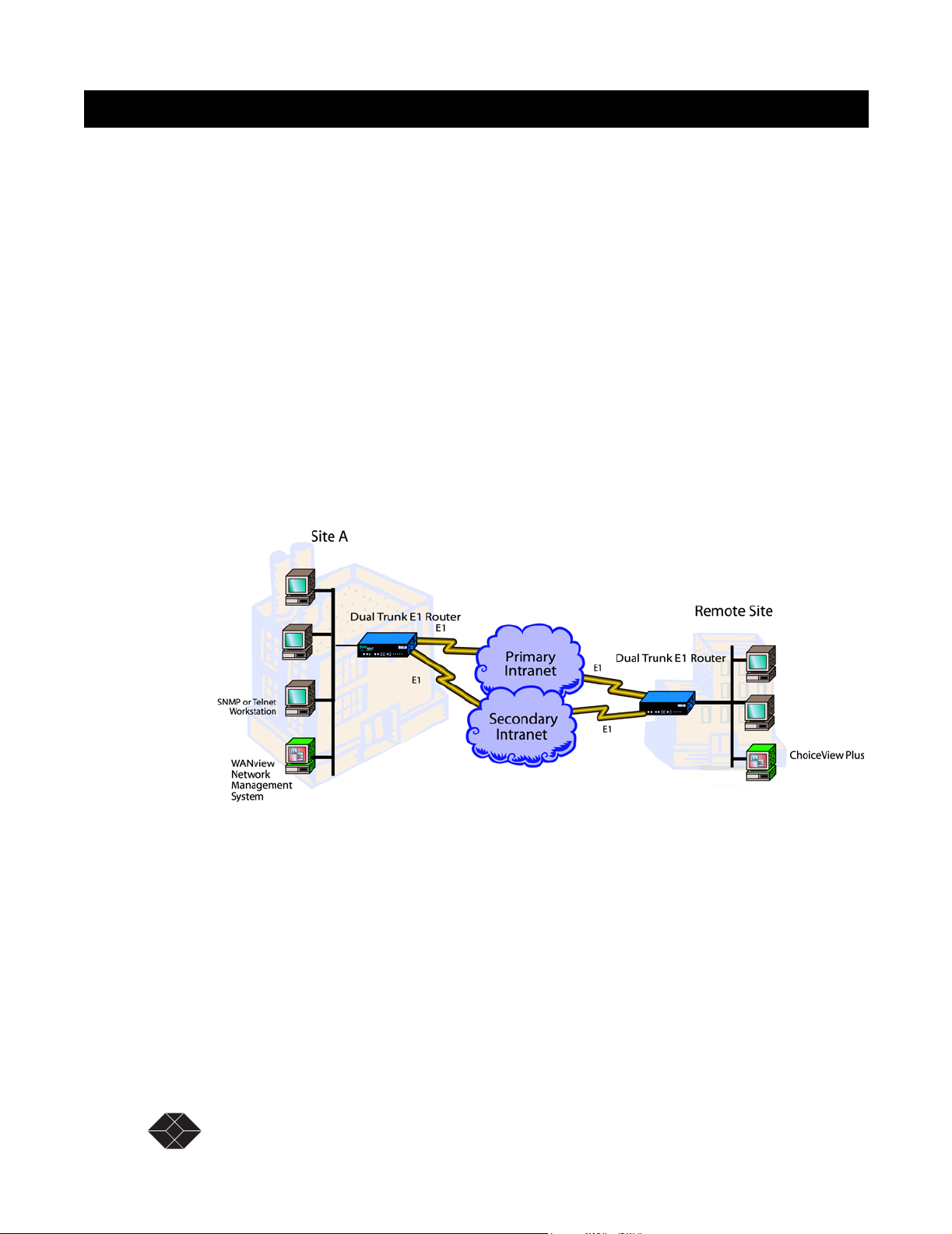
Dual independent links application
Load balancing
When multiple paths exist to the same destination, sending all IP packets on a single route is
probably not the most efficient use of the available bandwidth. Load balancing is the practice of
distributing traffic among multiple paths to the same destination to achieve higher throughput and
avoid delays.
The Dual E1 Trunk Router IP routing engine maintains a cost metric parameter with each route
learnt dynamically or programmed statically. If more than one route of equal cost is found for a
particular destination, the routing engine will distribute the packets equally among the available
routes using a round-robin algorithm.
If multiple routes are found with unequal costs then the route with lesser cost metric is chosen.
Redundancy
With multiple paths to the same destination, the routing engine also performs redundancy at both
the physical layer and the network layer. By monitoring the status of the physical link interface and
the PPP negotiation, the unit knows when a link is physically down or a PPP connection is down.
When either events occurs, the routing engine will balance traffic to the active link.
14 SALES: 0870 90 10 750 Dual Trunk E1 Router User’s Guide
Page 27
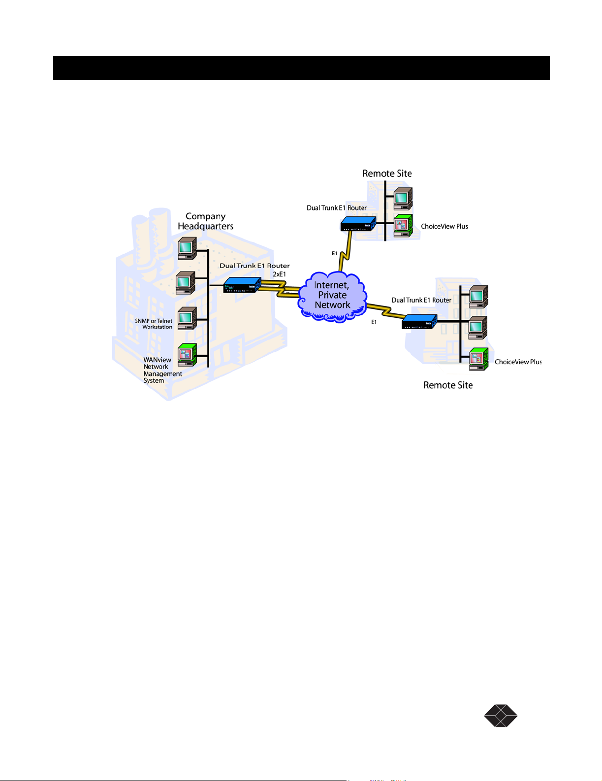
Multilink application
Multilink PPP (MLPPP) or Multilink Frame Relay (MLFR) bundles the two E1 ports to pass traffic
at twice the speed of a single E1 link. The standard MLPPP per RFC1990 facilitates interoperability
with routers from other router vendors.
Dual Trunk E1 Router
A pair of Dual E1 Trunk Router can be deployed in a a back-to-back configuration offering a highspeed 4 Mbps point-to-point LAN extension.
Redundancy
With multilink, redundancy is performed at the link layer, if a link is down the traffic is still carried
over the active link. If a failed link comes back up again it is automatically added to the bundle, and
traffic resumes at twice the speed again.
Dual Trunk E1 Router User’s Guide TECHNICAL: 0118 96 56 000 1-15
Page 28

Dual Trunk E1 Router
MONITORING THE ENTIRE WAN PROTOCOL STACK
With the Dual Trunk E1 Router you can monitor the entire WAN protocol stack. Higher level
protocols can be monitored using RMON-2. PPP connections can be monitored using RMON-1, and
the physical layer can be monitored using diagnostic capabilities as outlined in RFC 1406.
Monitoring Higher Protocol Layers
The Dual Trunk E1 Router includes RMON-2 capabilities. This lets you identify the Top Talkers
(256 greatest bandwidth users), and drill down to the Top Applications to see which applications are
using the most bandwidth. It also lets you track and report traffic sent between pairs of network
addresses and categorizes them by applications and protocols.
Ta b l e 1 - 2 lists the RMON tables supported in RMON-2.
Table 1-1 RMON-2 Tables
RMON-2
Protocol Directory
Network Layer Host
Protocol Distribution
Application Layer Host
Network layer matrix group
Application layer matrix group
Using the optional ChoiceView Plus software application, you can display the statistics gathered by
RMON-2.
Table 1-2 RMON Tables
RMON-1
(Provided with Level 2 & 3)
History Protocol Directory
Events Network Layer Host
Statistics Protocol Distribution
Alarms Application Layer Host
To take advantage of the Dual Trunk E1 Router’s RMON-2 capabilities, Black Box has created an
application, ChoiceView Plus, that allows you to display RMON-2 data in real-time, graphical, and
tabular formats.
16 SALES: 0870 90 10 750 Dual Trunk E1 Router User’s Guide
RMON-2
(Option for Level 2 & 3)
Page 29

Installation 2
UNPACKING AND CHECKING EQUIPMENT
Before you begin the installation, you need to:
• Unpack and inspect the LRU4240 for damage that may have occurred during shipment
• Save all enclosed packing slips, documents, shipping cartons, and packing materials until you
have completed the installation and verified the unit’s operation
Package Contents
Make sure that you have received all the items ordered.
• LRU4240 Dual Trunk E1 Router
• A User Guide
BEFORE YOU INSTALL
Dual Trunk E1 Router
Dual Trunk E1 Router operation requires the proper data port, com port and network cables. If you
don’t have the correct cables, they may be ordered by calling Black Box at (0118) 965-5100 and
asking for Inside Sales, or you may order from the Black Box Online Store on our web site:
www.blackbox.co.uk.
SITE REQUIREMENTS
Install the LRU4240 in accordance with the National Electric Code, ANSI/NFPA 70, Articles 11016, 110-17, and 110-18. This code defines an access area such as a dedicated equipment room or
closet that is clean, well-ventilated, and free of environmental extremes. Allow .5 - 1.0 m (2-3 feet)
of clearance around the unit for access during installation.
The operating environment of the LRU4240 is shown in Tab le .
Table 2-1 Site Environmental Requirements
Item Specification
Operating Temperature 0°C to 50°C (32°F to 122°F) ambient
Storage Temperature -20°C to +60°C (-4°F to 140°F)
Relative Humidity 0% to 95% noncondensing
Maximum Altitude 4.6 km (15,000 ft)
Dual Trunk E1 Router User’s Guide TECHNICAL: 0118 96 56 000 17
Page 30

Dual Trunk E1 Router
Do no
Voltages as high as 200 VDC may exist at the telephone company’s E1 interface in
the form of simplex power. These voltages are hazardous and can cause death or
severe injury! Do not proceed with this installation if any voltage is present between
the send and receive pairs of the network interface. You can ask the serving telephone
company to temporarily disconnect the simplex power during installation.
INSTALLATION
The following procedures outline the steps necessary to install the Dual Trunk E1 Router, power the
device, and attach it to a terminal.
Installing the Dual Trunk E1 Router
The Dual Trunk E1 Router should be installed on a flat, stable surface or mounted on a tray.
To install the Dual Trunk E1 Router on a flat surface:
1. Remove the covering from the four stick-on rubber pads and attach them to the bottom
of the unit.
2. Place the unit on a flat, stable surface.
You may stack other units on top of the Dual Trunk E1 Router.
Installation Using AC Power
To install the Dual Trunk E1 Router using AC power, follow the step below and refer to Figure 2-1:
Insert the power cable into the power receptacle on the Dual Trunk E1 Router rear panel. Connect
the other end to the AC outlet.
The LEDs on the front panel flash and status messages appear on the alphanumeric display as the
Dual Trunk E1 Router runs the Self Test at power up.
NOTE: DC Power may be used as a primary power source or as a backup
power source, should AC power fail.
18 SALES: 0870 90 10 750 Dual Trunk E1 Router User’s Guide
Page 31

Dual Trunk E1 Router
Ground Stud
DC Power Connector
AC Power Connector
Figure 2-1 Back Panel View–Ports and Ground Stud
Installation Using DC Power
You need a tray cable that is UL recognized 14 AWG, 3 conductors, copper strand wire, electrical
power and control cable, type TC: tray cable, 600 V 90°C. Alpha Wire Company No. 45443 is an
example.
To connect the Dual Trunk E1 Router to DC power:
1. Place the unit on a flat surface or tray.
Reserved
(DTE 2)
Reserved
(DTE 1)
AUX BNC
Ethernet Port
COMM Port
Network BNC
Network Port
(AUX)
Network Port
2. Make sure the DC power source is off.
3. Before you connect the unit to the centralized DC power source, strip 2 inches of jacket
material off the tray cable and 1/2 inch of insulation off each wire.
4. Connect the -48 V wire to the positive (+) terminal using a small flat screwdriver to
fasten the wire.
5. Connect the ground wire to the negative (-) terminal using the same method.
The unit is designed to operate with negative voltage; therefore, the positive terminal is
connected to ground.
6. Connect a properly grounded third wire to the ground stud near the terminal block
using a 1/4 inch wrench and fastening torque of 5 inch-pounds.
7. To minimize disturbance to the wires through casual contact, secure the tray cable near
the rack frame using multiple cable ties.
Use at least four cable ties, a minimum of 4 inches apart. The first tie should be within 6
inches of the terminal block.
8. Connect the Dual Trunk E1 Router to a DC power source. Turn on power source.
The LEDs on the front panel flash and status messages appear on the alphanumeric display as the
Dual Trunk E1 Router runs the Self Test at power up.
Dual Trunk E1 Router User’s Guide TECHNICAL: 0118 96 56 000 19
Page 32

Dual Trunk E1 Router
20 SALES: 0870 90 10 750 Dual Trunk E1 Router User’s Guide
Page 33

Terminal Setup 3
The Dual Trunk E1 Router can be operated using basic front panel controls, or through a more indepth terminal interface. It is divided into two main sections listed below:
• Navigating the Front Panel
• Terminal Mode
NAVIGATING THE FRONT PANEL
From the front panel, you can:
• View and change configuration parameters
• Run diagnostic tests
• Monitor the Dual Trunk E1 Router status
The front panel allows access to most of the configuration and monitoring features of the Dual
Trunk E1 Router. You may find that for regular daily use, the front panel provides a quick and easy
means of monitoring the status of your device and changing configuration parameters.
The front panel is controlled using the front panel buttons: EXIT, UP arrow, DOWN arrow, and
ENTER. For an explanation of each button’s function, see Table 3-1.
Dual Trunk E1 Router
Table 3-1 Button Usage
Button Function
Back/Exit Button Cancel an option or exit a menu
Up/Back Button Move backward through the options
Down/Forward Button Move forward through the options
Enter Button Select an option
The front panel and its buttons and LEDs are shown on page page 24. If you wish to disable these
buttons, enable Protect Mode on Menu-4, Main Configuration using the terminal user interface. You
will still be able to view the unit’s settings using the buttons, but you will not be able to change the
settings.
Dual Trunk E1 Router User’s Guide TECHNICAL: 0118 96 56 000 21
Page 34

Dual Trunk E1 Router
3
4 5 6 7 89j kl m 1 2
Figure 3-1 Dual Trunk E1 Router Indications and Buttons
# Description # Description
1 Alphanumeric Display 8 Loopback LEDs
2 Reserved 9 Reserved
3 Reserved j Reserved
4 Back/Exit Button k Reserved
5 Up/Back Button l Reserved
6 Down/Forward Button m Reserved
7 Enter Button
The LEDs for the Ethernet port are located in the back of the unit.
22 SALES: 0870 90 10 750 Dual Trunk E1 Router User’s Guide
Page 35

Dual Trunk E1 Router
Front Panel Display
The front panel alphanumeric display provides a 2-line, 16-character message. It provides access to
the Dual Trunk E1 Router via the front panel buttons. Press the UP ARROW and the DOWN
ARROW keys to move among the various menus. Using the UP ARROW and DOWN ARROW
keys will move you among the categories listed in Table 3-2.
Table 3-2 Front Panel Categories
Field Function
EFS <XXX>% The percentage of time the E1 link has run without error.
CONFIGURATION Access the Dual Trunk E1 Router’s basic configuration options, the unit’s serial number,
and the current software version.
TEST Run various diagnostics tests.
MONITOR Track errors and system status parameters.
Default Display
EFS <XXX>%
ALL LINKS
NORMAL
The EFS Field
To reach the EFS (Error Free Seconds) statistic, press the EXIT Button repeatedly until the EFS
category appears on the display. The EFS field presents the percentage of seconds in which no error
occurred. The higher the percentage, the more stable the E1 connection.
Error-free seconds are calculated using the following formula:
EFS
GoodSeconds AllSeconds BadSeconds UnavailableSeconds+()–=
GoodSeconds
------------------------------------=
TotalSeconds
The Configuration Options
To reach the Configuration options:
1. Starting from the default display, press the UP or DOWN Arrow button to move among
the fields until the
2. Press the ENTER button to enter Configuration mode.
UNIT CONFIG appears on the display.
3. Press either the UP Arrow or the DOWN Arrow to move through the configuration
options. The configuration options are presented in Tabl e 3- 3 .To select a Configuration
option, press the ENTER button.
The display changes to reflect the first in the list of editable fields.
4. Press the UP Arrow or the DOWN Arrow to move through the options in the
CONFIGURATION menu until the feature you want to change is displayed.
CONFIGURATION category appears on the display.
Dual Trunk E1 Router User’s Guide TECHNICAL: 0118 96 56 000 23
Page 36

Dual Trunk E1 Router
5. Press the ENTER button to enter edit mode for the selected feature.
6. Use the UP Arrow and/or DOWN Arrow to change the field.
7. Press the ENTER button to enter your change.
8. Press the EXIT button to leave edit mode.
Dual Trunk E1 Router Configuration Option
The following table lists the configuration options.
Table 3-3 Dual Trunk E1 Router Configuration Options
Option Definition
UNIT CONFIG Allows you to change the UNIT ID, the Date and Time, and the COMM Port
Configuration. The options allow you to change:
• Unit ID
• Date and Time
•COMM Port Configuration
•Baud Rate
• Parity Bits
• Word Length
• Stop Bits
•Xoff/Xon
• Test Length
In addition, the UNIT CONFIG option displays the hardware revision, the
software revision, and the serial number.
IP CONFIG Allows you to view of configure your device for use within an IP network.
• View the IP address of the COMM port (COMM IP ADD).
• View the IP address of the NET port ( NET IP ADDRESS).
• Configure the IP address for the Ethernet port ( ETHERNET IP AD.
• Configure the IP mask (ETH IP MASK)
The Test Options
Tests can be run on the WAN ports. To conduct a test from the front panel:
1. Press the UP Arrow button to move among the fields until the Test field appears on the
display.
2. Press the ENTER button to enter test mode.
SELF TEST appears on the display.
3. Press either the UP Arrow or the DOWN Arrow to move through the test options until
the desired test is displayed. The following tests are available:
• SELF TEST
• LOOP NET
24 SALES: 0870 90 10 750 Dual Trunk E1 Router User’s Guide
Page 37

• LOOP PAYLOAD
• LOOPUP REMOTE
• TEST PATTERN
• LOOPDOWN REMOTE
• LAMP TEST
4. Press ENTER To select the test. Press ENTER again to run the test.
Follow the display prompts to complete the test.
To Stop a Test
If you want to stop a running test, simultaneously press both the DOWN ARROW key and the UP
ARROW key on your front panel.
The Monitor Options
The Monitor category provides a means of quickly monitoring the status of your network from the
alphanumeric display. While many of the
and reset to zero.
To reach the Monitor options:
1. Press the UP Arrow button to move among the categories until the Monitor category
appears on the display.
Dual Trunk E1 Router
Monitor options are read only, counters can be cleared
2. Press the ENTER button to enter Monitor mode.
UNIT STATUS appears on the display.
3. Press either the UP or DOWN Arrow to move through the monitoring options. The
Monitor options are in Table 3-4.
Table 3-4 Monitor Options
Monitor Option Write Access
UNIT STATUS Provides timing status. Read only.
NET STATUS Loss of Signal (LOS), Loss of Frame (LOF),
NORMAL. Read only.
PPP STATUS Provide status of the PPP link.
MLPPP STATUS Provide status of the Multilink PPP link.
ETHERNET STATUS Provide status of the Ethernet interface.
TERMINAL USER INTERFACE MODE
The front panel display provides miminal setup, configuration and verification menus. To fully
configure your LRU4240 router you will need to access the Terminal User Interface (TUI) directly
through the COMM port, or Telnet via the Ethernet port or the WAN ports.
Dual Trunk E1 Router User’s Guide TECHNICAL: 0118 96 56 000 25
Page 38

Dual Trunk E1 Router
Terminal Interface Navigation
The terminal interface contains a number of menus which are used to configure, monitor, and
manage the Dual Trunk E1 Router.
• To navigate the fields in the menus, use the arrow keys on your keypad.
• To select a menu, press the menu number as indicated at the bottom of the menu screen.
• To change a parameter, use the arrow keys to cycle through the available options and press
Return to select the highlighted option.
Setting a Menu Parameter
Use the following procedure to select a parameter, set it, and confirm your action:
NOTE: You can also use the u (up), d (down), r (right), and l (left)
keys in place of the arrow keys.
1. Move the cursor to a field using the arrow keys, and press Return to activate edit
mode.
To change a parameter, use the arrow keys to cycle through the available options and press
Return to select the highlighted option. In other fields, you will be prompted for the required
value. Enter the value, and press Return.
• Attaching the Dual Trunk E1 Router to your terminal
• Using Hyperterm to log on to the Dual Trunk E1 Router
• Configuring access rights
ATTACHING TO A TERMINAL
The Dual Trunk E1 Router can be attached via the COMM Port to the serial port of a server,
computer, or terminal. You may need to attach your Dual Trunk E1 Router using the COMM Port
on the rear of the device.
▼ Connect an RJ-45 to DE-9 COMM Port cable from the COMM Port on the Dual
Trunk E1 Router to the COMM Port on your terminal.
To communicate from an ASCII terminal to your device, use the COMM Port connector on
the back panel of your Dual Trunk E1 Router (Figure 3-2).
Figure 3-2 COMM Port on Dual Trunk E1 Router
COMM Port
26 SALES: 0870 90 10 750 Dual Trunk E1 Router User’s Guide
Page 39

Dual Trunk E1 Router
Using the Ethernet port as management interface
As an alternative to managing the Dual Trunk E1 Router via the COMM port, you can manage it
directly using the Ethernet port (ENET). You can then Telnet into the device from any workstation
in the network. This provides for both local and remote access.
Using Terminal Software
Once you have attached the Dual Trunk E1 Router to a terminal using one of the methods described
above, you will need to use terminal emulation software to communicate with, and configure the
device. You may use Hyperterm Windows, or the terminal emulation software of your choice. If
using Hyperterm, follow the instructions outlined below to set up and run the program.
Terminal Setup
The COMM Port factory default settings on your device are defined as:
• Baud Rate — 38400
• Parity Bit — none
• Word Length — 8
• Stop Bits — 2
Make sure that your terminal software is set to work with these parameters, or use the front panel to
alter the default settings. Once you are logged in, the unit’s COMM port settings may be changed as
shown in the section “Adjusting COMM Port Settings” on page 31. In addition, the following
parameters should be set:
• Hardware Flow Control––none
• Terminal Emulation––VT-100
Hyperterm Windows Setup
Hypterterm is a Windows terminal emulation program that can be used to log on to the unit.
1. Run Hypertrm.exe.
Dual Trunk E1 Router User’s Guide TECHNICAL: 0118 96 56 000 27
Page 40

Dual Trunk E1 Router
2. Type a File Name, choose an icon then click OK.
The name allows you to save the settings for future sessions and the icon represent the
connection. You can put the icon on your desktop for easy access.
The Connect To properties tab appears (Windows 98) or the Phone Number window appears
(Windows 95)
3. From the Connect Using field drop-down list, select
Direct to COM1 (or preferred COM port) then click OK. COM1 will be used for the
rest of this procedure.
The COM1 Properties box appears for Port Setti ngs .
28 SALES: 0870 90 10 750 Dual Trunk E1 Router User’s Guide
Page 41

Dual Trunk E1 Router
4. Configure the settings for the COM1 Properties dialog box as shown below:
• Data bits per second –– 38,400
• Data bits –– 8
• Parity –– None
• Stop bits –– 2
• Flow control –– None
After configuring the settings, click OK
A blank screen with the cursor blinking appears.
5. Go to the File pull-down and select Properties. At the properties Dialog box, Click the
Settings tab.
6. Set the following:
Dual Trunk E1 Router User’s Guide TECHNICAL: 0118 96 56 000 29
Page 42

Dual Trunk E1 Router
a. Emulation field to at VT-100
b. Backsc roll buffer lines to 500.
Press Ok. You can now log on to the Dual Trunk E1 Router.
Logging On from a Terminal
To log on to the unit, you must first obtain the unit ID of the device. The unit ID is printed on a
small sticker on the back or bottom of the device. You can also retrieve the unit ID via the UNIT
CONFIG option of the front panel. For information on using the front panel, see “Navigating The
Front Panel” on page 21.
New units have no password assigned. If you are logging in for the first time, you will not need to
enter a password. Press return at the prompt and Menu 1, Main Status will appear. Systems with
blank IDs are always logged on and cannot be logged off until a unit ID is assigned. For
information on assigning an ID, refer to “Setting ID, Date, Time, and Network Timing” on page 34.
The default ID is always a 6-character alphanumeric string that identifies the unit.
If you wish to display or verify the unit ID, press Ctrl-x five times to display all devices
connected to the terminal.
To log on to the Dual Trunk E1 Router:
1. Press Ctrl-x, type the unit ID, and press Return.
If password is enabled, the system prompts for a password.
Now you need a password to log on:
2. Type the Superuser or normal user password and press Return
(For more information on normal and Superuser rights, see “Configuring Access Rights” on
page 32).
Menu-1, Main Status, appears.
If this menu does not appear, you may have an incorrect ID, a faulty connection on the
COMM Port, or an incorrect COMM Port configuration.
3. Refer to Tabl e 3- 5 for Dual Trunk E1 Router messages during logon.
Table 3-5 Login Prompts
System Messages Action Condition
The Terminal User Interface is
already in use
Superuser is already logged into
the Terminal User Interface. Try
again later.
Please enter the Superuser
password to force the other
user to log off or press Ctrl-
x and try again later.
Press Ctrl-x and try again
later.
Normal user logged on via Telnet.
Superuser logged on.
30 SALES: 0870 90 10 750 Dual Trunk E1 Router User’s Guide
Page 43

NOTE: When accessing the unit via Telnet, the system forces you off after
the fifth unsuccessful attempt to log on.
Logging Off from a Terminal
To log off, press Ctrl-x.
The terminal stops responding to your keystrokes when you are logged off.
Adjusting COMM Port Settings
COMM port settings can be modified in the Dual Trunk E1 Router using Menu 8F - COMM Port
Configuration.
NOTE: It is possible to disrupt your terminal connection by changing these
settings.
The configurable settings are:
• Baud Rate
• Parity
• Word Length
•Stop bits
•Flow control
•DCD
Dual Trunk E1 Router
For more information on Menu 8F and available options, see the 4200 WAN Access Platform TUI
Reference Guide.
LOGGING ON FROM A TELNET CONNECTION
To log on from a Telnet connection, use a terminal or terminal emulation program to access the unit
directly.
To log on to the unit user interface using a Telnet connection:
1. Enter the Telnet COMMand and the Dual Trunk E1 Router IP address.
Example of system response: MULTI is unit ID
Current ID is MULTI
MULTI password:
If you do not have an ID, you may still log in. A “Sorry” or Logged Out” Message will
appear. Press Ctrl-x to bring up a menu. Ctrl-x will not log you out until an ID is
assigned.
Dual Trunk E1 Router User’s Guide TECHNICAL: 0118 96 56 000 31
Page 44

Dual Trunk E1 Router
2. Enter the Normal User or Super User password.
If you do not have a password, you may still connect. When connected, Menu 1 will appear.
NOTE: If your Dual Trunk E1 Router is set for dial-up mode, that is, using a
modem and directly dialing through a standard telephone connection, it is
recommended that you DO NOT use a Telnet session to access the unit.
CONFIGURING ACCESS RIGHTS
You can create two access levels to the Dual Trunk E1 Router terminal interface—Superuser access
rights and normal user access rights—by entering unique Superuser and normal user passwords in
Menu 8C - Miscellaneous Management Configuration.
Assigning User Passwords
Since two access methods are available (using a terminal connected to the COMM Port or a Telnet
connection from a remote terminal), you should exercise caution when assigning passwords.
A “no passwords” situation gives any user logging on Superuser access rights. If this user sets only
one password, both passwords become the same.
When both passwords are the same, any user logging on with either password gains Superuser
rights. As Superuser, the individual has exclusive control of the terminal interface.
NOTE: You must set both passwords to prevent the above situations. Specify
unique Superuser and Normal User passwords in Menu-8C.
32 SALES: 0870 90 10 750 Dual Trunk E1 Router User’s Guide
Page 45

Dual Trunk E1 Router
Access Configuration 4
OVERVIEW OF ACCESS CONFIGURATION
This chapter contains information about configuring the LAN and WAN interfaces, the interface IP
addresses, NMS IP addresses, Radius authentication, DHCP, and miscellanous management settings
Table 4-1 Access configuration procedures
Procedure Description Menu Reference
Configuring LAN
interface
Setting Unit ID, Date,
Time, and E1 Network
Allocating Timeslot for
data and voice
Configuring WAN
protocol
Configuring Frame Relay
DLCIs
Configuring Link
Management Information
Mapping DLCIs to IP
addresses
Configuring SLIP To configure SLIP (Serial Line Interface Protocol) to allow telnet
Configuring Access
Rights
Configuring Radius
Authentication
To set or modify the Ethernet data port IP address and subnet mask,
and the ethernet speed (10MB/Half or 10MB/Full).
To configure the network E1 timing, framing, and coding. Menu-4A
To allocate and map fractional dual E1 bandwidth to the Ethernet data
port
To configure the WAN protocol to:
• Single link PPP interface
• Dual independent PPP link interfaces
• Multilink PPP (MLPPP) interface
• Single link Frame Relay interface
• Dual links Frame Relay interfaces
• Multilink Frame Relay (MFR) interface
To configure statically the DLCI numbers with associated interface. Menu-0E page 40
To enable or disable LMI, and configure LMI settings, unit location
UNIT-U or UNI-N
To configure the mapping of DLCI to the next hop IP addresses
statically and manually.
access through the COMM port.
To set the TUI normal and superuser access levels. Menu-8C page 42
To configure Radius authentication, user login and password,
preventing unauthorized access and changes to the access router TUI.
Menu-0A
Menu-0C
Menu-4B
Menu-6Z page 37
Menu-0A page 38
Menu-0F page 40
Menu-$IA page 41
Menu-0A page 41
Menu-8G page 42
page 35
page 35
Enabling/Disabling Traffic
Monitoring (Optional)
Dual Trunk E1 Router User’s Guide TECHNICAL: 0118 96 56 000 33
To enable or disable the router from collecting and reporting RMON-1,
and RMON-2 statistics.
To enable or disable Frame Relay SLA and configure Frame Relay
SLA statistics.
By default Traffic monitoring is disabled.
Menu-0A
Menu-0H
page 44
Page 46

Dual Trunk E1 Router
Table 4-1 Access configuration procedures
Procedure Description Menu Reference
Configuring SNMP To configure SNMP “get”, “set, and” trap community” strings to
prevent unauthorized SNMP management stations from gaining access
to the router.
Configure up to three Network Management Station (NMS) IP
addresses that will receive SNMP trap to report alarms.
Configuring Time and
Date synchronization
Configuring DHCP relay
agent
To configure RFC868 compliant time and date synchronization client. Menu-4T page 45
To configure DHCP server IP address and enable DHCP relay agent. Menu-$K page 46
Menu-0B page 44
34 SALES: 0870 90 10 750 Dual Trunk E1 Router User’s Guide
Page 47

Dual Trunk E1 Router
CONFIGURING LAN INTERFACE
Table 4-2 Configuring LAN interface
Procedure Steps
Setting Ethernet port speed To configure the ethernet speed to 10MB/Half or 10MB/Full.
1.Select Menu-0C
2.Select Data/Speed Mode
3.Select 10MB/Half or 10MB/Full setting. The default value is
10MB/Half.
Modifying Ethernet port IP address
1.Select Menu-0A
2.Select ENET IP Address/Len field
3.Enter the assigned Ethernet port IP Address and the subnet mask
SETTING ID, DATE, TIME, AND NETWORK TIMING
Unit Configuration− Menu 4A
Figure 4-1 shows Menu 4A Unit Configuration. The numbers in circles correspond to the
procedures for setting the parameters in each field.
1
3
Figure 4-1Menu 4A, Unit Configuration
Table 4-3 Menu-4A- Unit Configuration
Parameter Description
UNIT ID Field Local 1 (Alphanumeric field identifier at the top of the menu)
The Dual Trunk E1 Router comes factory configured with a unique unit ID. Each
Dual Trunk E1 router in your network must have a unique Unit ID. You may use the
preconfigured Unit ID or change it to a combination of 6 alpha and numeric
characters, but the first character must be an alpha character.
2
Dual Trunk E1 Router User’s Guide TECHNICAL: 0118 96 56 000 35
Page 48

Dual Trunk E1 Router
Parameter Description
DATE Date or time 2
To change date or time field, select the date or time field at the top of the screen by
moving the cursor. Enter date and time as indicated by the prompt at the bottom of
the screen.
Example: 2/22/97 yields 02/ 22 /97 and 22:4:6 yields 22:04:06 (The clock
is a 24-hour clock.)
UNIT Protect Mode - Enabled or Disabled (default);
Enabled - Protect mode prevents you from running tests from the front panel.
NETWORK
TIMING
Main/Alt Sync - INT, NET1, NET2
Select the timing source for Main and for Alt Sync. The options INT, NET1, or
NET2 for Main and Alt Sync.
NET1 or NET2: Select this option if the network is the clock source.
INT: Select this option if timing is derived from the internal oscillator in the unit.
36 SALES: 0870 90 10 750 Dual Trunk E1 Router User’s Guide
Page 49

Net Configuration and Status
Table 4-4 Menu-4B- Net configuration and status
Parameter Description
Status Displays the network status.
Framing Selects the network framing format from the following options:
CRC4 enabled (the default), CRC4 disabled, and unstructured
CONFIGURING TIMESLOT ALLOCATIONS
Timeslot allocation menu is available for single and independent links applications, it is not
available with multilink. The timeslot allocation menu-6Z lets you allocate fractional E1 bandwidth
and map it to the Ethernet data port. With dual independent links the same selected timeslots will
apply to both E1 links.
Table 4-5 Menu-6Z, Timeslot configuration
Parameter Description
Dual Trunk E1 Router
Allocation type
Select the desired timeslot allocation method as Contiguous, Alternate, or
Manual.
Contiguous: To select a range of contiguous timeslots. Contiguous timeslots
are always adjacent to each other and in numerical order. To configure
contiguous timeslots, specify a valid range of timeslots. such as 17 to 25.
Manual: Move to a timeslot one at a time, and assign a Data Port to it. This method
allows any arbitrary timeslot allocation.
Allocation type Select
Allocate by port
(IDLE, FRAC01 or
AUX)
Allocate by port
starting and ending
timeslots
Allocate the selected timeslots for data, or set them to idle. Press the space bar then enter
to select: IDLE or FRAC01.
IDLE - Selected timeslotes will be disabled.
FRAC01 - Ethernet port
TS01: Type in the starting timeslot
TS31: Type in the ending timeslot.
If you configure timeslots in such a way that contradicts the definition of contiguous, the Dual Trunk E1
Router
will automatically set the contradicting timeslots to Idle
Table 4-6 Timeslot allocation procedures
Procedure Step s
Allocating contiguous timeslots to
data services
1.Set allocation type to Contiguous
2.Select FRAC01 port for Ethernet port in Allocate by Port
3.Enter starting timeslot provided by your carrier
4.Enter ending timeslot provided by your carrier
Dual Trunk E1 Router User’s Guide TECHNICAL: 0118 96 56 000 37
Page 50

Dual Trunk E1 Router
Table 4-6 Timeslot allocation procedures
Procedure Step s
Disabling timeslots Example: setting timelost 1 through 8 to Idle
1.Set allocation type to Contiguous
2.Select Idle in Allocate by Port
3.Enter starting Idle timeslot
4.Enter ending Idle timeslot
Allocating alternate timeslots Example: timeslot 7 through 17 for data
1.Set allocation type to Alternate
2.Select FRAC01 in Allocate by Port
3.Enter 7 in starting timeslot
4.Enter 17 for end timelot
FRAC01 TS07 TS17 384 Kb/S appears in the Allocate by port fiel and
timeslots 7, 9, 11, 13, 15, and 17 are allocated to Ethernet port, while all
other timeslots are set automatically to idle.
Allocating timeslots manually To manually allocate timeslots, move to the timeslot and specify the port.
You must the other timeslots to Idle.
Example: setting timeslots 3,7,9,14, and 15 to Ethernet port.
1.Set allocation type to Manual
2.Select timeslot 1 and set it to Idle
3.Repeat step 2 to configure the other timeslots to Idle
CONFIGURING WA N P ROTOCOL
The WAN protocol can be configured to Frame Relay, Multilink Frame Relay, PPP, or MLPPP.
Configuring Single Link PPP Interface
Table 4-7 Single PPP Link Configuration
Procedure Steps
Set router traffic type to PPP
Set WAN port 1 IP address
Notice the menus will be configured for PPP operations. The bottom menu will display “6-PPP
Cfg”.
1.Set Menu-0A- Traffic type field to PPP.
2.Set Menu-0A Multilink Protocol field to No.
This disable multilink operation
1.Set Menu-0A NET IP address and subnet mask
38 SALES: 0870 90 10 750 Dual Trunk E1 Router User’s Guide
Page 51

Configuring independent PPP links Interfaces
The PPP connection over the first T1/E1 port is assigned the interface port NET1. The second
T1/E1 port is assigned the interface port NET2.
Procedure Purpose
Dual Trunk E1 Router
Set router traffic type to PPP
Set WAN port 1 IP address
Set WAN port 2 IP address
1.Set Menu-0A- Traffic type field to PPP.
2.Set Menu-0A Multilink Protocol field to No.
1.Set Menu-0A NET1 IP address and subnet mask
Assign an IP address and subnet mask to the second T1/E1 link. This will
be identified as NET1 link in all the menus.
1.Set Menu-0A NET2 IP address and subnet mask
Assign an IP address and subnet mask to the second T1/E1 link. This will
be identified as NET2 link in all the menus
Configuring MLPPP Interface
Procedure Purpose
Set router traffic type to MLPPP
Set WAN bundle connection IP
Address
1.Set Menu-0A- Traffic type field to PPP.
2.Set Menu-0A Multilink Protocol field to Yes
The menus will be configured for MLPPP operations. The bottom menu
will display “MLPPP Cfg”
1.Set Menu-0A NET IP address and subnet mask
Assign IP address and subnet mask to the bundle link associated to the
bundled T1/E1 links. The bundle link is identified as Bundle0 link in all the
menus.
Configuring PPP Protocol Parameters
Menu 6-A lets you configure the PPP or MLPPP protocol parameters:
Tab l e 4-8 Menu-6A PPP Configuration
Parameter Description
Keep alive timer Controls the messages of the keepalive (echo request) messages after the link(s)
is(are) negotiated
Keep alive timeout Controls how long an end point should wait for “ech response” after ending “echo
request”
Retry Counter How many unsuccessful “echo requests” should be attempted before a link is
declared down
Dual Trunk E1 Router User’s Guide TECHNICAL: 0118 96 56 000 39
Page 52

Dual Trunk E1 Router
Configuring single link Frame Relay
Table 4-9 Configuring Single link Frame Relay
Procedure
Set router traffic type to Frame
Relay
Set WAN port 1 IP address
1.Set Menu-0A- Traffic type field to Frame Relay.
Set Menu-0A Multilink Protocol field to No
1.Set Menu-0A NET1 IP address and subnet mask
Configuring independent Frame Relay links
Table 4-10 Configuring independent Frame Relay links
Procedure Description
Set router traffic type to Frame
Relay
Set WAN port 1 IP address
Set WAN port 2 IP address
1.Set Menu-0A- Traffic type field to Frame Relay.
2.Set Menu-0A Multilink Protocol field to No
1.Set Menu-0A NET1 IP address and subnet mask
1.Set Menu-0A NET2 IP address and subnet mask
Configuring Multilink Frame Relay
Table 4-11 Configuring Multilink Frame Relay
Procedure Description
Set router traffic type to Frame
Relay
Set WAN bundle connection IP
Address
1.Set Menu-0A- Traffic type field to Frame Relay.
2.Set Menu-0A Multilink Protocol field to Yes
The menus will be configured for MLFR operations. The bottom menu will
display “MLFR Cfg”
1.Set Menu-0A NET1 IP address and subnet mask
Assign IP address and subnet mask to the bundle link associated to the
bundled T1/E1 links. The bundle link is identified as Bundle0 link in all the
menus.
Configuring Frame Relay DLCIs
Dynamic configuration (LMI)
With Link Management Interface (LMI) enabled on menu-0F, the Dual Trunk E1 Router will
automatically discover the configured DLCIs on each of the WAN links.
LMI protocol allows the router to learn the DLCIs from the frame relay switch network. The router
will originate and terminate LMI requests and responses.
The Dual Trunk E1 Router support the following three widely used versions of LMI protocol:
• ANSI T1.617 Annex D, referred as Annex D
• ITU Q.933 Annex A, referred as Annex A
• LMI Rev 1.0, referred as Revision 1.0
40 SALES: 0870 90 10 750 Dual Trunk E1 Router User’s Guide
Page 53

LMI message types consist of:
• STATUS INQUIRY
STATUS INQUIRY messages are used to request information on PVCs and their associated
DLCIs. These Inquiries can be used to ask the receiving LMI-enabled device about all of the
PVCs it knows about. Annex D also supports inquiries about individual DLCIs.
•STATUS
STATUS messages are the replies to Status Inquiries.
The Dual Trunk E1 Router supports both UNI-U and UNI-N
Manual DLCI configuration
You can enter the DLCIs manually in Menu-0E “Performance monitoring cofniguration”. Each
DLCI is a sub-interface of a network port (NET1, NET2, or NET). For each DLCI you would enter
the Committed Information Rate (CIR), and the remote far end network attached to the DLCI. The
delay threshold parameter in the table is relevant only if RMON-1 performance monitoring is
enabled.
Mapping DLCIs to IP Addresses
To send IP traffic on a DLCI interface requires address resolution to the next hop IP address. The
mapping of of link layer addresses (DLCIs) to the next hop IP address can be done manually (static
configuration) or automatically (dynamic configuration) using inverse ARP protocol (RFC2390).
Dual Trunk E1 Router
When a DLCI is discovered, the router sends an inverse ARP request to the remote router or edge
router. The ARP response messages will trigger the updating of the DLCI to IP Map table.
When a PVC is deleted the table entries associated to the deleted DLCI will are automatically
removed. Entries learned through inverse ARP can be deleted manually from the table.
Manual mapping of DLCIs to IP addresses can also be entered in the DLCI to IP Address table from
Menu-$IA Frame Relay DLCI IP Map Table.
NOTE: Physical layer loss of signal does not immediately trigger deletion of the dynamically learnt mappings. After loss
of signal and failure of LMI retries, LMI status goes down and DLCIs get deleted. At this point mappings are also deleted
(made inactive).
CONFIGURING SLIP
SLIP (Serial Line Interface Protocol) is a TCP/IP protocol that allows IP packets to be transmitted
over the COMM port. This is configured using Menu 0A - Interface Configuration.
Table 4-12 Configuring COMM port IP address
Procedure Steps
Set COMM Port IP address
1.Set Menu-0A COMM IP address and subnet mask
Dual Trunk E1 Router User’s Guide TECHNICAL: 0118 96 56 000 41
Page 54

Dual Trunk E1 Router
CONFIGURING TUI ACCESS RIGHTS
Table 4-13 Setting TUI access rights
Procedure Steps
Setting normal user password
Setting super user password
1.Select menu-8C
2.Select Normal user password field
3.Enter password, 10 characters maximum.
A “no passwords” situation gives any user logging on Superuser access
rights.
By default the normal user password is the same for super user, if no
password is set for super user.
1.Select menu-8C
2.Select Super user password field
3.Enter password, 10 characters maximum
If you do set a normal user password, you should set a unique super user
password to prevent conflicts.
CONFIGURING RADIUS AUTHENTICATION
When a user telnets to the device, the Dual Trunk E1 Router prompts for user login and password,
and sends the request to a designated primary radius server to authenticate the user access. If the
server rejects access based on invalid user login or password, or if there is no response received
from the server, the Dual Trunk E1 Router will send a ... message to the user and terminates the
telnet session. Login failures are logged in the event log.
If the primary server does not respond, after a configured number of retries, the unit can send the
request to a designated secondary radius server.
A super user can always bump any existing logged user.
Table 4-14 Configuring Radius authentication
Procedure Steps
Setting Primary Radius server IP
address
Setting Secondary Radius server IP
address (Optional)
Enter authentication key with
Radius Primary server
Enter authentication key with
Radius Backup server
42 SALES: 0870 90 10 750 Dual Trunk E1 Router User’s Guide
1.Select Menu-8G
2.Select Radius Primary Server IP address
3.Enter Radius Primary Server IP address
1.Select Radius Backup Server IP address
2.Enter Radius Backup Server IP address
1. Select Radius Primary Server Secret Key
2.Enter authentication key
1. Select Radius Backup Server Secret Key
2.Enter authentication key
Page 55

Table 4-14 Configuring Radius authentication
Procedure Steps
Dual Trunk E1 Router
Configure authentication retries
Configure authentication response
timeout
1. Select Authentication Retries
2.Enter retry count from 1 to 3
If the primary server does not respond, after the configured number of
retries, the router will send the request to the secondary Radius server.
1. Select Authentication Response Timeout
2.Enter count from 1 to 3
Dual Trunk E1 Router User’s Guide TECHNICAL: 0118 96 56 000 43
Page 56

ENABLING/DISABLING TRAFFIC MONITORING
Table 4-15 Enabing/ Disabling Traffic Monitoring
Procedure Description
Disabling Traffic monitoring
Enabling Traffic Monitoring
1.Select Menu-0A
2.Set Traffic Monitoring field to Disabled
By default Traffic monitoring is Disabled.
1.Select Menu-0A
2.Set Traffic Monitoring field to Enabled
CONFIGURING SNMP.
Table 4-16 Configuring Menu-0B SNMP
Procedure Steps
Setting get community string
Setting set community string
1.Select Community get field
1.Enter an alphanumeric text string (max—32 characters). The
default setting is public
The router SNMP agent uses this text string to check GET requests for the
SNMP configuration from the SNMP management station.
1.Select Community set field
1.Enter an alphanumeric text string (max—32 characters). The
default setting is public.
The router SNMP agent uses this text string to check SET requests from
the SNMP management station to set the SNMP configuration.
Setting trap community string
Setting First NMS IP addresses
Setting second NMS IP addresses
1.Select Community trap field
2.Enter an alphanumeric text string (max—32 characters). The default
setting is public.
The router SNMP agent inserts this string in SNMP traps it sends to the
SNMP management stations.
1.Select 1st NMS IP Address field
2.Enter IP address. The router will send trap messages to this server.
3.Select 1st Output Port field
4.Selects the port (COMM, NET, or Ethernet) over which the router will
send trap to the 1st NMS IP address. Default port is COMM.
1.Select 2nd NMS IP Address field
2.Enter IP address. The router will send trap messages to this server.
3.Select 2nd Output Port field
4.Selects the port (COMM, NET, or Ethernet) over which the router will
send trap to the 1st NMS IP address.Default port is COMM.
Page 57

Table 4-16 Configuring Menu-0B SNMP
Procedure Steps
Dual Trunk E1 Router
Setting Third NMS IP addresses
1.Select 3rd NMS IP Address field
1.Enter IP address. The router will send trap messages to this
server.
2.Select 3rd Output Port field
3.Selects the port (COMM, NET, or Ethernet) over which the router will
send trap to the 1st NMS IP address. Default port is COMM..
CONFIGURING TIME AND DATE SYNCHRONIZATION
Table 4-17 Configuring Time and Date Synchronization
Procedure Steps
Setting Time server synchronization
Configuring Primary Time Server IP
Addresse
Configuring Secondary Time Server
IP Addresse
1.Select Menu-
2.Set Days, Hours, and Minutes frequency
1.Select Time Src Primary IP Address field
2.Enter Time Server Primary IP address
3.Select physical port of which Time Server is connected to. ENET, ot
NET.
1.Select Time Src Secondary IP Address field
2.Enter Time Server Primary IP address
The router accesses both the primary and secondary time servers from the
same port.
Enable Time Synchonization
Dual Trunk E1 Router User’s Guide TECHNICAL: 0118 96 56 000 45
1.Select Automatic Sync field and set it to Enabled.
The router Time Client will start synchronizing time and date with the
designated Time Server.
Page 58

Dual Trunk E1 Router
CONFIGURING DHCP
Table 4-18 Configuring DHCP
Procedure Steps
Setting DHCP Server IP address
Enabling DHCP Relay agent
1.Select Menu-$K
2.Select DHCP server field
3.Enter DHCP Server IP address.
1.Select Menu-$K
2.Select DHCP Relay field
3.Set it to Enable to DHCP relay agent.
46 SALES: 0870 90 10 750 Dual Trunk E1 Router User’s Guide
Page 59

Dual Trunk E1 Router
Bridging Configuration 5
OVERVIEW OF THE CONFIGURATION
The LRU4240 supports bridging and routing packet processing modes. This chapter contains
procedures on configuring your device for layer 2 bridging applications.
Bridging provides the capability to connect two or more physically separate LAN segments over the
WAN, to create a single logical LAN. Bridging occurs at layer 2 and uses the MAC address
assigned to each LAN device, to either forward or filter frames. Routing forwards IP packets
between two or more IP networks.
NOTE: With the availability of Bridging mode, the proprietary IP Fast Forwarding mode available in the menu will no
longer be supported in the future, and is thereore not documented..
Table 5-1 Bridging configuration procedure
Procedure Description Menu Reference
.
Setting bridging mode To configure the unit for Bridging or VLAN Bridging.
In bridging mode, all traffic types including IP is
bridged.
Configuring static MAC
Bridge routes
Displaying MAC to port
map table
To map statically up to 50 MAC addresses to specific
ports in the MAC to port map table. The entries will be
stored in non-volatile RAM (NVRAM) and are
restored at boot time.
To display the MAC to port map table. View both
learnt and static MC to port mapping entries.
BRIDGING CONFIGURATION
Bridging operates at layer 2 of the OSI model to bridge Ethernet traffic between the LAN and the
WAN and requires little configuration. All traffic types including IP is bridged. The bridge learns
which addresses lay on each side of the bridge and maintains the following information in a MAC
to port map table:
• MAC address
• Physical interface (Ethernet or Network ports)
• DLCI, in Frame Relay mode
The MAC to port map table is used by the bridge in its forwarding decisions.
On a Frame Relay connection, using InverseARP, the bridge discovers the remote subnets connected
on each DLCI and fills the remote end router’s MAC address and the DLCI on which it was
discovered.
Menu-$A page 50
Menu -$GA page 50
Menu -$GB page 51
On the LAN side as packets flow on the Ethernet, the bridge learns which hosts resides on the local
LAN by storing the source host address in its MAC to port table.
Dual Trunk E1 Router User’s Guide TECHNICAL: 0118 96 56 000 47
Page 60

Dual Trunk E1 Router
Whenever a packet destined to a particular MAC address is received, the MAC port map table is
consulted, if an entry exists then that packet is transmitted or forwarded on that port. If there are no
entry and the packet is received on the Ethernet port, it is forwarded on all the network ports.
Incoming packets from the network ports are forwarded over the Ethernet port.
NOTE: Current software release does not implement Spanning Tree algorithm to control and eliminate bridging loops.
You will need to avoid bridging loops in your network topology.
Managing the unit in Bridging mode
In bridging mode the unit’s Ethernet port IP address is considered the unit IP address, it is the only
valid IP address. IP traffic coming from the LAN or the WAN with the destination IP address set to
the unit IP address will be processed by the unit as management traffic.
VLAN Forwarding support
The bridge forwards VLAN tagged frames transparently between the LAN and the WAN interfaces.
If the unit ”Management VLAN ID” is set to disabled, IP packets with the destination IP address
matching the unit IP address will be considered as management traffic regardless of the frame’s
VLAN ID value.
Management VLAN ID
To manage the unit with specific VLAN setting, you will need to set the unit “Management VLAN
ID” and “Management VLAN priority” from menu-$A or using the command line interface.
In this case, management traffic is identified by matching the VLAN ID with the unit’s
Management VLAN ID, and the destination MAC address with the Ethernet port MAC address, or
the destination IP address with the unit’s port IP address.
Bridging Application Examples
WAN Gateway for IP VPN Application
Connect to your IP VPN over fractional to full E1 circuit using PPP or Frame Relay. For higher
bandwidth bond the two E1 links using MLFR or MLPPP, provided your Service Provider supports
Multilink Frame Relay or MLPPP services.
The external VPN appliance connected to your LRU4240 initiates and terminates tunnels. The
LRU4240 functions as a gateway to your WAN and transfers IP packets at E1 or dual E1 wirespeed.
Point-to-point LAN Extension
Connect two remote LANs over fractional to full E1 circuits transparently using PPP, or Frame
Relay on a single DLCI. For higher bandwidth bond the two E1 links using MLPPP or MLFR on
Menu-0A.
Multipoint Bridge example
Connect multiple remote LANs over a Frame Relay network. For higher bandwidth bond the two
T1/E1 links using MLFR, provided your Service Provider supports Multilink Frame Relay services.
48 SALES: 0870 90 10 750 Dual Trunk E1 Router User’s Guide
Page 61

Dual Trunk E1 Router
For VLAN applications, a VLAN switch is required for VLAN tagging. The LRU 4240 forwards
VLAN tags transparently but does not perform any VLAN tagging.
Dual Trunk E1 Router User’s Guide TECHNICAL: 0118 96 56 000 49
Page 62

Dual Trunk E1 Router
Configuring Bridging
Table 5-2 Configuring Bridging packet processing mode
Procedure Description
Setting Bridging over
Frame Relay or Multilink
Frame Relay
Setting Bridging over
PPP or MLPPP
Enabling Promiscuous
mode
1.Select Menu-0A
2.Set Traffic Type to Frame Relay
Encapsulation of bridged frames is RFC2427 compliant.
In multilink mode, the frame header is prefixed with a Multilink Frame Relay
header
1.Select Menu-$A
2.Set Packet Processing Mode to Bridging.
Packets received from the WAN are automatically forwarded to the Ethernet port
In bridging mode Menu $ will be reduced to the following menu selections:
A.Unit Routing Configuration
F. Ethernet ARP Ta b l e
G. Mac Bridge
1.Select Menu-0A
2.Set Traffic Type to PPP
1.Select Menu-$A
2.Set Packet Processing Mode to Bridging.
Packets received from the WAN are automatically forwarded to the Ethernet port
In bridging mode Menu $ will be reduced to the following menu selections:
A.Unit Routing Configuration
F. Ethernet ARP Ta b l e
G. Mac Bridge
By default in Bridging mode the unit is configured with promiscuous mode enabled.
This mode allows the unit to receive all packets from the LAN network.
Setting bridging route
aging time
Entries in the MAC bridge table are removed automatically when they are inactive
for period of time defined as “Bridge Route Aging Time”. By default the aging time
is 300 seconds and can be set to up to 1,000,000 seconds. To change the default:
1.Select Menu-$A
2.Set Bridge Route Aging Time in seconds
The setting will take effect immediately.
Configuring static MAC Bridge Routes
Enter up to 50 entries in the MAC to port map table. The entries will be stored in non-volatile RAM (NVRAM)
50 SALES: 0870 90 10 750 Dual Trunk E1 Router User’s Guide
Page 63

and are restored at boot time
Procedure Steps
Dual Trunk E1 Router
Table 5-3 Configuring MAC Static routes
Adding a static MAC
bridge entry
Deleting a static a static
router
Displaying MAC to Port Map Table
1.Select Menu-$GA
2.Select the MAC Address field of an inactive entry
3.Enter the MAC address of the host
4.Select the Interface field
5.Set the Interface field to the physical port NET-1, NET-2, or ENET-0
This identifies the physical WAN or LAN port on which to bridge the MAC
address.
6.Select the DLCI
This identifies the logical DLCI on which to bridge the MAC address.
7.Set the Action field to Add
1.Select the Action field of the entry you want to delete.
2.Set the Action field to Delete and press Enter.
The MAC to port MAP table maintains the learnt entries and the static entries . The entries learned
are in active state, aged entries are removed from the table automatically. For each entry the menu
displays:
• MAC address
• Interface: Enet-0 for Ethernet, NET1, NET2 for network interfaces
• DLCI for Frame Relay connection
• Entry type: Learned for entries learned dynamically; Static for entries entered manually from
menu Menu-$GA; Self the unit’s Ethernet port MAC address
Table 5-4 Displaying MAC to Port Map table
Procedure Steps
Displaying all MAC to
port entries
Displaying static only
MAC to port entries
Dual Trunk E1 Router User’s Guide TECHNICAL: 0118 96 56 000 51
1.Select Menu-$GB
2.Type a for all
The menu will display all entries in the MAC to port Map table.
Type n to view next page
Type p to view previous page
1.Select Menu-$GB
2.Type s for static
3.The menu will display all entries in the MAC to port Map table
Type n to view next page
Type p to view previous page
Figure 5-1
Page 64

Dual Trunk E1 Router
Configuring the Firewall
For instructions on setting the firewall refer to “Configuring the Firewall” on page 61.
52 SALES: 0870 90 10 750 Dual Trunk E1 Router User’s Guide
Page 65

Dual Trunk E1 Router
Routing Configuration 6
OVERVIEW OF THE CONFIGURATION
This chapter contains procedures on configuring routing protocols and Network Address
Translation. Routing operates at layer 3, uses destination IP addresses and routing table decisions to
forward packets to the next hop address..
Table 6-1 Router configuration procedures
Procedure Description Menu Reference
Setting Routing mode To configure the router to routing mode. In this mode
packets will be routed to next hop address based on
static and dynamic route tables.
Setting default gateway To specify the default router or next hop where the
packet will be forwarded if no routes are found.
Configuring static routes To add, modify, or delete static routes that map
destination IP addresses to next hop IP addresses.
Configuring Dynamic
Routing
Configuring load
balancing with
independent links
Configuring NAT To configure static NAT, dynamic NAT, and
Configuring NAT for
single link ISP
Configuring NAT for
Multihoming
Configuring NAT for
Internet access and Frame
Relay network
To configure RIP1, RIP2, and OSPF dynamic routing
protocols through the router CLI.
if more than one route exist to a particular destination,
the routing engine will distribute packets equally
among the routes with equal cost
overloading.
To enable NAT for single network link connection to an
ISP for internet access.
To enable NAT for dual network network links
connection to two different ISPs. access.
To enable internet access through central site for
remote enterprise networks (Internet backhauling). on a
Frame Relay network.
Menu-$A page 54
Menu-$A page 54
Menu-$C page 55
Menu-$E page 57
Menu-$C page 57
Menu-$J page 57
Menu-$JC page 59
Menu-$JC page 60
Menu-$JC page 61
Dual Trunk E1 Router User’s Guide TECHNICAL: 0118 96 56 000 53
Page 66

Dual Trunk E1 Router
CONFIGURING ROUTING MODE
Table 6-2 Configuring routing mode
Procedure Step s
Setting routing mode
1.Select Menu-$A
2.Set Packet Processing Mode to Routing
Routing mode is global and applies to all supported interfaces.
CONFIGURING DEFAULT GATEWAY
Table 6-3 Configuring default gateway
Procedure Steps
Setting default Gateway
IP Address
Enabling default gateway
1.Select Menu-$A
2.Select Default Gateway IP Address field
3.Set IP Address
1.Select Menu-$A
2.Set Default Gateway to Enabled
54 SALES: 0870 90 10 750 Dual Trunk E1 Router User’s Guide
Page 67

CONFIGURING STATIC ROUTES
Static routes lets you define a route that maps the destination IP address received in a datagram to
an egress port or a next hop IP address. A subnet mask is also configured to specify which portion
of the destination IP address is the destination network address portion
Dual Trunk E1 Router
6
1
2
3
4
5
Dual Trunk E1 Router User’s Guide TECHNICAL: 0118 96 56 000 55
Page 68

Dual Trunk E1 Router
.
Table 6-4 Configuring static routes
Procedure Steps
Adding a static route
1.Select the Destination IP field of an inactive route
2.Edit the IP address
3.Select the Len field
4.Enter the subnet mask value of the destination network. Value 0 to32.
The subnet mask is determined by the number of 1’s left justified in a 32-bit
submask field, with the rest of the field set to zeros. The subnet mask
describes how many bits in the destination IP network address are valid, and
are to be matched against incoming packet’s destination address.
5.Select the Next Hop IP field 2 or select the Interface field 3 to enter either the IP
address for routers on numbered interfaces or to enter the egress port.
Enter the IP address for routers on numbered interfaces (Ethernet).
This is the IP address of the router where incoming matching destination IP
packets are sent. This IP address must be on the same subnet as one of the
numbered ports.
Or
Set the egress port to either NET1, NET2, ENET-0, Bundle0. This identifies
the physical WAN or LAN port associated to the route.
6.Set the Metric field 4
The metric specifies the route cost. Enter a number between 1 and 255 to
define the hop count. Use this count to create preferential hops for prioritizing
routing entries.
If more than one route of equal cost is found for a particular destination, the
routing engine will distribute the packets equally among the available routes
using a round-robin algorithm. See “Setting the Metric parameter for Load
Balancing” below.
If multiple routes are found with unequal costs then the route with lesser cost
metric is chosen.
7.Set the Action field 5 to Add
If this new route is accepted by the routing engine the status field 6will change
from Inactive to Active.
If the route is not accepted, the action field 5 will change to Modify. You will
have to change one of the settings in the route and try to add it again.
56 SALES: 0870 90 10 750 Dual Trunk E1 Router User’s Guide
Page 69

Procedure Steps
Dual Trunk E1 Router
Table 6-4 Configuring static routes
Modifying a static router
Deleting a static route
Load balancing over independent links
1.Select the Action field of the route you want to modify.
2.Select Modify
The status of the first column will change to Inactive. You can now select and
change any parameter of the selected static route.
3.Modify the destination IP field 1.
4.Modify the Next Hop IP field 2 or Modify the Interface field 3.
5.Modify the Metric field 4
6.Set the Action field 5 to Add and press Enter.
If the modified route is accepted by the routing engine, the status field 6 will change
from Inactive to Active.
If the modified route is not accepted, the action field 5 will change to Modify. You
will have to change one of the settings in the route and try to add it again.
1.Select the Action field 5 of the route you want to delete.
1.Select Delete command
The status of the first column will change to Inactive and the action field will be set
to Delete.
To load balance traffic between two E1 links to a remote network, you will need to set two routes
with equal cost. Both routes will have the same destination network and different interface (NET1,
NET2).
CONFIGURING DYNAMIC ROUTING
The dynamic routing protocols RIP1, RIP2, and OSPF are configured using the command line
interface accessible from Menu-$E. The router CLI commands and parameters are documented in
appendix E.
NOTE: Standard LRU4240 includes RIP1, RIP2, and OSPF dynamic routing. BGP-4 protocol is available as an optional
dynamic routing protocol.
CONFIGURING NAT
NAT allows the use of private IP addresses when accessing the Internet. Any host with unregistered
IP address must use NAT to communicate with the rest of the world. This service is transparent to
the internal local hosts.
In this documentation “Local” refers to unregistered IP addresses and “Global” refers to registered
IP addresses.
NAT bindings can be done statically, where a given local host may always map to a given global
address, or dynamically where the router assigns to the local host accessing the internet a global
address from the pool addresses given by the ISP.
The Dual Trunk E1 Router supports the following NAT features:
Dual Trunk E1 Router User’s Guide TECHNICAL: 0118 96 56 000 57
Page 70

Dual Trunk E1 Router
• Static NAT - To map a unregistered IP address to a registered IP address. This is useful to enable
outside hosts to access an internal IP host of server.
• Dynamic NAT - To share dynamically a range of global addresses among internal hosts to access
the internet. Translation occurs when traffic takes place.
• Overloading - If the number of global addresses available is less than number of hosts which
need to access internet at the same time, then the port field also can be used for translation.
Unregistered IP addresses are mapped to one or many registered IP addresses.
NAT Configuration menus
NAT is configurable through the TUI menu $J accessible direcly or remotely via Telnet.
Table 6-5 NAT configuration menus
Menu Description
Menu-$JA Global Map table To configure the global IP address ranges to allocate through NAT.
Select Add command Add the global IP addresses to NAT.
Menu-$JB NAT static table To configure the one-to-one mapping of global IP addresses to local IP
addresses.
Menu-$C-Local address table To configure the networks that require NAT translation. If the table is empty
no NAT translation will take place.
NAT will translate if the packet source or destination IP address is included
in the Local table.
NAT will not translate if both the packet source AND the destination IP
addresses are included in the local table. This is useful for network scenarios
where filtering NAT, based on source and destination addres, is required.
Menu-$JE NAT Interface
configuration
Menu-$JF NAT Dynamic entries To verify dynamic operations. You can view the dynamic alloction of global
58 SALES: 0870 90 10 750 Dual Trunk E1 Router User’s Guide
To enable or disable NAT and NAPT per WAN interface.
IP addresses to local host as traffic takes place.
Page 71

Configuring NAT for single link ISP
Use the following procedure to configure your Dual Trunk E1 Router with dynamic NAT for
internet access to a single ISP
Procedure Steps
Dual Trunk E1 Router
Table 6-6 Configuring NAT with single link ISP
Setting single link NAT
ISP to NET1
Enter local networks that
require NAT translation
Example: You were assigned 14 global IP addresses starting from 100.120.30.02 by
your ISP for NET1
1.Select menu-$JAGlobal Map Table
2.Select Translated IP address field.
3.Enter 100.120.30.02 as the starting global IP address
4.Select subnet mask
5.Enter 28.
6.Set the interface field to NET1
Select the interface on which the network is connected to the ISP.
With 4230 Access Router select NET1.
With 4240 Dual Link Router select either NET1, NET2, or Bundle0
7.Set Action field to Add
1.Select Menu-$JC
Add a row entry in this table for each network you want enable internet access.
2.Select local IP address field of an inactive entry (field set to Delete)
3.Enter the IP address that will be translated
4.Set subnet mask field of the translated network
5.Select interface field
6.Select the connection the translated network is connected to.
Enet0 for directly attached network
NET1, NET2 or Bndl0 for remotely attached network via WAN port.
Optional - Enable
overloading
If you want to share a single global IP address or a range of global IP addresses
among multiple host.
1.Select menu-$JE
2.Set NAPT field to Enabled on the global interface (the network interface through
which the global networks can be reached, NET1 in this example)
Enable dynamic NAT
Dual Trunk E1 Router User’s Guide TECHNICAL: 0118 96 56 000 59
1.Select menu-$JE
2.Select unit NAT field and set it to enabled
3.Select the global network interface (NET1 in this example) NAT field and set it
to Enabled
Page 72

Dual Trunk E1 Router
Single link Internet Example
In this typical branch office configuration, a single global IP address is shared by multiple hosts
when accessing the internet via the 4230 single T1/E1 .
Figure 6-1 NAT single link application example
Table 6-7 Single link Internet Access configuration
Procedure Steps
Setting single link NAT ISP to
NET1
Enter local networks that
require NAT translation
Enable dynamic NAT and
overloading
1.Select menu-$JAGlobal Map Table
2.Set Translated IP address field to 100.120.30.02
3.Set subnet mask to 32
4.Set the interface field to NET1
5.Set Action field to Add
1.Select Menu-$JC
2.Select the first row in the table
3.Set Local IF IP Address field to 172.17.1.0. This is the subnet that will be
translated when accessing the internet
4.Set subnet mask field to 24. Assuming the network id is 172.17.1
5.Set Interface field to Enet0
6.Select the connection the translated network is connected to.
Enet0 for directly attached network
To share the single global IP address among the multiple hosts.
1.Select menu-$JE
2.Select the NET1 row in the table
3.Set NAT field to Enabled
4.Set NAPT field to Enabled
5.Set Two Way NAT to Disabled . (Default setting)
Note: Leave all the fields for both ENET row and NET2 to disabled
Configuring NAT for Multihoming
Use the following procedure to configure your Dual Trunk E1 Router for multihoming, internet
access to two ISPs simultaneously. In the example we’ll configure:
60 SALES: 0870 90 10 750 Dual Trunk E1 Router User’s Guide
Page 73

• NET1 to ISP1 with single global IP address 120.20.30.10
• NET2 to ISP2 with 4 global IP address starting from 200.80.100.21.
Procedure Steps
Dual Trunk E1 Router
Table 6-8 Configuring NAT for Multihoming
Setting ISP1 link
Enter local networks that
require NAT translation
on NET1
Setting ISP2 link
Enter local networks that
require NAT translation
on NET2
1.Select menu-$JAGlobal Map Table
2.Select Translated IP address field.
3.Enter 120.20.30.10 as the starting global IP address
4.Set subnet mask to 32
5.Set the interface field to NET1.
6.Set Action field to Add
1.Select Menu-$JC
Add a row entry in this table for each network you want enable internet access.
2.Select local IP address field of an inactive entry (field set to Delete)
3.Enter the IP address that will be translated
4.Set subnet mask field of the translated network
5.Set interface to NET1
1.Select menu-$JAGlobal Map Table
2.Select Translated IP Address field.
3.Enter 200.80.100.21 as the starting global IP address
4.Set subnet mask to 30.
This will allocate addresses: 200.80.100.21 through 24
5.Set the interface field to NET2.
6.Set Action field to Add
1.Select Menu-$JC
Add a row entry in this table for each network you want enable internet access.
2.Select local IP address field of an inactive entry (field set to Delete)
3.Enter the IP address that will be translated
4.Set subnet mask field of the translated network
5.Set interface to NET2
Configuring NAT for Internet access and Frame Relay network
In the example below the enterprise frame relay network central site provides internet access for all
the remote enterprise networks. A single DLCI (200) will be set for Internet access. The central site
router will be configured to:
• Disable NAT on intranet traffic. IP traffic between central site networks and remote branch
networks will take place without any NAT translation. This will enhance the router
performances.
• Enable NAT on internet access. NAT translation will take place on any internet traffic from
central network or remote networks.
Dual Trunk E1 Router User’s Guide TECHNICAL: 0118 96 56 000 61
Page 74

Dual Trunk E1 Router
Table 6-9 Configuring bundled internet access and Frame Relay network
Procedure Steps
Setting ISP1 link
Enter the central site and
remote network
1.Select menu-$JAGlobal Map Table
2.Select Translated IP address field.
3.Enter 120.20.30.10 as the starting global IP address
4.Set subnet mask to 32
5.Set the interface field to NET1.
6.Set Action field to Add
1.Select Menu-$JC
Add a row entry in this table for each network you want enable internet access.
2.Select local IP address field of an inactive entry (field set to Delete)
3.Enter the IP address that will be translated
4.Set subnet mask field of the translated network
5.Set interface to NET1
62 SALES: 0870 90 10 750 Dual Trunk E1 Router User’s Guide
Page 75

Dual Trunk E1 Router
Firewall Configuration 7
The Firewall table is an access list that filters packets by denying or permitting access from source
hosts to destination hosts. The rules are applied according to the order set in each entry in the list.
The first match determines whether or not the packet is accepted or denied by the router. If a packet
passes a first match and is not denied access, subsequent rules are applied on the packet. The default
access setting is to deny all access.
..
Table 7-1 Router configuration procedures
Procedure Description Menu Reference
Configuring Firewall The Firewall table lets you set an access list of up to
150 entries to permit or deny access based on the
source or destination IP addresses.
The default Firewall setting is to deny all access.
CONFIGURING THE FIREWALL
You need to enable first the Firewall on menu $A, before you activate entries in the Firewall table.
6
1
Menu-$H page 63
2
3
4
5
Dual Trunk E1 Router User’s Guide TECHNICAL: 0118 96 56 000 63
Page 76

Dual Trunk E1 Router
To add an entry to the access list:
Table 7-2 Configuring Firewall
Procedure Ste ps
Adding or modifying an
entry
Deleting or deactivating
an entry
1.Select the Ord field 1 of an inactive route line.
2.Enter an order number between 0 and 511.
The firewall uses a rule based order of execution. This identifies the order of
execution of the entry in the firewall table.
3.Set the Action field 2 to either Deny or Permit.
4.Enter in the Src Address/Len field 3 the IP address and subnet mask of the
host you want to permit or deny access from.
5.Enter in the Dest Address/Len field 4 the IP address and subnet mask of
the host you want to permit or deny access to.
6.Set the SrcIntf field 5 to PPP1, PPP2, or ENET-0.
Src Interface specifies the interface on which the packet was received.
7.Set the Status field 6 to Active
8.Save and activate the entry by pressing k
Entries in the list will be ordered according to the order and the pairs of source and
destination.
1.Select the Status field 6 of the selected active route.
2.Set the Status field to Inactive
64 SALES: 0870 90 10 750 Dual Trunk E1 Router User’s Guide
Page 77

Diagnostics 8
The Dual Trunk E1 Router offers extensive diagnostic capabilities for local and remote analysis.
These include fixed test patterns and two user-programmable 24-bit test patterns. In addition to
front panel LEDs, the Dual Trunk E1 Router features more than a dozen user-configurable
parameters and performance thresholds for remote alarm reporting.
REQUIRED TOOLS AND EQUIPMENT
Obtain the following tools and equipment when performing the procedure(s) to isolate the Dual
Trunk E1 Router from the network:
• A standard E1 test set, such as a FIREBERD 6000 or equivalent with a E1 Interface and cables.
• An RJ-48 plug connector with two patch cords for connecting to the E1 test set.
• Protocol analyzer or FIREBERD 500 to capture and analyze PPP protocol layer. Third party
software protocol analyzer tools on PC to use as standard data test set, to capture packets on the
Ethernet layer such as EtherPick, or Snoop command on Unix.
• Hand tools for attaching and removing cables.
Dual Trunk E1 Router
If you do not have any test equipment, you must rely on the network to do most of the
troubleshooting for you.
PERFORMING TESTS FROM THE FRONT PANEL
Using the arrow keys on the front panel, you can perform the following tests. For more information
on front panel controls, see Chapter 3, “Terminal Setup.”
•Self Test
• Loopback Tests
• Pattern Tests
•Lamp Test
Self Test
The Self Test checks the unit’s electronic components and performs a signal path check of transmit
and receive directions simulating a 4000-ft E1 line.
The messages are RUNNING SELFTEST, SelfTest Successful, or one of the error
messages listed in Table 8-1.
Table 8-1 Self Test Indicators
Indicators Description
Flash Code Error CRC of flash copy of executing code failed.
Dual Trunk E1 Router User’s Guide TECHNICAL: 0118 96 56 000 65
Page 78

Dual Trunk E1 Router
Indicators Description
DRAM CRC Error CRC of RAM copy of executing code failed.
Flash Boot Error CRC of flash boot code failed.
Flash Loader Error CRC of flash factory loader failed.
Net Error Pattern test failed.
Flash Write Error Flash write test failed.
Loopback Tests
You can isolate sections of the Dual Trunk E1 Router to determine if it is defective. The problem is
normally in the network.
This section describes each of the loopback tests you can perform from the Dual Trunk E1 Router’s
front panel. The tests are:
• Loop NET 1/2
• Loop Payload
• Loop Up Remote and Loop Down Remote
Table 8-1 Self Test Indicators
NOTE: No test is 100% complete and a small portion of the network will remain
untested. Your unit may allow only one active loopback at a time.
NOTE: In the figures that illustrate the available tests, the path for only one Port
(Link) is shown, to prevent overly confusing drawings. If the test is also being run on
the second port, its path will be similar to that shown in the figure.
Loop NET Test
The Loop NET test, illustrated in Figure 8-1, verifies the operation of the E1 network and is
available only on full bandwidth.
This test loops the data received from the network back to the network. The data is regenerated
before it is looped back; however, the unit does not perform additional processing of the data. This
minimizes the impact of the unit during the test so that network problems can be isolated.
This test can loop Net1, Net2, and All Nets.
66 SALES: 0870 90 10 750 Dual Trunk E1 Router User’s Guide
Page 79

Dual Trunk E1 Router
LOCAL
Dual Trunk E1 Router
CSU
DSU
Data
Port
Network
Interface
WAN
E1
Network
Interface
REMOTE
Dual Trunk E1 Router
E1
CSU
DSU
Figure 8-1 Loop NET Test
Loop Payload Test
The Loop Payload test verifies proper operation of the unit and the network.
This test loops the payload data received from the network back toward the network. Before it is
looped back, the data is regenerated and a new framing pattern is inserted. Thus, the proper E1
framing of the Dual Trunk E1 Router and network can be verified.
This test can loop Net1, Net2, and All Nets.
Loop Up Remote and Loop Down Remo te Tests
The Loop Up/Down Remote test, illustrated in Figure 8-2 on page 8-68, places the remote unit into
Network Loopback using the industry standard set codes. Once in Network Loopback, test patterns
can be sent to verify the Bit Error Rate (BER) performance of the bi-directional E1 network signal.
To place the remote unit into network loopback, the local Dual Trunk E1 Router continuously
transmits the industry standard loop up code to the remote unit. If the remote unit does not go into
network loopback within 15 seconds a failure is declared and the Dual Trunk E1 Router stops
sending the loop up code.
The loop code and network parameters for the local and remote units must match.
Use the Loop Down Remote test to terminate the remote loopback. This test can be used no matter
how the remote unit was put into loopback.
Perform the Loop Up Remote and Loop Down Remote tests from the front panel, user interface or
SNMP.
This test can loop Net1 and Net2, but not All Nets.
Dual Trunk E1 Router User’s Guide TECHNICAL: 0118 96 56 000 67
Page 80

Dual Trunk E1 Router
Figure 8-2 Loop Up/Down Remote Test
NOTE: The full bandwidth loop up code puts the remote Dual Trunk E1
Router in a full bandwidth network loopback.
LOCAL
Dual Trunk E1 Router
CSU
DSU
Data
Port
Dual Trunk E1 Router
DSU
Data
Port
LOCAL
CSU
Network
Interface
Network
Interface
LOOP UP REMOTE
WAN
E1
LOOP DOWN REMOTE
WAN
E1
REMOTE
Dual Trunk E1 Router
CSU
E1
Network
Interface
REMOTE
Dual Trunk E1 Router
CSU
E1
Network
Interface
DSU
DSU
Data
Port
Data
Port
Pattern Tests
QRW Pattern Test
Use the Quasi-Random Word (QRW) test to measure Bit Error Rates on the network. The Dual
Trunk E1 Router sends a QRW pattern into the network and monitors the received E1 network
signal for QRW bit errors. QRW is a good approximation of actual user data. It is also known in the
industry as Quasi Random Signal State (QRSS).
This test also looks for bit errors in both E1 circuit directions when the remote system is looped up.
In this case, the system transmits the QRW to the E1 network; the remote system loops it back to
the Dual Trunk E1 Router which monitors the signal for errors.
You can also use the QRW code to isolate a E1 network problem to a specific transmission
direction. In this case, both E1 transmission directions are monitored when the local and the remote
system transmit QRW (the remote is not put into loopback).
Other Pattern Tests
Other pattern tests types are listed and described in Table 8-2.
Table 8-2 Send Test Types Descriptions
Send Test Type Pattern Test Description
1:7 Pattern Stresses the timing recovery circuits of repeaters and other intermediate equipment.
1:1 Sends alternate ones and zeros—used to test for bridge taps.
All Ones Used for signal power measurements.
68 SALES: 0870 90 10 750 Dual Trunk E1 Router User’s Guide
Page 81

Dual Trunk E1 Router
Table 8-2 Send Test Types Descriptions
Send Test Type Pattern Test Description
All Zeros Used for verification of B8ZS.
1:4 (or Alternate) The 1:4 code is the loopup remote code. Typically, it is used when the loopup remote test
fails to place the remote system into loopback. You can determine if the failure is an
intermittent or a hard failure by continuously sending the 1:4 code, and monitoring the
network status to see if the pattern is being received.
The selections are available on the full link and on NET 1 and NET 2.
Note: If the Loop Up Remote test fails to place the remote system into loopback, check
that the Loop Code and Network Framing parameters are the same at each end of the link.
1:2 The 1:2 code is the loop down remote code. Use it when the Loop Down Remote test fails
to terminate the remote loopback. You can determine if the failure is an intermittent or
hard failure by continuously sending the 1:2 and monitoring the network status to see if the
pattern is being received.
The selections are available on the full link and on NET 1 and NET 2.
User 1/User 2 These two user programmable patterns (up to 24 characters) let you create a test pattern
rather than use pre-programmed patterns.
Lamp Test
Use this test to verify the LEDs. During the test, all LEDs on the front panel illuminate.
Dual Trunk E1 Router User’s Guide TECHNICAL: 0118 96 56 000 69
Page 82

Dual Trunk E1 Router
PERFORMING DIAGNOSTICS FROM THE TERMINAL
Menu-9 Diagnostics
Menu-9, Diagnostics, provides access to diagnostic testing screens and monitoring configuration
screens. Any test described in “Performing Tests from the Front Panel” on page 65 can also be
performed from the terminal screen menus.
You can run several tests from your system’s internal diagnostics, shown in Menu-9, Diagnostics.
• Menu 9A — Physical Layer Diagnostics
• Menu 9B — Link Layer Diagnostics
• Menu 9C — Delay Monitoring Configuration
Menu-9A Physical Layer Diagnostics
This section describes the Menu-9A parameters and tests.
To verify connections and the E1 line, run the basic diagnostic and pattern tests from Menu-9A,
Physical Layer Diagnostics.
Performing a Test from Menu-9A Physical Layer Diagnostics
To run a test from Menu-9A, Physical Layer Diagnostics:
1. Select the test and the port number in the Test field and set the Test length, USER1 and
USER2 Pattern fields.
2. Follow the screen prompts.
Test results are shown in the upper portion of the screen.
The selections for ports on which the test is performed are Net1, Net2, and on some tests, All Net.
Port is ignored with the Self Test, or Lamp test.
The Inject A Pattern Error option (to inject a single-bit error) is available only when the unit is
sending a test pattern.
PERFORMING DIAGNOSTICS FROM TELNET
NOTE: Performing a test can cut off existing Telnet connections on the
Ethernet and the NET Port. Since certain tests can cut off Telnet connections,
only a subset of tests can be selected when the user logs onto the Dual Trunk
E1 Router by Telnet through the NET Ports.
Certain tests prevent the Telnet session from being disrupted when you Telnet into the unit. Tests
that can be run through a Telnet connection are listed in Tab l e 8- 3 .
70 SALES: 0870 90 10 750 Dual Trunk E1 Router User’s Guide
Page 83

Table 8-3 Tests Allowed Through Telnet Connection
Tes t COM NET
Self Test Ye s Ye s
Loop Net Ye s No
Loop Payload Ye s No
Loop Up Remote Ye s No
Loop Down Remote Yes No
QRW Pattern Ye s No
1:7 Pattern Ye s No
3:24 Pattern Yes No
1:1 Pattern Ye s No
All 1s Pattern Ye s No
All 0s Pattern Ye s No
1:2 Pattern Ye s No
1:4 Pattern Ye s No
User 1 Pattern Ye s No
Dual Trunk E1 Router
User 2 Pattern Ye s No
Lamp Test Yes Ye s
NOTE: You do not need to notify the telephone company that you are running
the tests. However, if the tests reveal a problem with telephone company
service or with the Dual Trunk E1 Router, you should inform the telephone
company that the Dual Trunk E1 Router must be removed from service.
When performing a test, you can:
• Initiate loopbacks and tests on full bandwidth or on NET 1 or NET 2.
• Set programmable test patterns
Link Layer Diagnostics and Delay Monitoring
When installing or maintaining wide area connections, you must verify the end-to-end operation of
the WAN links. With dedicated E1 line, you can verify the WAN link by placing the Dual Trunk E1
Router on one end of the line in a loopback test and initiating the transmission of a pattern test from
the other end. The pattern is received and monitored to detect transmission errors.
Dual Trunk E1 Router User’s Guide TECHNICAL: 0118 96 56 000 71
Page 84

Dual Trunk E1 Router
Link-based Testing for Public Packet Networks
The link-based testing feature qualifies and tests PPP-based networks non-intrusively. Using the
ICMP ping packet, the unit adds pattern generation and packet sequencing that allows single-ended
and collaborative testing. This lets the user test his network from one end to the other using any
TCP/IP-based test equipment. Link-based testing encapsulates a BERT pattern inside an ICMP
message that the remote Dual Trunk E1 Router reflects. The packet can then be directed to test the
network, or LAN port. Patterns supported include 511, 1023, 2047, all 1s, all 0s, and alternating 1s
and 0s.
Delay Monitoring for TCP/IP
The delay monitoring feature provides network delay measurement beyond the link between the
Dual Trunk E1 Router and any IP-addressable device on the network. Blackbox measures delay by
using ping packets, which timestamp and obtain round-trip delays to specific IP addresses. The
traffic added to support the measurement is minimal, and the user can configure the frequency. The
length of the ping packet can allow delay measurements at different frame sizes. A user who is
concerned about bandwidth taken away by the measurement can configure the test for a single, short
ping every few minutes, making the test bandwidth penalty virtually non-existent.
The link-based testing and delay monitoring features allow network managers to test links and
quantify delays, and are especially useful during network installation and trouble isolation. Both
features provide the benefit of circuit-level testing across the network.
Non-Disruptive Testing
The Link Layer Diagnostics and Delay Monitoring are non-disruptive to normal traffic. Unlike hard
loopback tests that affect the line, Link Layer Diagnostics do not take the line out of service.
Depending on the link speed and the test specified, Link Layer Diagnostics uses some of the
bandwidth that would otherwise be available for payload. This bandwidth reduction is negligible if
the test is specified with short and infrequent packets.
On point-to-point networks Link Layer Diagnostics do not disrupt payload traffic.
Menu-9B—Link Layer Diagnostics
Link Layer Diagnostics uses an encapsulated Bit Error Rate Test (BERT) pattern inside ping
messages and reflects the BERT pattern from the remote unit.
1. Select a pattern test.
2. Select the IP address of the equipment to send the PING message.
Select the local or remote router, or the remote Dual Trunk E1 Router.
3. Select a port to test.
Ports are NET, Ethernet, and COM.
4. Select the Test Interval
Select time in seconds between 2 ping messages.
72 SALES: 0870 90 10 750 Dual Trunk E1 Router User’s Guide
Page 85

Dual Trunk E1 Router
5. Select the Test Length:
The length of the test can be smaller than the time between two ping messages as specified
in the previous step. If it is, only one ping is sent.
6. Select the test packets length.
From the minimum to the maximum allowed packet length (0 byte to 1500 bytes).
7. Press S to start the test
The Dual Trunk E1 Router begins sending ping messages at the specified intervals.
Press the E key to terminate the test at any time.
The results of this test are:
• Number of packets sent
• Number of packets received
• Number of errored packets
• Number of missing packets
• Average round trip delay
Dual Trunk E1 Router User’s Guide TECHNICAL: 0118 96 56 000 73
Page 86

Dual Trunk E1 Router
74 SALES: 0870 90 10 750 Dual Trunk E1 Router User’s Guide
Page 87

Monitoring and Management 9
MONITORING AND MANAGEMENT
The Dual Trunk E1 Router collects and displays performance data and other data useful for network
troubleshooting. The Dual Trunk E1 Router monitors the E1 line continuously and displays all
collected data on the terminal screen.
This chapter describes how to monitor the unit status, display performance reports, and configure
alarm conditions.
You can monitor and manage the unit from a terminal, remote terminal Telnet connection, or an
SNMP management station. In addition, if in–band management is enabled, you can monitor and
manage the Dual Trunk E1 Router inband through a Telnet connection or an SNMP network
management station.
The terminal interface has menus which enable you to:
• Display or modify the unit configuration. For more information, refer to “Overview of the
Configuration” on page 33.
• Configure alarm conditions, passwords, and modem connections. For more information, refer to
“Configuring Alarm Conditions” on page 85.
Dual Trunk E1 Router
• Monitor the status of the unit and the Data Port. For more information, refer to “Menu-2 Data
Status” on page 80.
• Monitor the Dual Trunk E1 Router performance database. For more information, refer to
“Displaying Performance Reports” on page 76.
• Run diagnostic tests. For more information, refer to “Troubleshooting the Unit” on page 87
Dual Trunk E1 Router User’s Guide TECHNICAL: 0118 96 56 000 75
Page 88

Dual Trunk E1 Router
Terminal User Interface Access Methods
Below is a brief review of how to access your Dual Trunk E1 Router for monitoring your unit
for running tests.
• Super User versus normal user access rights. For more information, refer to “Configuring
Access Rights” on page 32.
• Logging on or off from a terminal. For more information, refer to “Logging On from a
Terminal” on page 30.
• Logging on from a Telnet connection. For more information, refer to “Logging on from a Telnet
Connection” on page 31.
MONITORING PERFORMANCE
Each Dual Trunk E1 Router collects and displays performance data as well as additional parameters
to help you troubleshoot problems. To manage and monitor the Dual Trunk E1 Router, use Menu-3,
Reports, to display the unit’s performance reports, which are described further in this chapter.
Additionally, reports on overall link utilization over a variety of intervals are available from Menu
3.
Displaying Performance Reports
Several types of performance reports are available. Select a report in Menu-3, Reports. Type the
corresponding letter or use the up and down arrow keys to move through the menu and press
Return to select the report.
The first two reports display the carrier and user registers respectively. The carrier registers are the
same as those reported over the FDL in response to FDL requests and can be cleared only by the
carrier.
NOTE: The maximum error count displayed in performance reports is 65,535.
The actual value may be higher.
Table 9-1 and Table 9-2 provide a comprehensive list of events and descriptions used in the
Performance Reports. For more information, see Menu 3 and its sub menus.
Performance Report Menus
Table 9-1 Performance Report Menus
Menu Screen Description
3AA - Carrier Registers, Current
Interval
3AB - Carrier Registers, 24 hour
total
Displays performance data for the most current 15-minute interval.
Displays performance data for the last 24-hour period.
76 SALES: 0870 90 10 750 Dual Trunk E1 Router User’s Guide
Page 89

Table 9-1 Performance Report Menus
Menu Screen Description
Dual Trunk E1 Router
3AC - Carrier Registers, 24 Hour
Detail
3AE - Carrier Registers, 4 day
Detail
3AF - Carrier Registers, 14 Day
Summary
3AG- Carrier Registers, uptime
total
3BA - User Registers, Current
Interval
3BB - User Registers, 24 Hour
Tot al
3BC- User Registers, 24 Hour
detail
3BE - User Registers, 4 day Detail Displays performance data for every 15-minute interval in the last 4 days.
3BF - User Register, 14 Day
Summary
3BG - User Register, uptime total Displays performance data total for uptime interval.
Displays performance data organized in 96 15-minute intervals.
Displays performance data for every 15-minute interval in the last 4
up to 32 screens)
days. (
Displays performance data totals for each day, for the last 14 days
Displays performance data total for uptime interval.
Displays performance data for the current interval.
Displays performance data for the last 24-hour period.
Displays performance data organized in 96 15-minute intervals
(up to 32 screens)
Displays performance data totals for each day, for the last 14 days
Dual Trunk E1 Router User’s Guide TECHNICAL: 0118 96 56 000 77
Page 90

Dual Trunk E1 Router
Performance Data Report Events
Table 9-2 Menu-3 Performance Data Report Events
Event Description
Unavailable Signal State This state is declared at the onset of ten consecutive SESs.
Payload Loopback Actuated The unit is in Payload Loopback.
Current Interval Timer Displays the amount of time in a current interval, 0 - 899 seconds.
Errored Seconds (ES) A second with one or more CRC or CRC-4 errors.
Unavailable Seconds (UAS) The number of seconds elapsed after 10 consecutive SES events are
received.
Severely Errored Seconds (SES) A second during which 832 or more CRC-4 violations or OOF events
have occurred.
Loss of Frame Count (LOFC) The number of times Loss of Frame is declared.
Controlled Slip Seconds (CSS) The number of seconds in an interval in which a controlled slip occurred.
Background Block Error
Event Log
(Background block errors/number of available blocks)*100.
Number of available blocks is (number of available seconds)*1000.
The Event Log feature is accessed through Menu-3Z. The Event Log is a running list of system
events such as power on, power off, errors, configuration changes, and test status. When you access
the Event Log, this information is displayed in a table as each even occurs. A complete list of
events indicated by the Event Log are given in the Menu 3Z.
78 SALES: 0870 90 10 750 Dual Trunk E1 Router User’s Guide
Page 91

Dual Trunk E1 Router
ROUTING MONITORING
The Dual Trunk E1 Router collects statistics on the following:
• Ethernet physical layer
• Data ethernet
• IP MIB Statistics
Table 9-3 Routing Report Menus
Menu Screen Description
3FA - Ethernet physical layer Displays the ethernet protocol statistics which includes FCS errors, total
single collision frames, total number of deferred transmissions, total
number of late collisions, total number of carrier sense errors, and total
number of frames received that are too long.
3FB - Ethernet interface statistics Displays data ethernet statistics which include totals for octets
received/transmitted, unicast packets received/transmitted, non unicast
packets received/transmitted, number of packets received with unknown
protocol IDs, RX packets received with Ethernet errors, and non-routable
RX packets received.
3FC - IP statistics Displays IP MIB statistics including: totals packets received
3FE - ICMP Receive statistics Displays performance data for every 15-minute interval in the last 4
up to 32 screens)
days. (
3FF - ICMP Transmit statistics Displays performance data totals for each day, for the last 14 days
3FG - ARP statistics Displays performance data uptime totals for the NET1, NET2, and
aggregate network port
DELAY MONITORING
The delay monitoring feature in the Dual Trunk E1 Router provides network delay measurement
between the Dual Trunk E1 Router and any device on the network. The LRU4240 measures delay
by using a ping protocol. As part of the pattern generation and packet sequencing, delay
measurement will use the ping packet to timestamp and obtain round-trip delays to specific IP
addresses. This method can measure the delay to any device that implements the TCP/IP protocol,
not just to BlackBox units. The traffic added to support the measurement is minimal, and the user
can configure traffic frequency. The length of the ping packet can allow delay measurements in
different frame sizes. A user who is concerned about bandwidth utilization by the measure can
configure the test for a single short ping every few minutes, making the test bandwidth penalty
virtually non-existent.
The link-based testing and delay monitoring features allow network managers to test network links,
as well as quantify the network delay, and are especially useful during network installation and
trouble isolation. Both features provide the benefit of circuit level testing across the network.
Menu-9C allows you to configure the Dual Trunk E1 Router for delay monitoring. The results of the
test are displayed in Menu-3M.
Dual Trunk E1 Router User’s Guide TECHNICAL: 0118 96 56 000 79
Page 92

Dual Trunk E1 Router
MONITORING STATUS
You can monitor the status of the Dual Trunk E1 Router unit from Menu-1, Main Status, and the
status of the single data port from Menu-2, Data Status.
Transmit and receive directions are monitored separately by the unit. The overall link utilization is
reported in Menu-1, Main Status, and the report is updated once per second in each direction.
Menu-1 Main Status
You can monitor the status of the Dual Trunk E1 Router from Menu-1, Main Status. This menu
presents information on unit status, network status, and Ethernet port status.
Main Status Fields
All fields in Menu-1 are read-only.
Unit Status
The Unit Status indicates the Dual Trunk E1 Router is operating normally, or if any special
conditions exist.
Net 1/Net 2 Network Status
The Network Status field presents information on the condition of the received E1 signal.
Data Ethernet Status
Link up and Link down
Clearing Error Counters
1. To clear the error statistics counters, press C.
Do you really want to clear the error counter s (Y/N)
2. Press y to confirm, or press any other key to take no action.
Menu-2 Data Status
Menu-2, Data Status, shows the current status of the Ethernet port, it will indicate “Link up” or
“Link down”.
IN–BAND MANAGEMENT
The unit’s in–band management feature provides an easy way to manage Dual Trunk E1 Router
network devices through the data path. This feature eliminates the need for external hardware (i.e.,
serial cable), terminal server, Ethernet hub port, or router AUX port connection to manage the unit.
80 SALES: 0870 90 10 750 Dual Trunk E1 Router User’s Guide
Page 93

In-band Network Registers, 24 Hour Detail
RMON-2
Dual Trunk E1 Router
On an in-band enabled system, Menu-3CB shows the performance data which describes l
Table 9-4 Menu-3CB Field Definitions
Field Definition
CRC Number of packets received with CRC errors per interval.
RxPkt Number of received packets per interval.
Rx% Bandwidth utilization in the received direction per interval.
TxPkt Number of packets sent out per interval.
Tx% Bandwidth utilization in the transmit direction during interval.
RMON-2 provides additional SNMP reporting capabilities and the ability to identify the top
bandwidth users.
When using RMON-2 with the Dual Trunk E1 Router, the following RMON-2 groups are available:
• Protocol Directory
• Protocol Distribution
• Network Layer Host Table
• Application Layer Host Table
• Network Layer Matrix Table
• Application Layer Matrix Table
Protocol Directory
The RMON-2 Protocol Directory lists the protocols that the Dual Trunk E1 Router (agent) is
monitoring on the network. The Dual Trunk E1 Router is capable of monitoring up to 16 protocols
at a time. The default configuration includes the following protocols:
•IP
•ICMP
• UDP
•TCP
• FTP Control
•FTP Data
•Telnet
• SMTP (e-mail)
• DNS
•HTTP
• NETBIOS Name Service
• NETBIOS Datagram Service
• NETBIOS Session Service
•SNMP
Dual Trunk E1 Router User’s Guide TECHNICAL: 0118 96 56 000 81
Page 94

Dual Trunk E1 Router
•SNMP Trap
• Lotus Notes
The Dual Trunk E1 Router uses the limited extensibility feature as defined in RFC 2021.
• The protocol directory can process up to 16 protocols
• Each protocol must be a “child protocol” of IP, UDP, or TCP
Using the limited extensibility feature, you can monitor any protocol that rides directly on top of IP,
UDP or TCP. You may define a particular value to be recognized in the demultiplexing field of the
parent protocol.
NOTE: Changes will be stored in volatile memory and not remembered after
the unit has been reset or powered off.
Protocol Distribution
The Protocol Distribution group allows the Dual Trunk E1 Router to discern how much traffic is
being used by a specific protocol. When viewing this data in Choice View, you will be able to
determine which protocols are the biggest users of the network’s bandwidth. This feature is referred
to as Application Top Talkers.
Network Layer and Application Layer Host Tables
RMON-2 allows you to discern which IP addresses are contributing the most traffic to your
network, and further, to drill down and find out which applications on these addresses are
generating the most activity. Identifying these Top Talkers gives you increased control over your
network and bandwidth usage.
The Network Layer Host Table (nlHostTable) provides information on the 256 busiest IP addresses,
while the Application Layer Host Table (alHostTable) lists how much traffic a particular IP address
is sending using a particular protocol. When an IP address has been identified as one of the Top
Talkers, periodically reading the alHostTable with Choice View, will reveal which application on
that IP address is using the most bandwidth.
The table has been implemented so that:
• There is one hlHostControlTable entry configured at boot time. Only one entry can exist at a
time. It can be set to monitor the entire E1 (default).
• The hlHostControlNIMaxDesiredEntries is set to 256. The Dual Trunk E1 Router builds a table
to monitor the activity of 256 IP addresses .
• The hlHostControlAIMaxDesiredEntries is set to 16. You can monitor 16 protocols at a time.
NOTE: If more than 256 IP addresses are detected on the network, the Dual
Trunk E1 Router replaces the least seen entry with the new entry in the
nlHostTable.
82 SALES: 0870 90 10 750 Dual Trunk E1 Router User’s Guide
Page 95

Dual Trunk E1 Router
Network Layer and Application LayerMatrix Tables
Through the implementation of standardizedRMON2 network-layer matrix (nlMatrix) and
application-layer matrix (alMatrix) groups, the Dual Trunk E1 Router tracks and reports traffic sent
between pairs of network addresses and categorizes them by applications and protocols. Standardbased Network Management Software tools, such as Concord Health Traffic Accountant, uses
nlMatrix group to generate IP conversation reports, and uses alMatrix to associate the applications
involved in the IP conversations. Up to 1024 conversations can be monitored simultaneously.
Optional ChoiceView Plus software application lets you generate IP conversation reports from
RMON2 data collected by the Dual Trunk E1 Router.
Dual Trunk E1 Router User’s Guide TECHNICAL: 0118 96 56 000 83
Page 96

Dual Trunk E1 Router
84 SALES: 0870 90 10 750 Dual Trunk E1 Router User’s Guide
Page 97

Alarms 10
This chapter discusses alarm conditions and how these conditions are displayed.
CONFIGURING ALARM CONDITIONS
When the Dual Trunk E1 Router detects an alarm condition, the unit reports the condition to the
terminal.
Depending on your network management environment, the unit may also send alarm messages or
SNMP trap messages.
Set alarm conditions in Menu-8A, Alarm Configuration.
The Dual Trunk E1 Router reports alarm conditions to the device connected to its COMM Port
(such as a terminal or modem)
SNMP traps are sent as configured in Menu-0B, SNMP Configuration; otherwise, the connection
indicated in Menu-8C identifies from where the alarms are reported.
If a modem is connected, the unit causes the modem to dial out (if in Menu 8C, Connection is set to
Modem; valid telephone numbers are set in Phone Number 1 or Phone Number 2; in Menu-8A.
Ethernet Signal Loss Alarm is Enabled and Block all Alarms is set to No).
Dual Trunk E1 Router
NOTE: If IP is enabled, only SNMP traps are sent. Alarms will not be
displayed on the terminal.
How Alarm Reports Are Displayed
Alarms are displayed on a terminal at the bottom of the screen when the terminal is connected to the
COMM Port and you are logged on:
Example—Ethernet Signal Loss Alarm will be given at the bottom of the screen, as follows:
??? ID: Oahu Data1 Carrier Loss Star t: 07:17:37 Feb.22, 1997--
The alarm includes the unit ID, type of alarm, start or end of alarm condition, date, and time. The
alarm information remains on the screen either until a new alarm occurs or until you select a new
screen.
When no alarm is present, a dotted line (similar in appearance to the one below) is shown:
---------------------------------------------
When you are not logged on, the alarm appears as a single line showing the unit ID, type of alarm,
start or end of alarm, and the time stamp, if IP is disabled.
In SNMP mode, the system sends the alarm as an SNMP trap to the SNMP manager which displays
it on the SNMP console.
Dual Trunk E1 Router User’s Guide TECHNICAL: 0118 96 56 000 85
Page 98

Dual Trunk E1 Router
Menu-8 Alarm
Menu-8, Alarm, provides access to four sub-menus:
• Alarm Configuration
• Miscellaneous Management Configuration
• Modem Initialization Strings
• COMM Port Configuration
Select the corresponding option to view and configure parameters for alarm configuration, external
alarm configuration, for miscellaneous management configuration, and modem initialization strings.
For more information on Menu 8, see the 4200 WAN Access Platform TUI Reference Guide.
Menu-8A Alarm Configuration
When you select Alarm Configuration, Menu 8A appears. Menu 8A allows you enable or block
alarm reporting, and select if alarms associated with the Ethernet signal will be reported.
Menu-8C Miscellaneous Management Configuration
When you select Miscellaneous Management, Menu-8C appears. Menu 8C allows you to
configure a variety of parameters including connection, phone numbers, timing and error thresholds.
Menu-8E Modem Initialization Strings
If you select Modem Initialization Strings, Menu 8E appears Each unit can have a maximum of
two modem initialization strings. The first string (
characters, and the second string (
To initiate a modem connection:
1. The unit sends +++, followed by the first modem initialization string.
2. The unit then waits for a response from the modem to guard against the possibility of
losing the characters immediately after the modem resets.
3. After receiving the modem response, the unit sends the second initialization string (if
this string is programmed). The Dual Trunk E1 Router assumes that the modem always
sends a response; therefore, do not program the modem not to send a response.
4. If using the modem reset command, you should program everything up to the reset
command as the first modem initialization string.
5. Program the remaining commands as the second modem initialization string.
String 2) can be equal to or less than 60 characters.
String 1) can be equal to or less than 20
86 SALES: 0870 90 10 750 Dual Trunk E1 Router User’s Guide
Page 99

Troubleshooting 11
TROUBLESHOOTING THE UNIT
This section describes problems you may encounter and provides suggested methods to troubleshoot
and resolve the problems.
UNIT PROBLEMS
A list of possible problems is given in Table 11-1 , along with suggested solutions for each.
Table 11-1 Unit Problems (1 of 4)
Symptom Probable Cause Solution
Dual Trunk E1 Router
The LRU4240 does not power up. • Unit not plugged in.
• Loose power connector.
• PDU (Power Distributor Unit)
isn’t powered up/on.
• Blown fuse on LRU4240.
• Reversed power leads from DC
supply (standalone).
The LRU4240 system does not
dial out when an alarm occurs.
• Miscellaneous configuration on
Alarm Menu-8C.
• Modem strings 8E not correct.
• Wrong cable.
• No modem attached.
• Make sure the unit is plugged into a
live AC outlet, if the unit is AC
powered. If the shelf is DC
powered, make sure the respective
DC leads are not crossed.
• Check to assure that all fuses are
operational; replace as needed. If
the problem persists, call Black
Box Technical Support for
assistance.
• Make sure the connection between
the COMM Port and the modem is
a crossover (null) modem
connection.
• A DCE Port is represented the same
way as the modem port.
• Make sure Connection is set to
Modem and two valid telephone
numbers are set in Phone Number 1
and Phone Number 2 in Menu-8C.
• Make sure Block all Alarms is set
to No in Menu-8A and the
occurring alarm is set to Enabled.
• If the above solutions do not
correct the problem, call Black Box
Technical Support for assistance.
Dual Trunk E1 Router User’s Guide TECHNICAL: 0118 96 56 000 87
Page 100

Dual Trunk E1 Router
Table 11-1 Unit Problems (2 of 4)
Symptom Probable Cause Solution
Current user initiated tests
terminate themselves without user
intervention.
The system cannot be put into
network loopback from the remote
unit.
The system cannot be put into
payload loopback from the
network.
After power-up, the menu clock no
longer shows the correct time or
date.
• Misconfiguration for Menu-9A
Timeout.
• Unit does not recognize Loop
command being sent.
• Loopback detect is disabled on
unit.
• Circuit is down or in Loop towards
remote unit.
• Framing protocol choice.
• Wrong timeslots used for test
signal.
• Time not set. • Set the time in Menu-4.
• Make sure the system is set to run
the test for an unlimited amount of
time.
• Test length options are 15 min., 1
min., 60 min., Unlimited.
With Self Test, Loop Up Remote
and Loop Down Remote, Unlimited
does not apply.
• If the above step does not correct
the problem, call Black Box
Technical Support for assistance.
• Make sure the remote unit is
sending the correct loop code.
• Make sure the system is set to
receive the same standard or
alternate code as the remote unit.
• Using your E1 test set, send a loop
up code into the system. If the
system still does not loop up, call
Black Box Technical Support for
assistance.
• Make sure the system is set for
T1.403 Annex B fractional
loopback code, if the network is
sending T1.403 Annex B to loop it
up.
• Make sure the payload portion you
are attempting to loop up has
assigned bandwidth.
• If the LRU4240 still does not loop
up, use your E1 test set to inject a
fractional loopback signal into the
payload you wish to loop up.
• If the above steps fail, call Black
Box Technical Support for
assistance.
• If the time is still incorrect, call
Technical Support.
88 SALES: 0870 90 10 750 Dual Trunk E1 Router User’s Guide
 Loading...